44
OPERATION MANUAL V6000 DIGITALVEHICLECOMPASS
| Date post: | 11-May-2018 |
| Category: |
Documents |
| Upload: | dangnguyet |
| View: | 216 times |
| Download: | 1 times |

OPERATION MANUAL
V6000 DIGITALVEHICLECOMPASS

Making Ordinary Products Extraordinary

1
You have purchased one of the most sophisticated compasses available for use in a vehicle. The PNI V6000 is a valuable tool for your vehicle, utilizing technology to make a digital compass easy and informative to use, while still incorporating patented magnetic sensor technology to give you accurate compass headings. PNI’s magnetic sensor technology electronically measures your vehicle’s magnetic field and calibrates for inaccuracies mathematically with its built-in microprocessor. The result is unequaled compass performance in a vehicle environment.
Features• Uses patented magnetic sensor technol-
ogy, same as the built-in compasses in GM, Ford, and Chrysler vehicles.
• Altimeter displays the current altitude in feet or meters.
• Barometer displays barometric pressure and up/down trends to determine weather patterns.
• Weather forecast displays a three-level weather forecast of SUN, CLOUD, or RAIN, based on the last 24 hours of barometric pressure information.
CONGRATULATIONS!
2
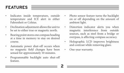
• Indicates inside temperature, outside temperature and ICE alert in either Fahrenheit or Celsius.
• Declination adjustment allows the unit to be set to either true or magnetic north.
• Bearing point stores one compass heading at a time in memory to stay on desired course.
• Automatic power shut-off occurs when no magnetic field changes have been sensed for approximately 10 minutes.
• Programmable backlight auto shut-off feature.
• Photo sensor feature turns the backlight on or off depending on the amount of ambient light.
• Distortion indicator alerts you when magnetic interference from outside sources, such as steel from a bridge or overpass, is affecting compass accuracy.
• Holographic LCD improves brightness and contrast while removing glare.
• One-year warranty.
FEATURES

3
1. The LCD icons are written in all capital letters with quotes around them.
2. Buttons used in procedures are presented as button icons.
3. Procedures are organized so that the action to perform follows the step number, and result of that action is indented.
4. “Press” means press and release a button in less than 2 seconds.
5. “Hold” means press and hold the button for at least 2 seconds, or until a display appears.
6. Indicates a warning or important information
7. Indicates optional equipment avail-able at additional cost.
8. The 3 horizontal lines of display on the right side will be referred to as line 1 through 3 starting at the top.
CONVENTIONS USED IN THIS MANUAL

4
Display and Buttons . . . . . . . . . . . . . . . . . . 5
Installation . . . . . . . . . . . . . . . . . . . . . . . . . 8Step 1: Installing the battery . . . . . . . . . . . 8Step 2: Installing the 12-volt adapter . . . . 9Step 3: Installing the external temperature sensor . . . . . . . . . . . 10Step 4: Mounting the unit . . . . . . . . . . . 12
Programming and Operation . . . . . . . . . 16Calibration mode . . . . . . . . . . . . . . . . . . 16Declination mode . . . . . . . . . . . . . . . . . . 18Backlight mode . . . . . . . . . . . . . . . . . . . . 20Photo sensor feature . . . . . . . . . . . . . . . . 22Bearing mode . . . . . . . . . . . . . . . . . . . . . 23
Barometer mode . . . . . . . . . . . . . . . . . . . 25Weather forecast display . . . . . . . . . . . . . 26Temperature mode . . . . . . . . . . . . . . . . . 27ICE alert feature . . . . . . . . . . . . . . . . . . . 27Altitude mode . . . . . . . . . . . . . . . . . . . . . 28Alt.Set mode . . . . . . . . . . . . . . . . . . . . . . 29
Optional Accessories . . . . . . . . . . . . . . . . 30
Declination Angle Map . . . . . . . . . . . . . . 31
General Specifications . . . . . . . . . . . . . . . 32
Frequently Asked Questions . . . . . . . . . . 35
Service and Replacement . . . . . . . . . . . . . 37
Warranty . . . . . . . . . . . . . . . . . . . . . . . . . . 38
CONTENTS

5
DISPLAY AND BUTTONS
Temperature and Numeric Heading Bearing Point Readout Readout
Declination Icon
Compass Rose Altitude, Barometer Buttons and Weather Forecast Readout
FRONT
Battery Photo Sensor Compartment
Temperature 12-Volt Power Sensor Jack AdapterJack
BACK
6
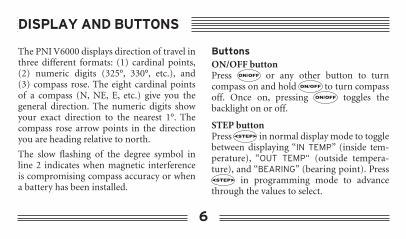
The PNI V6000 displays direction of travel in three different formats: (1) cardinal points, (2) numeric digits (325°, 330°, etc.), and (3) compass rose. The eight cardinal points of a compass (N, NE, E, etc.) give you the general direction. The numeric digits show your exact direction to the nearest 1°. The compass rose arrow points in the direction you are heading relative to north.
The slow flashing of the degree symbol in line 2 indicates when magnetic interference is compromising compass accuracy or when a battery has been installed.
ButtonsON/OFF buttonPress or any other button to turn compass on and hold to turn compass off. Once on, pressing toggles the backlight on or off.
STEP buttonPress in normal display mode to toggle between displaying “IN TEMP” (inside tem-perature), “OUT TEMP“ (outside tempera-ture), and “BEARING” (bearing point). Press
in programming mode to advance through the values to select.
DISPLAY AND BUTTONS

7
MENU buttonPress to advance through programming menu options “CALIb” (calibration), “dECL” (declination), “LIGHt” (backlight), “bEAr” (bearing point), “bAro” (barometer), “tEMP” (temperature) and “ALt” (altimeter) and to exit a programming menu.
ENT buttonPress in normal display mode to toggle between barometric pressure, altitude, and weather forecast. Press in programming mode to store a displayed value.
ALT.SET buttonPress as a quick reset for altitude. It resets the altitude from the currently displayed altitude to the stored altitude.
DISPLAY AND BUTTONS

8
Step 1: Installing the batteryThe PNI V6000 uses a CR123 Lithium type battery, installed according to the diagram on the inside of the battery compartment. Push the battery straight down into the compartment, not at an angle. To remove, open the battery compartment and tap the back of the unit against the palm of your hand and the battery will come out.
Once the battery is inserted, the unit will go through a quality test. If the display becomes stuck, remove the battery, wait for approximately one minute, and then reinsert the battery.
If the battery is the only power source, whenever the battery is changed or removed, the PNI V6000 must be calibrated and all previous feature settings must be reset. With the 12-volt adapter or the hardwire kit installed, the battery may be removed or changed without affecting any settings.
The PNI V6000 has an auto shut-off feature. When no magnetic field change has been detected for approximately 10 minutes, the compass automatically switches off and saves all settings.
INSTALLATION

HEADER
9
Step 2: Installing the 12-volt adapterInstalling the 12-volt adapter is optional, but recommended. Insert the small end into the jack marked “POWER,” located on the back of the compass, and plug the large end into your cigarette lighter receptacle.
The photo sensor feature of the PNI V6000 is operational only when the 12-volt adapter is plugged in or the optional hardwire kit is installed.
Since cars do not always have constant power supplied to the lighter receptacle, you must keep a battery in the PNI V6000 at all times to allow the unit to keep memory settings.
A 15-foot hardwire kit is available at additional cost. See Optional Accessories.
INSTALLATION

HEADER
10
Step 3: Installing the external temperature sensorThe PNI V6000 has a built-in internal temperature sensor designed to measure the temperature inside the vehicle at the windshield (“IN TEMP”).
The PNI V6000 also includes a wire temperature tether designed to measure the temperature outside the vehicle (“OUT TEMP”). The sensor end of the tether must be mounted outside of the passenger compartment, away from engine heat or direct sunlight, in a place where there is
natural airflow to the sensor, such as in the grill area or door jamb. It is best to adhere the sensor on a surface that is least conductive to heat -- such as on a rubber or plastic surface as opposed to the steel body of the vehicle. The temperature from this sensor is displayed as “OUT TEMP.”
Every vehicle is different, making it impossible to list all possible sensor locations. Use your best judgment to select the site for the temperature sensor and experiment with various locations, if necessary.
INSTALLATION

HEADER
11
To install the external temperature sensor:
1. Insert the connector end of the tether into the jack marked “TEMP,” located on the back of the compass.
2. Adhere the sensor end of the tether outside of the passenger compartment. Make sure the mounting surface is free of oil and dirt.
3. (Optional, but suggested) Use the included retainer clips to secure the temperature tether to the windshield or dashboard.
If the temperature sensor is not plugged in and is toggled to “outside temperature” display, the message “PLUG IN TEMP CABLE” will scroll in the upper right corner three times, then will display “_ _ _ °F.”
Do not leave the PNI V6000 in a parked vehicle that is likely to be exposed to extremely hot or cold temperatures.
A 30-foot temperature sensor is available at additional cost. See
INSTALLATION
HEADER
12
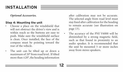
Optional Accessories.
Step 4: Mounting the unit• Choose a place on the windshield that
will not obstruct the driver’s view and is within reach so the buttons are easy to push. Make sure the windshield surface is clean. Once installed, the face of the compass must be pointing toward the rear of the vehicle.
• The unit can be tilted up or down a maximum of 20° from road level. If tilted more than ±20°, the heading information
after calibration may not be accurate. The selected angle from road level must stay fixed after calibration for the heading to remain accurate (see illustration on page 13).
• The accuracy of the PNI V6000 will be diminished by a strong magnetic field, such as that found in proximity to an audio speaker. It is recommended that the unit be mounted 5 or more inches away from stereo speakers.
INSTALLATION

HEADER
13
20° maximum up tilt
20° maximum down tilt
Dashboard
Windshield
Windshield Mounting:
1. Install the suction cups into the mounting bracket by sliding them into their holes (if not pre-installed).
2. Do not loosen the screw at the pivot point where the two-piece bracket is assembled (see illustration on page 14).
3. Insert the small plug end of the 12-volt adapter into the jack marked “POWER”, located on the back of the compass and plug the large plug end into your cigarette lighter receptacle.
4. With the battery and/or 12-volt adapter installed, slide the unit all the way into the shaped compass holder until you hear/feel the “click” when the locking fingers slip into place.
INSTALLATION

HEADER
14
Shaped Compass Holder
Base Plate with suction cups
Pivot point
INSTALLATION

15
5. Hold the base plate where the suction cups are attached in one hand and the shaped compass holder in the other. Rotating the pivot point as little as possible, adjust the bracket for the correct angle.
6. Press the suction cup base firmly against the windshield. If necessary, apply a thin layer of petroleum jelly to improve suction cup grip.
Repeated turning of the bracket at the pivot point will break the teeth in the pivot housing, causing the bracket to not be able to maintain the mounting angle.
Do not leave the PNI V6000 in a parked vehicle that is likely to be exposed to extremely hot or cold temperatures.
INSTALLATION

16
Calibration ModeCalibration is the process whereby the PNI V6000 separates the earth’s magnetic field from other magnetic fields. Without calibra-tion, the unit thinks the entire magnetic field it is reading is from the earth and therefore displays inaccurate compass readings.
Calibration Guidelines1. The PNI V6000 needs to be calibrated (1)
when used for the first time in a vehicle, (2) when moved to a different location in the same vehicle, (3) when moved to a different vehicle, or (4) when the battery is removed if neither the 12-volt adapter
nor the hardwire kit is installed.
2. The PNI V6000 requires recalibration when there has been a change to your vehicle, such as the installation of a new stereo or when the degree symbol on line 2 flashes continuously.
3. If you intend to operate your PNI V6000 with the temperature tether installed, then it should be calibrated after tether installation has been completed.
4. If you drive with your headlights and stereo on, turn these on prior to calibration.
PROGRAMMING AND OPERATION

17
Calibrating the unitTo begin calibration, press to toggle through the programming options until “CALIb” and “SEt” display on screen.
1. Press .“PrESS StEP to StArt” displays.
If is pressed now, the unit returns to normal display.
2. Press .“turn ONCE PrESS Ent to End” displays.
Turn vehicle in one complete circle in either direction. Circle size does not matter. Take
at least 20 seconds to complete the circle.
3. Press .“dONE” flashes once, and the unit returns to normal display mode. If the degree symbol on line 2 flashes after calibration, repeat the calibration process. A flashing degree symbol indicates magnetic distortion. See the Frequently Asked Question section for more information.
PROGRAMMING AND OPERATION

18
Declination ModeDeclination, also called magnetic variation, is the difference between true and magnetic north, relative to a point on the earth. It is measured in degrees to the east or west of true north. The PNI V6000 corrects for dec-lination electronically. Correcting for dec-lination is accomplished by storing in the correct declination angle, and then changing the heading reference from magnetic north to true north (see following section). Decli-nation angles vary throughout the world, and change very slowly over time. See page 31
for a declination angle map for the United States. For the greatest possible accuracy, go to the National Geophysical Data Center web page below to get the declination angle based on your latitude and longitude:http://www.ngdc.noaa.gov/seg/potfld/ushd.shtml. If you do not know your exact latitude and longitude, go to the web page below to get latitude and longitude from your city and state or from your zip code:
http://www.census.gov/cgi-bin/gazetteer
PROGRAMMING AND OPERATION

19
To enter a declination angle
Press to toggle through the program-ming options until “dECL” and “SEt” display on screen.
1. Press . “_ _ °” displays on line 2 and “W” or “E” displays on the compass rose.
2. Press .To toggle between flashing “W” or “E” on compass rose.
3. Press .To select “W” or “E.”
The 10s position on line 2 starts flashing.
4. Press . Display changes from “_ _ °” to “00°” and the 10s position zero is flashing.
Continue to press until the correct number displays.
5. Press .To select the 10s digit, which stops flashing.
The 1s digit begins flashing.
6. Press .To advance the 1s digit.
PROGRAMMING AND OPERATION

20
Continue to press until the correct number displays.
7. Press .To select the 1s digit, which stops flashing.
Press to exit to normal display mode.
To select between true or magnetic north:
Note: The proper declination angle must first be stored as indicated in the previous sec-tion.
1. Press to toggle through the pro-gramming options until “dECL” and “SEt” display on screen.
2. Press to select between true or magnetic north. The declination icon in the upper left corner appears to indicate true north or disappears to indicate magnetic north.
PROGRAMMING AND OPERATION

21
Backlight ModeThe PNI V6000 has a programmable back-light auto shut-off feature when operating on battery power. The default auto shut-off value is 10 seconds, which means that after the backlight has been on for 10 seconds, it will automatically turn off. Other auto shut-off values include 30, 60, 180, and 00 seconds. The auto shut-off feature can be disabled, by selecting “00”, which means that the back-light will stay on until it is manually turned off, or when the unit shuts off after 10 min-utes of no magnetic change. Since the back-
light uses significantly more power than the unit itself, it is recommended that the back-light be turned off when not needed. Alterna-tively, use the 12-volt adapter to save battery life. The backlight can be turned off at any-time by pressing .
To change the backlight auto shut-off value
Press to toggle through the program-ming options until “LIGHt” and “SEt” display on screen.
1. Press .The first numeric time value displays in line
PROGRAMMING AND OPERATION

22
2 and “SEC” in line 3.
2. Press To advance through the values of 10, 30, 60, 180 and 00 seconds respectively.
3. Press .
To select value and exit to normal display mode.
If the 12-volt adapter or optional hardwire kit is installed, the photo sensor feature disables the time value for backlight shut-off.
Photo sensor featureThe PNI V6000 comes equipped with a photo sensor that turns the backlight on or off depending on the amount of ambient light it senses when the 12-volt adapter is plugged in or the optional hardwire kit is installed. The backlight turns on when the unit senses darkness and turns off under the following conditions:
• when the unit senses light again
• when is pressed
• when no magnetic field change has been detected for approximately 10 minutes
PROGRAMMING AND OPERATION

23
Bearing Mode
Quick method of entering a bearing pointPress until “b_ _ _ °” or the last entered bearing value appears in line 1.
1. Align your vehicle so the numeric heading to be stored as a bearing point appears in line 2.
2. Hold to store bearing.
The bearing value will display on line 1. A flashing arrow corresponding to the stored bearing value will appear on the compass rose display whenever the direction of travel differs from the stored bearing.
To erase bearing point, see long method.
Long method of entering a bearing pointPress to toggle through the program-ming options until “bEAr” and “SEt” display on screen.
1. Press . Either “_ _ _ °” or the last entered bearing value appears in line 1 with the 100s digit flashing.
If is held now, the last entered bearing point is erased.
2. Press to enter a bearing point.100s digit advances. Continue pressing until correct digit displays.
PROGRAMMING AND OPERATION

24
3. Press . To store selected digit in 100s position and 10s digit flashes. Press until correct digit displays then press to store. The 1s digit now flashes. Press
to advance digit until correct one displays. Press to store then press
to exit.
The bearing value will display on line 1. In bearing display mode, a flashing arrow representing the stored bearing value will appear on the compass rose if the direction of travel differs from the stored bearing.
To view a stored bearingPress in normal display mode to toggle between the various display options until the bearing point value appears.
PROGRAMMING AND OPERATION

25
Barometer mode The PNI V6000 contains a pressure sensor capable of detecting pressure changes caused by weather conditions, altitude changes, and cabin pressure. The barometer reading reports the same type of value that is reported by most weather reports, namely sea-level pressure.
Press in normal display mode to toggle between the various display options until the “BAROMETER” indicator is on. Barometric pressure is updated every second and appears numerically on the display with an up/down trend arrow. The trend arrow indicates
whether the pressure has increased or decreased over the last hour. The unit stores pressure data continuously, even when off.
To select between “mb” (millibars) or “inHg” (inches of mercury)
Press to toggle through the program-ming options until “bAro” and “SEt” display on screen.
1. Press to toggle between the “mb” or “inHg” indicatorsWhen the scale you want is flashing, press
to select and exit to normal display mode.
PROGRAMMING AND OPERATION
26
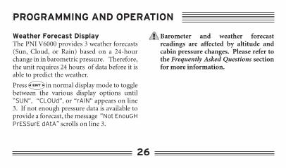
Weather Forecast Display The PNI V6000 provides 3 weather forecasts (Sun, Cloud, or Rain) based on a 24-hour change in in barometric pressure. Therefore, the unit requires 24 hours of data before it is able to predict the weather.
Press in normal display mode to toggle between the various display options until “SUN”, “CLOUd”, or “rAIN” appears on line 3. If not enough pressure data is available to provide a forecast, the message “Not EnouGH PrESSurE dAtA” scrolls on line 3.
Barometer and weather forecast readings are affected by altitude and cabin pressure changes. Please refer to the Frequently Asked Questions section for more information.
PROGRAMMING AND OPERATION

27
Temperature mode
If the temperature sensor has not been properly installed prior to being toggled to “OUT TEMP,” the message “PLUG IN tEMP CAbLE” will scroll three times in the upper right corner, then will display “_ _ _ °F.”
Press to toggle through the program-ming options until “tEMP” and “SEt” display on screen.
1. Press .
To toggle between “°C” or “°F.” When the scale you want is flashing, press to
select and exit to normal display mode.
Do not leave the PNI V6000 in a parked vehicle that is likely to be exposed to extremely hot or cold temperatures.
ICE alert featureWhen the outside temperature sensor has been properly installed, the ICE alert feature can sense and warn you if the temperature drops to 35°F (1°C). When this happens, the PNI V6000 will automatically switch to “TEMP” mode and “ICE” will flash for 20 seconds on line 2 and the temperature will display on line 1.
PROGRAMMING AND OPERATION

28
Altitude mode Press in normal display mode to toggle between the various display options until the “ALTITUDE” indicator is on. The altitude appears numerically with an up/down trend arrow, which indicates whether the altitude is increasing or decreasing as you travel.
You must calibrate the altimeter from a location with a known altitude, such as your house, when the unit is used for the first time in a vehicle. For optimum performance, it is best to recalibrate as often as possible (see Alt.set mode next page).
Press to toggle through the program-ming options until “ALt” and “SEt” display on screen.
1. Press to toggle between “ft” (feet) or “m” (meters).
2. Press to store “ft” or “m.”Either “_ _ _ _ _” or the previous altitude displays in 5 digits on line 3 next to unit of measure selection and the farthest left digit starts flashing.
PROGRAMMING AND OPERATION

HEADER
29
3. Press to advance the first flashing digit.
4. Press to select value.The second digit from the left starts flashing.
When all 5 digits have been assigned values, press to exit to normal display mode.
Alt.set mode
Please refer to the Frequently Asked Questions section for altimeter reading.
To reset altitude back to the value set in altitude mode, press to toggle line 3 display to altitude, then do the following:
1. Hold .The set altitude value now displays on line 3.
PROGRAMMING AND OPERATION
HEADER
30
A 15-foot hard-wire kit is available for an additional charge by calling our cus-tomer service department at (888) 422-6672 from anywhere in the U.S.A., (707) 566-2260, or by e-mail at [email protected]. Please seek the assistance of an automotive accessory installer to ensure proper installation in your specific vehicle.
A 30-foot temperature sensor tether is available for an additional charge by calling our customer service department at (888) 422-6672 from anywhere in the U.S.A., (707) 566-2260, or by e-mail at [email protected].
OPTIONAL ACCESSORIES

HEADER
31
DECLINATION ANGLE MAP
Figure A
Declination angles for the United
States

HEADER
32
• Battery life: 3,600 hours without backlight, 140 hours with constant backlight usage.
• Operating temperature range (°F/°C): 14°F to 140°F / -10°C to 60°C
• Storage temperature range (°F/°C): -40°F to 185°F / -40°C to 85°C
• Temperature resolution/accuracy: 1°F / ±3°F within operating range
• Altimeter function (ft/m): -1,500 ft to 19,995 ft / -455 m to 6045 m
• Altimeter resolution/accuracy: 5 ft / ± 75 ft at constant air pressure
• Barometer function (mb/inHg): 300 to 1,100mb / 8.90 to 32.40 inHg
• Barometer resolution/accuracy: 1mb or 0.03inHg / ±1.5 mb or ±0.044 inHg
GENERAL SPECIFICATIONS

HEADER
33
FREQUENTLY ASKED QUESTIONS
How does the PNI V6000 work?The PNI V6000 uses a patented magnetic sensor technology that was developed by PNI Corporation for the U.S. military. This tech-nology is called magneto-inductive and is the largest advance in compass technology since the fluxgate was invented 60 years ago. The earth generates a magnetic field, and through a mathematical calculation, compass heading is determined. The magneto-inductive technol-ogy is able to electronically sense the difference in the earth’s field from your vehicle’s mag-netic field. The PNI V6000’s microprocessor electronically subtracts out your vehicle’s mag-
netic fields, displaying highly accurate compass readings. Magneto-inductive sensor technol-ogy has many advantages over other technolo-gies, including better performance, less power consumption, and lower cost. These advan-tages have made magneto-inductive sensor technology the choice for many high profile compass applications including GM, Ford, and Chrysler automobiles, Polaris jet skis, Bayliner boats, and Timex watches.
Where can the PNI V6000 be used?The PNI V6000 can be used in any type of vehicle, including cars, trucks, vans, SUVs, off-road vehicles, boats, and RVs.

HEADER
34
What does it mean when the degree symbol on line 2 is flashing slowly?This indicates magnetic distortion. Many things generate external magnetic fields causing compass inaccuracy, including metal and electronics. The PNI V6000 senses any significant change in magnetic fields and the associated magnetic distortion that occurs. The degree symbol may flash briefly when driving over a bridge, under an overpass, over railroad tracks, within close proximity to a strong magnetic field, or when the battery is installed. Once the vehicle has moved away from the source of the magnetic field
or has been calibrated, the PNI V6000 will be accurate. If the degree symbol flashes continuously or immediately after calibration, the unit needs to be calibrated again, where there is less magnetic interference.
How can I maximize weather forecast and altitude accuracy? The PNI V6000 sensor cannot determine the specific cause of a pressure change, such as if the change is due to weather conditions, altitude changes, or cabin pressure. Therefore, for barometer and weather forecast readings to be most accurate, the effect of altitude and cabin pressure must be minimized. Similarly,
FREQUENTLY ASKED QUESTIONS

HEADER
35
the effect of weather condition and cabin pressure changes must be minimized in order for altitude readings to be most accurate.
Will my weather forecast and barometric pressure readings be accurate if my altitude is changing? The PNI V6000 predicts the weather based on changes in pressure. In addition to changes in weather and cabin pressure, pressure also varies depending on altitude.A change of ±50ft in altitude can make the weather forecast inaccurate. Therefore, to obtain an accurate weather forecast when you are changing altitude, make sure you
recalibrate the pressure sensor for that altitude. When recalibrating for a new altitude, weather forecasts may not be accurate for 24 hours. As a guideline, we recommend using the altitude function while traveling and the barometer and weather forecast function while the vehicle is stationary or is within ±30 feet of the last calibrated altitude setting for the last 24 hours.
Why would my altimeter reading change from one day to another when my vehicle is parked at the same location?Even slight weather changes can cause altitude
FREQUENTLY ASKED QUESTIONS

HEADER
36
changes of up to 50 feet, and extreme weather can cause changes of up to 200 feet. Use the Alt.set feature as often as possible and no less than once a day to recalibrate altitude and reset barometric readings to sea-level pressure adjusted for your altitude.
What is vehicle cabin pressure? Changes in vehicle cabin pressure, caused by opening or closing doors or windows or turning ventilation fans on or off, alters the barometric pressure. A change of up to ±50 feet in altitude can occur from cabin pressure changes. To get a more accurate reading, it is recommended that you close your windows
when traveling at highway speeds and set your ventilation system to recirculate inside air instead of bringing in outside air if the fan is on. Pressing every morning will reset the altimeter to its original setting.
How can the bearing point feature help me?Following the position of the sun and spot-ting familiar landmarks can give you an idea of what direction you are heading in during the day. This differs at night or on a foggy day when the sun and landmarks are obscured. By setting a bearing point and monitoring your headings, you can be far more certain of direction, even on unfamiliar roads.
FREQUENTLY ASKED QUESTIONS

HEADER
37
SERVICE AND REPLACEMENT
Customer Service Please e-mail customer service department at [email protected] or call us between the hours of 8:00 a.m. and 5:00 p.m. (PST) Monday through Friday, with questions not answered here.
Replacement Service For the fastest service, it is best to contact or return your unit to the place of purchase within 30 days of the purchase. If you wish to return the unit for replacement or repair to PNI Corporation, please do the following:
1. Obtain a return merchandise authoriza-tion (RMA) number by contacting PNI:
• By phone: (888) 422-6672 (toll-free within the U.S.A. only) or at (707) 566-2260 between 8:00 a.m. and 5:00 p.m. (PST).
• By fax: (707) 566-2261
• By e-mail: [email protected]
2. Provide a proof of purchase, such as a mechanical reproduction or carbon copy of your sales receipt. If you send your original receipt, it cannot be returned. Proof-of-purchase must show printed date of purchase, model number, and place of purchase. There will be a charge for repair/replacement if no proof of

38
purchase is provided, or if it is past the 12-month warranty period.
Once you have acquired a RMA number, pack the unit securely to prevent damage in transit. If possible, use the original packing material and box. Be sure to send the entire product.
3. Ship prepaid and insured by way of a traceable carrier such as United Parcel Service (UPS), Roadway Parcel Service (RPS), or First Class Mail to avoid loss in transit.
4. Write the issued RMA number on the
outside of your package and send your proof-of-purchase and description of the problem to the following address:
PNI Corporation5464 Skylane Boulevard, Suite ASanta Rosa, CA 95403-1084
Type or print your name and address where the replacement should be delivered. After receipt of your documents and unit, a replacement unit will be sent to you. Please allow 2 to 3 weeks from receipt of your returned product to delivery of your replacement.
SERVICE AND REPLACEMENT

HEADER
39
LIMITED WARRANTY; LIMITATION OF LIABILITY
PNI Corporation warrants to the original user that this product will be free of defects in workmanship and materials for one (1) year from the date of purchase. This warranty does not cover wear and tear due to normal use, or damage to the product as the result of improper usage, neglect of care, alteration, accident or unauthorized repair.
If the product is found by PNI to be defective and you have provided proof of purchase acceptable to PNI, PNI’s entire liability and your exclusive remedy for breach of warranty shall be that PNI, at its
option, will replace or repair the product and return the replacement or repaired product to you at no charge, provided that you ship the product to PNI at your expense. PNI warrants the repaired or replaced product to be free from defects in material and workmanship for a period of: (i) ninety (90) days from the date it is shipped to you; or (ii) the period of time remaining on the original one (1) year warranty.
THE FOREGOING WARRANTY IS GIVEN IN LIEU OF AND PNI DISCLAIMS ALL OTHER WARRANTIES OR REPRESEN-

HEADER
40
LIMITED WARRANTY; LIMITATION OF LIABILITY
TATIONS, EXPRESSED OR IMPLIED, IN FACT OR IN LAW, WITH RESPECT TO THIS PRODUCT, INCLUDING, BUT NOT LIMITED TO, (1) THE IMPLIED WAR-RANTIES OF MERCHANTABILITY AND OF FITNESS FOR A PARTICULAR PUR-POSE, OR (2) THAT USE OF THE PROD-UCT WILL BE UNINTERRUPTED AND ERROR FREE.
PNI shall have no liability for any indirect or speculative damages (including, but not limited to, consequential, incidental and special damages) relating to the use of or inability to use this product, whether arising
out of contract, negligence, tort, or under any warranty theory, or for infringement of any other party’s intellectual property rights, irrespective of whether PNI had advance notice of the possibility of any such damages, including, but not limited to, loss of use, revenue or profit. In no event shall PNI’s total liability for all claims regarding the product exceed the price paid for the product. PNI neither assumes nor authorizes anyone to assume for it any other liabilities.


PNI Corporation www.pnicorp.com
80-1286-0001 Version G1-01


