47
Operating Manual — No. 1002104-EN-01 PNOZmulti Modular Safety System PNOZmulti Modbus/TCP _Name_Bookmark2_ _Name_Bookmark2_
Operating Manual — No. 1002104-EN-01
PNOZmulti Modular Safety System
PNOZmulti Modbus/TCP
_Name_Bookmark2_
_Name_Bookmark2_

��������� ���������� ������ ������������� ������� ��
����������������������� ����� ��������������������������������������� ���������������
����� ��� ��� � �����
!������� ��� ������ ��������� ���� ����������� ����� �"�������������������������
����#$��%�#$��&%#$��'()#$������#$��!*'#$��!!#$��+%!#$�!�����,-!� #$�!�����*.*#$
!�����'*�� #$������ ��������������#����������������� �� ����������������/����
�������������������� ������� ������
!0���� ��!����0�������
_Name_Bookmark2_
Pilz GmbH & Co. KG, Felix-Wankel-Straße 2, 73760 Ostfildern, Germany
Telephone: +49 711 3409-0, Telefax: +49 711 3409-133, E-Mail: [email protected]
Contents
Contents
Contents Page
Chapter 1 Introduction
1.1 Validity of documentation 1-1
1.1.1 Retaining the documentation 1-1
1.2 Overview of documentation 1-2
1.3 Definition of symbols 1-3
1.4 System requirements 1-4
Chapter 2 Communication via Modbus/TCP
2.1 Modbus/TCP - Basics 2-1
2.2 Modbus/TCP with PNOZmulti 2-2
Chapter 3 Modbus/TCP - Data areas
3.1 Overview 3-1
3.2 Function codes 3-2
3.3 Data transfer limits 3-3
3.4 Assignment of data areas 3-4
3.4.1 Virtual inputs 3-4
3.4.2 Control Register 3-5
3.4.3 Virtual outputs 3-6
3.4.4 LEDs 3-7
3.4.5 Configuration 3-7
3.4.6 State of the inputs from the base unit and
expansion modules
3-10
3.4.7 State of the outputs from the base unit and
expansion modules
3-11
3.4.8 LED status 3-12
3.4.9 Diagnostic word, element types 3-14
3.4.10 Current state of the virtual inputs 3-22
3.4.11 State of process data 3-23
3.5 Updating the data areas 3-24
3.6 Bit addressing in a Register 3-25
Chapter 4 Application example
4.1 Modbus subscriber 4-1
4.2 Data exchange via Modbus/TCP 4-2
4.3 Device configuration 4-5
4.3.1 Modular safety system PNOZmulti 4-5
4.3.2 PSSu system in the automation system
PSS 4000
4-6
4.3.3 Operator terminal PMI 4-9

Contents
Pilz GmbH & Co. KG, Felix-Wankel-Straße 2, 73760 Ostfildern, Germany
Telephone: +49 711 3409-0, Telefax: +49 711 3409-133, E-Mail: [email protected]
Pilz GmbH & Co. KG, Felix-Wankel-Straße 2, 73760 Ostfildern, Germany
Telephone: +49 711 3409-0, Telefax: +49 711 3409-133, E-Mail: [email protected]
1.1 Validity of documentation
1 Introduction
11000IntroductionIntroduction1-1.1Validity of documentation1100Validity of documentation1-Einf Einleitung
This operating manual explains the function and operation, describes
the installation and provides guidelines on how to connect the product .
1.1.1 Retaining the documentationRetaining the documentation1-Einf Aufbewahren
This documentation is intended for instruction and should be retained
for future reference.
1.2 Overview of documentation
1 Introduction
Pilz GmbH & Co. KG, Felix-Wankel-Straße 2, 73760 Ostfildern, Germany
Telephone: +49 711 3409-0, Telefax: +49 711 3409-133, E-Mail: [email protected]
1.2Overview of documentation1200Overview of documentation1-Einf_Uebersicht_über_die_Doku_6_Inbetriebnahme
1 Introduction
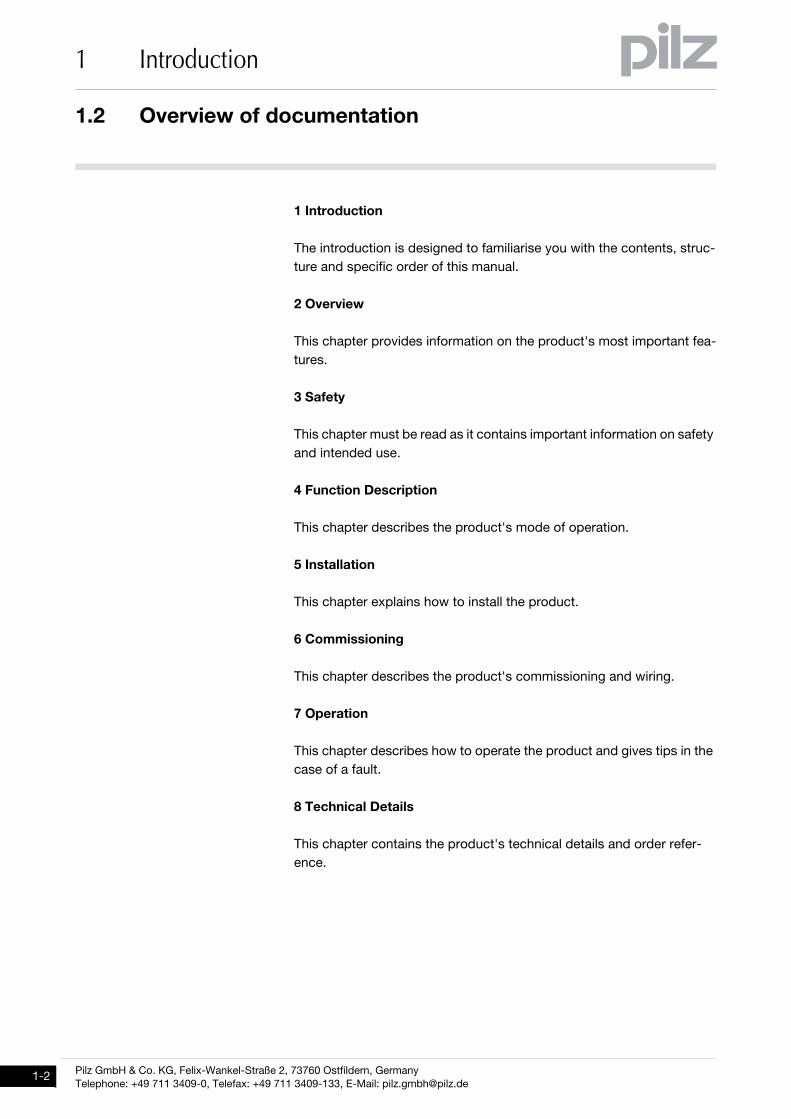
The introduction is designed to familiarise you with the contents, struc-
ture and specific order of this manual.
2 Overview
This chapter provides information on the product's most important fea-
tures.
3 Safety
This chapter must be read as it contains important information on safety
and intended use.
4 Function Description
This chapter describes the product's mode of operation.
5 Installation
This chapter explains how to install the product.
6 Commissioning
This chapter describes the product's commissioning and wiring.
7 Operation
This chapter describes how to operate the product and gives tips in the
case of a fault.
8 Technical Details
This chapter contains the product's technical details and order refer-
ence.
Pilz GmbH & Co. KG, Felix-Wankel-Straße 2, 73760 Ostfildern, Germany
Telephone: +49 711 3409-0, Telefax: +49 711 3409-133, E-Mail: [email protected]
1.3 Definition of symbols
1 Introduction
1.3Definition of symbols1300Definition of symbols1-Einfhrung Zeichen
Information that is particularly important is identified as follows:
DANGER!
This warning must be heeded! It warns of a hazardous situation
that poses an immediate threat of serious injury and death and
indicates preventive measures that can be taken.
WARNING!
This warning must be heeded! It warns of a hazardous situation
that could lead to serious injury and death and indicates preven-
tive measures that can be taken.
CAUTION!
This refers to a hazard that can lead to a less serious or minor
injury plus material damage, and also provides information on
preventive measures that can be taken.
NOTICE
This describes a situation in which the product or devices could
be damaged and also provides information on preventive meas-
ures that can be taken.
INFORMATION
This gives advice on applications and provides information on
special features, as well as highlighting areas within the text that
are of particular importance.
1.4 System requirements
1 Introduction
Pilz GmbH & Co. KG, Felix-Wankel-Straße 2, 73760 Ostfildern, Germany
Telephone: +49 711 3409-0, Telefax: +49 711 3409-133, E-Mail: [email protected]
1.4System requirements1400System requirements1-Systemvoraussetzungen Modbus
PNOZmulti Configurator: From Version 7.1.0
Base unit PNOZ m0p ETH: From Version 1.0
Base unit PNOZ m1p ETH: From Version 2.1
Base unit PNOZ m2p ETH: From Version 1.0
Base unit PNOZ m3p ETH: From Version 1.0
Expansion module PNOZ mmc1p ETH from Version 1.0
Please contact Pilz if you have an older version.
Pilz GmbH & Co. KG, Felix-Wankel-Straße 2, 73760 Ostfildern, Germany
Telephone: +49 711 3409-0, Telefax: +49 711 3409-133, E-Mail: [email protected]
2.1 Modbus/TCP - Basics
2 Communication via Modbus/TCP
22000Communication via Modbus/TCPCommunication via Modbus/TCP2-2.1 Modbus/TCP - Basics2100 Modbus/TCP - Basics2-ModbusTCP_Modbus/TCP Allg-1
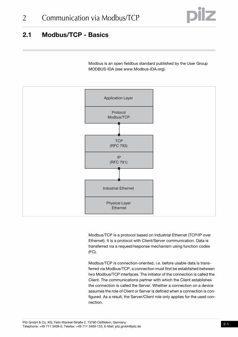
Modbus is an open fieldbus standard published by the User Group
MODBUS-IDA (see www.Modbus-IDA.org).
Modbus/TCP is a protocol based on Industrial Ethernet (TCP/IP over
Ethernet). It is a protocol with Client/Server communication. Data is
transferred via a request/response mechanism using function codes
(FC).
Modbus/TCP is connection-oriented, i.e. before usable data is trans-
ferred via Modbus/TCP, a connection must first be established between
two Modbus/TCP interfaces. The initiator of the connection is called the
Client. The communications partner with which the Client establishes
the connection is called the Server. Whether a connection on a device
assumes the role of Client or Server is defined when a connection is con-
figured. As a result, the Server/Client role only applies for the used con-
nection.
������������ ��
�����
���������
���
���������
�
�������!�
���������"�#����
�# �������� ��
"�#����
2.2 Modbus/TCP with PNOZmulti
2 Communication via Modbus/TCP
Pilz GmbH & Co. KG, Felix-Wankel-Straße 2, 73760 Ostfildern, Germany
Telephone: +49 711 3409-0, Telefax: +49 711 3409-133, E-Mail: [email protected]
2.2Modbus/TCP with PNOZmulti2200Modbus/TCP with PNOZmulti2-ModbusTCP_Modbus/TCP Allg-2-PNOZmulti
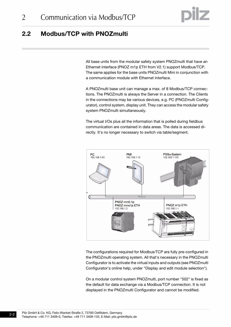
All base units from the modular safety system PNOZmulti that have an
Ethernet interface (PNOZ m1p ETH from V2.1) support Modbus/TCP.
The same applies for the base units PNOZmulti Mini in conjunction with
a communication module with Ethernet interface.
A PNOZmulti base unit can manage a max. of 8 Modbus/TCP connec-
tions. The PNOZmulti is always the Server in a connection. The Clients
in the connections may be various devices, e.g. PC (PNOZmulti Config-
urator), control system, display unit. They can access the modular safety
system PNOZmulti simultaneously.
The virtual I/Os plus all the information that is polled during fieldbus
communication are contained in data areas. The data is accessed di-
rectly. It's no longer necessary to switch via table/segment.
The configurations required for Modbus/TCP are fully pre-configured in
the PNOZmulti operating system. All that's necessary in the PNOZmulti
Configurator is to activate the virtual inputs and outputs (see PNOZmulti
Configurator's online help, under "Display and edit module selection").
On a modular control system PNOZmulti, port number "502" is fixed as
the default for data exchange via a Modbus/TCP connection. It is not
displayed in the PNOZmulti Configurator and cannot be modified.
Pilz GmbH & Co. KG, Felix-Wankel-Straße 2, 73760 Ostfildern, Germany
Telephone: +49 711 3409-0, Telefax: +49 711 3409-133, E-Mail: [email protected]
3.1 Overview
3 Modbus/TCP - Data areas
33000Modbus/TCP - Data areasModbus/TCP - Data areas3-3.1Overview3100Overview3-ModbusTCP_Modbus/TCP-Datenbereiche-PNOZmulti
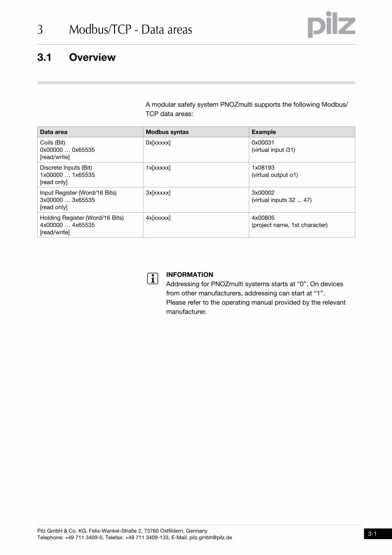
A modular safety system PNOZmulti supports the following Modbus/
TCP data areas:
Data area Modbus syntax Example
Coils (Bit)
0x00000 … 0x65535
[read/write]
0x[xxxxx] 0x00031
(virtual input i31)
Discrete Inputs (Bit)
1x00000 … 1x65535
[read only]
1x[xxxxx] 1x08193
(virtual output o1)
Input Register (Word/16 Bits)
3x00000 … 3x65535
[read only]
3x[xxxxx] 3x00002
(virtual inputs 32 ... 47)
Holding Register (Word/16 Bits)
4x00000 … 4x65535
[read/write]
4x[xxxxx] 4x00805
(project name, 1st character)
INFORMATION
Addressing for PNOZmulti systems starts at “0”. On devices
from other manufacturers, addressing can start at “1”.
Please refer to the operating manual provided by the relevant
manufacturer.
3.2 Function codes
3 Modbus/TCP - Data areas
Pilz GmbH & Co. KG, Felix-Wankel-Straße 2, 73760 Ostfildern, Germany
Telephone: +49 711 3409-0, Telefax: +49 711 3409-133, E-Mail: [email protected]
3.2Function codes3200Function codes3-ModbusTCP_Function Codes-PNOZmulti
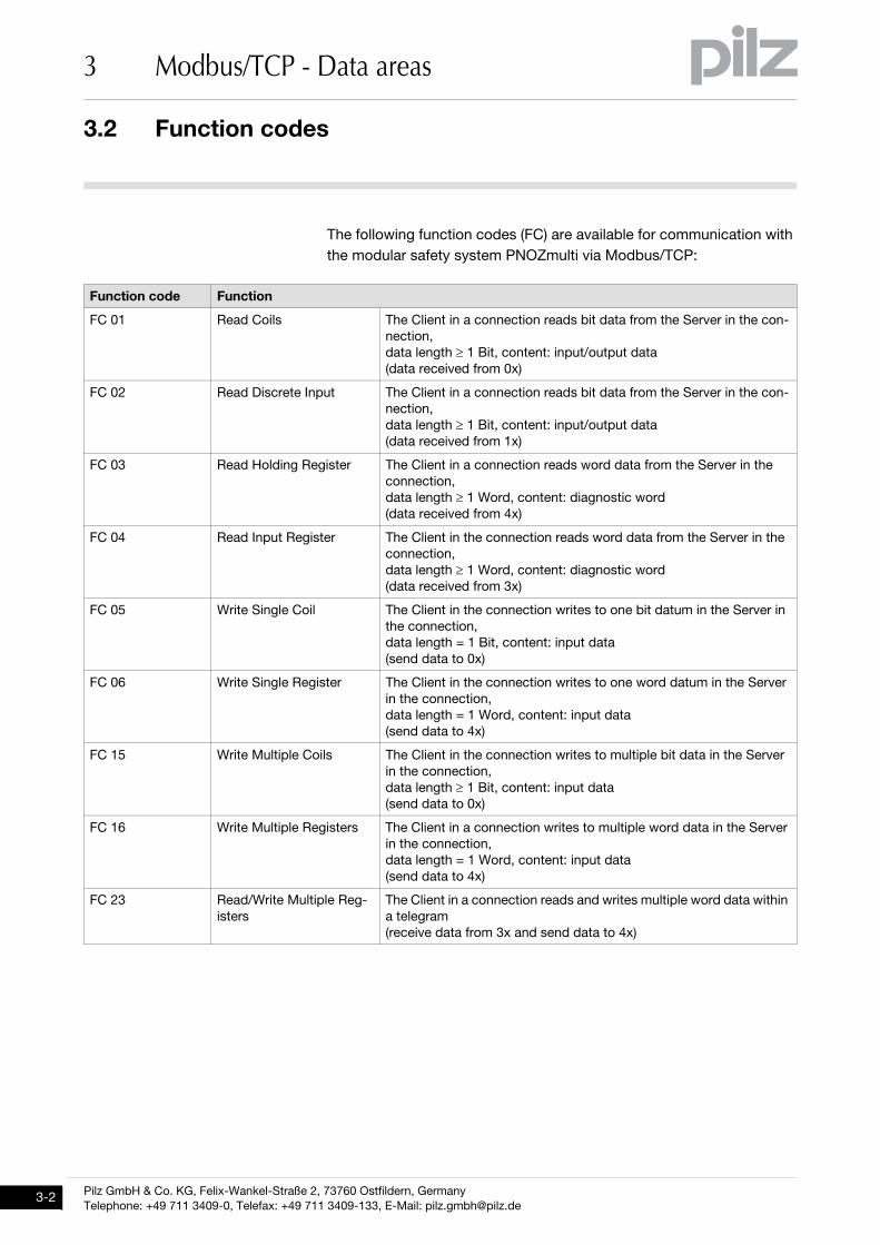
The following function codes (FC) are available for communication with
the modular safety system PNOZmulti via Modbus/TCP:
Function code Function
FC 01 Read Coils The Client in a connection reads bit data from the Server in the con-
nection,
data length ≥ 1 Bit, content: input/output data
(data received from 0x)
FC 02 Read Discrete Input The Client in a connection reads bit data from the Server in the con-
nection,
data length ≥ 1 Bit, content: input/output data
(data received from 1x)
FC 03 Read Holding Register The Client in a connection reads word data from the Server in the
connection,
data length ≥ 1 Word, content: diagnostic word
(data received from 4x)
FC 04 Read Input Register The Client in the connection reads word data from the Server in the
connection,
data length ≥ 1 Word, content: diagnostic word
(data received from 3x)
FC 05 Write Single Coil The Client in the connection writes to one bit datum in the Server in
the connection,
data length = 1 Bit, content: input data
(send data to 0x)
FC 06 Write Single Register The Client in the connection writes to one word datum in the Server
in the connection,
data length = 1 Word, content: input data
(send data to 4x)
FC 15 Write Multiple Coils The Client in the connection writes to multiple bit data in the Server
in the connection,
data length ≥ 1 Bit, content: input data
(send data to 0x)
FC 16 Write Multiple Registers The Client in a connection writes to multiple word data in the Server
in the connection,
data length = 1 Word, content: input data
(send data to 4x)
FC 23 Read/Write Multiple Reg-
isters
The Client in a connection reads and writes multiple word data within
a telegram
(receive data from 3x and send data to 4x)
Pilz GmbH & Co. KG, Felix-Wankel-Straße 2, 73760 Ostfildern, Germany
Telephone: +49 711 3409-0, Telefax: +49 711 3409-133, E-Mail: [email protected]
3.3 Data transfer limits
3 Modbus/TCP - Data areas
3.3Data transfer limits3300Data transfer limits3-ModbusTCP_Grenzen Datenübertragung-PNOZmulti
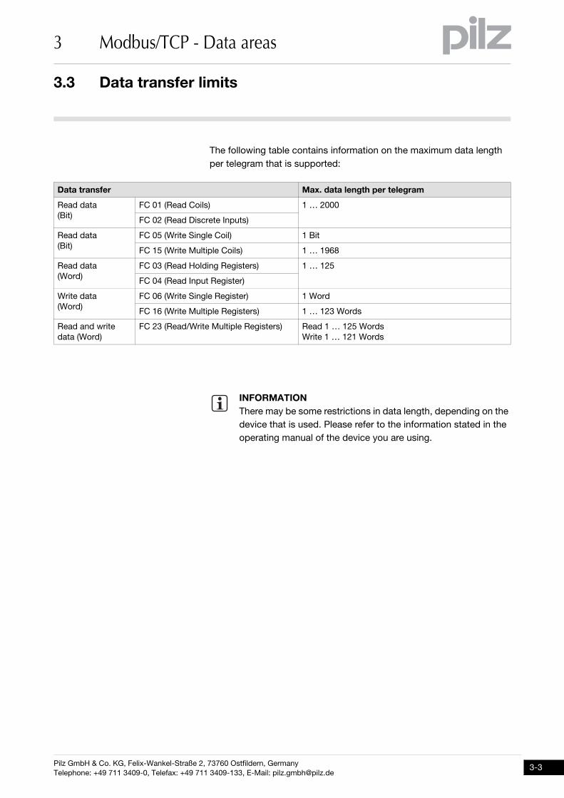
The following table contains information on the maximum data length
per telegram that is supported:
Data transfer Max. data length per telegram
Read data
(Bit)
FC 01 (Read Coils) 1 … 2000
FC 02 (Read Discrete Inputs)
Read data
(Bit)
FC 05 (Write Single Coil) 1 Bit
FC 15 (Write Multiple Coils) 1 … 1968
Read data
(Word)
FC 03 (Read Holding Registers) 1 … 125
FC 04 (Read Input Register)
Write data
(Word)
FC 06 (Write Single Register) 1 Word
FC 16 (Write Multiple Registers) 1 … 123 Words
Read and write
data (Word)
FC 23 (Read/Write Multiple Registers) Read 1 … 125 Words
Write 1 … 121 Words
INFORMATION
There may be some restrictions in data length, depending on the
device that is used. Please refer to the information stated in the
operating manual of the device you are using.
3.4 Assignment of data areas
3 Modbus/TCP - Data areas
Pilz GmbH & Co. KG, Felix-Wankel-Straße 2, 73760 Ostfildern, Germany
Telephone: +49 711 3409-0, Telefax: +49 711 3409-133, E-Mail: [email protected]
3.4Assignment of data areas3400Assignment of data areas3-ModbusTCP_Coil and Register Map-Einleitung-PNOZmulti
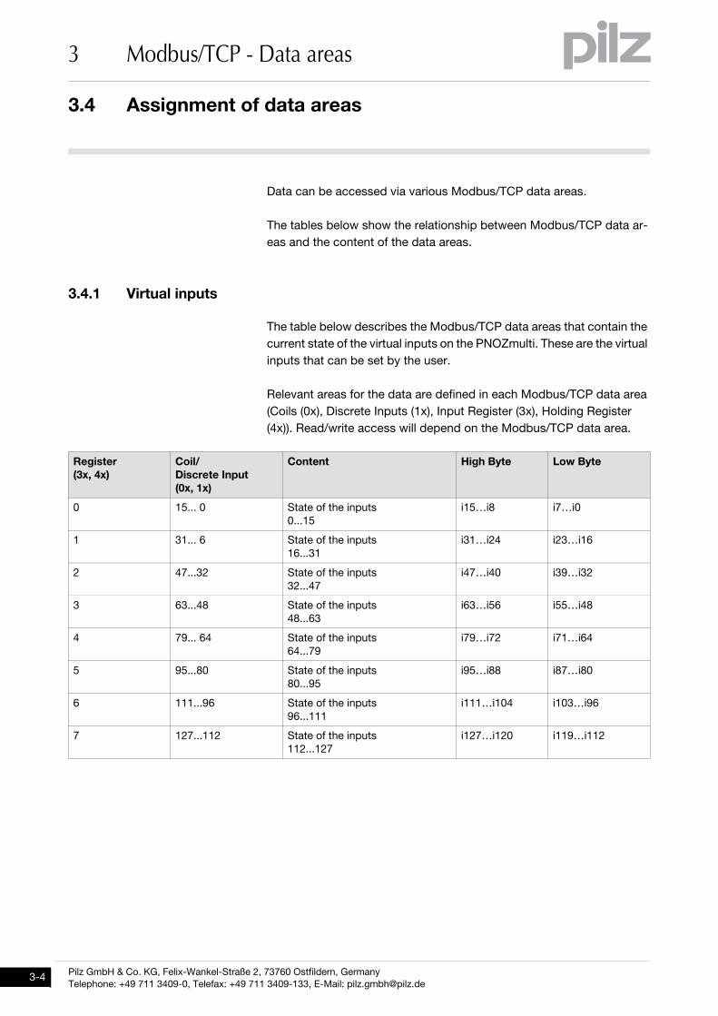
Data can be accessed via various Modbus/TCP data areas.
The tables below show the relationship between Modbus/TCP data ar-
eas and the content of the data areas.
3.4.1 Virtual inputsVirtual inputs3-ModbusTCP_Datenbereiche-Virtuelle Eingänge-PNOZmulti
The table below describes the Modbus/TCP data areas that contain the
current state of the virtual inputs on the PNOZmulti. These are the virtual
inputs that can be set by the user.
Relevant areas for the data are defined in each Modbus/TCP data area
(Coils (0x), Discrete Inputs (1x), Input Register (3x), Holding Register
(4x)). Read/write access will depend on the Modbus/TCP data area.
Register
(3x, 4x)
Coil/
Discrete Input
(0x, 1x)
Content High Byte Low Byte
0 15... 0 State of the inputs
0...15
i15…i8 i7…i0
1 31... 6 State of the inputs
16...31
i31…i24 i23…i16
2 47...32 State of the inputs
32...47
i47…i40 i39…i32
3 63...48 State of the inputs
48...63
i63…i56 i55…i48
4 79... 64 State of the inputs
64...79
i79…i72 i71…i64
5 95...80 State of the inputs
80...95
i95…i88 i87…i80
6 111...96 State of the inputs
96...111
i111…i104 i103…i96
7 127...112 State of the inputs
112...127
i127…i120 i119…i112
Pilz GmbH & Co. KG, Felix-Wankel-Straße 2, 73760 Ostfildern, Germany
Telephone: +49 711 3409-0, Telefax: +49 711 3409-133, E-Mail: [email protected]
3.4 Assignment of data areas
3 Modbus/TCP - Data areas
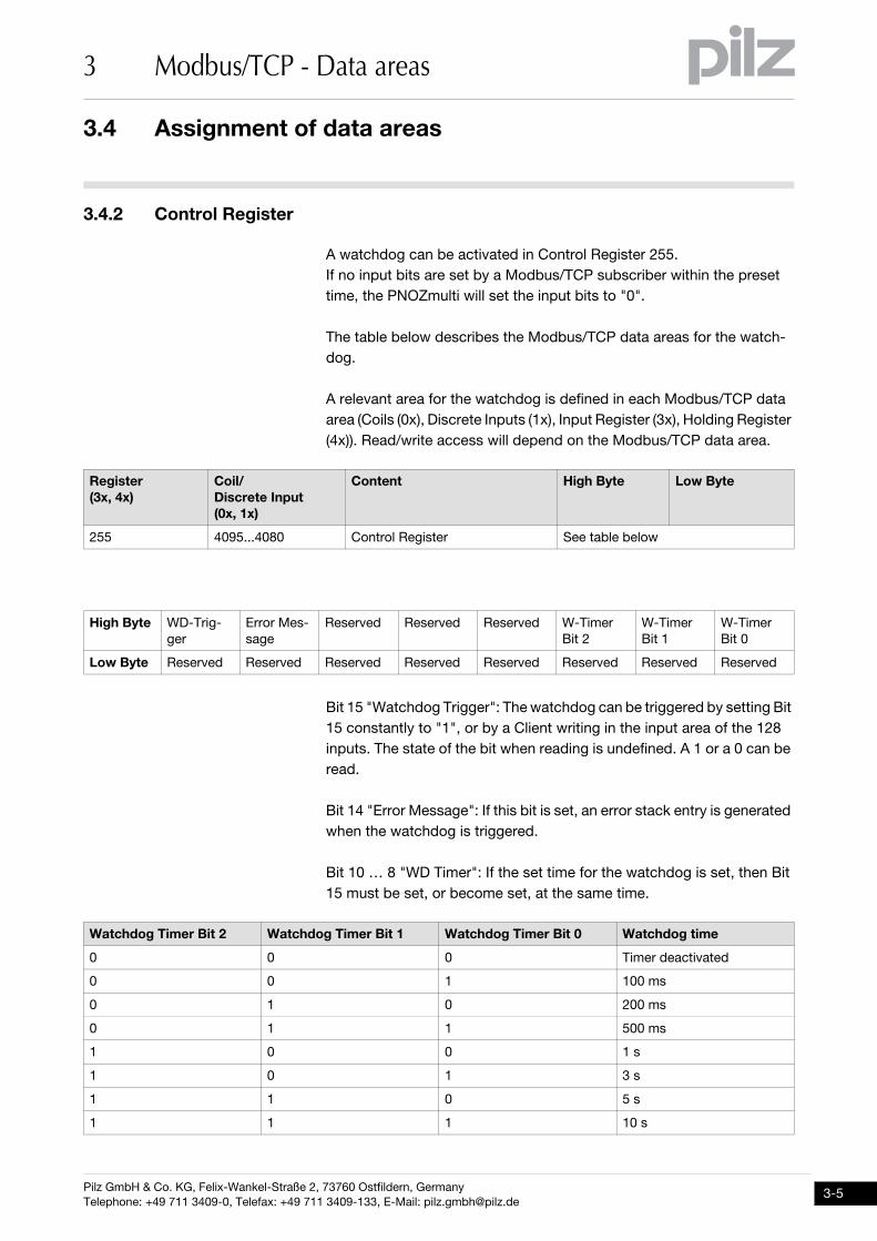
3.4.2 Control RegisterControl Register3-ModbusTCP_Datenbereiche-Control Register-PNOZmulti
A watchdog can be activated in Control Register 255.
If no input bits are set by a Modbus/TCP subscriber within the preset
time, the PNOZmulti will set the input bits to "0".
The table below describes the Modbus/TCP data areas for the watch-
dog.
A relevant area for the watchdog is defined in each Modbus/TCP data
area (Coils (0x), Discrete Inputs (1x), Input Register (3x), Holding Register
(4x)). Read/write access will depend on the Modbus/TCP data area.
Bit 15 "Watchdog Trigger": The watchdog can be triggered by setting Bit
15 constantly to "1", or by a Client writing in the input area of the 128
inputs. The state of the bit when reading is undefined. A 1 or a 0 can be
read.
Bit 14 "Error Message": If this bit is set, an error stack entry is generated
when the watchdog is triggered.
Bit 10 … 8 "WD Timer": If the set time for the watchdog is set, then Bit
15 must be set, or become set, at the same time.
Register
(3x, 4x)
Coil/
Discrete Input
(0x, 1x)
Content High Byte Low Byte
255 4095...4080 Control Register See table below
High Byte WD-Trig-
ger
Error Mes-
sage
Reserved Reserved Reserved W-Timer
Bit 2
W-Timer
Bit 1
W-Timer
Bit 0
Low Byte Reserved Reserved Reserved Reserved Reserved Reserved Reserved Reserved
Watchdog Timer Bit 2 Watchdog Timer Bit 1 Watchdog Timer Bit 0 Watchdog time
0 0 0 Timer deactivated
0 0 1 100 ms
0 1 0 200 ms
0 1 1 500 ms
1 0 0 1 s
1 0 1 3 s
1 1 0 5 s
1 1 1 10 s
3.4 Assignment of data areas
3 Modbus/TCP - Data areas
Pilz GmbH & Co. KG, Felix-Wankel-Straße 2, 73760 Ostfildern, Germany
Telephone: +49 711 3409-0, Telefax: +49 711 3409-133, E-Mail: [email protected]
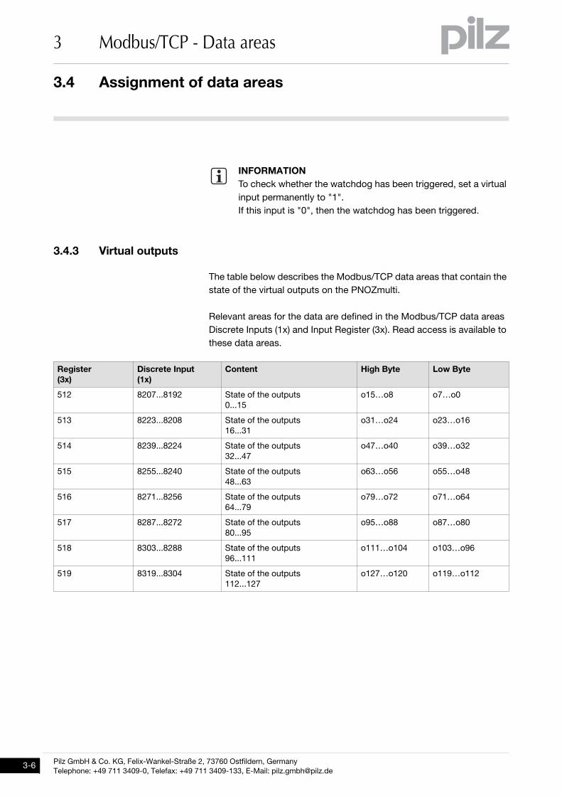
3.4.3 Virtual outputsVirtual outputs3-ModbusTCP_Datenbereiche-Virtuelle Ausgänge-PNOZmulti
The table below describes the Modbus/TCP data areas that contain the
state of the virtual outputs on the PNOZmulti.
Relevant areas for the data are defined in the Modbus/TCP data areas
Discrete Inputs (1x) and Input Register (3x). Read access is available to
these data areas.
INFORMATION
To check whether the watchdog has been triggered, set a virtual
input permanently to "1".
If this input is "0", then the watchdog has been triggered.
Register
(3x)
Discrete Input
(1x)
Content High Byte Low Byte
512 8207...8192 State of the outputs
0...15
o15…o8 o7…o0
513 8223...8208 State of the outputs
16...31
o31…o24 o23…o16
514 8239...8224 State of the outputs
32...47
o47…o40 o39…o32
515 8255...8240 State of the outputs
48...63
o63…o56 o55…o48
516 8271...8256 State of the outputs
64...79
o79…o72 o71…o64
517 8287...8272 State of the outputs
80...95
o95…o88 o87…o80
518 8303...8288 State of the outputs
96...111
o111…o104 o103…o96
519 8319...8304 State of the outputs
112...127
o127…o120 o119…o112
Pilz GmbH & Co. KG, Felix-Wankel-Straße 2, 73760 Ostfildern, Germany
Telephone: +49 711 3409-0, Telefax: +49 711 3409-133, E-Mail: [email protected]
3.4 Assignment of data areas
3 Modbus/TCP - Data areas
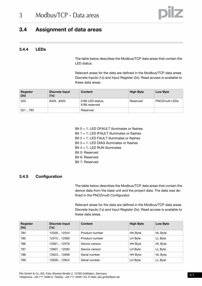
3.4.4 LEDsLEDs3-ModbusTCP_Datenbereiche-LEDs-PNOZmulti
The table below describes the Modbus/TCP data areas that contain the
LED status.
Relevant areas for the data are defined in the Modbus/TCP data areas
Discrete Inputs (1x) and Input Register (3x). Read access is available to
these data areas.
Bit 0 = 1: LED OFAULT illuminates or flashes
Bit 1 = 1: LED IFAULT illuminates or flashes
Bit 2 = 1: LED FAULT illuminates or flashes
Bit 3 = 1: LED DIAG illuminates or flashes
Bit 4 = 1: LED RUN illuminates
Bit 5: Reserved
Bit 6: Reserved
Bit 7: Reserved
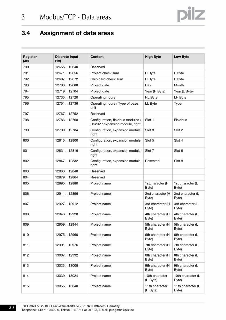
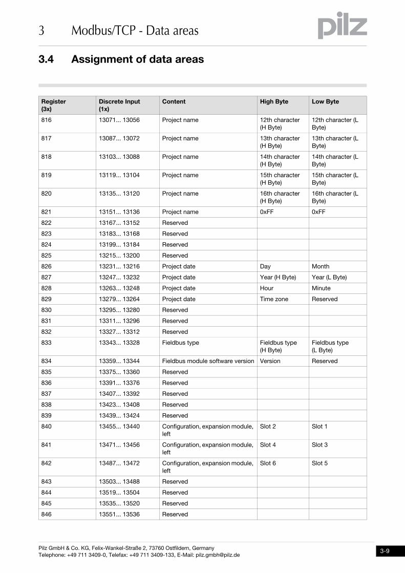
3.4.5 ConfigurationConfiguration3-ModbusTCP_Datenbereiche-Konfiguration-PNOZmulti
The table below describes the Modbus/TCP data areas that contain the
device data from the base unit and the project data. The data was de-
fined in the PNOZmulti Configurator.
Relevant areas for the data are defined in the Modbus/TCP data areas
Discrete Inputs (1x) and Input Register (3x). Read access is available to
these data areas.
Register
(3x)
Discrete Input
(1x)
Content High Byte Low Byte
520 8335...8320 8 Bit LED status;
8 Bit reserved
Reserved PNOZmulti LEDs
521…783 Reserved
Register
(3x)
Discrete Input
(1x)
Content High Byte Low Byte
784 12559... 12544 Product number HH Byte HL Byte
785 12575... 12560 Product number LH Byte LL Byte
786 12591... 12576 Device version HH Byte HL Byte
787 12607... 12592 Device version LH Byte LL Byte
788 12623... 12608 Serial number HH Byte HL Byte
789 12639... 12624 Serial number LH Byte LL Byte
3.4 Assignment of data areas
3 Modbus/TCP - Data areas
Pilz GmbH & Co. KG, Felix-Wankel-Straße 2, 73760 Ostfildern, Germany
Telephone: +49 711 3409-0, Telefax: +49 711 3409-133, E-Mail: [email protected]
790 12655... 12640 Reserved
791 12671... 12656 Project check sum H Byte L Byte
792 12687... 12672 Chip card check sum H Byte L Byte
793 12703... 12688 Project date Day Month
794 12719... 12704 Project date Year (H Byte) Year (L Byte)
795 12735... 12720 Operating hours HL Byte LH Byte
796 12751... 12736 Operating hours / Type of base
unit
LL Byte Type
797 12767... 12752 Reserved
798 12783... 12768 Configuration, fieldbus modules /
RS232 / expansion module, right
Slot 1 Fieldbus
799 12799... 12784 Configuration, expansion module,
right
Slot 3 Slot 2
800 12815... 12800 Configuration, expansion module,
right
Slot 5 Slot 4
801 12831... 12816 Configuration, expansion module,
right
Slot 7 Slot 6
802 12847... 12832 Configuration, expansion module,
right
Reserved Slot 8
803 12863... 12848 Reserved
804 12879... 12864 Reserved
805 12895... 12880 Project name 1stcharacter (H
Byte)
1st character (L
Byte)
806 12911... 12896 Project name 2nd character (H
Byte)
2nd character (L
Byte)
807 12927... 12912 Project name 3rd character (H
Byte)
3rd character (L
Byte)
808 12943... 12928 Project name 4th character (H
Byte)
4th character (L
Byte)
809 12959... 12944 Project name 5th character (H
Byte)
5th character (L
Byte)
810 12975... 12960 Project name 6th character (H
Byte)
6th character (L
Byte)
811 12991... 12976 Project name 7th character (H
Byte)
7th character (L
Byte)
812 13007... 12992 Project name 8th character (H
Byte)
8th character (L
Byte)
813 13023... 13008 Project name 9th character (H
Byte)
9th character (L
Byte)
814 13039... 13024 Project name 10th character
(H Byte)
10th character (L
Byte)
815 13055... 13040 Project name 11th character
(H Byte)
11th character (L
Byte)
Register
(3x)
Discrete Input
(1x)
Content High Byte Low Byte
Pilz GmbH & Co. KG, Felix-Wankel-Straße 2, 73760 Ostfildern, Germany
Telephone: +49 711 3409-0, Telefax: +49 711 3409-133, E-Mail: [email protected]
3.4 Assignment of data areas
3 Modbus/TCP - Data areas
816 13071... 13056 Project name 12th character
(H Byte)
12th character (L
Byte)
817 13087... 13072 Project name 13th character
(H Byte)
13th character (L
Byte)
818 13103... 13088 Project name 14th character
(H Byte)
14th character (L
Byte)
819 13119... 13104 Project name 15th character
(H Byte)
15th character (L
Byte)
820 13135... 13120 Project name 16th character
(H Byte)
16th character (L
Byte)
821 13151... 13136 Project name 0xFF 0xFF
822 13167... 13152 Reserved
823 13183... 13168 Reserved
824 13199... 13184 Reserved
825 13215... 13200 Reserved
826 13231... 13216 Project date Day Month
827 13247... 13232 Project date Year (H Byte) Year (L Byte)
828 13263... 13248 Project date Hour Minute
829 13279... 13264 Project date Time zone Reserved
830 13295... 13280 Reserved
831 13311... 13296 Reserved
832 13327... 13312 Reserved
833 13343... 13328 Fieldbus type Fieldbus type
(H Byte)
Fieldbus type
(L Byte)
834 13359... 13344 Fieldbus module software version Version Reserved
835 13375... 13360 Reserved
836 13391... 13376 Reserved
837 13407... 13392 Reserved
838 13423... 13408 Reserved
839 13439... 13424 Reserved
840 13455... 13440 Configuration, expansion module,
left
Slot 2 Slot 1
841 13471... 13456 Configuration, expansion module,
left
Slot 4 Slot 3
842 13487... 13472 Configuration, expansion module,
left
Slot 6 Slot 5
843 13503... 13488 Reserved
844 13519... 13504 Reserved
845 13535... 13520 Reserved
846 13551... 13536 Reserved
Register
(3x)
Discrete Input
(1x)
Content High Byte Low Byte
3.4 Assignment of data areas
3 Modbus/TCP - Data areas
Pilz GmbH & Co. KG, Felix-Wankel-Straße 2, 73760 Ostfildern, Germany
Telephone: +49 711 3409-0, Telefax: +49 711 3409-133, E-Mail: [email protected]
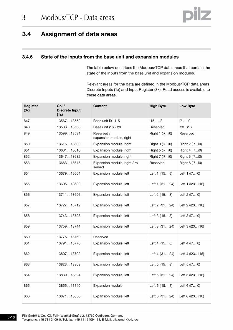
3.4.6 State of the inputs from the base unit and expansion modulesState of the inputs from the base unit and expansion modules3-ModbusTCP_Datenbereiche-Status Eingänge Basisgerät u Module-PNOZmulti
The table below describes the Modbus/TCP data areas that contain the
state of the inputs from the base unit and expansion modules.
Relevant areas for the data are defined in the Modbus/TCP data areas
Discrete Inputs (1x) and Input Register (3x). Read access is available to
these data areas.
Register
(3x)
Coil/
Discrete Input
(1x)
Content High Byte Low Byte
847 13567... 13552 Base unit i0 - i15 i15 ….i8 i7 ….i0
848 13583... 13568 Base unit i16 - 23 Reserved i23...i16
849 13599... 13584 Reserved /
expansion module, right
Right 1 (i7...i0) Reserved
850 13615... 13600 Expansion module, right Right 3 (i7...i0) Right 2 (i7...i0)
851 13631... 13616 Expansion module, right Right 5 (i7...i0) Right 4 (i7...i0)
852 13647... 13632 Expansion module, right Right 7 (i7...i0) Right 6 (i7...i0)
853 13663... 13648 Expansion module, right / re-
served
Reserved Right 8 (i7...i0)
854 13679... 13664 Expansion module, left Left 1 (i15…i8) Left 1 (i7…i0)
855 13695... 13680 Expansion module, left Left 1 (i31…i24) Left 1 (i23…i16)
856 13711... 13696 Expansion module, left Left 2 (i15…i8) Left 2 (i7…i0)
857 13727... 13712 Expansion module, left Left 2 (i31…i24) Left 2 (i23…i16)
858 13743... 13728 Expansion module, left Left 3 (i15…i8) Left 3 (i7…i0)
859 13759... 13744 Expansion module, left Left 3 (i31…i24) Left 3 (i23…i16)
860 13775... 13760 Reserved
861 13791... 13776 Expansion module, left Left 4 (i15…i8) Left 4 (i7…i0)
862 13807... 13792 Expansion module, left Left 4 (i31…i24) Left 4 (i23…i16)
863 13823... 13808 Expansion module, left Left 5 (i15…i8) Left 5 (i7…i0)
864 13839... 13824 Expansion module, left Left 5 (i31…i24) Left 5 (i23…i16)
865 13855... 13840 Expansion module Left 6 (i15…i8) Left 6 (i7…i0)
866 13871... 13856 Expansion module, left Left 6 (i31…i24) Left 6 (i23…i16)
Pilz GmbH & Co. KG, Felix-Wankel-Straße 2, 73760 Ostfildern, Germany
Telephone: +49 711 3409-0, Telefax: +49 711 3409-133, E-Mail: [email protected]
3.4 Assignment of data areas
3 Modbus/TCP - Data areas
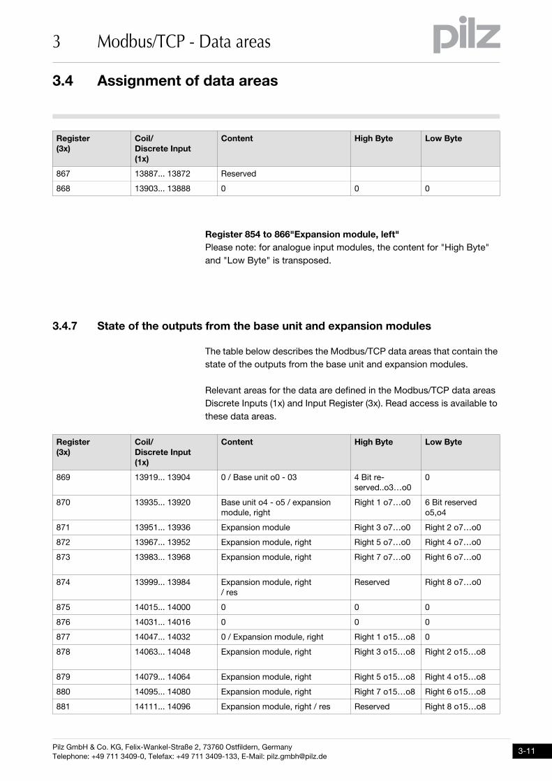
Register 854 to 866"Expansion module, left"
Please note: for analogue input modules, the content for "High Byte"
and "Low Byte" is transposed.
3.4.7 State of the outputs from the base unit and expansion modulesState of the outputs from the base unit and expansion modules3-ModbusTCP_Datenbereiche-Status Ausgänge Basisgerät u Module-PNOZmulti
The table below describes the Modbus/TCP data areas that contain the
state of the outputs from the base unit and expansion modules.
Relevant areas for the data are defined in the Modbus/TCP data areas
Discrete Inputs (1x) and Input Register (3x). Read access is available to
these data areas.
867 13887... 13872 Reserved
868 13903... 13888 0 0 0
Register
(3x)
Coil/
Discrete Input
(1x)
Content High Byte Low Byte
869 13919... 13904 0 / Base unit o0 - 03 4 Bit re-
served..o3…o0
0
870 13935... 13920 Base unit o4 - o5 / expansion
module, right
Right 1 o7…o0 6 Bit reserved
o5,o4
871 13951... 13936 Expansion module Right 3 o7…o0 Right 2 o7…o0
872 13967... 13952 Expansion module, right Right 5 o7…o0 Right 4 o7…o0
873 13983... 13968 Expansion module, right Right 7 o7…o0 Right 6 o7…o0
874 13999... 13984 Expansion module, right
/ res
Reserved Right 8 o7…o0
875 14015... 14000 0 0 0
876 14031... 14016 0 0 0
877 14047... 14032 0 / Expansion module, right Right 1 o15…o8 0
878 14063... 14048 Expansion module, right Right 3 o15…o8 Right 2 o15…o8
879 14079... 14064 Expansion module, right Right 5 o15…o8 Right 4 o15…o8
880 14095... 14080 Expansion module, right Right 7 o15…o8 Right 6 o15…o8
881 14111... 14096 Expansion module, right / res Reserved Right 8 o15…o8
Register
(3x)
Coil/
Discrete Input
(1x)
Content High Byte Low Byte
3.4 Assignment of data areas
3 Modbus/TCP - Data areas
Pilz GmbH & Co. KG, Felix-Wankel-Straße 2, 73760 Ostfildern, Germany
Telephone: +49 711 3409-0, Telefax: +49 711 3409-133, E-Mail: [email protected]
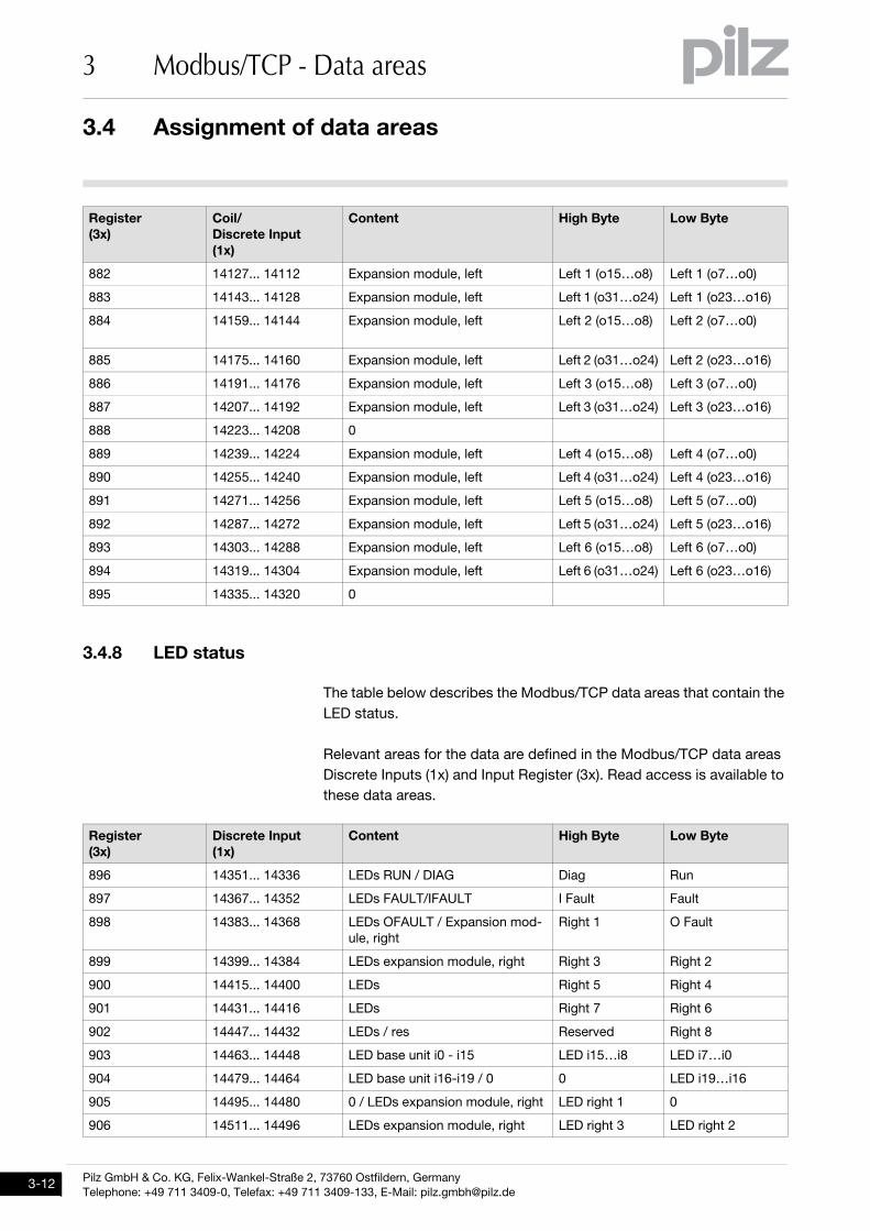
3.4.8 LED statusLED status3-ModbusTCP_Datenbereiche-Status-LEDs
The table below describes the Modbus/TCP data areas that contain the
LED status.
Relevant areas for the data are defined in the Modbus/TCP data areas
Discrete Inputs (1x) and Input Register (3x). Read access is available to
these data areas.
882 14127... 14112 Expansion module, left Left 1 (o15…o8) Left 1 (o7…o0)
883 14143... 14128 Expansion module, left Left 1 (o31…o24) Left 1 (o23…o16)
884 14159... 14144 Expansion module, left Left 2 (o15…o8) Left 2 (o7…o0)
885 14175... 14160 Expansion module, left Left 2 (o31…o24) Left 2 (o23…o16)
886 14191... 14176 Expansion module, left Left 3 (o15…o8) Left 3 (o7…o0)
887 14207... 14192 Expansion module, left Left 3 (o31…o24) Left 3 (o23…o16)
888 14223... 14208 0
889 14239... 14224 Expansion module, left Left 4 (o15…o8) Left 4 (o7…o0)
890 14255... 14240 Expansion module, left Left 4 (o31…o24) Left 4 (o23…o16)
891 14271... 14256 Expansion module, left Left 5 (o15…o8) Left 5 (o7…o0)
892 14287... 14272 Expansion module, left Left 5 (o31…o24) Left 5 (o23…o16)
893 14303... 14288 Expansion module, left Left 6 (o15…o8) Left 6 (o7…o0)
894 14319... 14304 Expansion module, left Left 6 (o31…o24) Left 6 (o23…o16)
895 14335... 14320 0
Register
(3x)
Discrete Input
(1x)
Content High Byte Low Byte
896 14351... 14336 LEDs RUN / DIAG Diag Run
897 14367... 14352 LEDs FAULT/IFAULT I Fault Fault
898 14383... 14368 LEDs OFAULT / Expansion mod-
ule, right
Right 1 O Fault
899 14399... 14384 LEDs expansion module, right Right 3 Right 2
900 14415... 14400 LEDs Right 5 Right 4
901 14431... 14416 LEDs Right 7 Right 6
902 14447... 14432 LEDs / res Reserved Right 8
903 14463... 14448 LED base unit i0 - i15 LED i15…i8 LED i7…i0
904 14479... 14464 LED base unit i16-i19 / 0 0 LED i19…i16
905 14495... 14480 0 / LEDs expansion module, right LED right 1 0
906 14511... 14496 LEDs expansion module, right LED right 3 LED right 2
Register
(3x)
Coil/
Discrete Input
(1x)
Content High Byte Low Byte
Pilz GmbH & Co. KG, Felix-Wankel-Straße 2, 73760 Ostfildern, Germany
Telephone: +49 711 3409-0, Telefax: +49 711 3409-133, E-Mail: [email protected]
3.4 Assignment of data areas
3 Modbus/TCP - Data areas
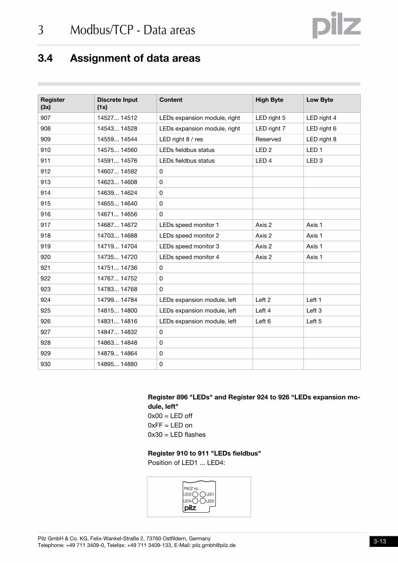
Register 896 "LEDs" and Register 924 to 926 “LEDs expansion mo-
dule, left"
0x00 = LED off
0xFF = LED on
0x30 = LED flashes
Register 910 to 911 "LEDs fieldbus"
Position of LED1 ... LED4:
907 14527... 14512 LEDs expansion module, right LED right 5 LED right 4
908 14543... 14528 LEDs expansion module, right LED right 7 LED right 6
909 14559... 14544 LED right 8 / res Reserved LED right 8
910 14575... 14560 LEDs fieldbus status LED 2 LED 1
911 14591... 14576 LEDs fieldbus status LED 4 LED 3
912 14607... 14592 0
913 14623... 14608 0
914 14639... 14624 0
915 14655... 14640 0
916 14671... 14656 0
917 14687... 14672 LEDs speed monitor 1 Axis 2 Axis 1
918 14703... 14688 LEDs speed monitor 2 Axis 2 Axis 1
919 14719... 14704 LEDs speed monitor 3 Axis 2 Axis 1
920 14735... 14720 LEDs speed monitor 4 Axis 2 Axis 1
921 14751... 14736 0
922 14767... 14752 0
923 14783... 14768 0
924 14799... 14784 LEDs expansion module, left Left 2 Left 1
925 14815... 14800 LEDs expansion module, left Left 4 Left 3
926 14831... 14816 LEDs expansion module, left Left 6 Left 5
927 14847... 14832 0
928 14863... 14848 0
929 14879... 14864 0
930 14895... 14880 0
Register
(3x)
Discrete Input
(1x)
Content High Byte Low Byte
�$%&�'�(((
�")*
�")!�")�
�")+
3.4 Assignment of data areas
3 Modbus/TCP - Data areas
Pilz GmbH & Co. KG, Felix-Wankel-Straße 2, 73760 Ostfildern, Germany
Telephone: +49 711 3409-0, Telefax: +49 711 3409-133, E-Mail: [email protected]
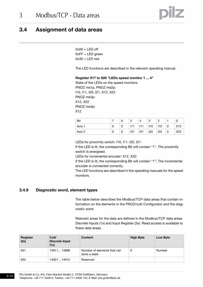
0x00 = LED off
0xFF = LED green
0x30 = LED red
The LED functions are described in the relevant operating manual.
Register 917 to 920 "LEDs speed monitor 1 ... 4"
State of the LEDs on the speed monitors
PNOZ ms1p, PNOZ ms2p:
I10, I11, I20, I21, X12, X22
PNOZ ms3p:
X12, X22
PNOZ ms4p:
X12
LEDs for proximity switch: I10, I11, I20, I21:
If the LED is lit, the corresponding Bit will contain “1”. The proximity
switch is energised.
LEDs for incremental encoder: X12, X22:
If the LED is lit, the corresponding Bit will contain “1”; The incremental
encoder is connected correctly.
The LED functions are described in the operating manuals for the speed
monitors.
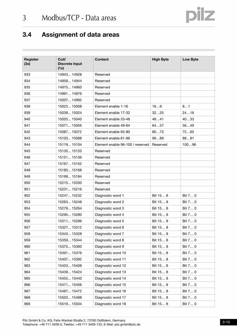
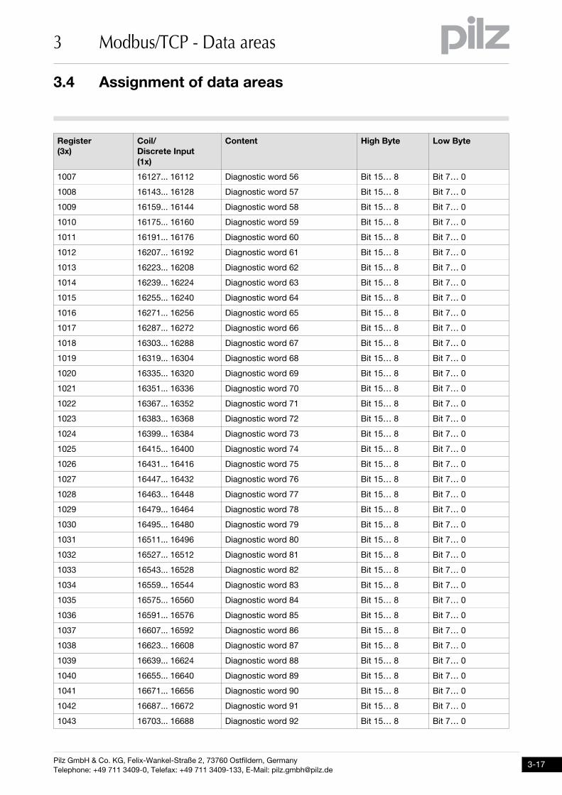
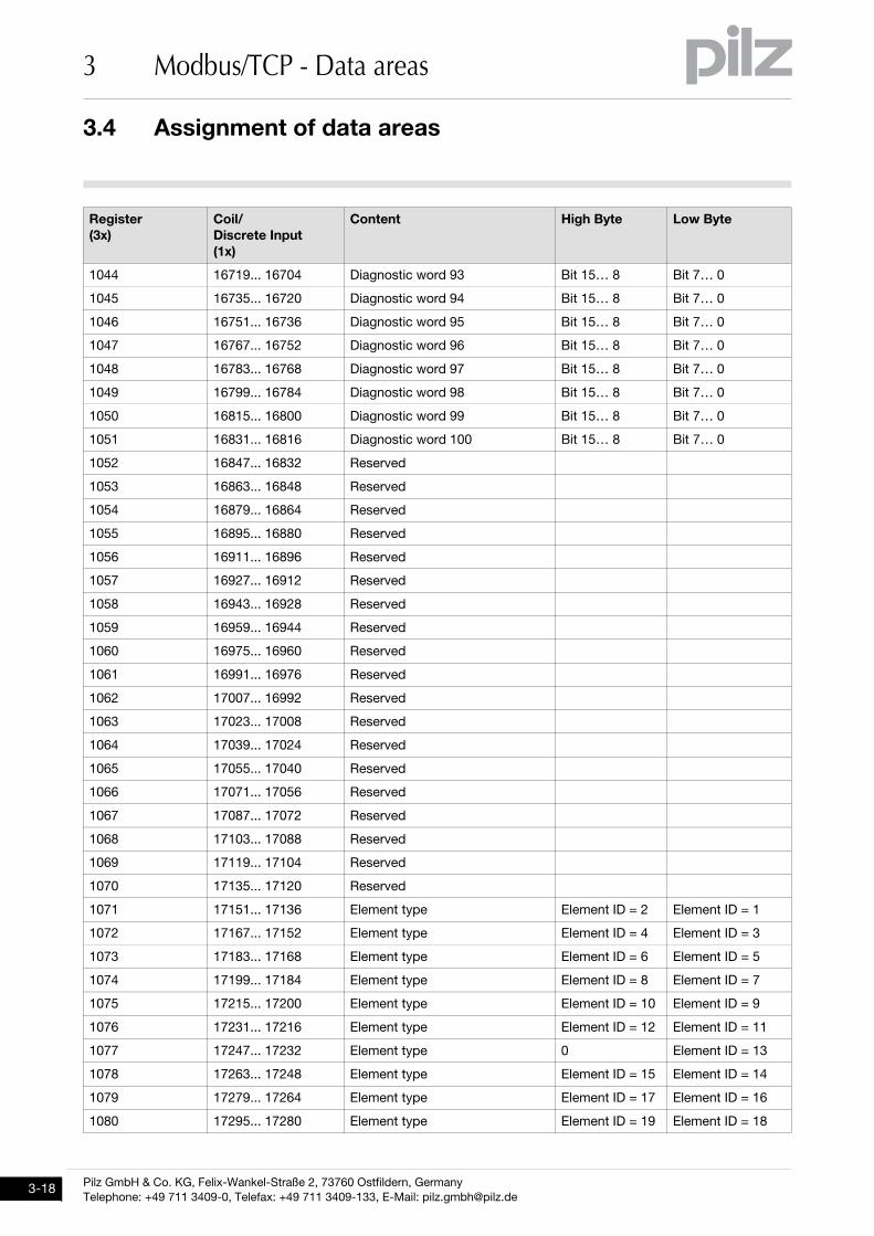
3.4.9 Diagnostic word, element typesDiagnostic word, element types3-ModbusTCP_Datenbereiche-Diagnosewort-Elementtypen
The table below describes the Modbus/TCP data areas that contain in-
formation on the elements in the PNOZmulti Configurator and the diag-
nostic word.
Relevant areas for the data are defined in the Modbus/TCP data areas
Discrete Inputs (1x) and Input Register (3x). Read access is available to
these data areas.
Bit 7 6 5 4 3 2 1 0
Axis 1 0 0 I11 I11 I10 I10 0 X12
Axis 2 0 0 I21 I21 I20 I20 0 X22
Register
(3x)
Coil/
Discrete Input
(1x)
Content High Byte Low Byte
931 14911... 14896 Number of elements that can
store a state
0 Number
932 14927... 14912 Reserved
Pilz GmbH & Co. KG, Felix-Wankel-Straße 2, 73760 Ostfildern, Germany
Telephone: +49 711 3409-0, Telefax: +49 711 3409-133, E-Mail: [email protected]
3.4 Assignment of data areas
3 Modbus/TCP - Data areas
933 14943... 14928 Reserved
934 14959... 14944 Reserved
935 14975... 14960 Reserved
936 14991... 14976 Reserved
937 15007... 14992 Reserved
938 15023... 15008 Element enable 1-16 16…9 8…1
939 15039... 15024 Element enable 17-32 32…25 24…16
940 15055... 15040 Element enable 33-48 48…41 40…33
941 15071... 15056 Element enable 49-64 64…57 56…49
942 15087... 15072 Element enable 65-80 80…73 72…65
943 15103... 15088 Element enable 81-96 96…89 88…81
944 15119... 15104 Element enable 96-100 / reserved Reserved 100…96
945 15135... 15120 Reserved
946 15151... 15136 Reserved
947 15167... 15152 Reserved
948 15183... 15168 Reserved
949 15199... 15184 Reserved
950 15215... 15200 Reserved
951 15231... 15216 Reserved
952 15247... 15232 Diagnostic word 1 Bit 15… 8 Bit 7… 0
953 15263... 15248 Diagnostic word 2 Bit 15… 8 Bit 7… 0
954 15279... 15264 Diagnostic word 3 Bit 15… 8 Bit 7… 0
955 15295... 15280 Diagnostic word 4 Bit 15… 8 Bit 7… 0
956 15311... 15296 Diagnostic word 5 Bit 15… 8 Bit 7… 0
957 15327... 15312 Diagnostic word 6 Bit 15… 8 Bit 7… 0
958 15343... 15328 Diagnostic word 7 Bit 15… 8 Bit 7… 0
959 15359... 15344 Diagnostic word 8 Bit 15… 8 Bit 7… 0
960 15375... 15360 Diagnostic word 9 Bit 15… 8 Bit 7… 0
961 15391... 15376 Diagnostic word 10 Bit 15… 8 Bit 7… 0
962 15407... 15392 Diagnostic word 11 Bit 15… 8 Bit 7… 0
963 15423... 15408 Diagnostic word 12 Bit 15… 8 Bit 7… 0
964 15439... 15424 Diagnostic word 13 Bit 15… 8 Bit 7… 0
965 15455... 15440 Diagnostic word 14 Bit 15… 8 Bit 7… 0
966 15471... 15456 Diagnostic word 15 Bit 15… 8 Bit 7… 0
967 15487... 15472 Diagnostic word 16 Bit 15… 8 Bit 7… 0
968 15503... 15488 Diagnostic word 17 Bit 15… 8 Bit 7… 0
969 15519... 15504 Diagnostic word 18 Bit 15… 8 Bit 7… 0
Register
(3x)
Coil/
Discrete Input
(1x)
Content High Byte Low Byte
3.4 Assignment of data areas
3 Modbus/TCP - Data areas
Pilz GmbH & Co. KG, Felix-Wankel-Straße 2, 73760 Ostfildern, Germany
Telephone: +49 711 3409-0, Telefax: +49 711 3409-133, E-Mail: [email protected]
970 15535... 15520 Diagnostic word 19 Bit 15… 8 Bit 7… 0
971 15551... 15536 Diagnostic word 20 Bit 15… 8 Bit 7… 0
972 15567... 15552 Diagnostic word 21 Bit 15… 8 Bit 7… 0
973 15583... 15568 Diagnostic word 22 Bit 15… 8 Bit 7… 0
974 15599... 15584 Diagnostic word 23 Bit 15… 8 Bit 7… 0
975 15615... 15600 Diagnostic word 24 Bit 15… 8 Bit 7… 0
976 15631... 15616 Diagnostic word 25 Bit 15… 8 Bit 7… 0
977 15647... 15632 Diagnostic word 26 Bit 15… 8 Bit 7… 0
978 15663... 15648 Diagnostic word 27 Bit 15… 8 Bit 7… 0
979 15679... 15664 Diagnostic word 28 Bit 15… 8 Bit 7… 0
980 15695... 15680 Diagnostic word 29 Bit 15… 8 Bit 7… 0
981 15711... 15696 Diagnostic word 30 Bit 15… 8 Bit 7… 0
982 15727... 15712 Diagnostic word 31 Bit 15… 8 Bit 7… 0
983 15743... 15728 Diagnostic word 32 Bit 15… 8 Bit 7… 0
984 15759... 15744 Diagnostic word 33 Bit 15… 8 Bit 7… 0
985 15775... 15760 Diagnostic word 34 Bit 15… 8 Bit 7… 0
986 15791... 15776 Diagnostic word 35 Bit 15… 8 Bit 7… 0
987 15807... 15792 Diagnostic word 36 Bit 15… 8 Bit 7… 0
988 15823... 15808 Diagnostic word 37 Bit 15… 8 Bit 7… 0
989 15839... 15824 Diagnostic word 38 Bit 15… 8 Bit 7… 0
990 15855... 15840 Diagnostic word 39 Bit 15… 8 Bit 7… 0
991 15871... 15856 Diagnostic word 40 Bit 15… 8 Bit 7… 0
992 15887... 15872 Diagnostic word 41 Bit 15… 8 Bit 7… 0
993 15903... 15888 Diagnostic word 42 Bit 15… 8 Bit 7… 0
994 15919... 15904 Diagnostic word 43 Bit 15… 8 Bit 7… 0
995 15935... 15920 Diagnostic word 44 Bit 15… 8 Bit 7… 0
996 15951... 15936 Diagnostic word 45 Bit 15… 8 Bit 7… 0
997 15967... 15952 Diagnostic word 46 Bit 15… 8 Bit 7… 0
998 15983... 15968 Diagnostic word 47 Bit 15… 8 Bit 7… 0
999 15999... 15984 Diagnostic word 48 Bit 15… 8 Bit 7… 0
1000 16015... 16000 Diagnostic word 49 Bit 15… 8 Bit 7… 0
1001 16031... 16016 Diagnostic word 50 Bit 15… 8 Bit 7… 0
1002 16047... 16032 Diagnostic word 51 Bit 15… 8 Bit 7… 0
1003 16063... 16048 Diagnostic word 52 Bit 15… 8 Bit 7… 0
1004 16079... 16064 Diagnostic word 53 Bit 15… 8 Bit 7… 0
1005 16095... 16080 Diagnostic word 54 Bit 15… 8 Bit 7… 0
1006 16111... 16096 Diagnostic word 55 Bit 15… 8 Bit 7… 0
Register
(3x)
Coil/
Discrete Input
(1x)
Content High Byte Low Byte
Pilz GmbH & Co. KG, Felix-Wankel-Straße 2, 73760 Ostfildern, Germany
Telephone: +49 711 3409-0, Telefax: +49 711 3409-133, E-Mail: [email protected]
3.4 Assignment of data areas
3 Modbus/TCP - Data areas
1007 16127... 16112 Diagnostic word 56 Bit 15… 8 Bit 7… 0
1008 16143... 16128 Diagnostic word 57 Bit 15… 8 Bit 7… 0
1009 16159... 16144 Diagnostic word 58 Bit 15… 8 Bit 7… 0
1010 16175... 16160 Diagnostic word 59 Bit 15… 8 Bit 7… 0
1011 16191... 16176 Diagnostic word 60 Bit 15… 8 Bit 7… 0
1012 16207... 16192 Diagnostic word 61 Bit 15… 8 Bit 7… 0
1013 16223... 16208 Diagnostic word 62 Bit 15… 8 Bit 7… 0
1014 16239... 16224 Diagnostic word 63 Bit 15… 8 Bit 7… 0
1015 16255... 16240 Diagnostic word 64 Bit 15… 8 Bit 7… 0
1016 16271... 16256 Diagnostic word 65 Bit 15… 8 Bit 7… 0
1017 16287... 16272 Diagnostic word 66 Bit 15… 8 Bit 7… 0
1018 16303... 16288 Diagnostic word 67 Bit 15… 8 Bit 7… 0
1019 16319... 16304 Diagnostic word 68 Bit 15… 8 Bit 7… 0
1020 16335... 16320 Diagnostic word 69 Bit 15… 8 Bit 7… 0
1021 16351... 16336 Diagnostic word 70 Bit 15… 8 Bit 7… 0
1022 16367... 16352 Diagnostic word 71 Bit 15… 8 Bit 7… 0
1023 16383... 16368 Diagnostic word 72 Bit 15… 8 Bit 7… 0
1024 16399... 16384 Diagnostic word 73 Bit 15… 8 Bit 7… 0
1025 16415... 16400 Diagnostic word 74 Bit 15… 8 Bit 7… 0
1026 16431... 16416 Diagnostic word 75 Bit 15… 8 Bit 7… 0
1027 16447... 16432 Diagnostic word 76 Bit 15… 8 Bit 7… 0
1028 16463... 16448 Diagnostic word 77 Bit 15… 8 Bit 7… 0
1029 16479... 16464 Diagnostic word 78 Bit 15… 8 Bit 7… 0
1030 16495... 16480 Diagnostic word 79 Bit 15… 8 Bit 7… 0
1031 16511... 16496 Diagnostic word 80 Bit 15… 8 Bit 7… 0
1032 16527... 16512 Diagnostic word 81 Bit 15… 8 Bit 7… 0
1033 16543... 16528 Diagnostic word 82 Bit 15… 8 Bit 7… 0
1034 16559... 16544 Diagnostic word 83 Bit 15… 8 Bit 7… 0
1035 16575... 16560 Diagnostic word 84 Bit 15… 8 Bit 7… 0
1036 16591... 16576 Diagnostic word 85 Bit 15… 8 Bit 7… 0
1037 16607... 16592 Diagnostic word 86 Bit 15… 8 Bit 7… 0
1038 16623... 16608 Diagnostic word 87 Bit 15… 8 Bit 7… 0
1039 16639... 16624 Diagnostic word 88 Bit 15… 8 Bit 7… 0
1040 16655... 16640 Diagnostic word 89 Bit 15… 8 Bit 7… 0
1041 16671... 16656 Diagnostic word 90 Bit 15… 8 Bit 7… 0
1042 16687... 16672 Diagnostic word 91 Bit 15… 8 Bit 7… 0
1043 16703... 16688 Diagnostic word 92 Bit 15… 8 Bit 7… 0
Register
(3x)
Coil/
Discrete Input
(1x)
Content High Byte Low Byte
3.4 Assignment of data areas
3 Modbus/TCP - Data areas
Pilz GmbH & Co. KG, Felix-Wankel-Straße 2, 73760 Ostfildern, Germany
Telephone: +49 711 3409-0, Telefax: +49 711 3409-133, E-Mail: [email protected]
1044 16719... 16704 Diagnostic word 93 Bit 15… 8 Bit 7… 0
1045 16735... 16720 Diagnostic word 94 Bit 15… 8 Bit 7… 0
1046 16751... 16736 Diagnostic word 95 Bit 15… 8 Bit 7… 0
1047 16767... 16752 Diagnostic word 96 Bit 15… 8 Bit 7… 0
1048 16783... 16768 Diagnostic word 97 Bit 15… 8 Bit 7… 0
1049 16799... 16784 Diagnostic word 98 Bit 15… 8 Bit 7… 0
1050 16815... 16800 Diagnostic word 99 Bit 15… 8 Bit 7… 0
1051 16831... 16816 Diagnostic word 100 Bit 15… 8 Bit 7… 0
1052 16847... 16832 Reserved
1053 16863... 16848 Reserved
1054 16879... 16864 Reserved
1055 16895... 16880 Reserved
1056 16911... 16896 Reserved
1057 16927... 16912 Reserved
1058 16943... 16928 Reserved
1059 16959... 16944 Reserved
1060 16975... 16960 Reserved
1061 16991... 16976 Reserved
1062 17007... 16992 Reserved
1063 17023... 17008 Reserved
1064 17039... 17024 Reserved
1065 17055... 17040 Reserved
1066 17071... 17056 Reserved
1067 17087... 17072 Reserved
1068 17103... 17088 Reserved
1069 17119... 17104 Reserved
1070 17135... 17120 Reserved
1071 17151... 17136 Element type Element ID = 2 Element ID = 1
1072 17167... 17152 Element type Element ID = 4 Element ID = 3
1073 17183... 17168 Element type Element ID = 6 Element ID = 5
1074 17199... 17184 Element type Element ID = 8 Element ID = 7
1075 17215... 17200 Element type Element ID = 10 Element ID = 9
1076 17231... 17216 Element type Element ID = 12 Element ID = 11
1077 17247... 17232 Element type 0 Element ID = 13
1078 17263... 17248 Element type Element ID = 15 Element ID = 14
1079 17279... 17264 Element type Element ID = 17 Element ID = 16
1080 17295... 17280 Element type Element ID = 19 Element ID = 18
Register
(3x)
Coil/
Discrete Input
(1x)
Content High Byte Low Byte
Pilz GmbH & Co. KG, Felix-Wankel-Straße 2, 73760 Ostfildern, Germany
Telephone: +49 711 3409-0, Telefax: +49 711 3409-133, E-Mail: [email protected]
3.4 Assignment of data areas
3 Modbus/TCP - Data areas
1081 17311... 17296 Element type Element ID = 21 Element ID = 20
1082 17327... 17312 Element type Element ID = 23 Element ID = 22
1083 17343... 17328 Element type Element ID = 25 Element ID = 24
1084 17359... 17344 Element type 0 Element ID = 26
1085 17375... 17360 Element type Element ID = 15 Element ID = 27
1086 17391... 17376 Element type Element ID = 17 Element ID = 29
1087 17407... 17392 Element type Element ID = 19 Element ID = 31
1088 17423... 17408 Element type Element ID = 21 Element ID = 33
1089 17439... 17424 Element type Element ID = 23 Element ID = 35
1090 17455... 17440 Element type Element ID = 25 Element ID = 37
1091 17471... 17456 Element type 0 Element ID = 39
1092 17487... 17472 Element type Element ID = 41 Element ID = 40
1093 17503... 17488 Element type Element ID = 43 Element ID = 42
1094 17519... 17504 Element type Element ID = 45 Element ID = 44
1095 17535... 17520 Element type Element ID = 47 Element ID = 46
1096 17551... 17536 Element type Element ID = 49 Element ID = 48
1097 17567... 17552 Element type Element ID = 51 Element ID = 50
1098 17583... 17568 Element type 0 Element ID = 52
1099 17599... 17584 Element type Element ID = 54 Element ID = 53
1100 17615... 17600 Element type Element ID = 56 Element ID = 55
1101 17631... 17616 Element type Element ID = 58 Element ID = 57
1102 17647... 17632 Element type Element ID = 60 Element ID = 59
1103 17663... 17648 Element type Element ID = 62 Element ID = 61
1104 17679... 17664 Element type Element ID = 64 Element ID = 63
1105 17695... 17680 Element type 0 Element ID = 65
1106 17711... 17696 Element type Element ID = 67 Element ID = 66
1107 17727... 17712 Element type Element ID = 69 Element ID = 68
1108 17743... 17728 Element type Element ID = 71 Element ID = 70
1109 17759... 17744 Element type Element ID = 73 Element ID = 72
1110 17775... 17760 Element type Element ID = 75 Element ID = 74
1111 17791... 17776 Element type Element ID = 77 Element ID = 76
1112 17807... 17792 Element type 0 Element ID = 78
1113 17823... 17808 Element type Element ID = 80 Element ID = 79
1114 17839... 17824 Element type Element ID = 82 Element ID = 81
1115 17855... 17840 Element type Element ID = 84 Element ID = 83
1116 17871... 17856 Element type Element ID = 86 Element ID = 85
1117 17887... 17872 Element type Element ID = 88 Element ID = 87
Register
(3x)
Coil/
Discrete Input
(1x)
Content High Byte Low Byte
3.4 Assignment of data areas
3 Modbus/TCP - Data areas
Pilz GmbH & Co. KG, Felix-Wankel-Straße 2, 73760 Ostfildern, Germany
Telephone: +49 711 3409-0, Telefax: +49 711 3409-133, E-Mail: [email protected]
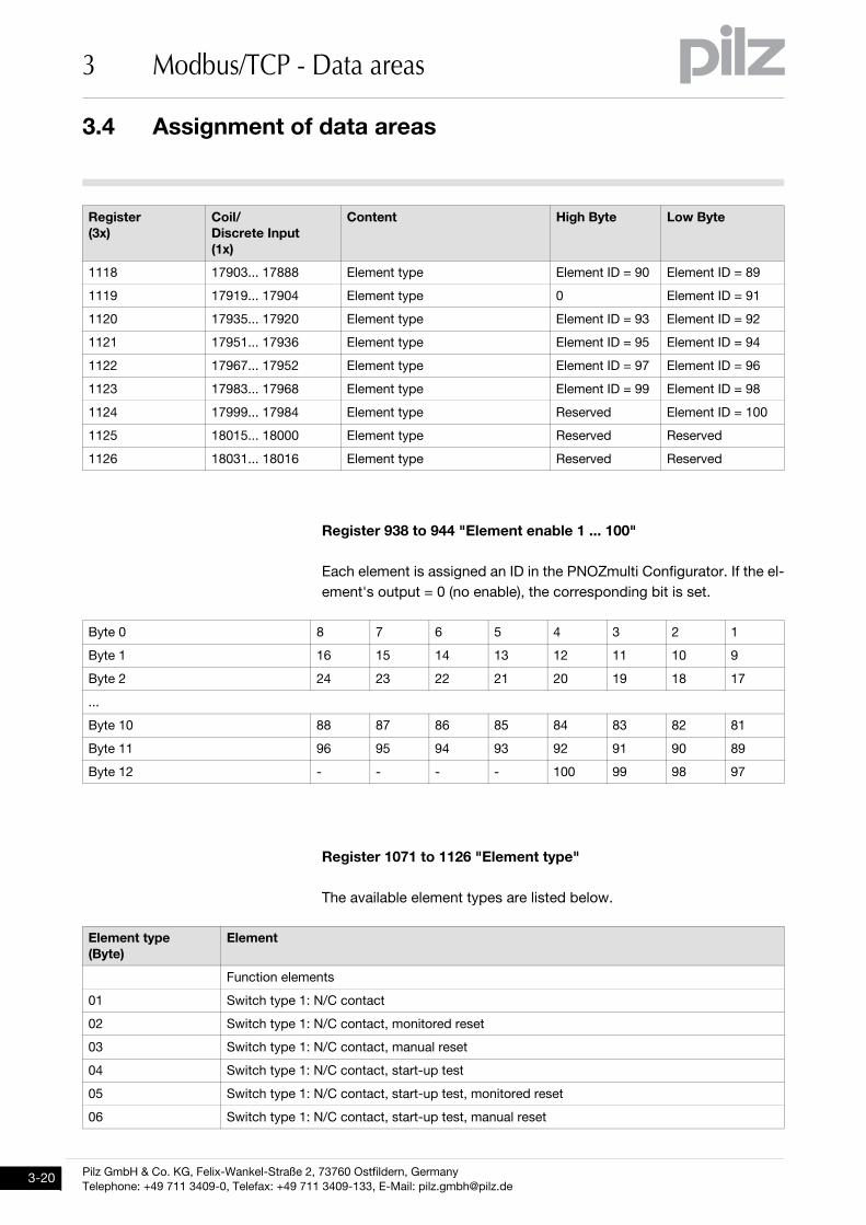
Register 938 to 944 "Element enable 1 ... 100"
Each element is assigned an ID in the PNOZmulti Configurator. If the el-
ement's output = 0 (no enable), the corresponding bit is set.
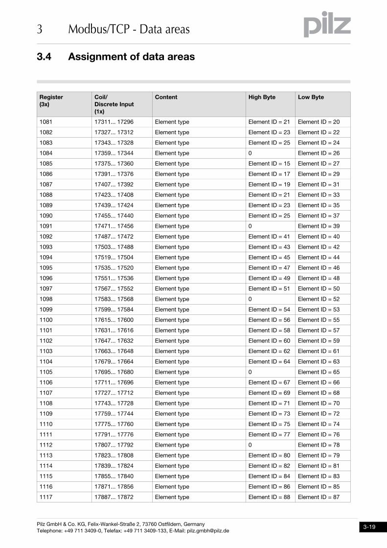
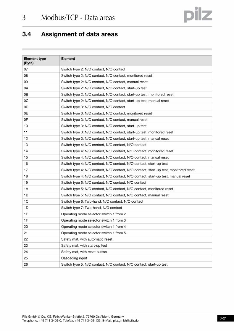
Register 1071 to 1126 "Element type"
The available element types are listed below.
1118 17903... 17888 Element type Element ID = 90 Element ID = 89
1119 17919... 17904 Element type 0 Element ID = 91
1120 17935... 17920 Element type Element ID = 93 Element ID = 92
1121 17951... 17936 Element type Element ID = 95 Element ID = 94
1122 17967... 17952 Element type Element ID = 97 Element ID = 96
1123 17983... 17968 Element type Element ID = 99 Element ID = 98
1124 17999... 17984 Element type Reserved Element ID = 100
1125 18015... 18000 Element type Reserved Reserved
1126 18031... 18016 Element type Reserved Reserved
Byte 0 8 7 6 5 4 3 2 1
Byte 1 16 15 14 13 12 11 10 9
Byte 2 24 23 22 21 20 19 18 17
...
Byte 10 88 87 86 85 84 83 82 81
Byte 11 96 95 94 93 92 91 90 89
Byte 12 - - - - 100 99 98 97
Element type
(Byte)
Element
Function elements
01 Switch type 1: N/C contact
02 Switch type 1: N/C contact, monitored reset
03 Switch type 1: N/C contact, manual reset
04 Switch type 1: N/C contact, start-up test
05 Switch type 1: N/C contact, start-up test, monitored reset
06 Switch type 1: N/C contact, start-up test, manual reset
Register
(3x)
Coil/
Discrete Input
(1x)
Content High Byte Low Byte
Pilz GmbH & Co. KG, Felix-Wankel-Straße 2, 73760 Ostfildern, Germany
Telephone: +49 711 3409-0, Telefax: +49 711 3409-133, E-Mail: [email protected]
3.4 Assignment of data areas
3 Modbus/TCP - Data areas
07 Switch type 2: N/C contact, N/O contact
08 Switch type 2: N/C contact, N/O contact, monitored reset
09 Switch type 2: N/C contact, N/O contact, manual reset
0A Switch type 2: N/C contact, N/O contact, start-up test
0B Switch type 2: N/C contact, N/O contact, start-up test, monitored reset
0C Switch type 2: N/C contact, N/O contact, start-up test, manual reset
0D Switch type 3: N/C contact, N/C contact
0E Switch type 3: N/C contact, N/C contact, monitored reset
0F Switch type 3: N/C contact, N/C contact, manual reset
10 Switch type 3: N/C contact, N/C contact, start-up test
11 Switch type 3: N/C contact, N/C contact, start-up test, monitored reset
12 Switch type 3: N/C contact, N/C contact, start-up test, manual reset
13 Switch type 4: N/C contact, N/C contact, N/O contact
14 Switch type 4: N/C contact, N/C contact, N/O contact, monitored reset
15 Switch type 4: N/C contact, N/C contact, N/O contact, manual reset
16 Switch type 4: N/C contact, N/C contact, N/O contact, start-up test
17 Switch type 4: N/C contact, N/C contact, N/O contact, start-up test, monitored reset
18 Switch type 4: N/C contact, N/C contact, N/O contact, start-up test, manual reset
19 Switch type 5: N/C contact, N/C contact, N/C contact
1A Switch type 5: N/C contact, N/C contact, N/C contact, monitored reset
1B Switch type 5: N/C contact, N/C contact, N/C contact, manual reset
1C Switch type 6: Two-hand, N/C contact, N/O contact
1D Switch type 7: Two-hand, N/O contact
1E Operating mode selector switch 1 from 2
1F Operating mode selector switch 1 from 3
20 Operating mode selector switch 1 from 4
21 Operating mode selector switch 1 from 5
22 Safety mat, with automatic reset
23 Safety mat, with start-up test
24 Safety mat, with reset button
25 Cascading input
26 Switch type 5, N/C contact, N/C contact, N/C contact, start-up test
Element type
(Byte)
Element
3.4 Assignment of data areas
3 Modbus/TCP - Data areas
Pilz GmbH & Co. KG, Felix-Wankel-Straße 2, 73760 Ostfildern, Germany
Telephone: +49 711 3409-0, Telefax: +49 711 3409-133, E-Mail: [email protected]
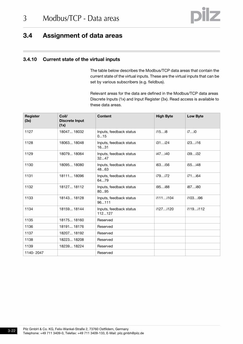
3.4.10 Current state of the virtual inputsCurrent state of the virtual inputs3-ModbusTCP_Datenbereiche-aktuelle Zustände der virtuellen Eingänge
The table below describes the Modbus/TCP data areas that contain the
current state of the virtual inputs. These are the virtual inputs that can be
set by various subscribers (e.g. fieldbus).
Relevant areas for the data are defined in the Modbus/TCP data areas
Discrete Inputs (1x) and Input Register (3x). Read access is available to
these data areas.
Register
(3x)
Coil/
Discrete Input
(1x)
Content High Byte Low Byte
1127 18047... 18032 Inputs, feedback status
0...15
i15…i8 i7…i0
1128 18063... 18048 Inputs, feedback status
16...31
i31…i24 i23…i16
1129 18079... 18064 Inputs, feedback status
32...47
i47…i40 i39…i32
1130 18095... 18080 Inputs, feedback status
48...63
i63…i56 i55…i48
1131 18111... 18096 Inputs, feedback status
64...79
i79…i72 i71…i64
1132 18127... 18112 Inputs, feedback status
80...95
i95…i88 i87…i80
1133 18143... 18128 Inputs, feedback status
96...111
i111…i104 i103…i96
1134 18159... 18144 Inputs, feedback status
112...127
i127…i120 i119…i112
1135 18175... 18160 Reserved
1136 18191... 18176 Reserved
1137 18207... 18192 Reserved
1138 18223... 18208 Reserved
1139 18239... 18224 Reserved
1140- 2047 Reserved
Pilz GmbH & Co. KG, Felix-Wankel-Straße 2, 73760 Ostfildern, Germany
Telephone: +49 711 3409-0, Telefax: +49 711 3409-133, E-Mail: [email protected]
3.4 Assignment of data areas
3 Modbus/TCP - Data areas
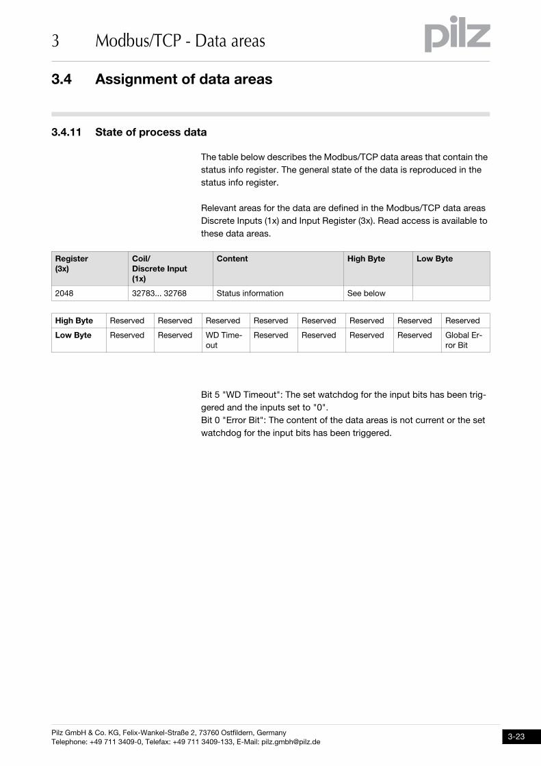
3.4.11 State of process dataState of process data3-ModbusTCP_Datenbereiche-Zustand der Prozessdaten
The table below describes the Modbus/TCP data areas that contain the
status info register. The general state of the data is reproduced in the
status info register.
Relevant areas for the data are defined in the Modbus/TCP data areas
Discrete Inputs (1x) and Input Register (3x). Read access is available to
these data areas.
Bit 5 "WD Timeout": The set watchdog for the input bits has been trig-
gered and the inputs set to "0".
Bit 0 "Error Bit": The content of the data areas is not current or the set
watchdog for the input bits has been triggered.
Register
(3x)
Coil/
Discrete Input
(1x)
Content High Byte Low Byte
2048 32783... 32768 Status information See below
High Byte Reserved Reserved Reserved Reserved Reserved Reserved Reserved Reserved
Low Byte Reserved Reserved WD Time-
out
Reserved Reserved Reserved Reserved Global Er-
ror Bit
3.5 Updating the data areas
3 Modbus/TCP - Data areas
Pilz GmbH & Co. KG, Felix-Wankel-Straße 2, 73760 Ostfildern, Germany
Telephone: +49 711 3409-0, Telefax: +49 711 3409-133, E-Mail: [email protected]
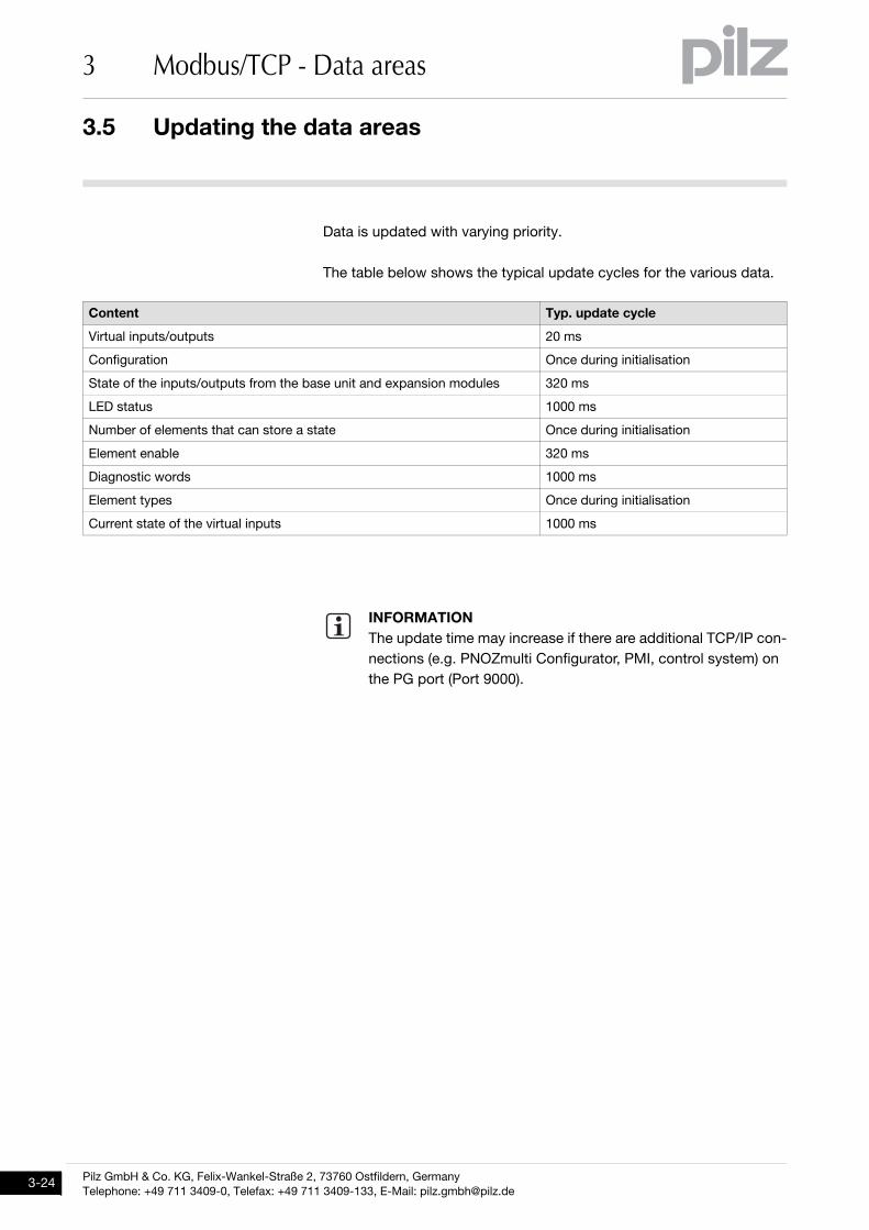
3.5Updating the data areas3500Updating the data areas3-ModbusTCP_Aktualisierung der Datenbereiche-PNOZmulti
Data is updated with varying priority.
The table below shows the typical update cycles for the various data.
Content Typ. update cycle
Virtual inputs/outputs 20 ms
Configuration Once during initialisation
State of the inputs/outputs from the base unit and expansion modules 320 ms
LED status 1000 ms
Number of elements that can store a state Once during initialisation
Element enable 320 ms
Diagnostic words 1000 ms
Element types Once during initialisation
Current state of the virtual inputs 1000 ms
INFORMATION
The update time may increase if there are additional TCP/IP con-
nections (e.g. PNOZmulti Configurator, PMI, control system) on
the PG port (Port 9000).
Pilz GmbH & Co. KG, Felix-Wankel-Straße 2, 73760 Ostfildern, Germany
Telephone: +49 711 3409-0, Telefax: +49 711 3409-133, E-Mail: [email protected]
3.6 Bit addressing in a Register
3 Modbus/TCP - Data areas
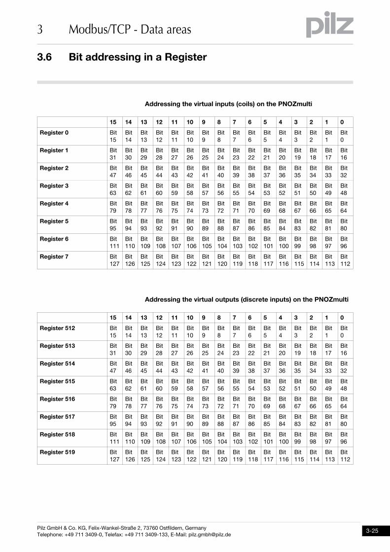
3.6Bit addressing in a Register3600Bit addressing in a Register3-ModbusTCP_Bit-Adressierung in einem Register-PNOZmulti
Addressing the virtual inputs (coils) on the PNOZmulti
Addressing the virtual outputs (discrete inputs) on the PNOZmulti
15 14 13 12 11 10 9 8 7 6 5 4 3 2 1 0
Register 0 Bit
15
Bit
14
Bit
13
Bit
12
Bit
11
Bit
10
Bit
9
Bit
8
Bit
7
Bit
6
Bit
5
Bit
4
Bit
3
Bit
2
Bit
1
Bit
0
Register 1 Bit
31
Bit
30
Bit
29
Bit
28
Bit
27
Bit
26
Bit
25
Bit
24
Bit
23
Bit
22
Bit
21
Bit
20
Bit
19
Bit
18
Bit
17
Bit
16
Register 2 Bit
47
Bit
46
Bit
45
Bit
44
Bit
43
Bit
42
Bit
41
Bit
40
Bit
39
Bit
38
Bit
37
Bit
36
Bit
35
Bit
34
Bit
33
Bit
32
Register 3 Bit
63
Bit
62
Bit
61
Bit
60
Bit
59
Bit
58
Bit
57
Bit
56
Bit
55
Bit
54
Bit
53
Bit
52
Bit
51
Bit
50
Bit
49
Bit
48
Register 4 Bit
79
Bit
78
Bit
77
Bit
76
Bit
75
Bit
74
Bit
73
Bit
72
Bit
71
Bit
70
Bit
69
Bit
68
Bit
67
Bit
66
Bit
65
Bit
64
Register 5 Bit
95
Bit
94
Bit
93
Bit
92
Bit
91
Bit
90
Bit
89
Bit
88
Bit
87
Bit
86
Bit
85
Bit
84
Bit
83
Bit
82
Bit
81
Bit
80
Register 6 Bit
111
Bit
110
Bit
109
Bit
108
Bit
107
Bit
106
Bit
105
Bit
104
Bit
103
Bit
102
Bit
101
Bit
100
Bit
99
Bit
98
Bit
97
Bit
96
Register 7 Bit
127
Bit
126
Bit
125
Bit
124
Bit
123
Bit
122
Bit
121
Bit
120
Bit
119
Bit
118
Bit
117
Bit
116
Bit
115
Bit
114
Bit
113
Bit
112
15 14 13 12 11 10 9 8 7 6 5 4 3 2 1 0
Register 512 Bit
15
Bit
14
Bit
13
Bit
12
Bit
11
Bit
10
Bit
9
Bit
8
Bit
7
Bit
6
Bit
5
Bit
4
Bit
3
Bit
2
Bit
1
Bit
0
Register 513 Bit
31
Bit
30
Bit
29
Bit
28
Bit
27
Bit
26
Bit
25
Bit
24
Bit
23
Bit
22
Bit
21
Bit
20
Bit
19
Bit
18
Bit
17
Bit
16
Register 514 Bit
47
Bit
46
Bit
45
Bit
44
Bit
43
Bit
42
Bit
41
Bit
40
Bit
39
Bit
38
Bit
37
Bit
36
Bit
35
Bit
34
Bit
33
Bit
32
Register 515 Bit
63
Bit
62
Bit
61
Bit
60
Bit
59
Bit
58
Bit
57
Bit
56
Bit
55
Bit
54
Bit
53
Bit
52
Bit
51
Bit
50
Bit
49
Bit
48
Register 516 Bit
79
Bit
78
Bit
77
Bit
76
Bit
75
Bit
74
Bit
73
Bit
72
Bit
71
Bit
70
Bit
69
Bit
68
Bit
67
Bit
66
Bit
65
Bit
64
Register 517 Bit
95
Bit
94
Bit
93
Bit
92
Bit
91
Bit
90
Bit
89
Bit
88
Bit
87
Bit
86
Bit
85
Bit
84
Bit
83
Bit
82
Bit
81
Bit
80
Register 518 Bit
111
Bit
110
Bit
109
Bit
108
Bit
107
Bit
106
Bit
105
Bit
104
Bit
103
Bit
102
Bit
101
Bit
100
Bit
99
Bit
98
Bit
97
Bit
96
Register 519 Bit
127
Bit
126
Bit
125
Bit
124
Bit
123
Bit
122
Bit
121
Bit
120
Bit
119
Bit
118
Bit
117
Bit
116
Bit
115
Bit
114
Bit
113
Bit
112
3 Modbus/TCP - Data areas
Pilz GmbH & Co. KG, Felix-Wankel-Straße 2, 73760 Ostfildern, Germany
Telephone: +49 711 3409-0, Telefax: +49 711 3409-133, E-Mail: [email protected]
Pilz GmbH & Co. KG, Felix-Wankel-Straße 2, 73760 Ostfildern, Germany
Telephone: +49 711 3409-0, Telefax: +49 711 3409-133, E-Mail: [email protected]
4.1 Modbus subscriber
4 Application example
44000Application exampleApplication example4-4.1Modbus subscriber4100Modbus subscriber4-ModbusTCP_Bsp_Teilnehmer
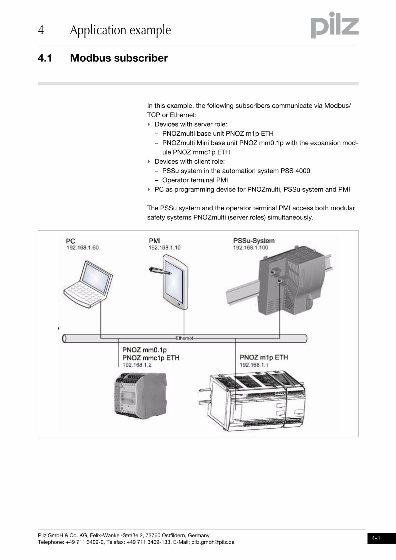
In this example, the following subscribers communicate via Modbus/
TCP or Ethernet:
Devices with server role:
– PNOZmulti base unit PNOZ m1p ETH
– PNOZmulti Mini base unit PNOZ mm0.1p with the expansion mod-
ule PNOZ mmc1p ETH
Devices with client role:
– PSSu system in the automation system PSS 4000
– Operator terminal PMI
PC as programming device for PNOZmulti, PSSu system and PMI
The PSSu system and the operator terminal PMI access both modular
safety systems PNOZmulti (server roles) simultaneously.
4.2 Data exchange via Modbus/TCP
4 Application example
Pilz GmbH & Co. KG, Felix-Wankel-Straße 2, 73760 Ostfildern, Germany
Telephone: +49 711 3409-0, Telefax: +49 711 3409-133, E-Mail: [email protected]
4.2Data exchange via Modbus/TCP4200Data exchange via Modbus/TCP4-ModbusTCP_Bsp_Kommunikation Client - Server
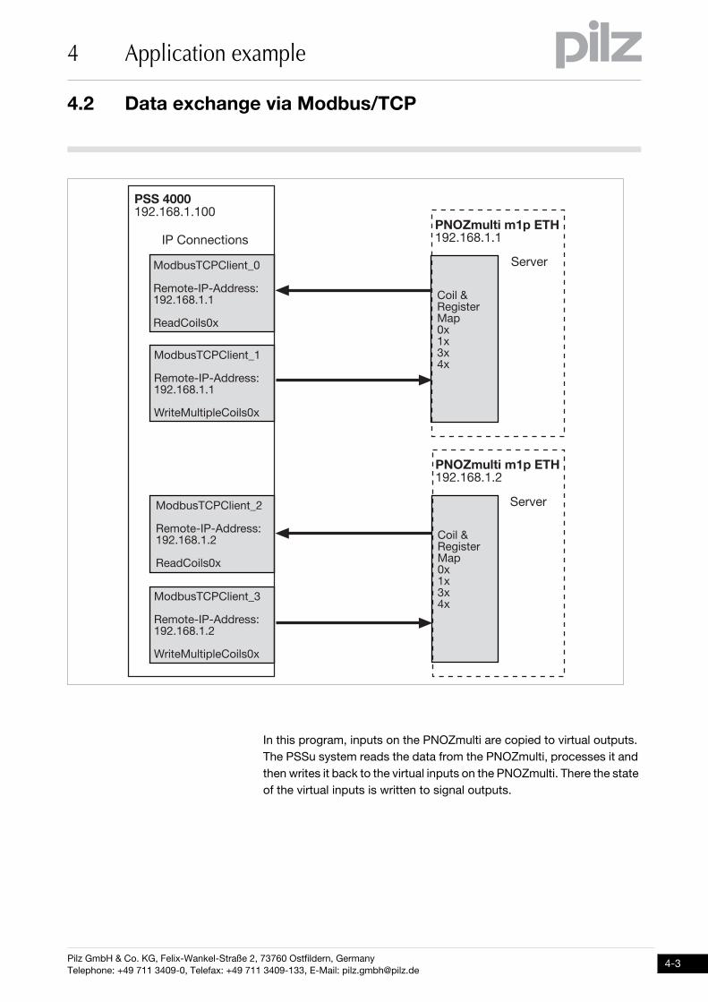
An example of data exchange is shown below. The modular safety sys-
tem PNOZmulti is always the server in a connection and the PSSu sys-
tem from the automation system PSS 4000 is always the client in a
connection.
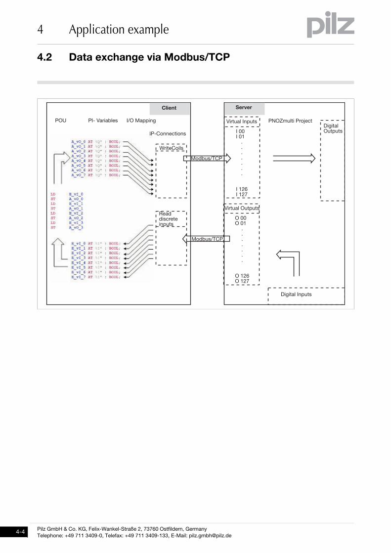
It is always the connection's client that initiates data transfer. The direc-
tion of the data flow (send/receive) and access to Modbus/TCP data ar-
eas (coils, discrete inputs, input registers, holding register) is defined by
the function code.
When sending, the connection's client sends data to a data area belong-
ing to the connection's server. This is also known as "Writing data".
When receiving, the connection's client requests and receives data lo-
cated in a data area belonging to the connection's server. This is also
known as "Reading data".
Pilz GmbH & Co. KG, Felix-Wankel-Straße 2, 73760 Ostfildern, Germany
Telephone: +49 711 3409-0, Telefax: +49 711 3409-133, E-Mail: [email protected]
4.2 Data exchange via Modbus/TCP
4 Application example
In this program, inputs on the PNOZmulti are copied to virtual outputs.
The PSSu system reads the data from the PNOZmulti, processes it and
then writes it back to the virtual inputs on the PNOZmulti. There the state
of the virtual inputs is written to signal outputs.
���������������������
�� ������ ��
� ��������������
��� ����������� �����������
��!�� ����"
� ��������������
��� ����������� �����������
#���������$��� ����"
� �������������%
��� ����������� �����������
#���������$��� ����"
� ��������������
��� ����������� �����������
��!�� ����"
����� �������������������
� ���&��'������!$�"�"%"("
����� �������������������
� ���&��'������!$�"�"%"("
)��*��
)��*��
4.2 Data exchange via Modbus/TCP
4 Application example
Pilz GmbH & Co. KG, Felix-Wankel-Straße 2, 73760 Ostfildern, Germany
Telephone: +49 711 3409-0, Telefax: +49 711 3409-133, E-Mail: [email protected]
����� ������
��!�����������$���
�� ������ ��
+,�����������������-!��!����������.+��!$$��'
#����� ���
-����!���$���
������
�������
�������/
-����!��+��$���
+���+���
�������
+����+���/
0+1������� 2���3�'��!�+��$���
3�'��!���$���
� ����.��
� ����.��
Pilz GmbH & Co. KG, Felix-Wankel-Straße 2, 73760 Ostfildern, Germany
Telephone: +49 711 3409-0, Telefax: +49 711 3409-133, E-Mail: [email protected]
4.3 Device configuration
4 Application example
4.3Device configuration4300Device configuration4-
4.3.1 Modular safety system PNOZmulti Modular safety system PNOZmulti 4-ModbusTCP_Bsp_Konfiguration-PNOZmulti
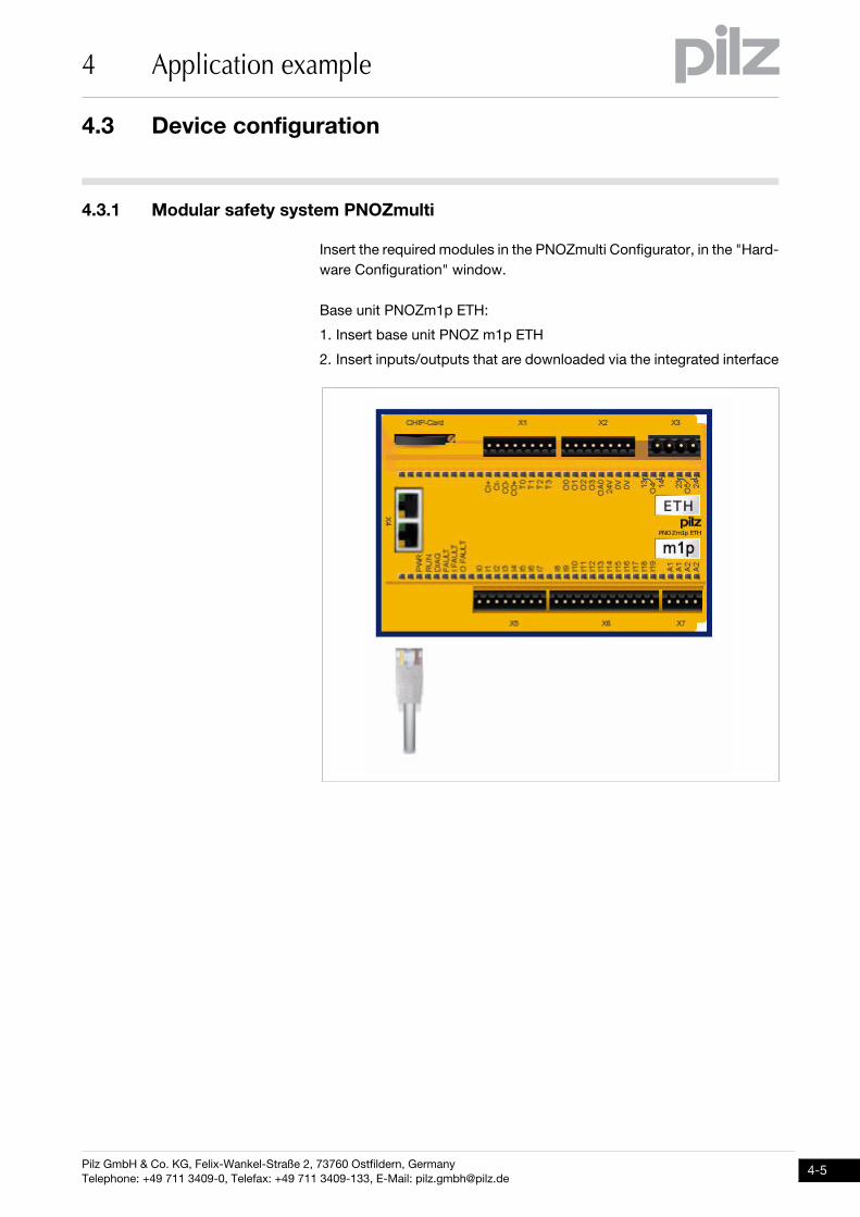
Insert the required modules in the PNOZmulti Configurator, in the "Hard-
ware Configuration" window.
Base unit PNOZm1p ETH:
1. Insert base unit PNOZ m1p ETH
2. Insert inputs/outputs that are downloaded via the integrated interface
4.3 Device configuration
4 Application example
Pilz GmbH & Co. KG, Felix-Wankel-Straße 2, 73760 Ostfildern, Germany
Telephone: +49 711 3409-0, Telefax: +49 711 3409-133, E-Mail: [email protected]
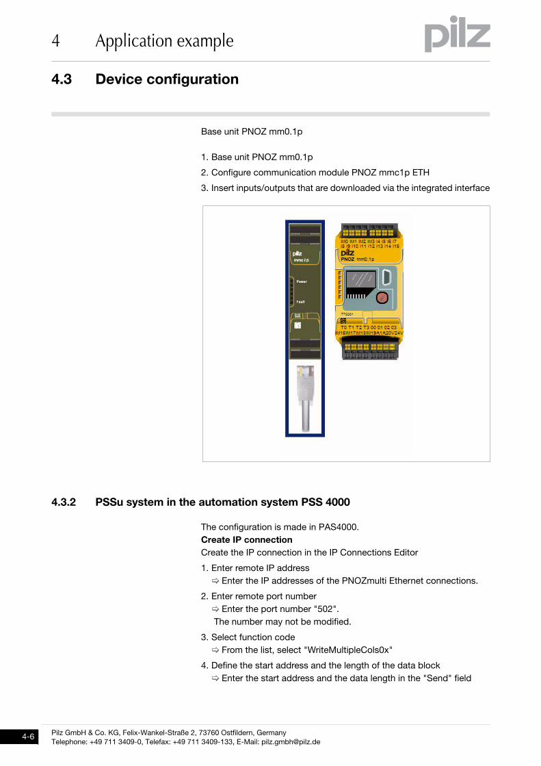
Base unit PNOZ mm0.1p
1. Base unit PNOZ mm0.1p
2. Configure communication module PNOZ mmc1p ETH
3. Insert inputs/outputs that are downloaded via the integrated interface
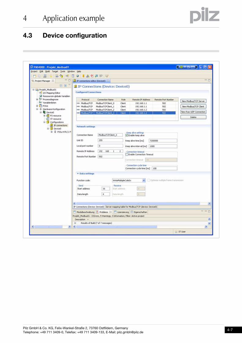
4.3.2 PSSu system in the automation system PSS 4000PSSu system in the automation system PSS 40004-ModbusTCP_Bsp_Konfiguration-PSS 4000
The configuration is made in PAS4000.
Create IP connection
Create the IP connection in the IP Connections Editor
1. Enter remote IP address
Enter the IP addresses of the PNOZmulti Ethernet connections.
2. Enter remote port number
Enter the port number "502".
The number may not be modified.
3. Select function code
From the list, select "WriteMultipleCols0x"
4. Define the start address and the length of the data block
Enter the start address and the data length in the "Send" field
Pilz GmbH & Co. KG, Felix-Wankel-Straße 2, 73760 Ostfildern, Germany
Telephone: +49 711 3409-0, Telefax: +49 711 3409-133, E-Mail: [email protected]
4.3 Device configuration
4 Application example
4.3 Device configuration
4 Application example
Pilz GmbH & Co. KG, Felix-Wankel-Straße 2, 73760 Ostfildern, Germany
Telephone: +49 711 3409-0, Telefax: +49 711 3409-133, E-Mail: [email protected]
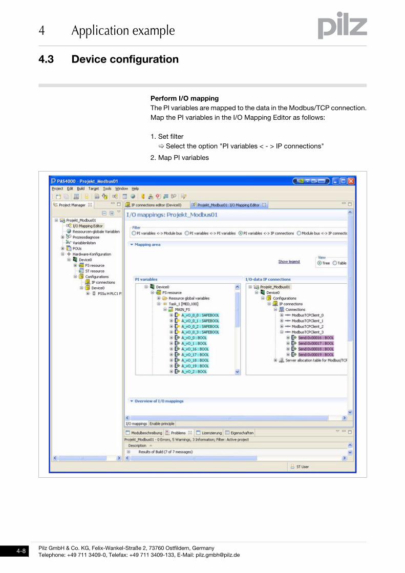
Perform I/O mapping
The PI variables are mapped to the data in the Modbus/TCP connection.
Map the PI variables in the I/O Mapping Editor as follows:
1. Set filter
Select the option "PI variables < - > IP connections"
2. Map PI variables
Pilz GmbH & Co. KG, Felix-Wankel-Straße 2, 73760 Ostfildern, Germany
Telephone: +49 711 3409-0, Telefax: +49 711 3409-133, E-Mail: [email protected]
4.3 Device configuration
4 Application example
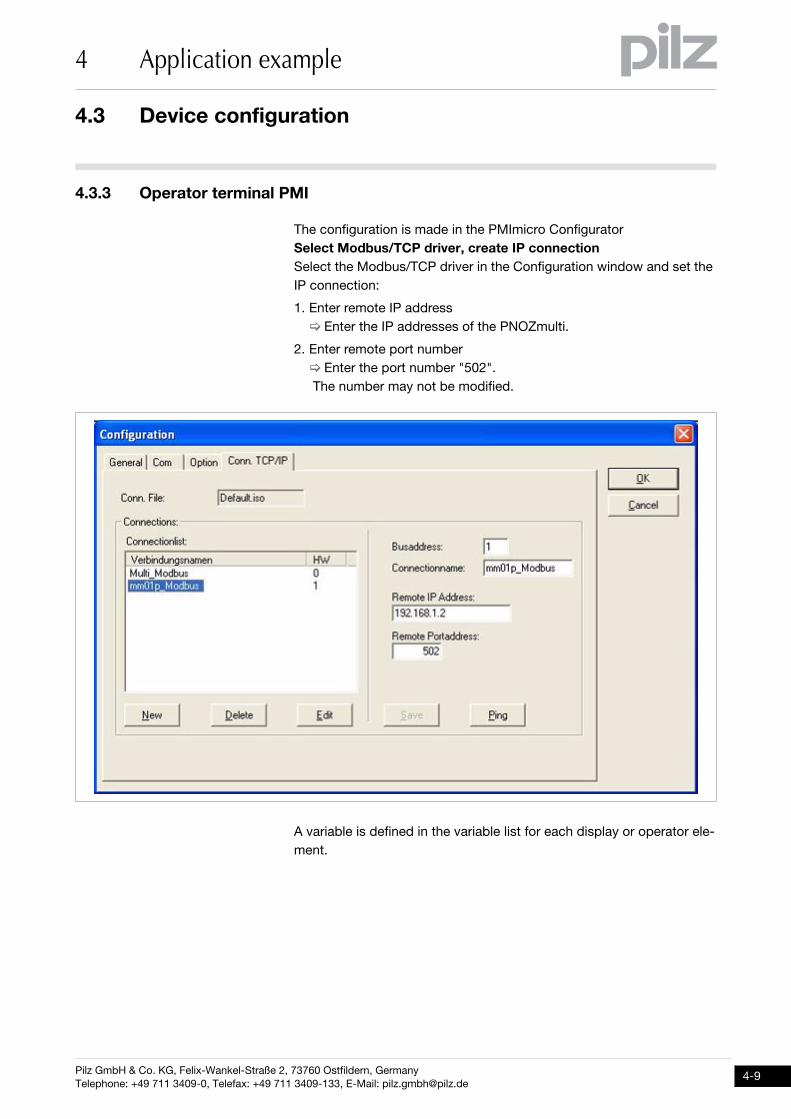
4.3.3 Operator terminal PMIOperator terminal PMI4-ModbusTCP_Bsp_Konfiguration-PMI
The configuration is made in the PMImicro Configurator
Select Modbus/TCP driver, create IP connection
Select the Modbus/TCP driver in the Configuration window and set the
IP connection:
1. Enter remote IP address
Enter the IP addresses of the PNOZmulti.
2. Enter remote port number
Enter the port number "502".
The number may not be modified.
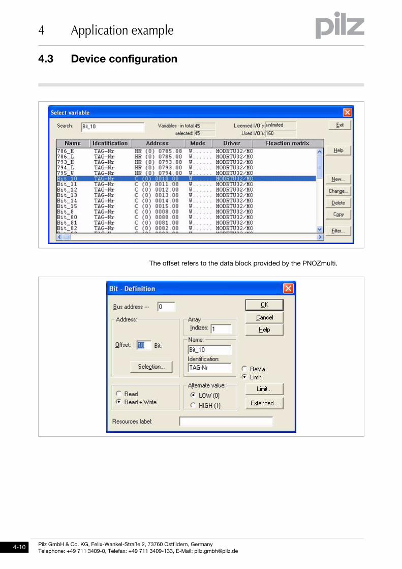
A variable is defined in the variable list for each display or operator ele-
ment.
4.3 Device configuration
4 Application example
Pilz GmbH & Co. KG, Felix-Wankel-Straße 2, 73760 Ostfildern, Germany
Telephone: +49 711 3409-0, Telefax: +49 711 3409-133, E-Mail: [email protected]
The offset refers to the data block provided by the PNOZmulti.
... ww
w
1002104-EN-01, 2010-09 Printed in Germany
© Pilz GmbH & Co. KG, 2010
ww
w.p
ilz.c
om
+49 7
11 3
409-4
44
sup
po
rt@p
ilz.c
om
Pilz
Gm
bH
& C
o. K
GF
elix
-Wankel-S
traße 2
73760 O
stfild
ern
, Germ
any
Tele
pho
ne: +
49 7
11 3
409-0
Tele
fax:
+49 7
11 3
409-1
33
E-M
ail:
p
ilz.g
mb
h@
pilz
.de
Tech
nica
l sup
po
rt
In m
any c
ountrie
s w
e a
re
rep
resente
d b
y o
ur s
ub
sid
iarie
s
and
sale
s p
artn
ers
.
Ple
ase re
fer to
our h
om
ep
ag
e
for fu
rther d
eta
ils o
r co
nta
ct o
ur
head
quarte
rs.
InduraNET p®, Pilz®, PIT®, PMCprotego®, PMI®, PNOZ®, Primo®, PSEN®, PSS®, PVIS®, SafetyBUS p®, SafetyEYE®, SafetyNET p®, the spirit of safety® are registered and protected trademarks
of Pilz GmbH & Co. KG in some countries. We would point out that product features may vary from the details stated in this document, depending on the status at the time of publication and the scope
of the equipment. We accept no responsibility for the validity, accuracy and entirety of the text and graphics presented in this information. Please contact our Technical Support if you have any questions.


