36
POCKET GUIDE AIR TOOLS INSTALLATION 1 POCKET GUIDE AIR TOOLS INSTALLATION

P O C K E T G U I D E A I R T O O L S I N S TA L L AT I O N 11
POCKET GUIDEAIR TOOLS INSTALLATION

22 P O C K E T G U I D E A I R T O O L S I N S TA L L AT I O N
INTRODUCTION
Air tools and compressed air systems are used throughout
industry. This booklet has been produced by Atlas Copco as
an aid to understanding the operation of compressed air
systems, to provide the basic information for the correct
design of these systems and to illustrate the drawbacks and
additional costs incurred with a poorly designed system.
22 P O C K E T G U I D E A I R T O O L S I N S TA L L AT I O N

3P O C K E T G U I D E A I R T O O L S I N S TA L L AT I O N 3
CONTENTS1. The importance of a correct air infrastructure 4
1.1 Practical examples when grinding, drilling, assembling with nutrunners, impact wrenches and pulse tools 4
2. Use the correct air pressure 82.1 What pressure drop is acceptable? 82.2 How to improve the air line 92.3 Key questions 10
3. Air tool installations 123.1 Assembly tools 123.2 Material removal tools 13
4. How do you build your air line? 14 5. Air line infrastructure for tools 14
5.1 Air preparation units 145.2 Air filters 155.3 Air pressure regulators 165.4 Lubricators 165.5 Hoses 175.6 Whip hoses 185.7 Spiral hoses 185.8 Hose reel balancers 185.9 Blow protectors 195.10 Swivels 195.11 Couplings and nipples 195.12 Safety nipples 205.13 Hose clamps 20
6. Recomended air installation by Atlas Copco 21 7. Maintenance 23
7.1 Leakage 237.2 Maintenance schedule 23
8. Safety 249. What is compressed air? 26
9.1 Gravity at sea level 269.2 Difference between gas and liquid 279.3 Relationship between tool pressure and air consumption 289.4 Pressure drop 299.5 Definitions 29
10. Air distrubution 30 10.1 The system 3010.2 Ring main and offtakes 3110.3 The service line 31 10.4 Air users 3110.5 Compressed air treatment 3210.6 Removing the water from compressed air 32 10.7 Adsorption drying 33 10.8 Other methods 33 10.9 The need for water traps andfilters 33 10.10 Cost of pipework 33
44 P O C K E T G U I D E A I R T O O L S I N S TA L L AT I O N
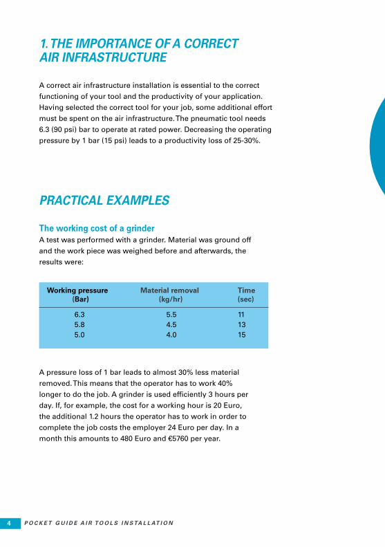
Working pressure Material removal Time (Bar) (kg/hr) (sec)
6.3 5.5 11 5.8 4.5 13 5.0 4.0 15
1. THE IMPORTANCE OF A CORRECT AIR INFRASTRUCTURE
A correct air infrastructure installation is essential to the correct
functioning of your tool and the productivity of your application.
Having selected the correct tool for your job, some additional effort
must be spent on the air infrastructure. The pneumatic tool needs
6.3 (90 psi) bar to operate at rated power. Decreasing the operating
pressure by 1 bar (15 psi) leads to a productivity loss of 25-30%.
PRACTICAL EXAMPLES
The working cost of a grinderA test was performed with a grinder. Material was ground off
and the work piece was weighed before and afterwards, the
results were:
A pressure loss of 1 bar leads to almost 30% less material
removed. This means that the operator has to work 40%
longer to do the job. A grinder is used efficiently 3 hours per
day. If, for example, the cost for a working hour is 20 Euro,
the additional 1.2 hours the operator has to work in order to
complete the job costs the employer 24 Euro per day. In a
month this amounts to 480 Euro and €5760 per year.

5P O C K E T G U I D E A I R T O O L S I N S TA L L AT I O N 5
A pressure loss of 1 bar can cost your company €5760 per year!
5P O C K E T G U I D E A I R T O O L S I N S TA L L AT I O N 5

66 P O C K E T G U I D E A I R T O O L S I N S TA L L AT I O N
When drilling with lower air pressures,
there is a risk of adding up to 1.2 extra
seconds per hole. That is 60% longer
time. If the efficient drilling time per
day is 1 hour, the 36
minutes extra time
is required per day
to complete the
same job. That
results in a total
of €12 extra per
day (at a cost per
hour of €20).
Time to
make a hole
(sec)
2.0
3.2
Working
pressure
(Bar)
6.3
5.8
Drilling
Using a pneumatic screwdriver at a
too low air pressure in this example,
results in a 12.5 % longer assemblying
time. Assume the cost for the operator
is €20/hour and the efficient assem-
bling time is 4 hours/day. This means
that the cost normally is €80/day. 80 x
0.125 = €10/day of unnecessary work.
Time
(sec)
0.8
0.9
Maximum
torque
(Nm)
248
240
Working
pressure
(Bar)
6.3
5.8
Assembling
WHEN YOUR AIR SYSTEM IS FUNCTIONING PROPERLY, YOU
SAVE UP TO €2880 PER YEAR!
PRACTICAL EXAMPLES

7P O C K E T G U I D E A I R T O O L S I N S TA L L AT I O N 7
Pulse tools Tests performed at Atlas Copco show
that decreased working pressure sig-
nificantly increases tightening time and
reduces the torque obtained. Tests were
made with an ErgoPulse 8 XS.
Impact wrenchesThe torque increases with time on
impact wrenches. The time to reach
the torque increases with declining
pressure. Tests with the tool show a
12.5% time increase at 0.5 bar lower
air pressure.
At an operator cost of 20 Euro per hour
and 4 hours of efficient assembling,
this gives 10 Euro unnecessary work
every day, (200 Euro per month, 2400
Euro per year).
SAVE UP TO2400 EUROPER YEAR!
Assembling
The tool is at risk of poor performance
when recommended air pressure is not
maintained.
In this pulse tool example, there is a
increase of 50% in cycle time. If the ef-
ficient tightening time is 4 hours/day and
the wage of the operator is €20/hour,
means that €800 /month and €9600/year
can be saved by having the correct work-
ing air pressure.
Time
(sec)
6.5
10
10
Working
pressure (Bar)
6.3
5.3
4.3
Torque
(Nm)
48.3
44.3
38.2
DECREASED WORKING PRESSURE
SIG NIFICANTLY INCREASES
TIGHTENING TIME!
DECREASED WORKING PRESSURE
SIG NIFICANTLY INCREASES
TIGHTENING TIME!
88 P O C K E T G U I D E A I R T O O L S I N S TA L L AT I O N
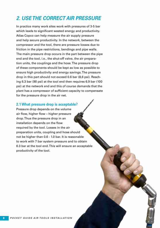
2. USE THE CORRECT AIR PRESSUREIn practice many work sites work with pressures of 3-5 bar
which leads to significant wasted energy and productivity.
Atlas Copco can help measure the air supply pressure
and help secure productivity. In the network, between the
compressor and the tool, there are pressure losses due to
friction in the pipe restrictions, bendings and pipe walls.
The main pressure drop occurs in the part between the pipe
end and the tool, i.e., the shut-off valve, the air prepara-
tion units, the couplings and the hose. The pressure drop
of these components should be kept as low as possible to
ensure high productivity and energy savings. The pressure
drop in this part should not exceed 0.6 bar (8,6 psi). Reach-
ing 6.3 bar (90 psi) at the tool end then requires 6.9 bar (100
psi) at the network end and this of course demands that the
plant has a compressor of sufficient capacity to compensate
for the pressure drop in the air net.
2.1 What pressure drop is acceptable?Pressure drop depends on the volume
air flow, higher flow – higher pressure
drop. Thus the pressure drop in an
installation depends on the flow
required by the tool. Losses in the air
preparation units, coupling and hose should
not be higher than 0.6 - 1.0 bar. It is reasonable
to work with 7 bar system pressure and to obtain
6.3 bar at the tool end. This will ensure an acceptable
productivity of the tool.

9P O C K E T G U I D E A I R T O O L S I N S TA L L AT I O N 9
2.2 How to improve the air lineThe capacities of Atlas Copco air line products and accessories
have been measured and the flow is stated with the corresponding
pressure drop. This makes it possible for the user to choose the
correct accessories for the application and to achieve an acceptable
pressure drop.
Restrictions such as small size couplings, too long and small
diameter hoses create pressure losses. Spiral hoses are, due to
their shape, very long and thus they create a large pressure drop.
The alternative, a normal PVC hose should in every case be consid-
ered with regards to the pressure losses. Every coupling in an in-
stallation creates a pressure loss. For example a whip hose makes
it easier to work with the tool but the extra coupling and small bore
hose can create a pressure drop of 0.2-0.5 bar depending on size
and air consumption.

1010 P O C K E T G U I D E A I R T O O L S I N S TA L L AT I O N
Does the tool need lubrication?Air tool manufacturers make tools
with special vanes not needing
lubri cation. Turbines do not need
lubrication either. Some tools do
need lubrication and those with
short operating times require direct
lubrication, long operating times
require an oil-fog lubricator.
Distance between the tool and the offtake?The distance between the tool
and the offtake should ideally not
be more than 3-5 meters. Real life
shows that in many cases this
is not possible, for instance at
shipyards, where distances of 20
meters or more are quite common.
Inlet thread dimension of the tool? The connection between the hoses
and the tools vary in size, from 1/8”
up to 1/2”. The correct nipple must to be
chosen for each tool.
Air consumption?The size of accessories is
determined by the air consump-
tion of the tool. Larger air con-
sumption results in larger size
accessories.
Working environment?The choice of accessories is influ-
enced by the working environment.
Outdoor use or rough environ-
ments like foundries require more
resistant air line accessories than
indoor benchwork assembling light
machinery.
Allowable pressure drop? The tool requires sufficient pres-
sure to function properly. The sys-
tem pressure can be set high if the
system pressure drop is large but
in any case, the maximum allowa-
blepressure drop of the accesso-
ries must be determined and they
should be chosen accordingly.
2.3 KEY QUESTIONSWhen the tool of the correct size and power for the application has been selected,
the air line of the right size must be chosen. The parameters for choosing are:
1010 P O C K E T G U I D E A I R T O O L S I N S TA L L AT I O N
11P O C K E T G U I D E A I R T O O L S I N S TA L L AT I O N 1111P O C K E T G U I D E A I R T O O L S I N S TA L L AT I O N 11

1212 P O C K E T G U I D E A I R T O O L S I N S TA L L AT I O N
3. AIR TOOL INSTALLATIONS
3.1 Assembly toolsSmall couplings are suitable for
assembly tools which require low
air flow rates. Large impact wrenches
require larger size couplings. The hose
sizes for an assembly tool can in most cases
be between 6 to 13 mm and the length is
usually 3-5 m. In some few cases the hoses
are larger and longer.
An installation with a straight plastic hose
and couplings is the most common, when
working with pistol grip assembly tools
with low levels of vibrations.
Hose reel balancers is used for straight
screwdrivers, the need for couplings
depends on if the operator needs to
change tool or not.
Main hoses together with a short whip
hose is recommended where there are hard
impacts on the couplings (impact wrenches)
or when the tools are very heavy and the
weight of the tools can break the couplings.
Spiral hoses can be used with a straight screw-
driver together with a balancer. Another way is to
use a larger spiral hose with pistol grip tools.
The need of couplings is dependent on whether
or not the operator needs to change tool.

13P O C K E T G U I D E A I R T O O L S I N S TA L L AT I O N 13
3.2 Material removal toolsCouplings of larger size must be used as air consumption is
higher than on assembly tools, smaller couplings are used for
smaller grinders such as LSF die grinders. The hose sizes for
a material removal tool can in most cases be between 10 to
20 mm and the length is usually 5 - 10 m. In some few cases
the hoses are larger and longer. This installation is common
when working with material removal tools with low levels of
vibrations.
A main hose together with a short whip hose is recommended
where there are hard impacts on the couplings (percussive
tools and some grinders) or when the tools are very heavy and
the weight of the tools can break the couplings. An extra hose
can be used where there is long distance to cover. Remember
to keep the dimensions large on the extra hose.
13P O C K E T G U I D E A I R T O O L S I N S TA L L AT I O N 13

1414 P O C K E T G U I D E A I R T O O L S I N S TA L L AT I O N
4. HOW DO YOU BUILD YOUR AIR LINE?
A good air compressor and air line will in-
crease the tool and operator productivity. A
high air pressure is not always the best, the
correct air pressure will be most beneficial
in the long run.
Usually the operator wants to maximize the
productivity and raise the air pressure of
the tool. But this is not the best solution in
the long run, in terms of lifetime of the tool
and ergonomic aspects. The best tool per-
formance is reached at 6.3 Bar (90 psi).
Optimizing the air line will both save
money and raise productivity, and below
are the components that we recommend
you to use in a really good air line.
5. AIR LINE INFRASTRUCTURE
5.1 Air preparation unitsIn the range of air preperation units,
Atlas Copco offersthe Midi Optimizer, it is
suitable for most assembly tools, percus-
sive tools, drills, nibblers, saws, and small
grinders (in fact, approximately 90% of all
applications).
Highest recommended air flow:
MINI up to 12 l/sMIDI up to 43 l/sMAXI up to 80 l/s
• Avoid leaks
• Avoid long hoses
• Use correct type of hose
(plastic or rubber) depending
on the application
• Use full flow couplings
• Use clean compressed air
• Use a regulator to set and
monitor the air pressure
(with lubrication also if
needed)
Quick rules/tips:

15P O C K E T G U I D E A I R T O O L S I N S TA L L AT I O N 15
5.2 Air filtersThe filter separates impurities such as water and solid
particles. Not using filters in combination with air tools
leads to shorter service life, higher maintenance costs
and a lower efficiency. Old air systems with cool dryers
generate a lot of rust. Running tools without installing
a filter could damage the tool in less than a week. Well
maintained air systems supply clean air. Although the
difference might not be obvious, the tiniest rust flake
can damage a tool. Intermediate air quality will result
in shorter service intervals with higher costs.
Atlas Copco filters separate up to 98% of the water
when operating within the design working range.
Filters are usually equipped with a semiautomatic
drain. All filters come with a kit enabling simple
conversion from semiautomatic to manual drainage.
Semi-automatic drainage takes place automatically
when the pressure in the bowl drops below 0.2 bar
(requiring the air supply to be switched off regularly).
With automatic drainage the bowl is emptied when
theaccumulated water reaches a certain level.
A metal bowl guard is used when there is a possibility
that there are solvents in the environment. Solvents
which make the polycarbonate bowl brittle are chemi-
cals containing acetone, benzene, glycerine, some
hydraulic and some synthetic oils, chloroform, methyl
alcohol, carbon tetrachloride and similar solvents,
carbon disulphide, perchlorethylene, toluene, trichloret-
hylene, xylene (nitrocellulose thinner) and acetic acid.
If the standard bowl breaks, a metal bowl should be
used. Metal bowl guards are standard in some markets.

1616 P O C K E T G U I D E A I R T O O L S I N S TA L L AT I O N
5.3 Air pressure regulatorsThe air pressure regulator ensures that the
pre-set working pressure remains constant
– regardless of pressure variations in the
intake air and minor variations in the air
flow rate. By preventing unnecessary con-
sumption of air, the air pressure regulator
improves overall operating economy.
5.4 LubricatorsIf lubricators are not used the vanes have to be changed
more often. The life of the vanes may decrease to as little as
1/10th of the normal working time. Tests in Atlas Copco labo-
ratories showed that the power output of a grinder decreases
by 15-20% after 20 minutes when not lubricated.
The most common type of lubricator, the oil fog lubricator,
supplies drops of oil to the air hose. It is used to lubricate air
tools which have a normal operation time and is the standard
method of lubricating air tools. Metal bowls should be used
when there is an aggressive environment, (see filters). A
glass sight dome can be used with units with a metal bowl.
For air tools that are started and stopped at short intervals
or have a very low air consumption, an one point lubricator
should be used. This supplies oil in drops through a capil-
lary tube in the hose directly to the tool and is controlled by
the tool starting frequency. Many assembly tools, but not
those with lube free vanes, can be used in combination with
Tool pressure (bar)
6.37.08.0
Air consumption(%)
100110125
Piston regulators use the air to regulate and therefore react
more slowly. On the other hand, they have improved regu-
lating characte istics, such as maintained outlet pressure
over a wide range of air flows. Piston regulators should be
used in air flow operations where precision is essential and
slow response can be accepted, typically for air motors.
Spring controlled regulators are quick acting and therefore
should be used for all types of air tools. This type of regula-
tor isalso the most common.

17P O C K E T G U I D E A I R T O O L S I N S TA L L AT I O N 17
a direct lubricator. When using long hoses it is easy to get a
dip (i.e. a hose loop forming a low point where the oil is col-
lected). In this case it is better to have, if possible, a portable
oil fog lubricator or manually drop some oil drops into the air
tool inlet every hour.
F/R units are combined filter / regulators assembled together.
F/R units are recommendedin every case where both filters
and regulators are needed. Filtering and regulating and lubri-
cating properties are almost the same as for individual units.
5.5 HosesHoses should be chosen to meet the demands of the working
environment. The hoses should have a length
of 3-5 m (10-30 ft) to ensure sufficient mobility at the work-
place and limited pressure drop. For light air tools, CABLAIR,
a soft light-weight PVC hose is recommended. It is 30-50%
lighter than conventional PVC hose, and should be used for
clean bench operations.
PVC hoses are suitable for general applications,
from simple grinding to heavy assembly. Rougher
applications require rubber hoses of which Atlas Copco
supplies two types, RUBAIR and TURBO.
TURBO is lighter and very strong while
RUBAIR is even more resistant to a rough
environment and can be supplied in a
larger range of dimensions. To avoid too
large a pressure drop, the hose size should be increased
by one size for a length of 5-10 m (32-50 ft), two sizes for a
length of 20 m (65 ft), and three sizes for lengths of 20-40 m
(65-130 ft).
General rules are to keep hose diameters large, to use high
flow rate couplings, to use air preparation units with low
pressure drop. All these measures make the overall pressure
drop in the installation low and thus productivity is increased
and energy saved.

1818 P O C K E T G U I D E A I R T O O L S I N S TA L L AT I O N
5.6 Whip hosesPercussive tools and impact wrenches tend to destroy the
coupling if it is directly connected to the tool (due to the per-
cussive action and impacts). Also, if the tool
weighs more than 3 kg (large grinders or nut runners) the
coupling can break if the tool is dropped and hits the cou-
pling. A short whip hose is therefore recommended
for these types of tools. It is important to note that air flow
decreases if you split the hose in two. If for instance a 13
mm, 5 m long hose which has a capacity of 21 l/s, were to
be split into whiphose + hose, the capacity would decrease
to 16 l/s (to ≈ 80%). A typical length for whip hoses is 0.3-0.7
meters.
5.7 Spiral hosesA spiral hose together with
balancers is ideal for vertical
applications. Spiral hoses
are, due to their shape,
very long and thus have
very high pressure drop.
To avoid big losses, choose
a short spiral hose.
5.8 Hose reel balancersIn some applications, (preferably vertical), a hose
is suitable in combination with a balancer. A typical
application is a straight screwdriver. In this case a
hose reel balancer is used. The air line is connected to
the balancer block and led through the wound hose which
can be pulled out to a suitable length. Hose reel balancers
are chosen according to the required air flow and the weight
of the tool.
19P O C K E T G U I D E A I R T O O L S I N S TA L L AT I O N 19
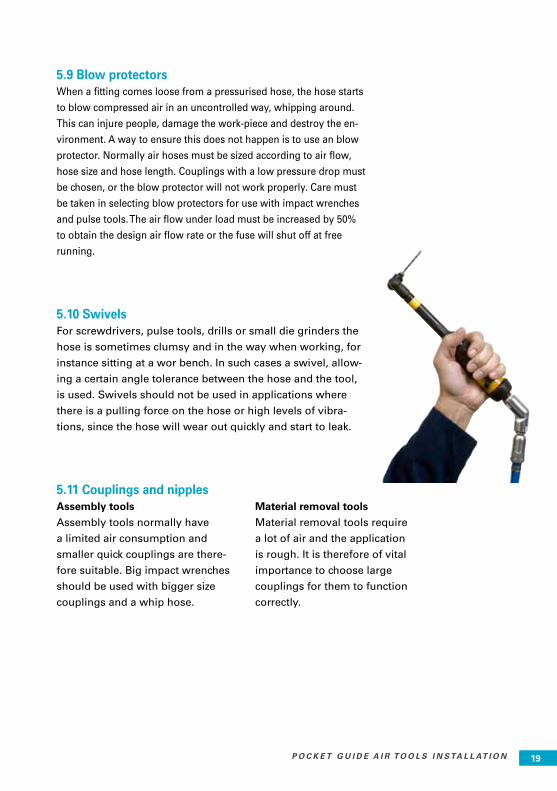
5.9 Blow protectors When a fitting comes loose from a pressurised hose, the hose starts
to blow compressed air in an uncontrolled way, whipping around.
This can injure people, damage the work-piece and destroy the en-
vironment. A way to ensure this does not happen is to use an blow
protector. Normally air hoses must be sized according to air flow,
hose size and hose length. Couplings with a low pressure drop must
be chosen, or the blow protector will not work properly. Care must
be taken in selecting blow protectors for use with impact wrenches
and pulse tools. The air flow under load must be increased by 50%
to obtain the design air flow rate or the fuse will shut off at free
running.
5.10 SwivelsFor screwdrivers, pulse tools, drills or small die grinders the
hose is sometimes clumsy and in the way when working, for
instance sitting at a wor bench. In such cases a swivel, allow-
ing a certain angle tolerance between the hose and the tool,
is used. Swivels should not be used in applications where
there is a pulling force on the hose or high levels of vibra-
tions, since the hose will wear out quickly and start to leak.
5.11 Couplings and nipplesAssembly tools
Assembly tools normally have
a limited air consumption and
smaller quick couplings are there-
fore suitable. Big impact wrenches
should be used with bigger size
couplings and a whip hose.
Material removal tools
Material removal tools require
a lot of air and the application
is rough. It is therefore of vital
importance to choose large
couplings for them to function
correctly.
2020 P O C K E T G U I D E A I R T O O L S I N S TA L L AT I O N
5.12 Safety nipplesWhen the hose is longer than 3 meters, the pressurised air
left in the hose could create such a bang when the hose is
disconnected, that a safety nipple should be used. The safety
nipple lets the air out very slowly when the hose is discon-
nected. When using safety nipples, the air flow is reduced
by 20%. When for instance a 16 mm, 5 m hose is used with
safety nipple and a whip hose the following will happen: The
normal maximum air flow rate of 43 l/s is reduced to 80%
because of the safety nipple => 35 l/s, and further reduced by
20% due to the whip hose => 28 l/s.
5.13 Hose clampsHose clamps are available in three types: pleated type for
hoses with outside diameters of 7-27 mm, screw-strip types
for hoses with outside diameters of 8-65 mm; and two-part
cast iron clamps with a galvanised bolt and nut for hoses
with outside diameters of 22-40 mm. Single lugged, medium
pressure clamps re recommended for use with small PVC
hoses. Medium pressure clamps (worm drive) are recom-
mended for PVC hoses and smaller rubber hoses up to 16
mm diameter. For rubber hoses above 16 mm, heavy duty
clamps should be used.
21P O C K E T G U I D E A I R T O O L S I N S TA L L AT I O N 21
6. RECOMENDED AIR INSTALLATION BY ATLAS COPCO
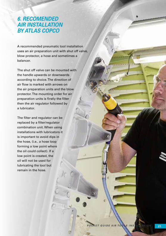
A recommended pneumatic tool installation
uses an air preparation unit with shut off valve,
blow protector, a hose and sometimes a
balancer.
The shut off valve can be mounted with
the handle upwards or downwards
according to choice. The direction of
air flow is marked with arrows on
the air preparation units and the blow
protector. The mounting order for air
preparation units is firstly the filter
then the air regulator followed by
a lubricator.
The filter and regulator can be
replaced by a filter/regulator
combination unit. When using
installations with lubricators it
is important to avoid dips in
the hose, (i.e.. a hose loop
forming a low point where
the oil could collect). If a
low point is created, the
oil will not be used for
lubricating the tool but
remain in the hose.
21P O C K E T G U I D E A I R T O O L S I N S TA L L AT I O N 21

2222 P O C K E T G U I D E A I R T O O L S I N S TA L L AT I O N2222 P O C K E T G U I D E A I R T O O L S I N S TA L L AT I O N

23P O C K E T G U I D E A I R T O O L S I N S TA L L AT I O N 23
7. MAINTENANCE
7.1 LeakageA well-designed and properly maintained air distri-bution system has a leakage of no
more than 5% of the capacity of the installation. Unfortunately, 15-20% leakage is quite
common. Leakage translates into a loss of air capacity. This means increased utilisation
of the compressor as it works to compensate, which in turn leads to significantly higher
energy costs.
* 1kWh = 0.035 Euro ** Calculation based on 24 h/day. For example, a hole with a diameter of 5 mm results in a leakage of 27 litres of air per second from the air distribution system. To compensate for this loss of air flow capacity, 8.3 kW of additional compressor power is required. With an average price per kWh of 0.035 Euro, this relatively small hole results in an additional, annual energy cost of 2510 Euro.
Leakage rates and equivalent hole diameters
Hole
diameter
mm
1
3
5
10
Air leakage
at 6.3 bar
L/s
1
10
27
105
Additional
compressor
power req.
0.3
3.1
8.3
33.0
Typical energy
kW cost
per year *
91 Euro
937 Euro
2510 Euro
9979 Euro
ONCE EVERY DAY: Drain applicable filters.
ONCE PER WEEK: The area closest to the workplace should be checked for leakage once per week. Joints between tools and nip-ples, in couplings, hoses and air preparation units should be checked. Lubricators should be filled with oil.
EVERY TWO MONTHS: The whole air system should be checked every two months. First, listen for leaks after working hours, feel by hand on suspected areas. A soap and water solution can be used to detect the exact point of leakage, (bubbles). Take the necessary measures to repair the leak. Every workplace should be checked with the air tool simulator every two months. The air tool simulator should be connected to the hose and the required air flow (given in a table enclosed with the air tool simulator) should be set by a certain number of revolutions of the knob. The pressure has to be 6.3 bar (90 psi) at the hose end for the tool to function properly.
Take the necessary measures by changing FRL, hose and/or coupling.
EVERY SIX MONTHS: Filter elements should be cleaned with a blowgun every 6 months. This is to avoid increased pres-sure drop.
The relief valve of the blow protector should be blown clean every 6 months. This is to avoid disturbances of the automatic resetting of the blow protector.
Atlas Copco offers to provide a maintenance schedule for a site and, if required, to imple-ment it.
AIR LEAKAGE IS OFTEN
CONTINUOUS, 24 HOURS
A DAY!
7.2 Maintenance scheduleRegular maintenance should be carried out on the air system.
2424 P O C K E T G U I D E A I R T O O L S I N S TA L L AT I O N
8. SAFETYBall valves: When not working, shut off the compressed
air with the ball valve. Open all ball valves slowly in order
to discover improperly tightened devices.
Air preparation units: Be aware of solvents which can change
the structure of polycarbonate bowls making them brittle.
When using aggressive solvents special equipment is re-
quired. Polycarbonate has good chemical resistance to all
solvents except chemicals containing acetone, benzene, glyc-
erine, some hydraulic and synthetic oils, chloroform, methyl
alcohol, carbon tetrachloride (and similar solvents) carbon
disulphide, perchloroethylene, toluene, trichlorethylene, xy-
lene (nitrocell lose thinner) and acetic acid. It is important to
check that the bowls are properly tightened and all units are
assembled together before turning on the compressed air
with the ball valve.
Quick couplings: Quick couplings are normally very safe
devices. Extra care, however, should be taken when working
with hose diameters larger than 16 mm or hose lengths long-
er than 3 m. In these cases a safety nipple which vents the air
from the hose in a controlled way is recommended.
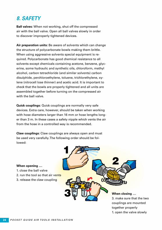
Claw couplings: Claw couplings are always open and must
be used very carefully. The following order should be fol-
lowed:
When opening ....
1. close the ball valve
2. run the tool so that air vents
3. release the claw coupling
When closing ....
3. make sure that the two
couplings are mounted
together properly
1. open the valve slowly
25P O C K E T G U I D E A I R T O O L S I N S TA L L AT I O N 25
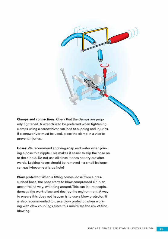
Clamps and connections: Check that the clamps are prop-
erly tightened. A wrench is to be preferred when tightening
clamps using a screwdriver can lead to slipping and injuries.
If a screwdriver must be used, place the clamp in a vice to
prevent injuries.
Hoses: We recommend applying soap and water when join-
ing a hose to a nipple. This makes it easier to slip the hose on
to the nipple. Do not use oil since it does not dry out after-
wards. Leaking hoses should be removed – a small leakage
can easilybecome a large hole!
Blow protector: When a fitting comes loose from a pres-
surised hose, the hose starts to blow compressed air in an
uncontrolled way, whipping around. This can injure people,
damage the work-piece and destroy the environment. A way
to ensure this does not happen is to use a blow protector. It
is also recommended to use a blow protector when work-
ing with claw couplings since this minimizes the risk of free
blowing.

2626 P O C K E T G U I D E A I R T O O L S I N S TA L L AT I O N
9. WHAT IS COMPRESSED AIR?
Air is vital to life on earth and we breathe it all the time.
It is a colourless, odourless and tasteless gas mixture
consisting mostly of nitrogen, oxygen and some water
vapour. Air is always contaminated with solid
particles, such as sand, soot and salt crystals;
its composition is relatively constant
from sea level to an altitude of 25 km.
When air is compressed, it becomes a safe,
versatile medium for transmitting and
storing energy. But what is compressed air?
Quite simply, the atmosphere at work.
9.1 Gravity at sea levelAll material, including small air particles, is
attracted to earth by gravity. The gravitational
force exerted on an object is determined by its
distance from the earth - the further away from
earth, the less the gravitational force.
Imagine an area of one square centimetre at sea level and
travelling away from earth to form a column of air to the edge
of the atmosphere. Imagine gravity pulling the atoms within the
column to earth.
2626 P O C K E T G U I D E A I R T O O L S I N S TA L L AT I O N

27P O C K E T G U I D E A I R T O O L S I N S TA L L AT I O N 27
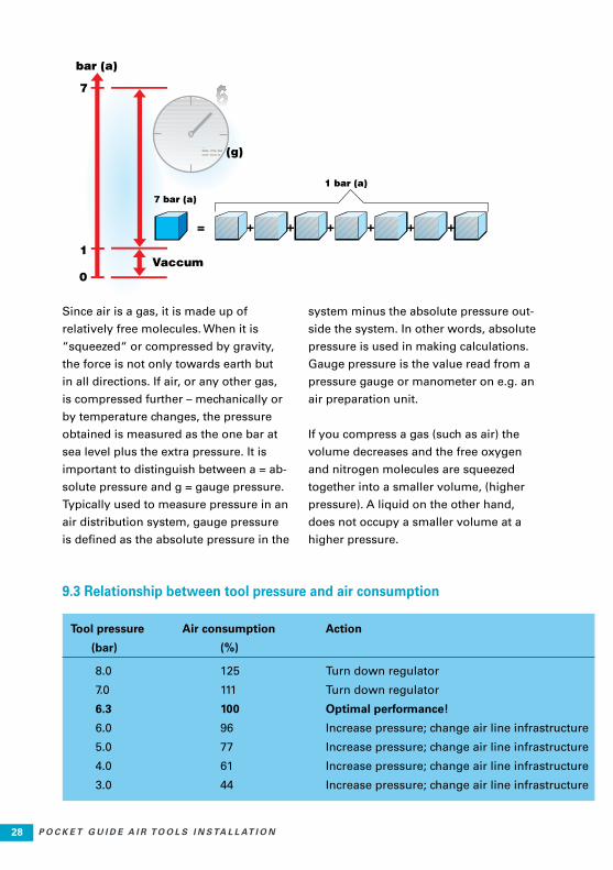
9.2 Difference between gas and liquidMeasured in Newton, the force
exerted on one square centime-
tre at sea level is about 10.13 N.
Therefore the absolute atmos-
pheric pressure at sea level is
approximately 10.13 x 10⁴ N per
square meter, which is also called
1 Pa (Pascal), the SI unit for pres-
sure. The most common unit for
measuring pressure is, however,
the bar. The atmospheric pressure
at sea level is thus 105 Pa or ap-
proximately 1 bar, an air pressure
which is referred to as the abso-
lute pressure.
27P O C K E T G U I D E A I R T O O L S I N S TA L L AT I O N 27
2828 P O C K E T G U I D E A I R T O O L S I N S TA L L AT I O N
Since air is a gas, it is made up of
relatively free molecules. When it is
“squeezed“ or compressed by gravity,
the force is not only towards earth but
in all directions. If air, or any other gas,
is compressed further – mechanically or
by temperature changes, the pressure
obtained is measured as the one bar at
sea level plus the extra pressure. It is
important to distinguish between a = ab-
solute pressure and g = gauge pressure.
Typically used to measure pressure in an
air distribution system, gauge pressure
is defined as the absolute pressure in the
system minus the absolute pressure out-
side the system. In other words, absolute
pressure is used in making calculations.
Gauge pressure is the value read from a
pressure gauge or manometer on e.g. an
air preparation unit.
If you compress a gas (such as air) the
volume decreases and the free oxygen
and nitrogen molecules are squeezed
together into a smaller volume, (higher
pressure). A liquid on the other hand,
does not occupy a smaller volume at a
higher pressure.
=
9.3 Relationship between tool pressure and air consumption
Tool pressure Air consumption Action
(bar) (%)
8.0 125 Turn down regulator
7.0 111 Turn down regulator
6.3 100 Optimal performance!
6.0 96 Increase pressure; change air line infrastructure
5.0 77 Increase pressure; change air line infrastructure
4.0 61 Increase pressure; change air line infrastructure
3.0 44 Increase pressure; change air line infrastructure
29P O C K E T G U I D E A I R T O O L S I N S TA L L AT I O N 29
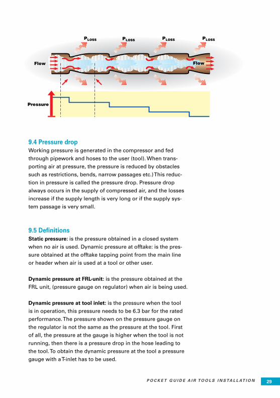
9.4 Pressure dropWorking pressure is generated in the compressor and fed
through pipework and hoses to the user (tool). When trans-
porting air at pressure, the pressure is reduced by obstacles
such as restrictions, bends, narrow passages etc.) This reduc-
tion in pressure is called the pressure drop. Pressure drop
always occurs in the supply of compressed air, and the losses
increase if the supply length is very long or if the supply sys-
tem passage is very small.
9.5 DefinitionsStatic pressure: is the pressure obtained in a closed system
when no air is used. Dynamic pressure at offtake: is the pres-
sure obtained at the offtake tapping point from the main line
or header when air is used at a tool or other user.
Dynamic pressure at FRL-unit: is the pressure obtained at the
FRL unit, (pressure gauge on regulator) when air is being used.
Dynamic pressure at tool inlet: is the pressure when the tool
is in operation, this pressure needs to be 6.3 bar for the rated
performance. The pressure shown on the pressure gauge on
the regulator is not the same as the pressure at the tool. First
of all, the pressure at the gauge is higher when the tool is not
running, then there is a pressure drop in the hose leading to
the tool. To obtain the dynamic pressure at the tool a pressure
gauge with a T-inlet has to be used.
Flow
Pressure
Flow
3030 P O C K E T G U I D E A I R T O O L S I N S TA L L AT I O N
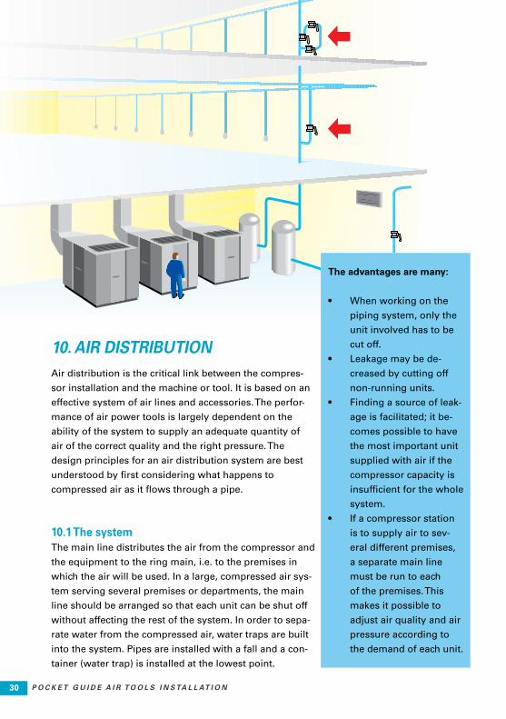
10. AIR DISTRIBUTION Air distribution is the critical link between the compres-
sor installation and the machine or tool. It is based on an
effective system of air lines and accessories. The perfor-
mance of air power tools is largely dependent on the
ability of the system to supply an adequate quantity of
air of the correct quality and the right pressure. The
design principles for an air distribution system are best
understood by first considering what happens to
compressed air as it flows through a pipe.
10.1 The systemThe main line distributes the air from the compressor and
the equipment to the ring main, i.e. to the premises in
which the air will be used. In a large, compressed air sys-
tem serving several premises or departments, the main
line should be arranged so that each unit can be shut off
without affecting the rest of the system. In order to sepa-
rate water from the compressed air, water traps are built
into the system. Pipes are installed with a fall and a con-
tainer (water trap) is installed at the lowest point.
The advantages are many:
• When working on the
piping system, only the
unit involved has to be
cut off.
• Leakage may be de-
creased by cutting off
non-running units.
• Finding a source of leak-
age is facilitated; it be-
comes possible to have
the most important unit
supplied with air if the
compressor capacity is
insufficient for the whole
system.
• If a compressor station
is to supply air to sev-
eral different premises,
a separate main line
must be run to each
of the premises. This
makes it possible to
adjust air quality and air
pressure according to
the demand of each unit.

31P O C K E T G U I D E A I R T O O L S I N S TA L L AT I O N 31
10.2 Ring main and offtakesThe ring main which distributes the air within the
working premises should be installed so that the air
reaches the workplace, i.e. the tool, without exces-
sively long offtakes. Usually, the ring main is run
as a ring line round the premises, hence the name.
This means that if an unexpectedly large air usage
occurs in any service line, air can be fed from two
directions. This will reduce the pressure drop and
provide a level, more stable air pressure in the
entire system.
10.3 The service lineThe offtake, or service line, is the final part of the
permanent installation and should be run as close
to the workplace as possible. This is to avoid a long
hose to the tool which would result in a greater
pressure drop. If there is any risk of condensation
in any part of the system, the offtake should be con-
nected to the top of the main or distribution line.
10.4 Air usersThe users in an air distribution system are the air
tools together with their air preparation units or
any other equipment consuming compressed air.
In other words, everything installed after the ball
valve. To prevent leakage and to maintain the cor-
rect pressure, the air line infrastructure, just like the
tools and the compressor, should be of high quality.
The air line infrastructure required depend very
much on the type of tool and its air requirements
to meet the needs of the application.
Typical air line accessories include: a filter com-bined with a water trap, pressure regulator, oil fog lubricator or direct lubricator system, hoses and quick couplings.

3232 P O C K E T G U I D E A I R T O O L S I N S TA L L AT I O N
10.5 Compressed air treatmentAll atmospheric air contains water vapour – more at high
temperatures and less at low temperatures. When air is com-
pressed, the concentration of water increases. For example, a
compressor with a working pressure of 7 bar and a capacity
of 200 l/s that draws in air at 20ºC with a relative humidity of
80% will produce 80 litres of condensed water in the com-
pressed air line during an eight hour working day.
The amount of water in pressurised air does not present a
problem - as long as it remains in a vapour state. But if it
condenses, the result can be corrosion in the pipes, interfer-
ence with the lubrication of air tools, and a constant risk of
freezing in pipes and tools. Thus, water should be separated
as soon as possible - directly after the compressor and be-
fore entering the air distribution system.
10.6 Removing the water from compressed air can be done in different ways: Air receiverAn air receiver stores the air after the compressor. When the
hot compressed air is cooled in the air receiver the conden-
sation water is collected and separated out in the bottom of
the air receiver. An air receiver is used in combination with
water traps in the pipes. This is the cheapest way and an old
method, which also gives lowest degree of water separation.
AftercoolerUses water or air cooling to cool off the hot compressed air.
An aftercooler removes 65 – 75% of the condensation water.
An aftercooler is used in virtually all stationary compressor
installations, in modern compressors an aftercooler isbuilt
into the compressor as standard.
Refrigerant dryerRefrigerant drying means that the compressed air is cooled,
whereby a large amount of the water condenses and can be
separated. After cooling and condensing the compressed air
is reheated to around room temperature so that condensa-
tion does not form on the outside of the pipe system. Refrig-
erant dryers are used with dew points between +2 to +10ºC.

33P O C K E T G U I D E A I R T O O L S I N S TA L L AT I O N 33
10.7 Adsorption dryingThere are two types of adsorption dryer: cold regenerative
and hot regenerative. Hot regenerative dryers are best
suited to large air flow rates. Hot regenerative adsorption
drying regenerates the desiccant by means of electrical
heat or when using oil-free screw compressors only the
by compressor heat. Very low dew point –20ºC or lower
can be obtained. An adsorption dryer with a capacity of
1000 l/s only requires 120 W. Guaranteed separation and
drainage of the condensation water shall always be ar-
ranged before the adsorption drying. If the compressed
air has been produced using oil lubricated compressors,
an oil separating filter should also be fitted before the
adsorption dryer. In most cases a particle filter is required
after adsorption drying.
10.8 Other methodsOther methods are over-compression, which can be used
for very small air flow rates and absorption drying which
has a high consumption of absorption material.
10.9 The need for water traps andfiltersSome methods described above give a very good result in
providing dry air. However it is always recommended to have
water traps and filters installed in the air distribution system.
A small drop in performance or a stand-still results in water
and particles in the pipes which must be separated by filter if
a tool service is to be avoided. Small amounts of water can
also be converted to rust flakes and particles in the pipes
which needs to be removed by a filter.
10.10 Cost of pipeworkInstalling a new air distribution system is an investment
which pays off with the improved productivity obtained from
low weight, small size tools. Heat recovery makes the com-
pressor installation more efficient.

3434 P O C K E T G U I D E A I R T O O L S I N S TA L L AT I O N

35P O C K E T G U I D E A I R T O O L S I N S TA L L AT I O N 35

3636 P O C K E T G U I D E A I R T O O L S I N S TA L L AT I O N
983
3 12
66 0
1 -
2016
:1
COMMITTED TO SUSTAINABLE PRODUCTIVITY
www.atlascopco.com
ATLAS COPCO POCKET GUIDES
Title Ordering No.
Air motors 9833 9067 01
Drilling with handheld machines 9833 8554 01
Grinding 9833 8641 01
Percussive tools 9833 1003 01
Pulse tools 9833 1225 01
Screwdriving 9833 1007 01
The art of ergonomics 9833 8587 01
Tightening technique 9833 8648 01
Vibration exposure power tools 9833 1508 01
Cable management 9833 1640 01
Power Tool Ergonomics (book) 9833 1162 01
Twitter - AtlasCopcoTools. Linkedin - Atlas Copco Tools.

![Professional respiratory and hearing protection · AIR AIR Plus SMART Pocket SMART Solo Also available in small size Pleated Filter Technology [AIR Series] ... Ventex ®-valve Protection](https://static.documents.pub/doc/80x56/5e84eeba4740bd27c2786e90/professional-respiratory-and-hearing-air-air-plus-smart-pocket-smart-solo-also-available.jpg)


