Mgmt-Titan-2.book Page 3 Tuesday, February 6, 2007 3:51 PM
PoE Devices
The Power Over Ethernet (PoE) features described operate on the Series 5400zl and Series 3500yl switches. (The Series 6200yl switches do not offer PoE.)
PoE on Series 5400zl Switches
The Series 5400zl switches are used as a Power Sourcing Equipment (PSE) device providing PoE power to the Powered Devices (PDs) through the 24 Gig-T PoE module (J8702A), or the 20-port Gig-T plus 4 mini-GBIC PoE module (J8705A). The switch must have at least one of the following power supplies installed:
■ ProCurve J8712A Power Supply providing 273 watts of PoE power
■ ProCurve J8713A Power Supply providing 900 watts of PoE power
For information about the power supply specifications refer to the ProCurve
Switch zl Internal Power Supplies Installation Guide provided with your power supply.
PoE on Series 3500yl Switches
There are two Series 3500yl switches that are used as PSE devices to provide PoE power thru the RJ-45 ports:
■ Switch 3500yl-24G-PWR supplies up to 398 watts of PoE power distributed across 24 RJ-45 ports.
■ Switch 3500yl-48G-PWR supplies up to 398 watts of PoE power distributed across 48 RJ-45 ports.
The Series 3500yl switches have four dual-personality Gigabit uplink ports that have either auto-sensing 10/100/1000Base-T RJ-45 ports or mini-GBIC connec-tivity. The mini-GBIC ports do not support PoE.
11-3
Power Over Ethernet (PoE) OperationIntroduction to PoE
Mgmt-Titan-2.book Page 4 Tuesday, February 6, 2007 3:51 PM
Introduction to PoEPoE technology allows IP telephones, wireless LAN access points, and other appliances to receive power and transfer data over existing ethernet LAN cabling. For more information about PoE technology, refer to the PoE Plan-
ning and Implementation Guide, which is available on the ProCurve Net-working web site at www.procurve.com. (Click on technical support, then Product manuals (all)).
PoE Terminology
Term Use in this Manual
active PoE port A PoE-enabled port connected to a PD requesting power.
priority class Refers to the type of power prioritization that uses Low (the default), High, and Critical priority assignments to determine which groups of ports will receive power. Note that power priority rules apply only if PoE provisioning becomes oversubscribed.
MPS Maintenance Power Signature; the signal a PD sends to the switch to indicate that the PD is connected and requires power. Refer to Figure 11-4 on page 11-24.
Over-Subscribe The state where there are more PDs requesting PoE power than can be accommodated.
PD Powered Device. This is an IEEE 802.3af-compliant device that receives its power through a direct connection to a Gig-T PoE port in a PoE device. Examples of PDs include Voice-over-IP (VoIP) telephones, wireless access points, and remote video cameras.
port-number priority
Refers to the type of power prioritization where, within a priority class, a PoE module assigns the highest priority to the lowest-numbered port in the module, the second-highest priority to the second lowest-numbered port in the module, and so-on. Note that power priority rules apply only if PoE provisioning on the module becomes oversubscribed.
PoE Power-Over-Ethernet; the method by which PDs receive power from a PoE module (in compliance with the IEEE 802.3AF standard). Some pre-standard PoE devices are also supported; refer to the FAQs for your switch model.
PSE Power-Sourcing Equipment. A PSE, such as a J8702A PoE module installed in a ProCurve Series 5400zl switch, provides power to IEEE 802.3AF-compliant PDs directly connected to the ports on the module. The PoE module is an endpoint PSE.
PoE Module Refers to a PoE Module (J8702A) for the Series 5400zl switches.
11-4
Power Over Ethernet (PoE) OperationIntroduction to PoE
Mgmt-Titan-2.book Page 5 Tuesday, February 6, 2007 3:51 PM
Overview of Operation for Series 3500yl Switches
The Series 3500yl switches are PSE devices that come equipped with a power supply that provide 398 watts of PoE power distributed over 24 RJ-45 ports in the 3500yl-24G-PWR switch and 48 RJ-45 ports in the 3500yl-48G-PWR switch. The switches also have four dual-personality Gigabit uplink ports that have either auto-sensing 10/100/1000Base-T RJ-45 ports or mini-GBIC connectivity. If any of the dual-personality ports are used with mini-GBIC connectivity, the corresponding RJ-45 port is not supplied with PoE power. The unused PoE power is returned to the pool of available power for use elsewhere. For more information about PoE implementation on Series 3500yl devices, refer to the PoE Planning and Implementation Guide, which is available from the ProCurve Networking web site at www.procurve.com. (Click on technical support, then Product manuals (all)).
Overview of Operation for Series 5400zl Switches
A Series 5400zl 24-port Gig-T PoE module (J8702A) is a PSE device that receives PoE power from either a ProCurve J8712A Power Supply or a ProCurve J8713A Power Supply and distributes this power to the PDs con-nected to the PoE module’s Gig-T ports.
Note ProCurve recommends using like power supplies in order to guarantee remaining power if one power supply should fail. For example, use two J8712A power supplies or two J8713A power supplies in your Series 5400zl switch.
Note You can connect either a PoE device (PD) or a non-PoE device to a port configured for PoE operation on a J8702A PoE module.
Using the commands described in this chapter, you can:
■ Configure a non-default power threshold for SNMP and Event Log reporting of PoE consumption on either all PoE ports on the switch or on all PoE ports in one or more PoE modules.
■ Specify the port priority you want to use for provisioning PoE power in the event that the PoE resources become oversubscribed.
11-5
Power Over Ethernet (PoE) OperationIntroduction to PoE
Mgmt-Titan-2.book Page 6 Tuesday, February 6, 2007 3:51 PM
■ Enable or disable PoE operation on individual ports. (In the default configuration, each PoE module installed in the switch enables PoE power on all Gig-T ports in the module, subject to PoE priority if the PoE resources are oversubscribed.)
■ Monitor PoE status and performance per module.
Related Publications
This chapter introduces general PoE operation, PoE configuration and mon-itoring commands, and Event Log messages related to PoE operation on ProCurve Series 5400zl and ProCurve Series 3500yl switches. The following two manuals provide further information:
■ For information on installing a ProCurve Switch 5400zl 24-port Gig-T PoE Module (J8702A), refer to the ProCurve Switch Modules
Installation Guide provided with the module.
■ To help you plan and implement a PoE system in your network, refer to the PoE Planning and Implementation Guide, which is available on the ProCurve Networking web site at www.procurve.com. (Click on technical support, then Product manuals (all).)
The latest version of any ProCurve product guide is always on the ProCurve Networking web site. Refer to “Getting Documentation From the Web” on page 1-7.
11-6
Power Over Ethernet (PoE) OperationGeneral PoE Operation
Mgmt-Titan-2.book Page 7 Tuesday, February 6, 2007 3:51 PM
General PoE OperationThe CLI commands discussed in this chapter apply to both the Series 5400zl and Series 3500yl switches. For additional PoE configuration information for the Series 5400zl and Series 3500yl switches, refer to the PoE Planning and
Implementation Guide, which is available from the ProCurve Networking web site at www.procurve.com. (Click on technical support, then Product manu-als (all)).
Configuration OptionsIn the default configuration, all Gig-T ports on the PoE module in a Series 5400zl switch are configured to support PoE operation. You can:
■ Disable or re-enable per-port PoE operation on individual ports to help control power usage and avoid oversubscribing PoE resources.
■ Configure per-port priority for allocating power in case a PoE module becomes oversubscribed and must drop power for some lower-priority ports to support the demand on other, higher-priority ports.
■ Configure one of the following:
• A global power threshold that applies to all modules on the switch. This setting acts as a trigger for sending a notice when the PoE power consumption on any PoE module installed in the switch crosses the configured global threshold level. (Crossing the threshold level in either direction—PoE power usage either increasing or decreasing—triggers the notice.) The default setting is 80%.
• A per-slot power threshold that applies to an individual PoE module installed in the designated slot. This setting acts as a trigger for sending a notice when the module in the specified slot exceeds or goes below a specific level of PoE power consumption.
11-7
Power Over Ethernet (PoE) OperationGeneral PoE Operation
Mgmt-Titan-2.book Page 8 Tuesday, February 6, 2007 3:51 PM
Note The ports on a PoE module support standard networking links and PoE links. Thus, you can connect either a non-PoE device or a PD to a PoE-enabled port without reconfiguring the port.
PD Support
When you connect the first PD to a PoE port, the PoE module must have a minimum of 17 watts of PoE power available in order to detect and supply power to the device. Power is allocated dynamically among PoE modules, with each PoE module allocated a minimum of 22 watts of PoE power—17 watts for detection and an additional 5 watts for variations in any applied power loads. To best utilize the allocated PoE power, spread your connected PoE devices as evenly as possible across modules.
Depending on the amount of power the power supply device delivers to a PoE module, there may or may not always be enough power available to connect and support PoE operation on all 24 Gig-T ports in the module. When a new PD connects to a PoE module and the module does not have enough power left for that port:
• If the new PD connects to a port “X” having a higher PoE priority than another port “Y” that is already supporting another PD, then the power is removed from port “Y” and delivered to port “X”. In this case the PD on port “Y” loses power and the PD on port “X” receives power.
• If the new PD connects to a port “X” having a lower priority than all other PoE ports currently providing power to PDs, then power is not supplied to port “X” until one or more PDs using higher priority ports are removed.
Note that once a PD connects to a PoE port and begins operating, the port retains only enough PoE power to support the PD’s operation. Unneeded power becomes available for supporting other PD connections. Thus, while 17 watts must be available for a PoE module on the switch to begin supplying power to a port with a PD connected, 17 watts per port is not continually required if the connected PD requires less power. For example, with 20 watts of PoE power remaining available on a module, you can connect one new PD without losing power to any currently connected PDs on that module. If that PD draws only 3 watts, then 17 watts remain available and you can connect at least one more PD to that module without interrupting power to any other PoE devices connected to the same module. If the next PD you connect draws 5 watts, then only 12 watts remain unused. With only 12 unused watts avail-able, if you then connect yet another PD to a higher-priority PoE port, then the lowest-priority port on the module loses PoE power and remains unpow-ered until the module once again has 17 or more watts available. (For infor-mation on power priority, refer to “Power Priority Operation” on page 11-12.)
11-8
Power Over Ethernet (PoE) OperationGeneral PoE Operation
Mgmt-Titan-2.book Page 9 Tuesday, February 6, 2007 3:51 PM
Disconnecting a PD from a PoE port causes the module to stop providing PoE power to that port and makes the power available to any other PoE ports that have PDs connected and waiting for power. If the PD demand for power becomes greater than the PoE power available, then power is transferred from the lower-priority ports to the higher-priority ports. (Ports not currently providing power to PDs are not affected.)
11-9
Power Over Ethernet (PoE) OperationGeneral PoE Operation
Mgmt-Titan-2.book Page 10 Tuesday, February 6, 2007 3:51 PM
Determining the Amount of PoE Power Available
PoE Power on the Series 5400zl Switches
Table 11-1 shows the amount of PoE power available for powering PDs depending on the power supplies used.
Table 11-1. PoE Power Available on the 5400zl
PoE Power on the Series 3500yl Switches
The internal PoE power supply of the ProCurve 3500yl-24G-PWR provides 398 watts across 24 ports. The internal power supply of the ProCurve 3500yl-48G-PWR supplies 398 watts across 48 ports. The switch reserves 22 watts for each bank of 24 ports (ports 1-24 and 25-48) so that neither set of ports receives the entire 398 watts.
Source of Power PoE Power Available PoE Power Available for the PoE (J8702A) Module
One power supply J8712A Power Supply=273 wattsJ8713A Power Supply=900 watts
Depending on the power demand from the PDs, lower priority ports may not be provisioned. Refer to “Calculating the Maximum Load for a PoE Module” on page 11-27.
Two power supplies of the same type (recommended)
Two J8712A Power Supplies=546 wattsorTwo J8713A Power Supplies=1800 watts
Two power supplies of different types (not recommended)
One J8712A power supply + one J8713 power supply=1173 watts
Three power supplies Three J8712A power supplies=819 wattsThree J8713A power supplies=2700 wattsOne J8712A and two J8713A=1446 watts
Four power supplies Four J8712A power supplies=1092 wattsFour J8713A power supplies=3600 wattsTwo J8712A and two J8713A power supplies=2346 watts
11-10
Power Over Ethernet (PoE) OperationGeneral PoE Operation
Mgmt-Titan-2.book Page 11 Tuesday, February 6, 2007 3:51 PM
Table 11-2. PoE Power Available on the 3500yl
Using a ProCurve 620 Redundant Power Supply
The ProCurve 620 Redundant and External Power Supply (J8696A) is an accessory product for the Series 3500yl switch. The power supply provides two types of power to the switches:
■ Redundant power to two switches to back up the internal power supply in case of AC power loss or a fault condition. Should the internal power supply fail, power will be supplied from the620 RPS/EPS.
■ External PoE power to up to two switches. The 620 RPS/EPS can supply 398 watts of PoE power to the switch if the internal power supply should fail. For the ProCurve 3500yl-48G-PWR the external PoE power is additional power made available to the switch’s ports.
The 620 RPS/EPS has two RPS ports, each of which can provide redundant +12V power to a connected switch. If a switch with no AC power is connected to an operating 620 RPS/EPS, it will not receive power. The switch must first be powered on, then connected to the 620 RPS/EPS.
The 620 RPS/EPS also has two EPS ports. The 620 RPS/EPS can provide a maximum of 398 watts of PoE power to each of the two EPS ports.
For further information regarding the 620 RPS/EPS PoE capabilities, see the ProCurve Power over Ethernet (PoE) for zl and yl Products Planning and
Implementation Guide and the ProCurve 620 Redundant and External
Power Supply Installation and Getting Started Guide, which are on the ProCurve Web site at www.procurve.com.
PoE Devices PoE Power Available Internally
PoE for Switch 3500yl-24G-PWR
398 watts available to ports 1-24
PoE for Switch 3500yl-48G-PWR
398 watts available to ports 1-48
11-11
Power Over Ethernet (PoE) OperationGeneral PoE Operation
Mgmt-Titan-2.book Page 12 Tuesday, February 6, 2007 3:51 PM
Power Priority Operation
When Is Power Allocation Prioritized?
If a PSE can provide power for all connected PD demand, it does not use its power priority settings to allocate power. However, if the PD power demand oversubscribes the available power, then the power allocation is prioritized to the ports that present a PD power demand. This causes the loss of power from one or more lower-priority ports to meet the power demand on other, higher-priority ports. This operation occurs regardless of the order in which PDs connect to the module’s PoE-enabled ports.
How Is Power Allocation Prioritized?
There are two ways that PoE power is prioritized:
■ Using a priority class method, a power priority of Low (the default), High, or Critical is assigned to each enabled PoE port.
■ Using a port-number priority method, a lower-numbered port has priority over a higher-numbered port within the same configured priority class, for example, port A1 has priority over port A5 if both are configured with High priority.
Suppose, for example, that you configure the PoE priority for a module in slot C as shown in table 11-3.
11-12
Power Over Ethernet (PoE) OperationGeneral PoE Operation
Mgmt-Titan-2.book Page 13 Tuesday, February 6, 2007 3:51 PM
Table 11-3. Example of PoE Priority Operation on a PoE Module
PoE Priority With Two or More Modules
Ports across two or more modules can be assigned a class priority of either Low (the default), High, or Critical, for example, A5, B7, and C10 could all be assigned a priority class of Critical. When power is allocated to the ports on a priority basis, the Critical priority power requests are allocated to module A first, then Module B, C, and so on. Next, the High priority power requests are
Port Priority Setting
Configuration Command1 and Resulting Operation with PDs connected to Ports C3 Through C24
C3 - C17 Critical In this example, the following CLI command sets ports C3-C17 to Critical:
ProCurve(config)# interface c3-c17 power critical
The Critical priority class always receives power. If there is not enough power to provision PDs on all of the ports configured for this class, then no power goes to ports configured for High and Low priority. If there is enough power to provision PDs on only some of the critical-priority ports, then power is allocated to these ports in ascending order, beginning with the lowest-numbered port in the class, which, in this case, is port 3.
C18 - C21 High In this example, the following CLI command sets ports C19-C22 to High:
ProCurve(config)# interface c19-c22 power high
The High priority class receives power only if all PDs on ports with a Critical priority setting are receiving power. If there is not enough power to provision PDs on all ports with a high priority, then no power goes to ports with a low priority. If there is enough power to provision PDs on only some of the high-priority ports, then power is allocated to these ports in ascending order, beginning, in this example, with port 18, until all available power is in use.
C22 - C24 Low In this example, the CLI command sets ports C23-C24 to Low2:
ProCurve(config)# interface c23-c24 power low
This priority class receives power only if all PDs on ports with High and Critical priority settings are receiving power. If there is enough power to provision PDs on only some low- priority ports, then power is allocated to the ports in ascending order, beginning with the lowest-numbered port in the class (port 22, in this case), until all available power is in use.
C1 - C2 - n/a - In this example, the CLI command disables PoE power on ports C1-C2:
ProCurve(config)# no interface c1-c2 power
There is no priority setting for the ports in this example.
1 For a listing of PoE configuration commands, with descriptions, refer to “Configuring PoE Operation” on page 11-15.2 In the default PoE configuration, the ports are already set to the low priority. In this case, the command is not necessary.
11-13
Power Over Ethernet (PoE) OperationGeneral PoE Operation
Mgmt-Titan-2.book Page 14 Tuesday, February 6, 2007 3:51 PM
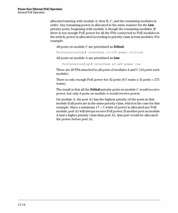
allocated starting with module A, then B, C, and the remaining modules in order. Any remaining power is allocated in the same manner for the Low priority ports, beginning with module A though the remaining modules. If there is not enough PoE power for all the PDs connected to PoE modules in the switch, power is allocated according to priority class across modules. For example:
All ports on module C are prioritized as Critical.
ProCurve(config)# interface c1-c24 power critical
All ports on module A are prioritized as Low.
ProCurve(config)# interface a1-a24 power low
There are 48 PDs attached to all ports of modules A and C (24 ports each module).
There is only enough PoE power for 32 ports (8.5 watts x 32 ports = 273 watts).
The result is that all the Critical priority ports on module C would receive power, but only 8 ports on module A would receive power.
On module A, the port A1 has the highest priority of the ports in that module if all ports are in the same priority class, which is the case for this example. Since a minimum 17 + 5 watts of power is allocated per PoE module, port A1 will always receive PoE power. If another port on module A had a higher priority class than port A1, that port would be allocated the power before port A1.
11-14
Power Over Ethernet (PoE) OperationConfiguring PoE Operation
Mgmt-Titan-2.book Page 15 Tuesday, February 6, 2007 3:51 PM
Configuring PoE OperationIn the default configuration, PoE support is enabled on the Gig-T ports in a PoE module installed on the switch. The default priority for all ports is Low and the default power notification threshold is 80 (%). Using the CLI, you can:
■ Change the PoE priority level on individual PoE ports
■ Disable or re-enable PoE operation on individual PoE ports
■ Change the threshold for generating a power level notice
Changing the PoE Port Priority Level
Syntax: interface < port-list > power [ critical | high | low ]
Reconfigures the PoE priority level on < port-list >. For a given level,
ports are prioritized by port number in ascending order. For
example, if ports A1-A24 have a priority level of critical, port A1
has priority over ports A2-A24.
If there is not enough power available to provision all active PoE
ports at a given priority level, then the lowest-numbered port at that
level will be provisioned first, starting with module A, then B, C,
and so on. PoE priorities are invoked only when all active PoE ports
cannot be provisioned (supplied with PoE power).
• Critical: Specifies the highest-priority PoE support for < port-list >. The active PoE ports at this level are provisioned
before the PoE ports at any other level are provisioned. • High: Specifies the second priority PoE support for
< port-list >. The active PoE ports at this level are provisioned
before the Low priority PoE ports are provisioned.
• Low (the default): Specifies the third priority PoE support for < port-list >. The active PoE ports at this level are provisioned only
if there is power available after provisioning any active PoE
ports at the higher priority levels.
You can use one command to set the same priority level on PoE ports
in multiple modules. For example, to configure the priority to High
for ports c5-c10, C23-C24, D1-D10, and D12, you could use this
command:
ProCurve(config)# interface c5-c10,c23-c24,d1-d10,d12 power high
11-15
Power Over Ethernet (PoE) OperationConfiguring PoE Operation
Mgmt-Titan-2.book Page 16 Tuesday, February 6, 2007 3:51 PM
Disabling or Re-Enabling PoE Port Operation
Enabling Support for Pre-Standard Devices
The Series 5400zl and Series 3500yl switches also support some pre-802.3af devices. For a list of the devices supported, refer to the FAQs for your switch model.
Syntax: [no] interface < port-list > power
Re-enables PoE operation on < port-list > and restores the priority
setting in effect when PoE was disabled on < port-list >. The [no] form of the command disables PoE operation on < port-list >.
(Default: All PoE ports on the module are initially enabled for
PoE operation at Low priority. If you configure a higher priority,
this priority is retained until you change it.)
Note: Disabling all ports on a module allows the 22W of
minimum PoE power allocated for the module to be recovered and
used elsewhere. You must disable ALL ports in the module for this
to occur.
Syntax: [no] power pre-std-detect
Detects and powers pre-802.3af standard devices.
Note: This is enabled by default.
11-16
Power Over Ethernet (PoE) OperationConfiguring PoE Operation
Mgmt-Titan-2.book Page 17 Tuesday, February 6, 2007 3:51 PM
Changing the Threshold for Generating a Power Notice
This command specifies the PoE usage level (as a percentage of the
PoE power available on a module) at which the switch generates a
power usage notice. This notice appears as an SNMP trap and a
corresponding Event Log message, and occurs when a PoE module’s
power consumption crosses the configured threshold value. That is,
the switch generates a notice whenever the power consumption on
a module either exceeds or drops below the specified percentage of
the total PoE power available on the module.
This command configures the notification threshold for PoE power
usage on either a global or per-module (slot) basis.
Without the [slot < slot-identifier >] option, the switch applies one
power threshold setting on all PoE modules installed in the switch.
For example, suppose slots A, B, and C each have a PoE module
installed. In this case, executing the following command sets the
global notification threshold to 70% of available PoE power.
ProCurve(config)# power threshold 70With this setting, if module B is allocated 100 watts of PoE power
and is using 68 watts, and then another PD is connected to the
module in slot B that uses 8 watts, the 70% threshold of 70 watts is
exceeded. The switch sends an SNMP trap and generates this Event
Log message:
Slot B POE usage has exceeded threshold of 70 %.If the switch is configured for debug logging, it also sends the Event
Log message to the configured debug destination(s).
On any PoE module, if an increasing PoE power load (1) exceeds
the configured power threshold (which triggers the log message and
SNMP trap), and then (2) later decreases and drops below the
threshold again, the switch generates another SNMP trap, plus a
message to the Event Log and any configured Debug destinations.
11-17
Power Over Ethernet (PoE) OperationConfiguring PoE Operation
Mgmt-Titan-2.book Page 18 Tuesday, February 6, 2007 3:51 PM
Configuring Optional PoE Port Identifiers
The Configured Type field enables you to configure a unique identifier for PoE ports that helps to identify the intended use for a given PoE port. Such identifiers are useful when viewing PoE status with the following commands:
show power-management brief (page 11-22)
show power-management < port-list > (page 11-23)
To configure a unique identifier for one or more PoE ports, use the switch’s setmib command to change the identifier setting in the switch’s MIB (Manage-ment Information Base), as described in the following steps.
To continue the preceding example, if the PoE power usage on
the PoE module in slot B drops below 70%, another SNMP trap
is generated and you will see this message in the Event Log:
Slot B POE usage is below threshold of 70 %.For a message listing, refer to “PoE Event Log Messages” on page 11-30. (Default Global PoE Power Threshold: 80)By using
the [slot < slot-identifier >] option, you can specify different
notification thresholds for different PoE modules installed in
the switch. For example, you could set the power threshold for
a PoE module in slot “A” to 75% and the threshold for the
module in slot “B” to 68% by executing the following two
commands:
ProCurve(config)# power slot a threshold 75 ProCurve(config)# power slot b threshold 68Note that the last threshold command affecting a given slot
supersedes the previous threshold command affecting the
same slot. Thus, executing the following two commands in the
order shown sets the threshold for the PoE module in slot “D”
to 75%, but leaves the thresholds for any PoE modules in the
other slots at 90%.
ProCurve(config)# power threshold 90 ProCurve(config)# power slot d threshold 75(If you reverse the order of the above two commands, all PoE
modules in the switch will have a threshold of 90%.)
11-18
Power Over Ethernet (PoE) OperationConfiguring PoE Operation
Mgmt-Titan-2.book Page 19 Tuesday, February 6, 2007 3:51 PM
1. Use the walkmib pethPsePortType.< slot-# > command to determine the MIB-based port number for the port to which you want to assign a Configured Type identifier. On the 5406zl switch the slot numbering is as follows:
2. Use the setmib pethPsePortType.< slot-# >.< port-# > -D < identifier-string > command to configure the identifier you want for a specific port.
For example, suppose that you have a PoE Module installed in slot B and want to assign the identifier “Wireless-1” to port 1 in this slot. To do so, you would use the following commands:
Slot Slot NumberUsed in the MIB
A 1
B 2
C 3
D 4
E 5
F 6
11-19
Power Over Ethernet (PoE) OperationConfiguring PoE Operation
Mgmt-Titan-2.book Page 20 Tuesday, February 6, 2007 3:51 PM
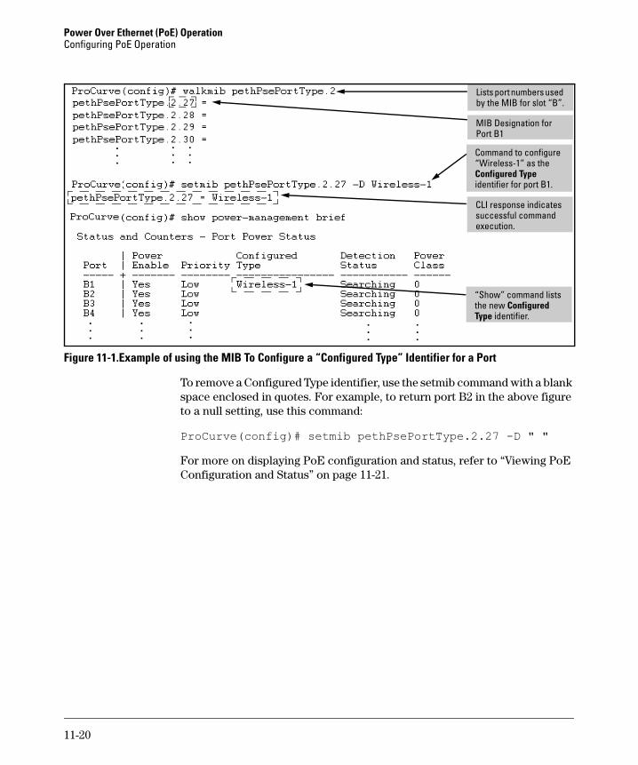
Figure 11-1.Example of using the MIB To Configure a “Configured Type” Identifier for a Port
To remove a Configured Type identifier, use the setmib command with a blank space enclosed in quotes. For example, to return port B2 in the above figure to a null setting, use this command:
“Show” command lists the new Configured Type identifier.
11-20
Power Over Ethernet (PoE) OperationViewing PoE Configuration and Status
Mgmt-Titan-2.book Page 21 Tuesday, February 6, 2007 3:51 PM
Viewing PoE Configuration and StatusDisplaying the Switch’s Global PoE Power Status
For example, in the default PoE configuration, when the switch is running with several ports supporting PD loads on the PoE module in slot A, show power-management displays data similar to the following:
Figure 11-2. Example of Show Power-Management Output
Syntax: show power-management
Displays the switch’s global PoE power status, including:
• Maximum Power: Lists the maximum PoE wattage available to
provision active PoE ports on the switch.
• Power In Use: Lists the amount of PoE power presently in use.
• Operational Status: Indicates whether PoE power is available on
the switch. (Default: On ; shows Off if PoE power is not available.
Shows Faulty if internal or external PoE power is oversubscribed
or faulty.)
• Usage Threshold (%): Lists the configured percentage of available
PoE power provisioning the switch must exceed to generate a
usage notice in the form of an Event Log message and an SNMP
trap. If this event is followed by a drop in power provisioning
below the threshold, the switch generates another SNMP trap and
Event Log message. Event Log messages are also sent to any
Power Over Ethernet (PoE) OperationViewing PoE Configuration and Status
Mgmt-Titan-2.book Page 22 Tuesday, February 6, 2007 3:51 PM
Displaying an Overview of PoE Status on All Ports
For example, show power-management brief displays this output:
Syntax: show power-management brief
Displays the following port power status:
• Port: Lists all PoE-capable ports on the switch.
• Power Enable: Shows Yes for ports enabled to support PoE (the
default) and No for ports on which PoE is disabled.• Priority: Lists the power priority (Low, High, and Critical)
configured on ports enabled for PoE. (For more on this topic,
refer to the power command description under “Configuring PoE Operation” on page 11-15.)
• Configured Type: If configured, shows the user-specified
identifier for the port. If not configured, the field is empty.
Refer to “Configuring Optional PoE Port Identifiers” on page 11-18.
• Detection Status: – Searching: The port is trying to detect a PD connection.
– Delivering: The port is delivering power to a PD.
– Disabled: On the indicated port, either PoE support is
disabled or PoE power is enabled but the PoE module does
not have enough power available to supply the port’s power
needs.
– Fault: The switch detects a problem with the connected PD.• Power Class: Shows the 802.3af power class of the PD detected
on the indicated port. Classes include:
0: 0.44w to 12.95w 1: 0.44w to 3.84w
2: 3.84w to 6.49w
3: 6.49w to 12.95w
4: reserved
• Other fault: The switch has detected an internal fault that
prevents it from supplying power on that port.
11-22
Power Over Ethernet (PoE) OperationViewing PoE Configuration and Status
Mgmt-Titan-2.book Page 23 Tuesday, February 6, 2007 3:51 PM
Figure 11-3. Example of Show Power-Management Brief Output
Displaying the PoE Status on Specific Ports
Ports C1 through C4 are delivering power. The remaining ports are available to supply power, but currently do not detect a connected PD.
Syntax: show power-management < port-list >
Displays the following PoE status and statistics (since the last
reboot) for each port in < port-list >:• Power Enable: Shows Yes for ports enabled to support PoE (the
default) and No for ports on which PoE is disabled. Note that
for ports on which power is disabled, this is the only field
displayed by show power-management < port-list >.
• Priority: Lists the power priority (Low, High, and Critical)
configured on ports enabled for PoE. (For more on this topic,
refer to the power command description under “Configuring PoE Operation” on page 11-15.)
• Detection Status: – Searching: The port is available to support a PD.
– Delivering: The port is delivering power to a PD.
– Disabled: PoE power is enabled on the port but the PoE
module does not have enough power available to supply
the port’s power needs.
• Fault: The switch detects a problem with the connected PD.
• Other Fault: The switch has detected an internal fault that
prevents it from supplying power on that port.
• Over Current Cnt: Shows the number of times a connected PD
has attempted to draw more than 15.4 watts. Each
occurrence generates an Event Log message.
— Continued —
11-23
Power Over Ethernet (PoE) OperationViewing PoE Configuration and Status
Mgmt-Titan-2.book Page 24 Tuesday, February 6, 2007 3:51 PM
For example, if you wanted to view the PoE status of ports C1 and D5, you would use show power-management c1,d5 to display the data:
Figure 11-4. Example of Show Power-Management < port-list > Output
Syntax: show power-management < port-list > (Continued)
• Power Denied Cnt: Shows the number of times PDs requesting power on the port have been denied due to insufficient power available. Each occurrence generates an Event Log message.
• Voltage: The total voltage, in dV, being delivered to PDs.• Power: The total power, in mW, being delivered to PDs.• Configured Type: If configured, shows the user-specified
identifier for the port. If not configured, the field is empty. Refer to “Configuring Optional PoE Port Identifiers” on page 11-18.
• Power Class: Shows the power class of the PD detected on the
indicated port. Classes include:
0: 0.44w to 12.95w
1: 0.44w to 3.84w
2: 3.84w to 6.49w
3: 6.49w to 12.95w
4: reserved
• MPS Absent Cnt: This value shows the number of times a
detected PD has no longer requested power from the port.
Each occurrence generates an Event Log message. (“MPS”
refers to the “Maintenance Power Signature.” Refer to “PoE Terminology” on page 11-4.)
• Short Cnt: Shows the number of times the switch provided
insufficient current to a connected PD.
• Current: The total current, in mA, being delivered to PDs.
Example of command output for a port on which power is enabled.
Example of command output for a port on which power is disabled.
11-24
Power Over Ethernet (PoE) OperationPlanning and Implementing a PoE Configuration
Mgmt-Titan-2.book Page 25 Tuesday, February 6, 2007 3:51 PM
Planning and Implementing a PoE Configuration
This section provides an overview of some considerations for planning a PoE application. For additional information on this topic, refer to the ProCurve
PoE Planning and Implementation Guide which is available on the ProCurve Networking web site at www.procurve.com. (Click on technical support, then Product manuals (all)).
Some of the elements you may want to consider for a PoE installation include:
■ Port assignments to VLANs
■ Use of security features
■ Power requirements
This section can help you to plan your PoE installation. If you use multiple VLANs in your network, or if you have concerns about network security, you should read the first two topics. If your PoE installation comes close to (or is likely to exceed) the system’s ability to supply power to all devices that may request it, then you should also read the third topic. (If it is unlikely that your installation will even approach a full utilization of the PoE power available, then you may find it unnecessary to spend much time on calculating PoE power scenarios.)
Assigning PoE Ports to VLANs
If your network includes VLANs, you may want to assign various PoE-config-ured ports to specific VLANs. For example, if you are using PoE telephones in your network, you may want to assign ports used for telephone access to a VLAN reserved for telephone traffic.
Applying Security Features to PoE Configurations
You can utilize security features built into the switch to control device or user access to the network through PoE ports in the same way as non-PoE ports.
11-25
Power Over Ethernet (PoE) OperationPlanning and Implementing a PoE Configuration
Mgmt-Titan-2.book Page 26 Tuesday, February 6, 2007 3:51 PM
■ MAC Address Security: Using Port Security, you can configure each switch port with a unique list of MAC addresses for devices that are authorized to access the network through that port. For more infor-mation, refer to the chapter titled "Configuring and Monitoring Port Security" in the Access Security Guide for your switch.
■ Username/Password Security: If you are connecting a device that allows you to enter a username and password that is forwarded to a networked server for authentication, then you can also configure the following security features:
– Local username and password– TACACS+– RADIUS Authentication and Accounting– 802.1X Authentication
For more information on security options, refer to the latest edition of the Access Security Guide for your switch. (The ProCurve Networking web site offers the latest version of all ProCurve product publications. Refer to “Getting Documentation From the Web” on page 1-7.)
Assigning Priority Policies to PoE Traffic
You can use the configurable QoS (Quality of Service) features in the switch to create prioritization policies for traffic moving through PoE ports. Table 11-4 lists the available classifiers and their order of precedence.
Table 11-4. Classifiers for Prioritizing Outbound Packets
For more on this topic, refer to the chapter titled “Quality of Service: Managing Bandwidth More Effectively” in the Advanced Traffic Management Guide for your switch.
Priority QoS Classifier
1 UDP/TCP Application Type (port)
2 Device Priority (destination or source IP address)
3 IP Type of Service (ToS) field (IP packets only)
4 VLAN Priority
5 Incoming source-port on the switch
6 Incoming 802.1p priority (present in tagged VLAN environments)
11-26
Power Over Ethernet (PoE) OperationPlanning and Implementing a PoE Configuration
Mgmt-Titan-2.book Page 27 Tuesday, February 6, 2007 3:51 PM
Calculating the Maximum Load for a PoE Module
The maximum power available for a PoE module depends on the type of power supplies used. ProCurve recommends that if you use more than one power supply, use the same type of power supplies in your PoE implementation, that is, two J8712A power supplies supplying 273 watts each for a total of 546 watts of PoE power, or two J8713A power supplies supplying 900 watts of PoE power each for a total of 1800 watts of PoE power.
When you connect the first PD to a PoE port, the PoE module must have a minimum of 17 watts of PoE power available in order to detect and supply power to the device. Each PoE module is allocated a minimum of 22 watts of PoE power—17 watts for detection and additional 5 watts for variations in any applied power loads. Depending on the amount of power the power supply device delivers to a specific PoE module, there may or may not always be enough power available to connect and support PoE operation on all 24 Gig-T ports in a PoE module. PoE power is “available” if it is either not currently in use or can be acquired by (automatically) removing PoE power from another, lower-priority port.
After an appliance is connected to a PoE port, the switch reduces the power requirement for that port from the initial 17 watts to the actual power level the appliance requires.
Thus, after you have connected all but the last planned appliance to a PoE module, there must be a minimum of 17 watts of unused PoE power available on the module to support adding the final appliance. If you are using one J8712A power supply powering one PoE module only (all 273 watts are available to that module), the power is calculated as follows:
n= the total number of appliances you want to connect to one PoE module
and
w = the total PoE power required to operate (n - 1) appliances
then, the following must be true:
or
w 17 273≤+
273 17–( ) w≥
11-27
Power Over Ethernet (PoE) OperationPlanning and Implementing a PoE Configuration
Mgmt-Titan-2.book Page 28 Tuesday, February 6, 2007 3:51 PM
Therefore, you can power 17 ports at full power (273 watts - 17 watts = 256 watts ÷ 15.4 watts per port = 16.6 + 1 ports). In actual practice, the PD will mostly likely use less than 15.4 watts of PoE power, allowing you to attach more than 17 PDs.
For example, suppose you have 24 identical appliances to connect to a PoE module receiving 273 watts of PoE power. For this example, each appliance requires 8.5 watts to operate. In this case, the module would support 24 appliances at any given time because there is enough unused power to meet the minimum of 17 watts required to support the initial power-up of the 24th appliance. That is, 273 - (24 x 8.5) = 69 watts of unused power.
When a Power Supply Fails
You must have two power supplies installed to maintain at least some amount of PoE power or to keep the switch itself operational if one power supply fails. If you have two J812A power supplies installed supplying 273 watts of PoE power each (total = 546 watts), then 273 watts of PoE power will be available to continue supplying PoE power to ports in priority order if one supply fails.
If you have two J8713A power supplies installed supplying 900 watts of PoE power each (total =1800 watts), then 900 watts of PoE power will be available to continue supplying PoE power to ports in priority order if one power supply fails.
If you have a mixed power supply configuration with one J8712A power supply supplying 273 watts of PoE power, and one J8713A power supply supplying 900 watts of PoE power, a total of 1173 watts of PoE power is available. If a power supply fails, the switch will continue to supply 273 watts of PoE power to the ports with the highest priority (if all ports are the same priority level, power is allocated to the lowest port number first) and power down any ports using power above the total of 273 watts. The switch then determines which power supply actually failed, the larger J8713A or the smaller J8712A. If the smaller power supply failed, the switch restores power to the ports in priority order until the available 900 watts is used.
If the larger J8713A power supply fails, then only 273 watts of PoE power is available and the other ports remain shut down in priority order.
For additional information about planning your PoE configuration, refer to the PoE Planning and Implementation Guide, which is available from the ProCurve Networking web site at www.procurve.com. (Click on technical support, then Product manuals (all).)
11-28
Power Over Ethernet (PoE) OperationPoE Operating Notes
Mgmt-Titan-2.book Page 29 Tuesday, February 6, 2007 3:51 PM
PoE Operating Notes
■ It is important to remember that power is allocated dynamically between PoE modules, with 22 watts of power allocated to each PoE module in each slot. This ensures that 17 watts of PoE power is available for the initial power-up of the last PD connected. The additional 5 watts smooth out any power fluctuations. To best utilize the allocated PoE power, spread your connected PoE devices as evenly as possible across modules.
■ To cycle the power on a PD receiving power from a PoE port on the switch, disable, then re-enable the power to that port. For example, to cycle the power on a PoE device connected to port 1 on a PoE module installed in slot D:
ProCurve(config)# no interface d1 powerProCurve(config)# interface d1 power
■ Disabling all PoE ports in a module allows you to recover the 22 watts of PoE power allocated to the module for use in other modules. You must disable ALL ports in the module for this to occur.
11-29
Power Over Ethernet (PoE) OperationPoE Operating Notes
Mgmt-Titan-2.book Page 30 Tuesday, February 6, 2007 3:51 PM
PoE Event Log Messages
PoE operation generates these Event Log messages. You can also configure the switch to send these messages to a configured debug destination (terminal device or SyslogD server).
“Informational” PoE Event-Log Messages
Message Meaning
I < MM/DD/YY > < HH:MM:SS > <chassis|ports>
Message header, with severity, date, system time, and system module type (chassis or ports). For more information on Event Log operation, including severity indicators, refer to “Using the Event Log To Identify Problem Sources” on page C-26
Slot < slot-id > POE usage is below configured threshold of < 1 - 99 > %
Indicates that POE usage on the module in the indicated slot has decreased below the threshold specified by the last execution of the power threshold command affecting that module. This message occurs if, after the last reboot, the PoE demand on the module exceeded the power threshold and then later dropped below the threshold value.
port < port-id > applying power to PD A PoE device is connected to the indicated port and receiving power.
port < port-id > PD detected The switch has detected a PoE device connected to the indicated port.
Slot <slot-id> software update started on PoE controller <controller-id>
A module needs to have its PoE firmware updated and the software begins the update process. On Series 5400zl switches the controller-id is always “1”
Slot <slot-id> software update completed on PoE controller <controller-id>
A module has its PoE firmware updated and the software has finished this process.
11-30
Power Over Ethernet (PoE) OperationPoE Operating Notes
Mgmt-Titan-2.book Page 31 Tuesday, February 6, 2007 3:51 PM
“Warning” PoE Event-Log Messages
Message Meaning
W < MM/DD/YY > < HH:MM:SS > chassis Message header, with severity, date, system time, and system module type. For more information on Event Log operation, including severity indicators, refer to “Using the Event Log To Identify Problem Sources” on page C-26“.
Slot < slot-id > POE usage has exceeded threshold of < 1 - 99 > %
Indicates that POE usage in the indicated slot has exceeded the configured threshold for the module, as specified by the last execution of the power threshold or power slot < slot-id > threshold command. (Note that the switch also generates an SNMP trap for this event.)
Port < port-id > PD Denied power due to insufficient power allocation.
There is insufficient power available to power the PD on the indicated port and the port does not have sufficient PoE priority to take power from another active PoE port.
Port < port-id > PD Invalid Signature indication
The switch has detected a non-802.3af-compliant device on the indicated port. This message appears for all non-802.3af devices connected to the port, such as other switches, PC-NICs, etc.
Port < port-id > PD MPS Absent indication The switch no longer detects a device on < port-id >. The device may have been disconnected, powered down, or stopped functioning.
Port < port-id > PD Other Fault indication There is a problem with the PD connected to the port.
Port < port-id > PD Over Current indication
The PD connected to < port-id > has requested more than 15.4 watts of power. This may indicate a short-circuit or other problem in the PD.
50v Power Supply is faulted. Failures:x
Internal power supply has faulted.
50v Power Supply is OK. Failures:x Internal power supply is now OK.
11-31
Power Over Ethernet (PoE) OperationPoE Operating Notes
Mgmt-Titan-2.book Page 32 Tuesday, February 6, 2007 3:51 PM