x alliedtelesis.com C613-22091-00 REV A T echnical Guide Technical Guide Feature Overview and Configuration Guide Introduction This guide provides an introduction to Power over Ethernet technology, the PoE standards, PoE devices, and how to configure PoE on your switch. PoE is a method of supplying power to network devices by utilizing the same cabling used to carry network traffic. PoE is appropriate for devices that have a low power consumption—PDs (Powered Devices) such as wireless access points, IP telephones, Webcams, and even other Ethernet switches. The benefits of PoE are lower installation costs and greater flexibility of device placement. For example, deploying IP Video Security cameras on ceilings and building perimeters can be expensive if separate Ethernet cabling and power outlets are required. With PoE, you can install PoE-compatible devices wherever they are needed without having to worry about whether there are power sources nearby. PoE PoE distributes both data and power over the same cabling. This eliminates the need for having one set of cables and outlets for data, and another set for power. Also, because the voltage and power requirements are much lower than for mains powered devices, the cabling and installation costs are significantly reduced. There are two types of equipment involved in a PoE installation: Power Sourcing Equipment (PSE), such as an Ethernet LAN switch, supplies power to the cable together with the data. Powered Devices (PDs), such as Wireless Access Points or IP Phones, receive power and data over this same cabling. The PSE employs various methods of power classification (depending on the standard) for distinguishing compatible PDs from non-compatible devices and will only provide power to compatible PDs, based on their PoE device class. The PSE continuously monitors the PDs and stops providing power when it is no longer requested or it detects an overload or short circuit condition on a port. Power Over Ethernet (PoE)
Example show command output................................................................................21
Remotely monitoring power for all connected PDs....................................................23
Activating the redundant power budget .....................................................................23
Products and software version that apply to this guide | Page 3
Advantages of PoE
Network devices require both a data connection and a power supply. Just as standard
phones are supplied power and also communicate over the same wiring, the same
provision can be made for Ethernet network devices. Benefits and applications of PoE
switches include:
Cost Saving: PDs only require a single Ethernet cable for the network and power
connection. This feature reduces the power line installation cost for electrical wiring,
conduits, and power outlets. PoE provides maximum flexibility for device installation.
You can install PDs almost anywhere without the need for DC/AC power inputs.
Reliability: Using a single cabling system for power and data improves network
reliability and deployment flexibility.
Safety: You can set the power limitation for each port on the PoE switch. Power limit
configuration can protect PoE switches from providing too much power to a single PD,
even when requested by the PD.
Security: By remote management of the PSE, the administrator can power on or power
off the PD remotely for added protection. The network administrator can also disable
the PSE when it is not in use or is accessed by unauthorized PDs.
Further advantages of PoE include:
PD installation is simplified and space is saved.
PD placement is not limited to nearby power sources.
PDs can be easily moved to wherever there is LAN cabling.
Little to no extra management complexity.
A UPS (Uninterruptible Power Supply) can guarantee power to devices even during
mains failure.
Page 4 | Advantages of PoE
PoE standards
Two PoE standards are presently defined by the Institute of Electrical and Electronics
Engineers (IEEE):
IEEE 802.3af Power Ethernet standard
Approved 2003.
Supplies 15.94W of power of which 12.95 W is available to each powered device.
Superseded by IEEE IEEE802.3at.
IEEE 802.3at Power Ethernet standard—known as PoE+
Approved 2009.
Supplies 30W of power of which 25.5 W is available to each powered device.
For more information on this method, refer to "LLDP-MED (TIA-1057) with PoE" on page 11.
A third standard is currently under development, and expected to be published in 2017.
This is:
IEEE 802.3bt Power Ethernet standard—known as PoE++
Supplies 60W of power, of which 51W is available to each powered device (up to 90W, of which 71W is available to each powered device, for some device classes).
Uses all 8 wires in the cable
Adds new power classes: 5-8
Extends PoE to 10GbaseT
In advance of this standard, Allied Telesis has developed High-power PoE mode on IE300
Series switches to provides similar functionality. See "Configuring high-power PoE
mode" on page 15.
This guide uses the term PoE for all these IEEE standards.
The major differences between the standards relate to the power that the PDs are allowed
to consume, and the ability to dynamically manage the power supplied to each PD.
The following table summarizes the major differences in terms of their capabilities. Note
that the maximum power available to the PD is less than the power supplied by the PSE.
This is because the system provides the 'extra' power to compensate for line loss.
PoE standards | Page 5
STANDARD PSE TYPE POWER SUPPLIED BY PSE
POWER AVAILABLE TO PD
CABLING MAX CABLE LENGTH
POWER OVER NOMINAL CURRENT
IEEE 802.3af Type 1 15.4W 12.95WCAT 3 or better
100M 2 pairs 350mA
IEEE 802.3at Type 2 30W 25.5WCAT 5 or better
100M 2 pairs 600mA
IEEE802.3bt Type 3 60W 51WCAT 5 or better 100M
2 pairs class 0-44 pairs class 0-44 pairs class 5-6
600mA
IEEE802.3bt Type 4 90W 71WCAT 5 or better
100M 4 pairs class 7-8 1000mA
How PoE works
PoE requires little configuration or management. The PSE automatically determines
whether a device connected to a port is a powered device or not, and can determine the
power class of the device
Power Device (PD) Discovery
The first step for PSE equipment is to determine whether a device plugged into a port is a
valid Powered Device (PD). If it is, it will require power as well as network communication
through the attached LAN cable.
Device detection involves applying a DC voltage between the transmit and receive wire
pairs, and measuring the received current. The PSE will check for the presence of PDs on
connected ports at regular intervals, so that power can be removed when a PD is no
longer connected.
If the device connected to a port is not a PD (i.e. it obtains its power from another source),
then the port will function as a regular Ethernet port, without PoE. The PoE feature
remains activated on such ports but no power is delivered to the devices.
Legacy Powered Device (PD) Detection
The AlliedWare PlusTM implementation of PoE offers two methods of PD detection. The
first method uses the IEEE 802.3af and IEEE 802.3at standards resistance and
capacitance measurements as described earlier. The second option is to support legacy
PDs that were designed before the IEEE standard was finalized. This involves measuring
for a large capacitance value to confirm the presence of a legacy PD. The IEEE method
will be tried first and failing the discovery of a valid PD the legacy capacitance
measurement will be tried.
By default, legacy PD detection is enabled on all ports. To disable legacy PD detection,
use the command:
awplus(config)# no power-inline allow-legacy
Page 6 | How PoE works
PD CLASS POWER AVAILABLE AT PD MAX POWER OUTPUT FROM A SWITCH PORT
0 0.44 W to 12.95 W 15.4 W
1 0.44 W to 3.84 W 4.0 W
2 3.84 W to 6.49 W 7.0 W
3 6.49 W to 12.95 W 15.4 W
4 12.95 W to 25.5 W 30 W
POE DEVICE POE POWER REQUIREMENT
IP phone 3 W-6 W
Wireless access point 4 W-11 W
IP security camera 5 W-12 W
Wireless Access Point (with LLDP-MED support) 12 W-24 W
Pan Tilt and Zoom powered IP security camera 12 W-24 W
Power Classes
Once a PD is discovered, the PSE initiates a PD classification test by applying a DC
voltage to the port. If the PD supports optional power classification it will apply a load to
the line to indicate to the PSE the classification the device requires.
Since PDs may require differing power ranges, the standards classifies PDs according to
their power consumption. By providing the PSE with its power range, the PD allows the
PSE to supply power with greater efficiency. The power classes are as follows:
Once the PSE has detected the PD’s power class, it can manage the power allocation by
subtracting the PD’s class maximum value from the overall power budget. This allows for
control and management of power allocation when there is not enough power available
from the PSE to supply maximum power to all ports. Any unclassified PD is considered to
be a class 0 device.
To view the PD class that has been configured for each PoE port, use the following
command:
awplus# show power-inline
Some common PoE device power requirements are:
How PoE works | Page 7
Power through the cable
An Ethernet cable has four twisted pairs. The standards describe two methods for
applying PoE over the twisted pairs, termed “alternatives A and B”.
Alternative A applies power using pins 1, 2, 3, and 6. For 10/100M connections, this
means it supplies power over the data-carrying cable pairs.
Alternative B applies the power using pins 4, 5, 7, and 8. For 10/100M connections, this
means it supplies power over the spare cable pairs.
For Gigabit and 10 Gigabit transmission, all four pairs are used for data but the same PoE
pinning alternatives apply.
Most devices running AlliedWare Plus use alternative A to supply power to the PDs,
except for:
x310 and GS900MPX Series switches, which use alternative B, and
IE300-12GP switches, which use alternative A on ports 5-8, and either or both
alternatives on ports 9-12. This is because ports 9-12 support high-power mode (see
"Configuring high-power PoE mode" on page 15).
An IEEE compliant PD should be able to receive PoE using either of the two wiring
methods.
Cable types
The cable requirements for ports operating at 10 or 100Mbps are given in the table below:
Cable Type10 Mbps
100Mbps
NON-POE POE POE+ NON-POE POE POE+
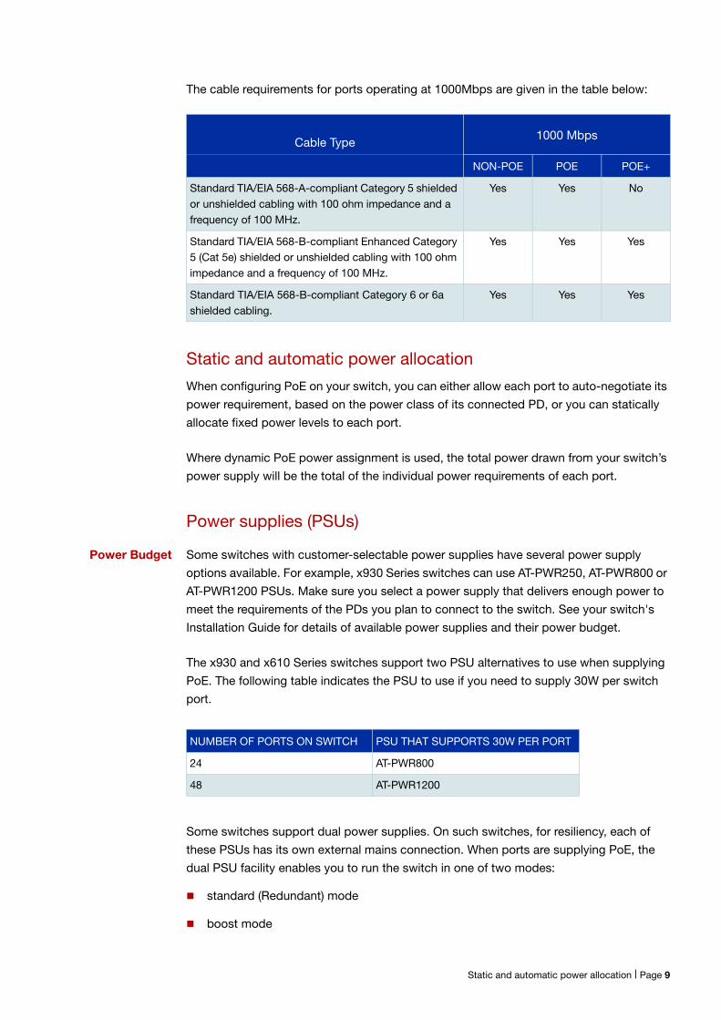
Standard TIA/EIA 568 A compliant Category 5 shielded or unshielded cabling with 100 ohm impedance and a frequency of 100 MHz.
Yes Yes No Yes Yes No
Standard TIA/EIA 568-B compliant Enhanced Category 5 (Cat 5e) shielded or unshielded cabling with 100 ohm impedance and a frequency of 100 MHz.
Yes Yes Yes Yes Yes Yes
Standard TIA/EIA 568 B compliant Category 6 or 6a shielded cabling.
Yes Yes Yes Yes Yes Yes
Page 8 | Cable types
NON-POE POE POE+
Standard TIA/EIA 568-A-compliant Category 5 shielded or unshielded cabling with 100 ohm impedance and a frequency of 100 MHz.
Yes Yes No
Standard TIA/EIA 568-B-compliant Enhanced Category 5 (Cat 5e) shielded or unshielded cabling with 100 ohm impedance and a frequency of 100 MHz.
Yes Yes Yes
Standard TIA/EIA 568-B-compliant Category 6 or 6a shielded cabling.
Yes Yes Yes
NUMBER OF PORTS ON SWITCH PSU THAT SUPPORTS 30W PER PORT
24 AT-PWR800
48 AT-PWR1200
The cable requirements for ports operating at 1000Mbps are given in the table below:
Static and automatic power allocation
When configuring PoE on your switch, you can either allow each port to auto-negotiate its
power requirement, based on the power class of its connected PD, or you can statically
allocate fixed power levels to each port.
Where dynamic PoE power assignment is used, the total power drawn from your switch’s
power supply will be the total of the individual power requirements of each port.
Power supplies (PSUs)
Power Budget Some switches with customer-selectable power supplies have several power supply
options available. For example, x930 Series switches can use AT-PWR250, AT-PWR800 or
AT-PWR1200 PSUs. Make sure you select a power supply that delivers enough power to
meet the requirements of the PDs you plan to connect to the switch. See your switch's
Installation Guide for details of available power supplies and their power budget.
The x930 and x610 Series switches support two PSU alternatives to use when supplying
PoE. The following table indicates the PSU to use if you need to supply 30W per switch
port.
Some switches support dual power supplies. On such switches, for resiliency, each of
these PSUs has its own external mains connection. When ports are supplying PoE, the
dual PSU facility enables you to run the switch in one of two modes:
standard (Redundant) mode
boost mode
Cable Type1000 Mbps
Static and automatic power allocation | Page 9
In standard (Redundant) mode you apply power to both PSUs but restrict the power
demands of your PDs to be within the capabilities of a single power supply.
In boost mode you employ both PSUs, and utilize more power than is available from a
single PSU. However, if power from one of the PSUs is lost, the result will be a loss of PoE
capability to a number of ports - the exact number will depend on your particular port
configuration.
As an example, assume that a PoE switch has one AT-PWR1200 Power Supply, which has
a power budget of 740W for powered devices. Thus, the switch would have a total power
budget of 740W. Now assume the switch has two AT-PWR1200 Power Supplies. When
the power boost mode is enabled, the switch uses the PoE power from both supplies, for
a total power budget of 1440W. When the power boost mode is disabled, the switch has
an active PoE power of 740W and a redundant budget of the same amount. The switch
activates the redundant power budget only if the power supply providing the active power
budget fails or loses power.
Power threshold
The switch can be configured to send a Simple Network Management Protocol (SNMP)
trap to your management workstation. This enables the management workstation to
record an entry in the event log whenever the total power requirements of the powered
devices exceed the specified percentage of the total maximum power available on the
switch:
With the default setting of 80% applied, the switch sends an SNMP trap when the PoE
devices require more than 80% of the maximum available power on the switch. The
trap is: pethMainPowerUsageOnNotification from RFC 3621, Power Ethernet MIB.
The switch sends another SNMP trap when its power consumption drops below the
power limit threshold again. The trap is: pethMainPowerUsageOffNotification from RFC
3621, Power Ethernet MIB.
You can set the threshold to any value between 1% and 99%. The example "Remotely
monitoring power for all connected PDs" on page 22 changes the threshold to 75%.
Port prioritization
If the PDs connected to a switch require more power than the switch is capable of
delivering, the switch will deny power to some ports.
Port prioritization is the way the switch determines which ports are to receive power in the
event that the needs of the PDs exceed the available power resources of the switch.
Critical The highest priority level. Ports set to Critical level are guaranteed power before any ports
assigned to the other two priority levels. Ports assigned to the other priority levels receive
power only if all the Critical ports are receiving power. Your most critical powered devices
should be assigned to this level.
Page 10 | Power threshold
High The second highest level. Ports set to High level receive power only if all the ports set to
the Critical level are already receiving power.
Low The lowest priority level. This is the default setting. Ports set to Low level only receive
power if all the ports assigned to the other two levels are already receiving power.
If power needs to be removed from some of the PoE ports, where if for example, one of
the power supplies is disconnected; power will be removed from these ports in the order
Low, High, and Critical.
If there is not enough power to support all the ports set for a given priority level, power is
provided to the ports based on the switch port number:
SBx8100 switches: the port number, in ascending order, and on the slot number in the
chassis the PoE line card is installed in, in ascending order. Therefore, the lowest
numbered port on the lowest numbered line card has priority.
Other switches: the port number, in ascending order.
Power allocation is dynamic. Ports supplying power may stop powering a PD if the
switch's power capacity has reached maximum usage and new PD's are connected to
ports with a higher priority, which become active.
To ensure continued operation of a PD if the power resources of the switch are exceeded
you should install a PD to a lower numbered PoE port with the Critical priority level
configured.
LLDP-MED (TIA-1057) with PoE
The IEEE 802.1AB standard, Link Layer Discovery Protocol (LLDP) was designed to
provide a multi-vendor solution for the discovery of network devices and accurate
physical topology of how these devices are connected to one another. LLDP allows
network devices to advertise their basic configuration and device capabilities to other
network devices on the same LAN.
An extension to LLDP, Link Layer Discovery Protocol Media Endpoint Discovery (LLDP-
MED), allows Media Endpoint Devices, such as VoIP phones, to exchange configuration
information, including Power over Ethernet management.
LLDP-MED provides:
Fine grain PoE power allocation (1 watt granularity instead of wider power class bands)
which allows unused power to be allocated to other ports
Power priority of the PD being supplied power
Backup power conservation to extend UPS battery life
LLDP-MED (TIA-1057) with PoE | Page 11
If LLDP is enabled on the switch, LLDP will read the LLDP-MED TLV from the PD and pass
that info to the PoE system on the switch. PoE will then adjust the power limit on the port
and use that value as part of its power calculations.
Note that if you manually configure a power limit on the port, that manual value overrides
the LLDP value. So when determining the power limit for a port, the precedence is:
Manual configuration, then LLDP, then Class.
In other words, if you have not specified a manual limit, the LLDP-MED value is used, and
if LLDP-MED has not specified a limit, then the Class limit of the PD is used. For details on
PD Class limits, see "Power Classes" on page 7.
On IE300 Series switches, LLDP is only applied to the default pair of 60W enabled ports.
PoE ConfigurationAlliedWare Plus enables you to configure the following aspects of PoE:
PoE port management
PoE is enabled by default on all non-SFP (or SFP+) RJ-45 ports. You can connect either a
powered or non-powered device to a PoE-enabled port without having to re-configure the
port. This is because PD detection is carried out before any power is supplied to the
connected device.
PoE can be administratively enabled or disabled on each port using the power-inline
enable command in Interface Configuration mode. To disable PoE on a selected port, use
the command:
awplus(config-if)# no power-inline enable
A port that has PoE disabled will operate as a normal Ethernet port and will not supply
power to its cable connection.
Adding a description for a PoE port
You can add a description (for example, the device type) for a PoE port, which the switch
will display in certain show commands. Knowing the type of PD is useful when inspecting
PD Class power usage. The description entered will appear in the following commands
under Device, or Powered Device Type, for each port:
show power-inline interface
show power-inline interface detail
Page 12 | PoE port management
In the following example a description is added for the port1.0.2 to display the words
“Desk Phone” in the show output of the commands mentioned above.
Configuring capacity and priority on a port
The following commands set a higher priority and a lower maximum power for a port. This
prevents high powered PDs from being connected to a port reserved for low powered
PDs.
Many AlliedWare Plus switches are able to supply 802.3at (PoE+) power levels to all their
PoE-capable ports. This section describes how to control the power output for each port
if required.
COMMAND DESCRIPTION
awplus#
configure terminal Enter Global Configuration mode.
awplus(config)#
interface port1.0.2 Specify the port to be configured and enter Interface mode.
awplus(config-if)#
power-inline description Desk Phone The description “Desk Phone” will be displayed in all PoE show command output for port1.0.2.
awplus(config-if)#
exit Return to Global Configuration mode.
awplus(config)#
exit Return to Privileged Exec mode.
awplus#
show power-inline interface port1.0.2
Display the PoE status for port1.0.2 to confirm that your PoE configuration on the PSE has been successful. If a PD is connected to the configured PoE port then power consumption as well as power allocation values will display.
awplus#
copy running-config startup-config Save your running-config to the startup-config to keep your PoE configuration after a switch restart or reboot.
Configuring capacity and priority on a port | Page 13
Follow the configuration table below to configure port1.0.2:
Configuring HANP
IE200 and IE300 Series switches, running v5.4.6-2.1 or higher, support High Availability
Network Power (HANP). HANP enables the switches to perform actions such as software
upgrades without forcing the Powered Devices to power cycle. This means, for example,
If you are rebooting a switch connected to a PD such as a camera, HANP allows the
camera to buffer while the switch is rebooted.
You can configure HANP on a global or per port level. Enabling it globally enables it on all
PoE ports.
COMMAND DESCRIPTION
awplus#
configure terminal Enter Global Configuration mode.
awplus(config)#
interface port1.0.2 Specify the port to be configured and enter Interface mode.
awplus(config-if)#
power-inline priority high Specify a higher priority for the port than the default low setting.
awplus(config-if)#
power-inline max 4000 Specify the lowest available power that the PSE can supply to the PD: 4000 mW.
awplus(config-if)#
exit Return to Global Configuration mode.
awplus(config)#
exit Return to Privileged Exec mode.
awplus#
show power-inline interface port1.0.2
Display the PoE status for port1.0.2 to confirm that your PoE configuration on the PSE has been successful. If a PD is connected to the configured PoE port then power consumption as well as power allocation values will display.
awplus#
copy running-config startup-config
Save your running-config to the startup-config to keep your PoE configuration after a switch restart or reboot.
Page 14 | Configuring HANP
COMMAND DESCRIPTION
Enter Global Configuration mode
Enable HANP globally
Disable HANP globally
COMMAND DESCRIPTION
Enter Global Configuration mode
Enable HANP globally
Enter Interface Configuration mode
Disable HANP on port1.0.2
To enable and disable it globally, use the following commands:
To enable it on all PoE ports except port1.0.2, use the following commands:
You can see whether HANP is enabled globally and on each port by using the command
show power-inline. Note that the HANP status of individual ports only displays if HANP
has been enabled globally.
Configuring high-power PoE mode
IE300 Series switches support high-power PoE mode on ports 1.0.9-1.0.12. High-power
mode enables these ports to supply up to 60W of power per port.
To do this, the switch uses both the data and spare pairs to supply power, and supplies up
to 30W of power per pair. On the data pair, pins 1, 2, 3, and 6 can carry power. On the
spare pair, pins 4, 5, 7, and 8 can carry power.
By default, the data pair is enabled and the spare pair is disabled. Therefore, ports 1.0.9-
1.0.12 can supply a maximum of 30W of power by default.
The switch has a total PoE budget of 240W, divided between the 8 PoE ports.
awplus#
configure terminal
awplus(config)#
power-inline hanp
awplus(config)#
no power-inline hanp
awplus#
configure terminal
awplus(config)#
power-inline hanp
awplus(config)#
interface port1.0.2
awplus(config-if)#
no power-inline hanp
Configuring high-power PoE mode | Page 15
COMMAND DESCRIPTION
Enter Global Configuration mode
Enter Interface Configuration mode
Enable high-power mode.
COMMAND DESCRIPTION
Enter Global Configuration mode
Enter Interface Configuration mode
Enable high-power mode.
Set the maximum power level to 20W (20000 milliwatts). This sets the limit on each of the data and spare pairs to 20W, and therefore sets the limit on the port to 40W.
Enabling high-power mode
To enable high-power mode on ports 1.0.9-1.0.12, use the following commands:
Setting power maximums
You can set the maximum power level for each pair. You can give each pair the same
maximum power level or you can split the power unequally by giving each pair different
maximums. In most circumstances, it is unnecessary to split the power unequally.
To set the maximum power level on ports 1.0.9-1.0.12 to 40W, split equally between the
pairs, use the following commands:
awplus#
configure terminal
awplus(config)#
interface port1.0.9-1.0.12
awplus(config-if)#
power-inline pair enable
awplus#
configure terminal
awplus(config)#
interface port1.0.9-1.0.12
awplus(config-if)#
power-inline pair spare enable
awplus(config-if)#
power-inline max 20000
Page 16 | Configuring high-power PoE mode
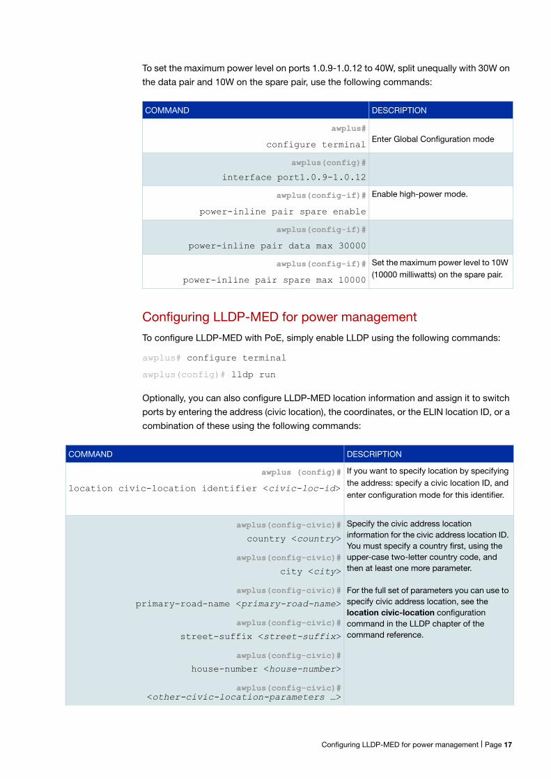
COMMAND DESCRIPTION
Enter Global Configuration mode
Enter Interface Configuration mode
Enable high-power mode.
Set the maximum power level to 30W (30000 milliwatts) on the data pair.
Set the maximum power level to 10W (10000 milliwatts) on the spare pair.
To set the maximum power level on ports 1.0.9-1.0.12 to 40W, split unequally with 30W on
the data pair and 10W on the spare pair, use the following commands:
Configuring LLDP-MED for power management
To configure LLDP-MED with PoE, simply enable LLDP using the following commands:
awplus# configure terminal
awplus(config)# lldp run
Optionally, you can also configure LLDP-MED location information and assign it to switch
ports by entering the address (civic location), the coordinates, or the ELIN location ID, or a
combination of these using the following commands:
awplus#
configure terminal
awplus(config)#
interface port1.0.9-1.0.12
awplus(config-if)#
power-inline pair spare enable
awplus(config-if)#
power-inline pair data max 30000
awplus(config-if)#
power-inline pair spare max 10000
COMMAND DESCRIPTION
awplus (config)#
location civic-location identifier <civic-loc-id>
If you want to specify location by specifying the address: specify a civic location ID, and enter configuration mode for this identifier.
Specify the civic address location information for the civic address location ID. You must specify a country first, using the upper-case two-letter country code, and then at least one more parameter.
For the full set of parameters you can use to specify civic address location, see the location civic-location configuration command in the LLDP chapter of the command reference.
Configuring LLDP-MED for power management | Page 17
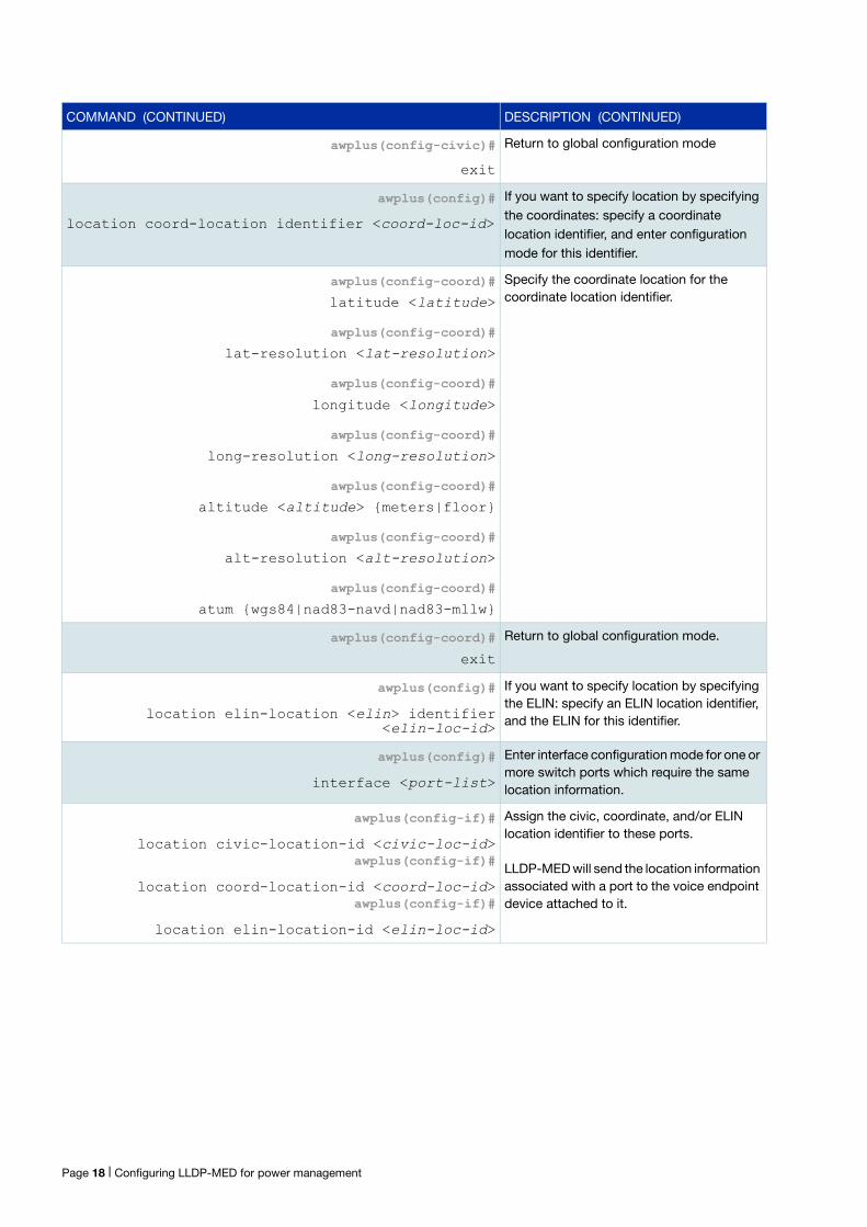
awplus(config-civic)#
exit
Return to global configuration mode
awplus(config)#
location coord-location identifier <coord-loc-id>
If you want to specify location by specifying the coordinates: specify a coordinate location identifier, and enter configuration mode for this identifier.
awplus(config-coord)#
latitude <latitude>
awplus(config-coord)#
lat-resolution <lat-resolution>
awplus(config-coord)#
longitude <longitude>
awplus(config-coord)#
long-resolution <long-resolution>
awplus(config-coord)#
altitude <altitude> {meters|floor}
awplus(config-coord)#
alt-resolution <alt-resolution>
awplus(config-coord)#
atum {wgs84|nad83-navd|nad83-mllw}
Specify the coordinate location for the coordinate location identifier.
awplus#show power-inline interface port1.0.9Interface/ Admin Pri Oper Power Device Class Max HANP Pair (mW) (mW)port1.0.9/D Enabled Low Powered 1822 n/a 0 15400 [C] Onport1.0.9/S Disabled Low Disabled 0 n/a n/a n/a On
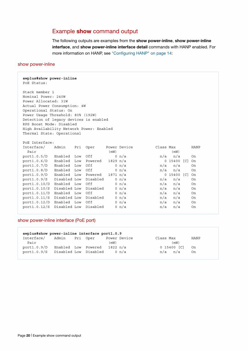
Example show command output
The following outputs are examples from the show power-inline, show power-inline
interface, and show power-inline interface detail commands with HANP enabled. For
more information on HANP, see "Configuring HANP" on page 14:
show power-inline
show power-inline interface (PoE port)
Page 20 | Example show command output
awplus#show power-inline interface port1.0.9 detailInterface port1.0.9/D Powered device type: n/a PoE admin: on Configured Priority: Low Actual Priority: Low Detection status: Powered High Availability Network Power: On Last negotiated time: Sat Jun 11 03:55:08 2016 Current power consumption: 1822 mW Powered device class: 0 Power allocated: 15400 mW (from powered device class) Powered pairs: Data
Interface port1.0.9/S Powered device type: n/a PoE admin: off Configured Priority: Low Actual Priority: Low Detection status: Disabled High Availability Network Power: On Powered pairs: Spare
show power-inline interface detail (PoE port)
Example show command output | Page 21
Remotely monitoring power for all connected PDs
Note that you will need to configure SNMP first for this. For more information on
configuring SNMP, see the following documents:
SNMP Feature Overview and Configuration Guide
Support for Allied Telesis Enterprise MIBs in AlliedWare Plus
The following procedure allows you to remotely monitor power usage for all connected
PDs, by sending traps when the power supplied exceeds 75% of the nominal PSE power
available.
Activating the redundant power budget
If the power supply providing the active power budget fails or loses power. For x610
series PoE switches connected to AT-RPS3000, see the power-inline rps boost command
and AT-RPS3000 hardware documentation to provide backup and boosted power:
configure terminal Enter Global Configuration mode.
awplus(config)#
service power-inline Enable PoE globally for the PSE. This will also enable PoE globally for all PoE ports on all connected stacked switches.
awplus(config)#
snmp-server enable trap power-inline Configure SNMP notification so an SNMP trap is sent when the power usage threshold is exceeded to trigger an alarm.
awplus(config)#
power-inline usage-threshold 75 Specify SNMP notifications are generated when the power supplied exceeds 75% of the nominal PSE power available.
awplus(config)#
exit Return to Privileged Exec mode.
awplus#
copy running-config startup-config Save your running-config to the startup-config to keep your PoE configuration after a switch restart or reboot.
C613-22091-00 REV A
NETWORK SMARTER
alliedtelesis.com
North America Headquarters | 19800 North Creek Parkway | Suite 100 | Bothell | WA 98011 | USA | T: +1 800 424 4284 | F: +1 425 481 3895
Asia-Pacific Headquarters | 11 Tai Seng Link | Singapore | 534182 | T: +65 6383 3832 | F: +65 6383 3830