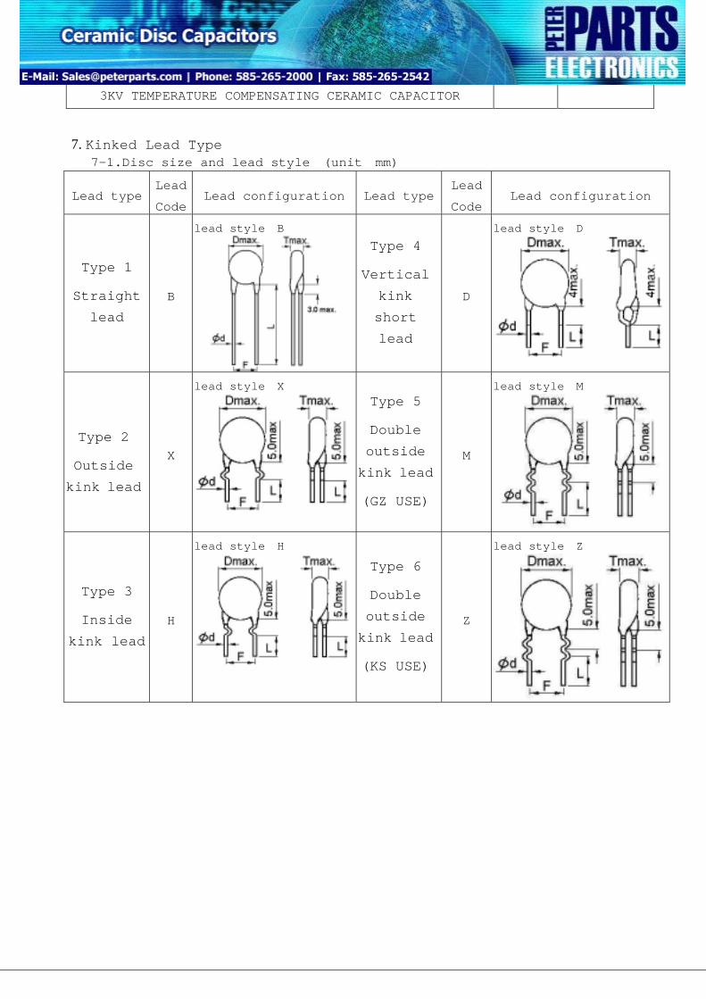
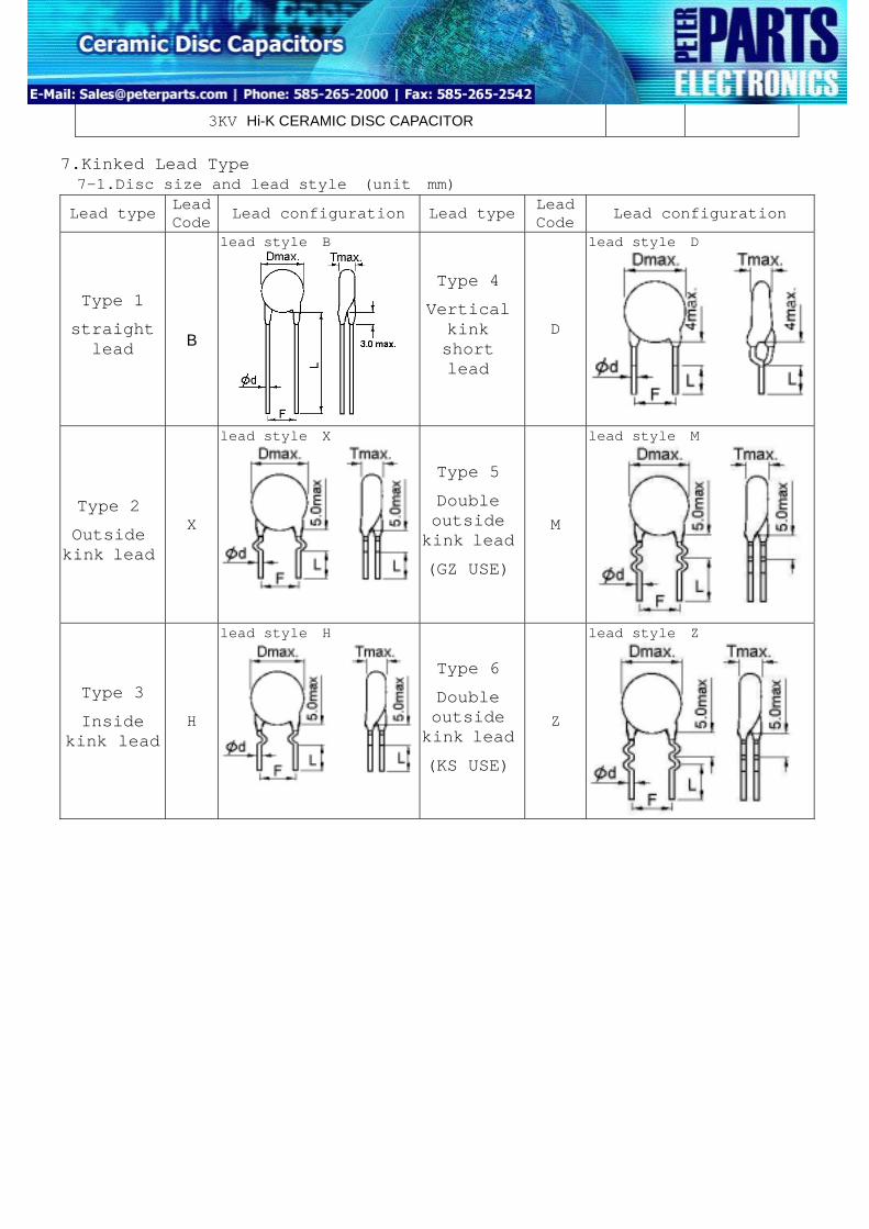
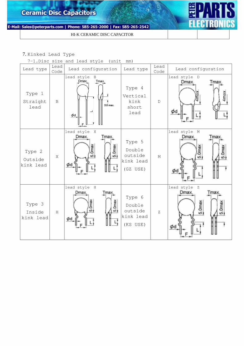
POE INTERNATIONAL CORPORATION D03-00-E-07 3KV TEMPERATURE COMPENSATING CERAMIC CAPACITOR 7. Kinked Lead Type: 7-1.Disc size and lead style:(unit:mm) Lead type Lead Code Lead configuration Lead type Lead Code Lead configuration Type 1 Straight lead B lead style:B Type 4 Vertical kink short lead D lead style:D Type 2 Outside kink lead X lead style:X Type 5 Double outside kink lead (GZ USE) M lead style:M Type 3 Inside kink lead H lead style:H Type 6 Double outside kink lead (KS USE) Z lead style:Z
Transcript
POE INTERNATIONAL CORPORATION D03-00-E-07
3KV TEMPERATURE COMPENSATING CERAMIC CAPACITOR
7. Kinked Lead Type: 7-1.Disc size and lead style:(unit:mm)
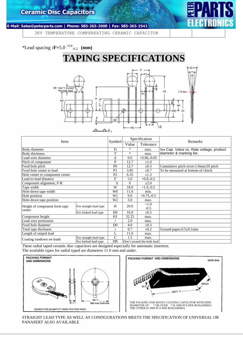
See Cap. Value vs. Rate voltage, product diameter & marking list.
Lead-wire diameter d 0.6 +0.06,-0.05 Pitch of component P 12.7 ±1.0 Food hole pitch P0 12.7 ±0.3 Cumulative pitch erroe:1.0mm/20 pitch Food hole center to lead P1 3.85 ±0.7 To be measured at bottom of clinch Hole center to component center P2 6.35 ±1.3 Lead-to-lead distance F 5.0 +0.8,-0.2 Component alignment, F-R △h 0 ±2.0 Tape width W 18.0 +1.0,-0.5 Hole-down tape width W0 11.0 min. Hole position W1 9.0 +0.75,-0.5 Hole-down tape position W2 3.0 max.
For straight lead type H 20.0 +1.0 -0.5 Height of component form tape
center For kinked lead type H0 16.0 ±0.5
Component height H1 32.25 max. Lead-wire protrusion l 2.0 max. Food hole diameter D0 4.0 ±0.3 Total tape thickness t 0.7 ±0.2 Ground paper:0.5±0.1mm Length of sniped lead L 11.0 max.
For straight lead type C 1.5 max. Coating rundown on leads For kinked lead type DR Don’t exceed the kink lead These radial taped ceramic disc capacitors are designed especially for automatic insertion. The available types for radial typed are diameters 11.0 mm and under. STRAIGHT LEAD TYPE AS WELL AS CONFIGURATIONS MEETS THE SPECIFICATION OF UNIVERSAL OR PANASERT ALSO AVAILABLE
THE PACKING FOR EPOXY COATING CAPACITOR WITH DISK DIAMETER OF Φ7 OR OVERΦ7 IS 1000 PCS PER BOX(AMMO) THE OTHER IS 2000 PCS PER BOX(AMMO)
POE INTERNATIONAL CORPORATION D03-00-E-07
3KV TEMPERATURE COMPENSATING CERAMIC CAPACITOR
Appendix 1.
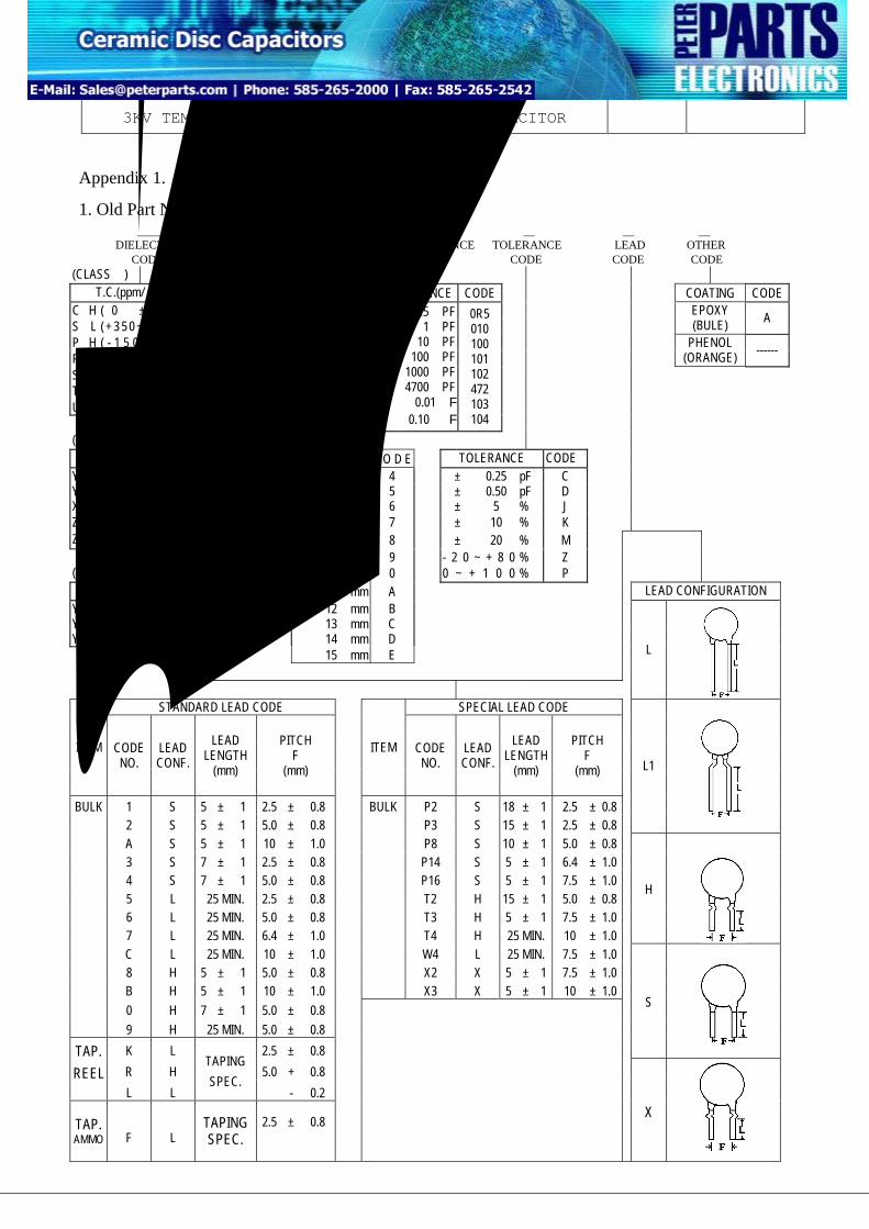
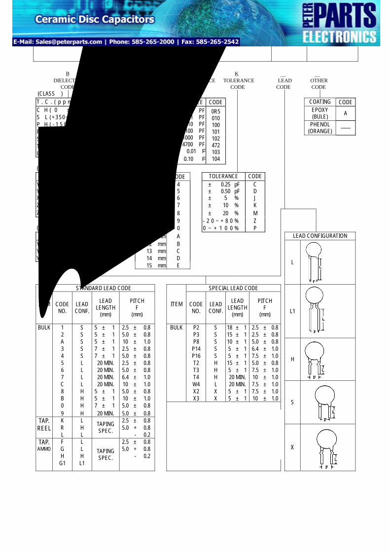
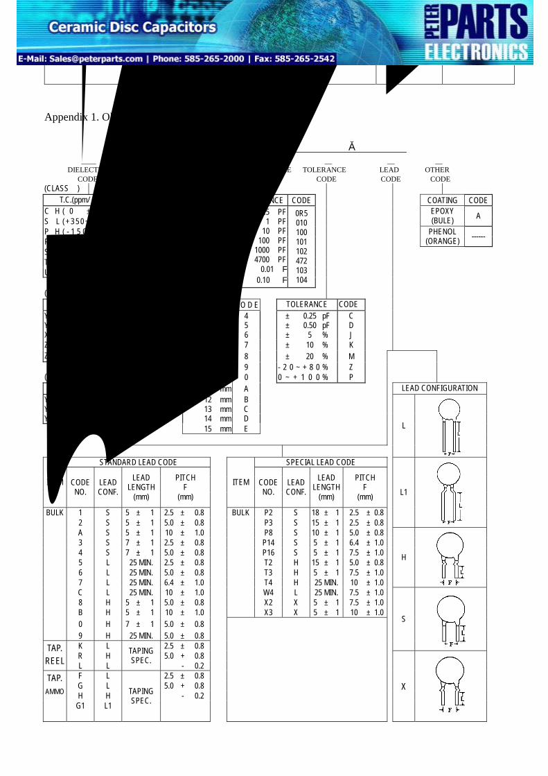
1. Old Part Number CH U 5 100 J H A DIELECTRIC VOLTAGE DIAMETER CAPACITANCE TOLERANCE LEAD OTHER CODE CODE CODE CODE CODE CODE CODE
S H ( - 3 3 0 ± 6 0 ) SH T H ( - 4 7 0 ± 6 0 ) TH U J ( - 7 5 0 ± 1 2 0 ) UJ
16 VDC 25 VDC 50 VDC
100 VDC 500 VDC 1 KVDC 2 KVDC 3 KVDC
B T U A C M M2 M3
0.5 PF 1 PF
10 PF 100 PF
1000 PF 4700 PF
0.01μF 0.10 μF
0R5 010 100 101 102 472 103 104
(CALSSⅡ) T.C. (△C%) C O D E D I A M E T E R C O D E TOLERANCE CODE
Y 5 E ( ± 4 . 7 % ) A 4 mm 4 ± 0.25 pF C Y 5 P ( ± 1 0 % ) B 5 mm 5 ± 0.50 pF D X 7 R ( ± 1 5 % ) X 6 mm 6 ± 5 % J Z 5 U ( + 2 2∼ - 5 6 % ) E 7 mm 7 ± 10 % K Z 5 V ( + 2 2∼ - 8 2 % ) F 8 mm 8 ± 20 % M 9 mm 9 - 2 0 ~ + 8 0 % Z (CLASSⅢ) 10 mm 0 0 ~ + 1 0 0 % P
T.C. (△C%) C O D E 11 mm A LEAD CONFIGURATION Y5V ( + 2 2 ~ - 8 2 % ) FY 12 mm B Y5T ( + 2 2 ~ - 3 3 % ) D 13 mm C Y5R ( ± 1 5 % ) RY 14 mm D 15 mm E
L
STANDARD LEAD CODE SPECIAL LEAD CODE
ITEM CODE NO.
LEAD CONF.
LEAD LENGTH
(mm)
PITCH F
(mm)
ITEM CODE NO.
LEAD CONF.
LEAD LENGTH
(mm)
PITCH F
(mm)
1 S 5 ± 1 2.5 ± 0.8 BULK P2 S 18 ± 1 2.5 ± 0.8 2 S 5 ± 1 5.0 ± 0.8 P3 S 15 ± 1 2.5 ± 0.8
L1
A S 5 ± 1 10 ± 1.0 P8 S 10 ± 1 5.0 ± 0.8 3 S 7 ± 1 2.5 ± 0.8 P14 S 5 ± 1 6.4 ± 1.0 4 S 7 ± 1 5.0 ± 0.8 P16 S 5 ± 1 7.5 ± 1.0 5 L 25 MIN. 2.5 ± 0.8 T2 H 15 ± 1 5.0 ± 0.8 6 L 25 MIN. 5.0 ± 0.8 T3 H 5 ± 1 7.5 ± 1.0 7 L 25 MIN. 6.4 ± 1.0 T4 H 25 MIN. 10 ± 1.0
H
C L 25 MIN. 10 ± 1.0
W4 L 25 MIN. 7.5 ± 1.0
8 H 5 ± 1 5.0 ± 0.8 X2 X 5 ± 1 7.5 ± 1.0 B H 5 ± 1 10 ± 1.0 X3 X 5 ± 1 10 ± 1.0
0 H 7 ± 1 5.0 ± 0.8
BULK
9 H 25 MIN. 5.0 ± 0.8 K L 2.5 ± 0.8
S
R H 5.0 + 0.8 TAP. REEL
L L
TAPING SPEC.
- 0.2
TAP. AMMO F L
TAPING SPEC.
2.5 ± 0.8
X
POE INTERNATIONAL CORPORATION D03-00-E-07
3KV TEMPERATURE COMPENSATING CERAMIC CAPACITOR
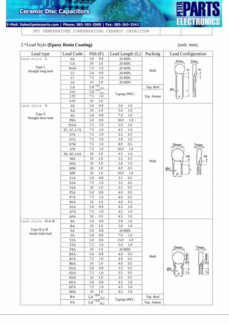
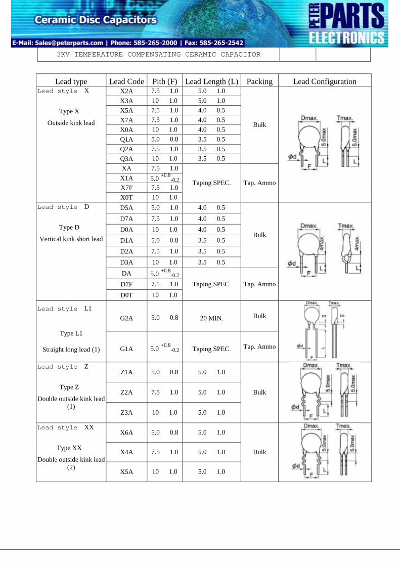
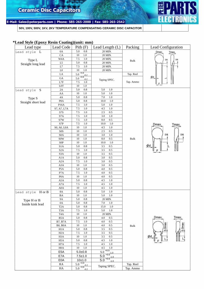
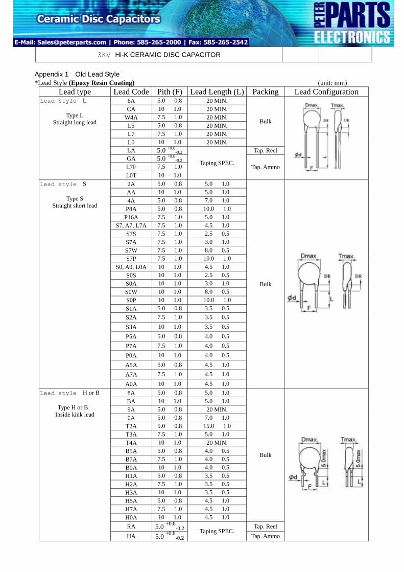
2.*Lead Style (Epoxy Resin Coating) (unit: mm)
Lead type Lead Code Pith (F) Lead Length (L) Packing Lead Configuration 6A 5.0 ± 0.8 20 MIN. CA 10 ± 1.0 20 MIN.
W4A 7.5 ± 1.0 20 MIN. L5 5.0 ± 0.8 20 MIN. L7 7.5 ± 1.0 20 MIN. L0 10 ± 1.0 20 MIN.
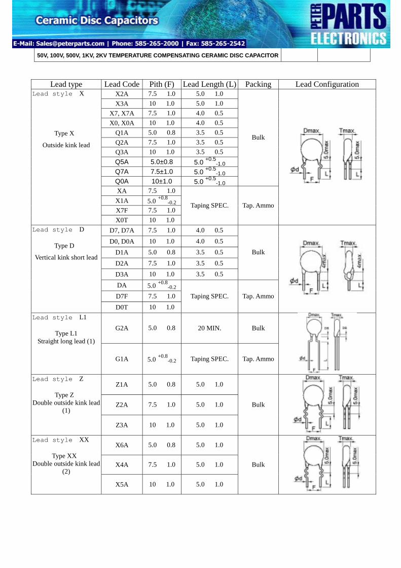
Straight long lead (1) G1A 5.0 +0.8-0.2 Taping SPEC. Tap. Ammo
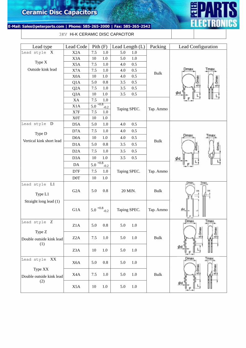
Z1A 5.0 ± 0.8 5.0 ± 1.0
Z2A 7.5 ± 1.0 5.0 ± 1.0
Lead style:Z
Type Z
Double outside kink lead (1)
Z3A 10 ± 1.0 5.0 ± 1.0
Bulk
X6A 5.0 ± 0.8 5.0 ± 1.0
X4A 7.5 ± 1.0 5.0 ± 1.0
Lead style:XX
Type XX
Double outside kink lead (2)
X5A 10 ± 1.0 5.0 ± 1.0
Bulk
POE INTERNATIONAL CORPORATION D08-00-E-06
50V, 100V, 500V, 1KV, 2KV TEMPERATURE COMPENSATING CERAMIC DISC CAPACITOR
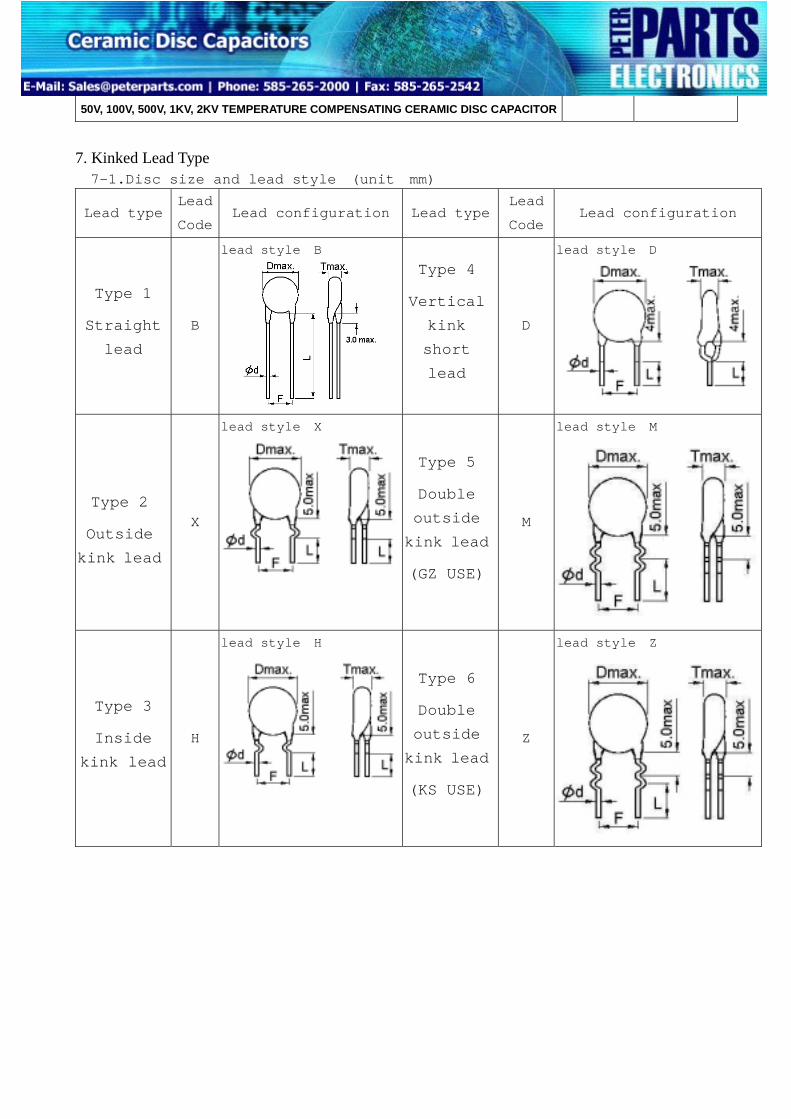
7. Kinked Lead Type 7-1.Disc size and lead style (unit mm)
Lead type Lead
Code Lead configuration Lead type
Lead
CodeLead configuration
Type 1
Straight
lead
B
lead style:B
Type 4
Vertical
kink
short
lead
D
lead style:D
Type 2
Outside
kink lead
X
lead style:X
Type 5
Double
outside
kink lead
(GZ USE)
M
lead style:M
Type 3
Inside
kink lead
H
lead style:H
Type 6
Double
outside
kink lead
(KS USE)
Z
lead style:Z
POE INTERNATIONAL CORPORATION D08-00-E-06
50V, 100V, 500V, 1KV, 2KV TEMPERATURE COMPENSATING CERAMIC DISC CAPACITOR
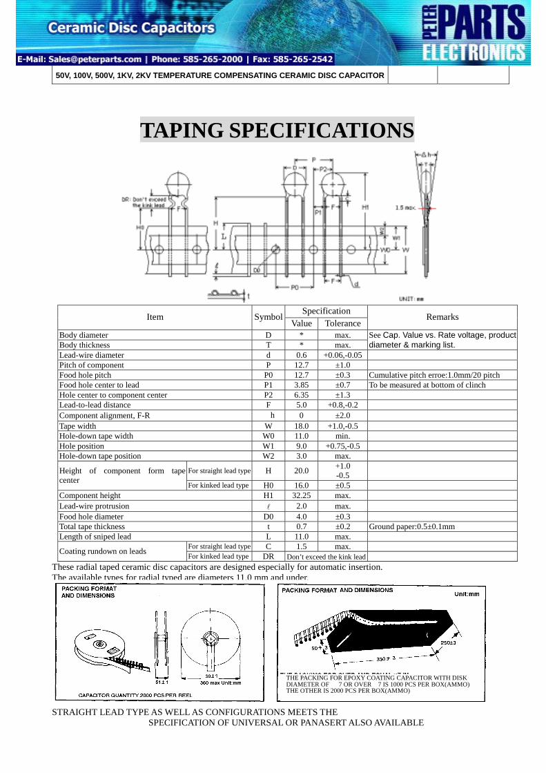
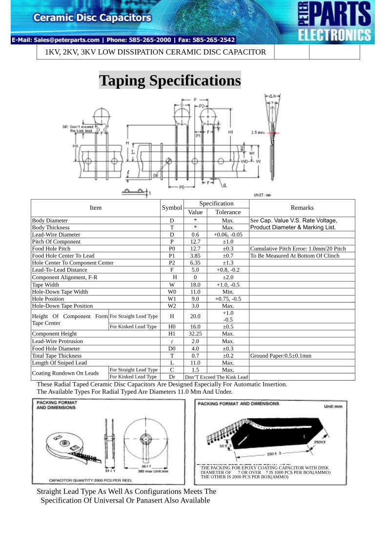
TAPING SPECIFICATIONS
Specification Item SymbolValue Tolerance
Remarks
Body diameter D * max. Body thickness T * max.
See Cap. Value vs. Rate voltage, product diameter & marking list.
Lead-wire diameter d 0.6 +0.06,-0.05 Pitch of component P 12.7 ±1.0 Food hole pitch P0 12.7 ±0.3 Cumulative pitch erroe:1.0mm/20 pitch Food hole center to lead P1 3.85 ±0.7 To be measured at bottom of clinch Hole center to component center P2 6.35 ±1.3 Lead-to-lead distance F 5.0 +0.8,-0.2 Component alignment, F-R △h 0 ±2.0 Tape width W 18.0 +1.0,-0.5 Hole-down tape width W0 11.0 min. Hole position W1 9.0 +0.75,-0.5 Hole-down tape position W2 3.0 max.
For straight lead type H 20.0 +1.0 -0.5 Height of component form tape
center For kinked lead type H0 16.0 ±0.5 Component height H1 32.25 max. Lead-wire protrusion l 2.0 max. Food hole diameter D0 4.0 ±0.3 Total tape thickness t 0.7 ±0.2 Ground paper:0.5±0.1mm Length of sniped lead L 11.0 max.
For straight lead type C 1.5 max. Coating rundown on leads For kinked lead type DR Don’t exceed the kink lead These radial taped ceramic disc capacitors are designed especially for automatic insertion. The available types for radial typed are diameters 11.0 mm and under. STRAIGHT LEAD TYPE AS WELL AS CONFIGURATIONS MEETS THE SPECIFICATION OF UNIVERSAL OR PANASERT ALSO AVAILABLE
THE PACKING FOR EPOXY COATING CAPACITOR WITH DISK DIAMETER OF Φ7 OR OVERΦ7 IS 1000 PCS PER BOX(AMMO) THE OTHER IS 2000 PCS PER BOX(AMMO)
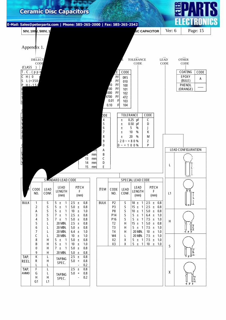
CH U 5 100 J H A DIELECTRIC VOLTAGE DIAMETER CAPACITANCE TOLERANCE LEAD OTHER CODE CODE CODE CODE CODE CODE CODE (CLASSⅠ) T . C . ( p p m / ℃ ) C O D E W.V CODE CAPACITANCE CODE COATING CODE C H ( 0 ± 6 0 ) CH S L (+ 3 5 0 ~ -1 2 0 0 ) SL
EPOXY (BULE) A
P H ( - 1 5 0 ± 6 0 ) PH R H ( - 2 2 0 ± 6 0 ) RH
PHENOL (ORANGE) ------
S H ( - 3 3 0 ± 6 0 ) SH T H ( - 4 7 0 ± 6 0 ) TH U J ( - 7 5 0 ± 1 2 0 ) UJ
Y 5 E ( ± 4 . 7 % ) A 4 mm 4 ± 0.25 pF C Y 5 P ( ± 1 0 % ) B 5 mm 5 ± 0.50 pF D X 7 R ( ± 1 5 % ) X 6 mm 6 ± 5 % J Z 5 U ( + 2 2∼ - 5 6 % ) E 7 mm 7 ± 10 % K Z 5 V ( + 2 2∼ - 8 2 % ) F 8 mm 8 ± 20 % M 9 mm 9 - 2 0 ~ + 8 0 % Z (CLASSⅢ) 10 mm 0 0 ~ + 1 0 0 % P
T.C. (△C%) C O D E 11 mm A LEAD CONFIGURATION Y5V ( + 2 2 ~ - 8 2 % ) FY 12 mm B Y5T ( + 2 2 ~ - 3 3 % ) D 13 mm C Y5R ( ± 1 5 % ) RY 14 mm D 15 mm E
L
STANDARD LEAD CODE SPECIAL LEAD CODE
ITEM CODE NO.
LEAD CONF.
LEAD LENGTH
(mm)
PITCH F
(mm)
ITEM CODE NO.
LEAD CONF.
LEAD LENGTH
(mm)
PITCH F
(mm)
1 S 5 ± 1 2.5 ± 0.8 BULK P2 S 18 ± 1 2.5 ± 0.8 2 S 5 ± 1 5.0 ± 0.8 P3 S 15 ± 1 2.5 ± 0.8
L1
A S 5 ± 1 10 ± 1.0 P8 S 10 ± 1 5.0 ± 0.8 3 S 7 ± 1 2.5 ± 0.8 P14 S 5 ± 1 6.4 ± 1.0 4 S 7 ± 1 5.0 ± 0.8 P16 S 5 ± 1 7.5 ± 1.0 5 L 20 MIN. 2.5 ± 0.8 T2 H 15 ± 1 5.0 ± 0.8 6 L 20 MIN. 5.0 ± 0.8 T3 H 5 ± 1 7.5 ± 1.0 7 L 20 MIN. 6.4 ± 1.0 T4 H 20 MIN. 10 ± 1.0
H
C L 20 MIN. 10 ± 1.0
W4 L 20 MIN. 7.5 ± 1.0
8 H 5 ± 1 5.0 ± 0.8 X2 X 5 ± 1 7.5 ± 1.0 B H 5 ± 1 10 ± 1.0 X3 X 5 ± 1 10 ± 1.0
0 H 7 ± 1 5.0 ± 0.8
BULK
9 H 20 MIN. 5.0 ± 0.8 K L 2.5 ± 0.8
S
R H 5.0 + 0.8 TAP.
REEL L L
TAPING SPEC. - 0.2
F L 2.5 ± 0.8 G L 5.0 + 0.8 H H - 0.2
TAP. AMMO
G1 L1
TAPING SPEC.
X
POE INTERNATIONAL CORPORATION D08-00-E-06
50V, 100V, 500V, 1KV, 2KV TEMPERATURE COMPENSATING CERAMIC DISC CAPACITOR
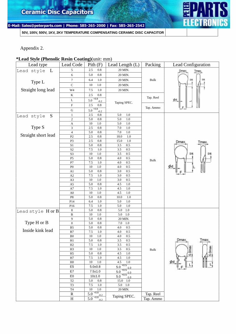
Appendix 2.
*Lead Style (Phenolic Resin Coating)(unit: mm) Lead type Lead Code Pith (F) Lead Length (L) Packing Lead Configuration
5 2.5 ± 0.8 20 MIN. 6 5.0 ± 0.8 20 MIN. 7 6.4 ± 1.0 20 MIN. C 10 ± 1.0 20 MIN.
Y 5 E ( ± 4 . 7 % ) A 4 mm 4 ± 0.25 pF C Y 5 P ( ± 1 0 % ) B 5 mm 5 ± 0.50 pF D X 7 R ( ± 1 5 % ) X 6 mm 6 ± 5 % J Z 5 U ( + 2 2∼ - 5 6 % ) E 7 mm 7 ± 10 % K Z 5 V ( + 2 2∼ - 8 2 % ) F 8 mm 8 ± 20 % M 9 mm 9 - 2 0 ~ + 8 0 % Z (CLASSⅢ) 10 mm 0 0 ~ + 1 0 0 % P
T.C. (△C%) C O D E 11 mm A LEAD CONFIGURATION Y5V ( + 2 2 ~ - 8 2 % ) FY 12 mm B Y5T ( + 2 2 ~ - 3 3 % ) D 13 mm C Y5R ( ± 1 5 % ) RY 14 mm D 15 mm E
L
STANDARD LEAD CODE SPECIAL LEAD CODE
ITEM CODE NO.
LEAD CONF.
LEAD LENGTH
(mm)
PITCH F
(mm)
ITEM CODE NO.
LEAD CONF.
LEAD LENGTH
(mm)
PITCH F
(mm)
1 S 5 ± 1 2.5 ± 0.8 BULK P2 S 18 ± 1 2.5 ± 0.8 2 S 5 ± 1 5.0 ± 0.8 P3 S 15 ± 1 2.5 ± 0.8
L1
A S 5 ± 1 10 ± 1.0 P8 S 10 ± 1 5.0 ± 0.8 3 S 7 ± 1 2.5 ± 0.8 P14 S 5 ± 1 6.4 ± 1.0 4 S 7 ± 1 5.0 ± 0.8 P16 S 5 ± 1 7.5 ± 1.0 5 L 20 MIN. 2.5 ± 0.8 T2 H 15 ± 1 5.0 ± 0.8 6 L 20 MIN. 5.0 ± 0.8 T3 H 5 ± 1 7.5 ± 1.0 7 L 20 MIN. 6.4 ± 1.0 T4 H 20 MIN. 10 ± 1.0
H
C L 20 MIN. 10 ± 1.0
W4 L 20 MIN. 7.5 ± 1.0
8 H 5 ± 1 5.0 ± 0.8 X2 X 5 ± 1 7.5 ± 1.0 B H 5 ± 1 10 ± 1.0 X3 X 5 ± 1 10 ± 1.0 0 H 7 ± 1 5.0 ± 0.8
BULK
9 H 20 MIN. 5.0 ± 0.8 K L 2.5 ± 0.8
S
R H 5.0 + 0.8 TAP.
REEL L L
TAPING SPEC. - 0.2
F L 2.5 ± 0.8 G L 5.0 + 0.8 H H - 0.2
TAP. AMMO
G1 L1
TAPING SPEC.
X
POE INTERNATIONAL CORPORATION D13-00-E-05
3KV Hi-K CERAMIC DISC CAPACITOR 7.Kinked Lead Type 7-1.Disc size and lead style:(unit:mm)
Lead type Lead Code Lead configuration Lead type Lead
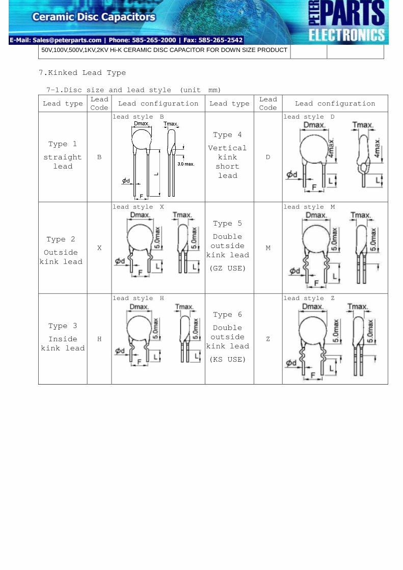
50V,100V,500V,1KV,2KV Hi-K CERAMIC DISC CAPACITOR FOR DOWN SIZE PRODUCT
7.Kinked Lead Type
7-1.Disc size and lead style (unit mm)
Lead type Lead Code Lead configuration Lead type Lead
Code Lead configuration
Type 1
straight lead
B
lead style:B
Type 4
Vertical kink short lead
D
lead style:D
Type 2
Outside kink lead
X
lead style:X
Type 5
Double outside kink lead
(GZ USE)
M
lead style:M
Type 3
Inside kink lead
H
lead style:H
Type 6
Double outside kink lead
(KS USE)
Z
lead style:Z
POE INTERNATIONAL CORPORATION D15-00-E-05
50V,100V,500V,1KV,2KV Hi-K CERAMIC DISC CAPACITOR FOR DOWN SIZE PRODUCT
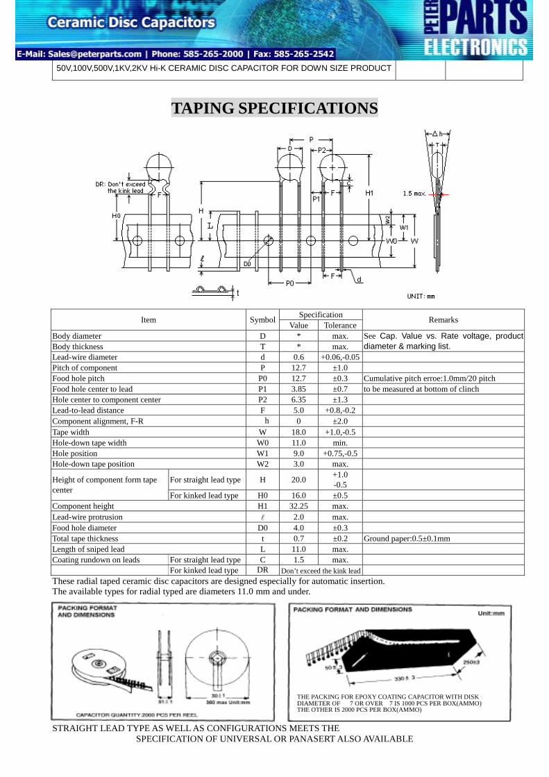
TAPING SPECIFICATIONS
Body diamBody thickLead-wire Pitch of coFood hole Food hole Hole centeLead-to-leComponenTape widthHole-downHole positiHole-down
Height of ccenter
ComponenLead-wire Food hole Total tape Length of Coating ru These radThe avail STRAIGH
Specification Item SymbolValue Tolerance
Remarks
eter D * max. ness T * max.
See Cap. Value vs. Rate voltage, product diameter & marking list.
diameter d 0.6 +0.06,-0.05 mponent P 12.7 ±1.0 pitch P0 12.7 ±0.3 Cumulative pitch erroe:1.0mm/20 pitch center to lead P1 3.85 ±0.7 to be measured at bottom of clinch r to component center P2 6.35 ±1.3 ad distance F 5.0 +0.8,-0.2 t alignment, F-R △h 0 ±2.0 W 18.0 +1.0,-0.5 tape width W0 11.0 min. on W1 9.0 +0.75,-0.5 tape position W2 3.0 max.
For straight lead type H 20.0 +1.0 -0.5 omponent form tape
For kinked lead type H0 16.0 ±0.5 t height H1 32.25 max. protrusion l 2.0 max. diameter D0 4.0 ±0.3 thickness t 0.7 ±0.2 Ground paper:0.5±0.1mm sniped lead L 11.0 max. ndown on leads For straight lead type C 1.5 max.
For kinked lead type DR Don’t exceed the kink lead ial taped ceramic disc capacitors are designed especially for automatic insertion. able types for radial typed are diameters 11.0 mm and under.
T LEAD TYPE AS WELL AS CONFIGURATIONS MEETS THE
THE PACKING FOR EPOXY COATING CAPACITOR WITH DISK DIAMETER OF Φ7 OR OVERΦ7 IS 1000 PCS PER BOX(AMMO) THE OTHER IS 2000 PCS PER BOX(AMMO)
SPECIFICATION OF UNIVERSAL OR PANASERT ALSO AVAILABLE
POE INTERNATIONAL CORPORATION D15-00-E-05
50V,100V,500V,1KV,2KV Hi-K CERAMIC DISC CAPACITOR FOR DOWN SIZE PRODUCT
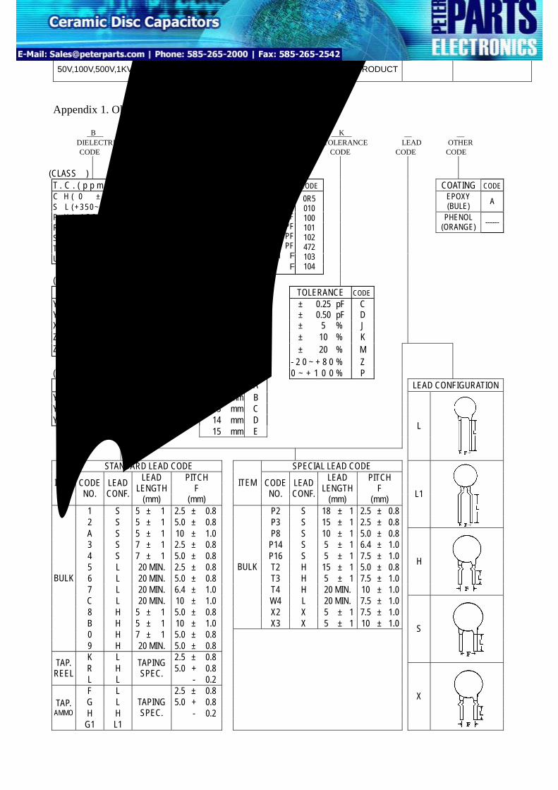
Appendix 1. Old Part Number
B M2 8 102 K H A DIELECTRIC VOLTAGE DIAMETER CAPACITANCE TOLERANCE LEAD OTHER CODE CODE CODE CODE CODE CODE CODE
(CLASSⅠ)
T . C . ( p p m /℃ ) CODE W.V CODE CAPACITANCE CODE COATING CODE C H ( 0 ± 6 0 ) CH S L (+ 3 5 0 ~ -1 2 0 0 ) SL
EPOXY (BULE) A
P H ( - 1 5 0 ± 6 0 ) PH R H ( - 2 2 0 ± 6 0 ) RH
PHENOL (ORANGE) ------
S H ( - 3 3 0 ± 6 0 ) SH T H ( - 4 7 0 ± 6 0 ) TH U J ( - 7 5 0 ± 1 2 0 ) UJ
Y5E ( ± 4 . 7 % ) A 4 mm 4 ± 0.25 pF C Y5P ( ± 1 0 % ) B 5 mm 5 ± 0.50 pF D X7R ( ± 1 5 % ) X 6 mm 6 ± 5 % J Z5U (+22∼ -56%) E 7 mm 7 ± 10 % K Z5V (+22∼ -82%) F 8 mm 8 ± 20 % M 9 mm 9 - 2 0 ~ + 8 0 % Z (CLASSⅢ) 10 mm 0 0 ~ + 1 0 0 % P
T.C. (△C%) CODE 11 mm A LEAD CONFIGURATION Y5V ( + 2 2 ~ - 8 2 % ) FY 12 mm B Y5T ( + 2 2 ~ - 3 3 % ) D 13 mm C Y5R ( ± 1 5 % ) RY 14 mm D 15 mm E
L
STANDARD LEAD CODE SPECIAL LEAD CODE
ITEM CODE NO.
LEAD CONF.
LEAD LENGTH
(mm)
PITCH F
(mm)
ITEM CODE NO.
LEAD CONF.
LEAD LENGTH
(mm)
PITCH F
(mm) 1 S 5 ± 1 2.5 ± 0.8 P2 S 18 ± 1 2.5 ± 0.8 2 S 5 ± 1 5.0 ± 0.8 P3 S 15 ± 1 2.5 ± 0.8
L1
A S 5 ± 1 10 ± 1.0 P8 S 10 ± 1 5.0 ± 0.8 3 S 7 ± 1 2.5 ± 0.8 P14 S 5 ± 1 6.4 ± 1.0 4 S 7 ± 1 5.0 ± 0.8 P16 S 5 ± 1 7.5 ± 1.0 5 L 20 MIN. 2.5 ± 0.8 T2 H 15 ± 1 5.0 ± 0.8 6 L 20 MIN. 5.0 ± 0.8 T3 H 5 ± 1 7.5 ± 1.0 7 L 20 MIN. 6.4 ± 1.0 T4 H 20 MIN. 10 ± 1.0
H
C L 20 MIN. 10 ± 1.0
W4 L 20 MIN. 7.5 ± 1.0
8 H 5 ± 1 5.0 ± 0.8 X2 X 5 ± 1 7.5 ± 1.0 B H 5 ± 1 10 ± 1.0
BULK
X3 X 5 ± 1 10 ± 1.0
0 H 7 ± 1 5.0 ± 0.8
BULK
9 H 20 MIN. 5.0 ± 0.8 K L 2.5 ± 0.8
S
R H 5.0 + 0.8 TAP. REEL L L
TAPING SPEC. - 0.2
F L 2.5 ± 0.8 G L 5.0 + 0.8 H H - 0.2
TAP. AMMO
G1 L1
TAPING SPEC.
X
POE INTERNATIONAL CORPORATION D15-00-E-05
50V,100V,500V,1KV,2KV Hi-K CERAMIC DISC CAPACITOR FOR DOWN SIZE PRODUCT
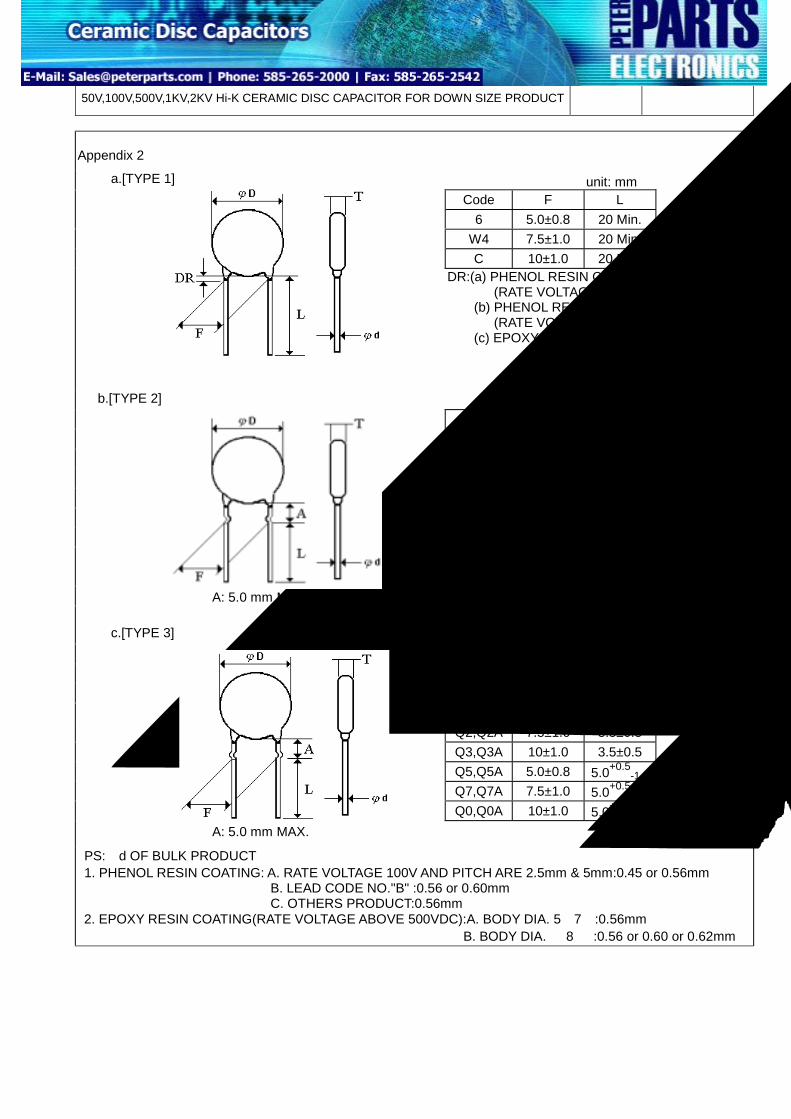
Appendix 2
unit: mm Code F L
6 5.0±0.8 20 Min. W4 7.5±1.0 20 Min. C 10±1.0 20 Min.
a.[TYPE 1]
DR:(a) PHENOL RESIN COATING (RATE VOLTAGE 50V,100V): 1.5mm MAX (b) PHENOL RESIN COATING (RATE VOLTAGE 500V,1KV,2KV):2.0 MAX (c) EPOXY RESIN COATING: 3.0 mm MAX
PS:φd OF BULK PRODUCT 1. PHENOL RESIN COATING: A. RATE VOLTAGE 100V AND PITCH ARE 2.5mm & 5mm:0.45 or 0.56mm B. LEAD CODE NO."B" :0.56 or 0.60mm C. OTHERS PRODUCT:0.56mm 2. EPOXY RESIN COATING(RATE VOLTAGE ABOVE 500VDC):A. BODY DIA. 5∼7φ:0.56mm B. BODY DIA. ≧8φ :0.56 or 0.60 or 0.62mm
POE INTERNATIONAL CORPORATION D11-00-E-05
X7R HI-K CERAMIC DISC CAPACITOR
7. Kinked Lead Type 7-1.Disc size and lead style (unit mm)
Lead type Lead Code Lead configuration Lead type Lead
Code Lead configuration
Type 1
Straight lead
B
lead style:B
Type 4
Vertical kink short lead
D
lead style:D
Type 2
Outside kink lead
X
lead style:X
Type 5
Double outside kink lead
(GZ USE)
M
lead style:M
Type 3
Inside kink lead
H
lead style:H
Type 6
Double outside kink lead
(KS USE)
Z
lead style:Z
POE INTERNATIONAL CORPORATION D11-00-E-05
X7R HI-K CERAMIC DISC CAPACITOR * Lead spacing :F=5.0 +0.8
-0.2 (mm)
TAPING SPECIFICATIONS
Body diameter Body thickness Lead-wire diameter Pitch of component Food hole pitch Food hole center to Hole center to compLead-to-lead distancComponent alignmeTape width Hole-down tape widHole position Hole-down tape pos
Height of componencenter
Component height Lead-wire protrusioFood hole diameter Total tape thicknessLength of sniped leaCoating rundown on
These radial tapedThe available type
STRAIGHT LEUNIVERSAL O
Specification Item SymbolValue Tolerance
Remarks
D * max. T * max.
See Cap. Value v.s. Rate voltage, product diameter & marking list.
d 0.6 +0.06,-0.05 P 12.7 ±1.0
P0 12.7 ±0.3 Cumulative pitch erroe:1.0mm/20 pitch lead P1 3.85 ±0.7 To be measured at bottom of clinch onent center P2 6.35 ±1.3 e F 5.0 +0.8,-0.2 nt, F-R △h 0 ±2.0
W 18.0 +1.0,-0.5 th W0 11.0 min.
W1 9.0 +0.75,-0.5 ition W2 3.0 max.
For straight lead type H 20.0 +1.0 -0.5 t form tape
For kinked lead type H0 16.0 ±0.5 H1 32.25 max.
n l 2.0 max. D0 4.0 ±0.3
t 0.7 ±0.2 Ground paper:0.5±0.1mm d L 11.0 max.
For straight lead type C 1.5 max. leads For kinked lead type DR Don’t exceed the kink lead ceramic disc capacitors are designed especially for automatic insertion. s for radial typed are diameters 11.0 mm and under.
AD TYPE AS WELL AS CONFIGURATIONS MEETS THE SPECIFICATION OF R PANASERT ALSO AVAILABLE
THE PACKING FOR EPOXY COATING CAPACITOR WITH DISK DIAMETER OF Φ7 OR OVERΦ7 IS 1000 PCS PER BOX(AMMO) THE OTHER IS 2000 PCS PER BOX(AMMO)
S H ( - 3 3 0 ± 6 0 ) SH T H ( - 4 7 0 ± 6 0 ) TH U J ( - 7 5 0 ± 1 2 0 ) UJ
16 VDC 25 VDC 50 VDC
100 VDC 500 VDC 1 KVDC 2 KVDC 3 KVDC
B T U A C M M2 M3
0.5 PF 1 PF
10 PF 100 PF
1000 PF 4700 PF
0.01μF 0.10 μF
0R5 010 100 101 102 472 103 104
(CALSSⅡ) T.C. (△C%) C O D E D I A M E T E R C O D E TOLERANCE CODE
Y 5 E ( ± 4 . 7 % ) A 4 mm 4 ± 0.25 pF C Y 5 P ( ± 1 0 % ) B 5 mm 5 ± 0.50 pF D X 7 R ( ± 1 5 % ) X 6 mm 6 ± 5 % J Z 5 U ( + 2 2∼ - 5 6 % ) E 7 mm 7 ± 10 % K Z 5 V ( + 2 2∼ - 8 2 % ) F 8 mm 8 ± 20 % M 9 mm 9 - 2 0 ~ + 8 0 % Z (CLASSⅢ) 10 mm 0 0 ~ + 1 0 0 % P
T.C. (△C%) C O D E 11 mm A LEAD CONFIGURATION Y5V ( + 2 2 ~ - 8 2 % ) FY 12 mm B Y5T ( + 2 2 ~ - 3 3 % ) D 13 mm C Y5R ( ± 1 5 % ) RY 14 mm D 15 mm E
L
STANDARD LEAD CODE SPECIAL LEAD CODE
ITEM CODE NO.
LEAD CONF.
LEAD LENGTH
(mm)
PITCH F
(mm)
ITEM CODE NO.
LEAD CONF.
LEAD LENGTH
(mm)
PITCH F
(mm)
1 S 5 ± 1 2.5 ± 0.8 BULK P2 S 18 ± 1 2.5 ± 0.8 2 S 5 ± 1 5.0 ± 0.8 P3 S 15 ± 1 2.5 ± 0.8
L1
A S 5 ± 1 10 ± 1.0 P8 S 10 ± 1 5.0 ± 0.8 3 S 7 ± 1 2.5 ± 0.8 P14 S 5 ± 1 6.4 ± 1.0 4 S 7 ± 1 5.0 ± 0.8 P16 S 5 ± 1 7.5 ± 1.0 5 L 25 MIN. 2.5 ± 0.8 T2 H 15 ± 1 5.0 ± 0.8 6 L 25 MIN. 5.0 ± 0.8 T3 H 5 ± 1 7.5 ± 1.0 7 L 25 MIN. 6.4 ± 1.0 T4 H 25 MIN. 10 ± 1.0
H
C L 25 MIN. 10 ± 1.0
W4 L 25 MIN. 7.5 ± 1.0
8 H 5 ± 1 5.0 ± 0.8 X2 X 5 ± 1 7.5 ± 1.0 B H 5 ± 1 10 ± 1.0 X3 X 5 ± 1 10 ± 1.0
0 H 7 ± 1 5.0 ± 0.8
BULK
9 H 25 MIN. 5.0 ± 0.8 K L 2.5 ± 0.8
S
R H 5.0 + 0.8 TAP.
REEL L L
TAPING SPEC. - 0.2
F L 2.5 ± 0.8 G L 5.0 + 0.8 H H - 0.2
TAP. AMMO
G1 L1
TAPING SPEC.
X
POE INTERNATIONAL CORPORATION D11-00-E-05
HI-K CERAMIC DISC CAPACITOR
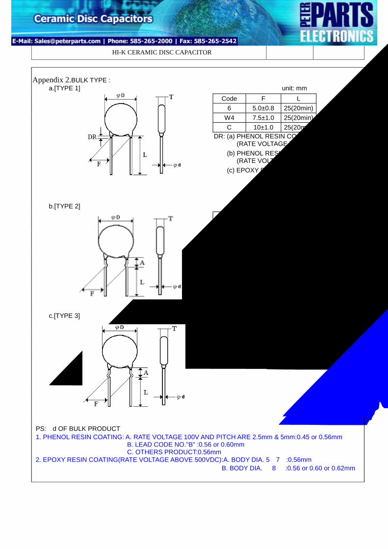
Appendix 2.BULK TYPE : unit: mm
Code F L 6 5.0±0.8 25(20min)
W4 7.5±1.0 25(20min) C 10±1.0 25(20min)
a.[TYPE 1]
DR: (a) PHENOL RESIN COATING (RATE VOLTAGE 50V,100V): 1.5mm MAX (b) PHENOL RESIN COATING (RATE VOLTAGE 500V,1KV,2KV):2.0 MAX (c) EPOXY RESIN COATING: 3.0 mm MAX
unit: mm Code F L
8 5.0±0.8 5±1 T3 7.5±1.0 5±1 B 10±1.0 5±1
b.[TYPE 2]
A: 5.0 mm MAX.
unit: mm Code F L
X2 7.5±1.0 5±1 X3 10±1.0 5±1
c.[TYPE 3]
A: 5.0 mm MAX.
PS:φd OF BULK PRODUCT 1. PHENOL RESIN COATING: A. RATE VOLTAGE 100V AND PITCH ARE 2.5mm & 5mm:0.45 or 0.56mm B. LEAD CODE NO."B" :0.56 or 0.60mm C. OTHERS PRODUCT:0.56mm 2. EPOXY RESIN COATING(RATE VOLTAGE ABOVE 500VDC):A. BODY DIA. 5∼7φ:0.56mm B. BODY DIA. ≧8φ :0.56 or 0.60 or 0.62mm
POE INTERNATIONAL CORPORATION D16-00-E-04
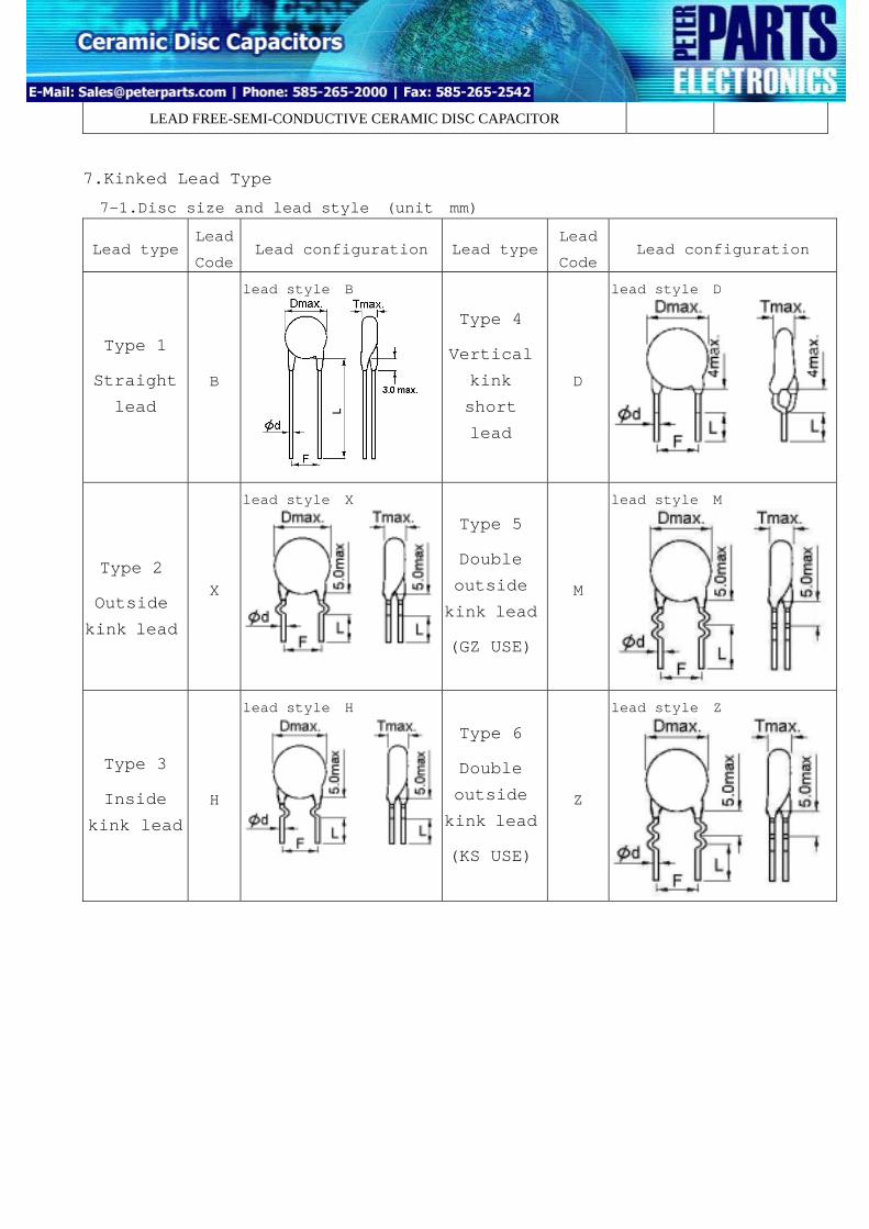
LEAD FREE-SEMI-CONDUCTIVE CERAMIC DISC CAPACITOR
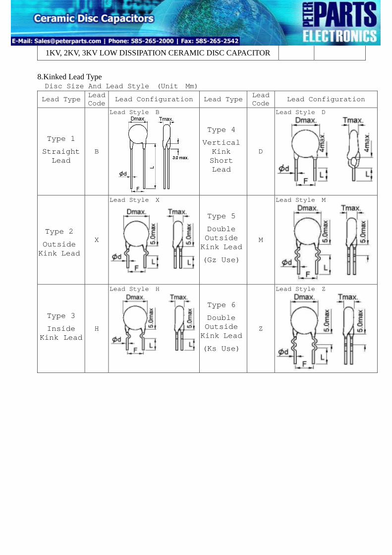
7.Kinked Lead Type
7-1.Disc size and lead style (unit mm)
Lead type Lead
Code Lead configuration Lead type
Lead
CodeLead configuration
Type 1
Straight
lead
B
lead style:B
Type 4
Vertical
kink
short
lead
D
lead style:D
Type 2
Outside
kink lead
X
lead style:X
Type 5
Double
outside
kink lead
(GZ USE)
M
lead style:M
Type 3
Inside
kink lead
H
lead style:H
Type 6
Double
outside
kink lead
(KS USE)
Z
lead style:Z
POE INTERNATIONAL CORPORATION D16-00-E-04
LEAD FREE-SEMI-CONDUCTIVE CERAMIC DISC CAPACITOR
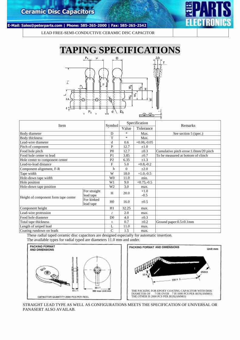
TAPING SPECIFICATIONS
Specification Item Symbol
Value ToleranceRemarks
Body diameter D * Max. See section 5 (spec.) Body thickness T * Max. Lead-wire diameter d 0.6 +0.06,-0.05 Pitch of component P 12.7 ±1.0 Food hole pitch P0 12.7 ±0.3 Cumulative pitch erroe:1.0mm/20 pitch Food hole center to lead P1 3.85 ±0.7 To be measured at bottom of clinch Hole center to component center P2 6.35 ±1.3 Lead-to-lead distance F 5.0 +0.8,-0.2 Component alignment, F-R △h 0 ±2.0 Tape width W 18.0 +1.0,-0.5 Hole-down tape width W0 11.0 min. Hole position W1 9.0 +0.75,-0.5 Hole-down tape position W2 3.0 max.
For straight lead tape H 20.0 +1.0
-0.5 Height of component form tape center For kinked
lead tape H0 16.0 ±0.5
Component height H1 32.25 max. Lead-wire protrusion l 2.0 max. Food hole diameter D0 4.0 ±0.3 Total tape thickness t 0.7 ±0.2 Ground paper:0.5±0.1mm Length of sniped lead L 11.0 max. Coating rundown on leads C 1.5 max.
These radial taped ceramic disc capacitors are designed especially for automatic insertion. The available types for radial typed are diameters 11.0 mm and under.
STRAIGHT LEAD TYPE AS WELL AS CONFIGURATIONS MEETS THE SPECIFICATION OF UNIVERSAL OR PANASERT ALSO AVAILAB.
THE PACKING FOR EPOXY COATING CAPACITOR WITH DISK DIAMETER OF Φ7 OR OVERΦ7 IS 1000 PCS PER BOX(AMMO) THE OTHER IS 2000 PCS PER BOX(AMMO)
POE INTERNATIONAL CORPORATION D16-00-E-04
LEAD FREE-SEMI-CONDUCTIVE CERAMIC DISC CAPACITOR
Appendix 1. Old Part Number FY U 6 104 Z H DIELECTRIC VOLTAGE DIAMETER CAPACITANCE TOLERANCE LEAD CODE CODE CODE CODE CODE CODE
(CLASSⅢ)
T.C. (△C%) CODE W.V CODE CAPACITANCE CODE
Y5V(+22~-82%) FY
16 VDC 25 VDC 50 VDC
B T U
0. 010μF 0.047μF 0.100μF
103 473 104
DIAMETER CODE TOLERANCE CODE
±20% -20~+80% 0~+100%
M Z P
5 mm 6 mm 7 mm 8 mm 10 mm
5 6 7 8 0
LEAD CONFIGURATION
L
STANDARD LEAD CODE SPECIAL LEAD CODE
ITEM CODE NO.
LEAD CONF.
LEAD LENGTH
(mm)
PITCH F
(mm)
ITEM CODE NO.
LEAD CONF.
LEAD LENGTH
(mm)
PITCH F
(mm)
1 S 5 ± 1 2.5 ± 0.8 BULK P2 S 18 ± 1 2.5 ± 0.8 2 S 5 ± 1 5.0 ± 0.8 P3 S 15 ± 1 2.5 ± 0.8
L1
A S 5 ± 1 10 ± 1.0 P8 S 10 ± 1 5.0 ± 0.8 3 S 7 ± 1 2.5 ± 0.8 P14 S 5 ± 1 6.4 ± 1.0 4 S 7 ± 1 5.0 ± 0.8 P16 S 5 ± 1 7.5 ± 1.0 5 L 20 MIN. 2.5 ± 0.8 T2 H 15 ± 1 5.0 ± 0.8 6 L 20 MIN. 5.0 ± 0.8 T3 H 5 ± 1 7.5 ± 1.0 7 L 20 MIN. 6.4 ± 1.0 T4 H 20 MIN. 10 ± 1.0
H
C L 20 MIN. 10 ± 1.0
W4 L 20 MIN. 7.5 ± 1.0
8 H 5 ± 1 5.0 ± 0.8 X2 X 5 ± 1 7.5 ± 1.0 B H 5 ± 1 10 ± 1.0 X3 X 5 ± 1 10 ± 1.0
0 H 7 ± 1 5.0 ± 0.8
BULK
9 H 25 MIN. 5.0 ± 0.8 K L 2.5 ± 0.8
S
R H 5.0 + 0.8 TAP. REEL L L
TAPING SPEC. - 0.2
F L 2.5 ± 0.8 G L H H
TAP. AMMO
G1 X1
L1 X
TAPING SPEC. 5.0 +
- 0.8 0.2
CUSTOMER SPECIFICATION ANY POSSIBLE PHYSICAL CONFIGURATION CAN BE
SPECIFIED, PAN OVERSEAS WILLBUILD THE PARTS TO
MEET YOUR REQUIREMENTS
X
POE INTERNATIONAL CORPORATION D16-00-E-04
LEAD FREE-SEMI-CONDUCTIVE CERAMIC DISC CAPACITOR
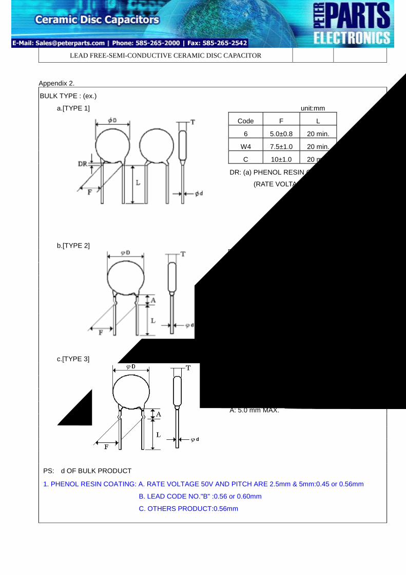
Appendix 2.
BULK TYPE : (ex.)
unit:mm
Code F L
6 5.0±0.8 20 min.
W4 7.5±1.0 20 min.
C 10±1.0 20 min.
a.[TYPE 1]
DR: (a) PHENOL RESIN COATING
(RATE VOLTAGE 50V,100V): 1.5mm MAX
unit:mm
Code F L
8 5.0±0.8 5±1
T3 7.5±1.0 5±1
B 10±1.0 5±1
b.[TYPE 2]
A: 5.0 mm MAX.
unit:mm
Code F L
X2 7.5±1.0 5±1
X3 10±1.0 5±1
c.[TYPE 3]
A: 5.0 mm MAX.
PS:φd OF BULK PRODUCT
1. PHENOL RESIN COATING: A. RATE VOLTAGE 50V AND PITCH ARE 2.5mm & 5mm:0.45 or 0.56mm
Body DiamBody ThicLead-WirePitch Of CFood HoleFood HoleHole CenteLead-To-LComponenTape WidthHole-DowHole PositHole-Dow
Height OTape Cente
ComponenLead-WireFood HoleTotal TapeLength Of
Coating Ru
These RThe Ava
Straigh Speci
Specification Item SymbolValue Tolerance
Remarks
eter D * Max. kness T * Max.
See Cap. Value V.S. Rate Voltage, Product Diameter & Marking List.
Diameter D 0.6 +0.06, -0.05 omponent P 12.7 ±1.0 Pitch P0 12.7 ±0.3 Cumulative Pitch Erroe: 1.0mm/20 Pitch Center To Lead P1 3.85 ±0.7 To Be Measured At Bottom Of Clinch r To Component Center P2 6.35 ±1.3 ead Distance F 5.0 +0.8, -0.2 t Alignment, F-R △H 0 ±2.0 W 18.0 +1.0, -0.5
n Tape Width W0 11.0 Min. ion W1 9.0 +0.75, -0.5 n Tape Position W2 3.0 Max.
For Straight Lead Type H 20.0 +1.0 -0.5 f Component Form
r For Kinked Lead Type H0 16.0 ±0.5 t Height H1 32.25 Max. Protrusion l 2.0 Max. Diameter D0 4.0 ±0.3 Thickness T 0.7 ±0.2 Ground Paper:0.5±0.1mm Sniped Lead L 11.0 Max.
For Straight Lead Type C 1.5 Max. ndown On Leads For Kinked Lead Type Dr Don’T Exceed The Kink Lead adial Taped Ceramic Disc Capacitors Are Designed Especially For Automatic Insertion. ilable Types For Radial Typed Are Diameters 11.0 Mm And Under.
t Lead Type As Well As Configurations Meets The fication Of Universal Or Panasert Also Available
THE PACKING FOR EPOXY COATING CAPACITOR WITH DISK DIAMETER OF Φ7 OR OVERΦ7 IS 1000 PCS PER BOX(AMMO) THE OTHER IS 2000 PCS PER BOX(AMMO)
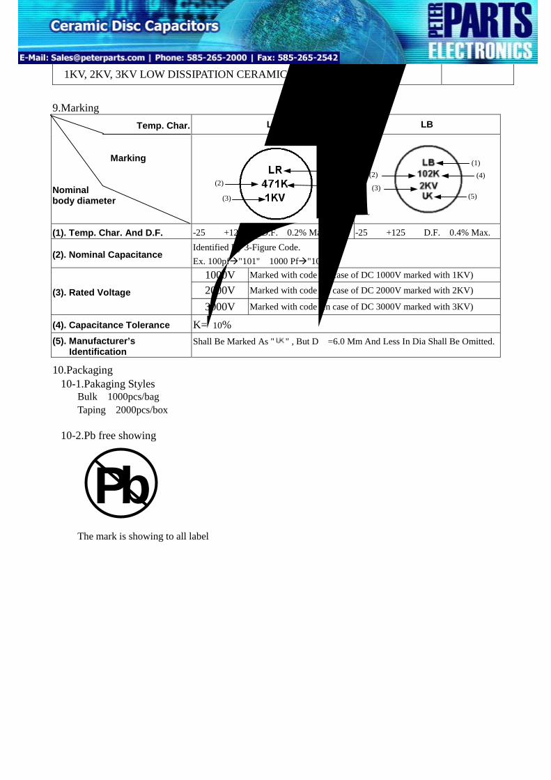
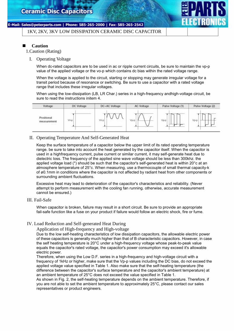
I. Operating Voltage When dc-rated capacitors are to be used in ac or ripple current circuits, be sure to maintain the vp-p value of the applied voltage or the vo-p which contains dc bias within the rated voltage range.
When the voltage is applied to the circuit, starting or stopping may generate irregular voltage for a transit period because of resonance or switching. Be sure to use a capacitor with a rated voltage range that includes these irregular voltages.
When using the low-dissipation (LB, LR Char.) series in a high-frequency andhigh-voltage circuit, be sure to read the instructions initem 4.
II. Operating Temperature And Self-Generated Heat Keep the surface temperature of a capacitor below the upper limit of its rated operating temperature range. be sure to take into account the heat generated by the capacitor itself. When the capacitor is used in a highfrequency current, pulse current or similar current, it may self-generate heat due to dielectric loss. The frequency of the applied sine wave voltage should be less than 300khz. the applied voltage load (*) should be such that the capacitor's self-generated heat is within 20°c at an atmosphere temperature of 25°c. When measuring, use a thermocouple of small thermal capacity-k of ø0.1mm in conditions where the capacitor is not affected by radiant heat from other components or surrounding ambient fluctuations.
Excessive heat may lead to deterioration of the capacitor's characteristics and reliability. (Never attempt to perform measurement with the cooling fan running. otherwise, accurate measurement cannot be ensured.)
III. Fail-Safe When capacitor is broken, failure may result in a short circuit. Be sure to provide an appropriate fail-safe function like a fuse on your product if failure would follow an electric shock, fire or fume.
IV. Load Reduction and Self-generated Heat During Application of High-frequency and High-voltage Due to the low self-heating characteristics of low dissipation capacitors, the allowable electric power of these capacitors is generally much higher than that of B characteristic capacitors. However, in case the self heating temperature is 20°C under a high-frequency voltage whose peak-to-peak value equals the capacitor's rated voltage, the capacitor's power consumption may exceed it's allowable electric power. Therefore, when using the Low D.F. series in a high-frequency and high-voltage circuit with a frequency of 1kHz or higher, make sure that the Vp-p values including the DC bias, do not exceed the applied voltage value specified in Table 1. Also make sure that the self-heating temperature (the difference between the capacitor's surface temperature and the capacitor's ambient temperature) at an ambient temperature of 25°C does not exceed the value specified in Table 1. As shown in Fig. 2, the self-heating temperature depends on the ambient temperature. Therefore, if you are not able to set the ambient temperature to approximately 25°C, please contact our sales representatives or product engineers.
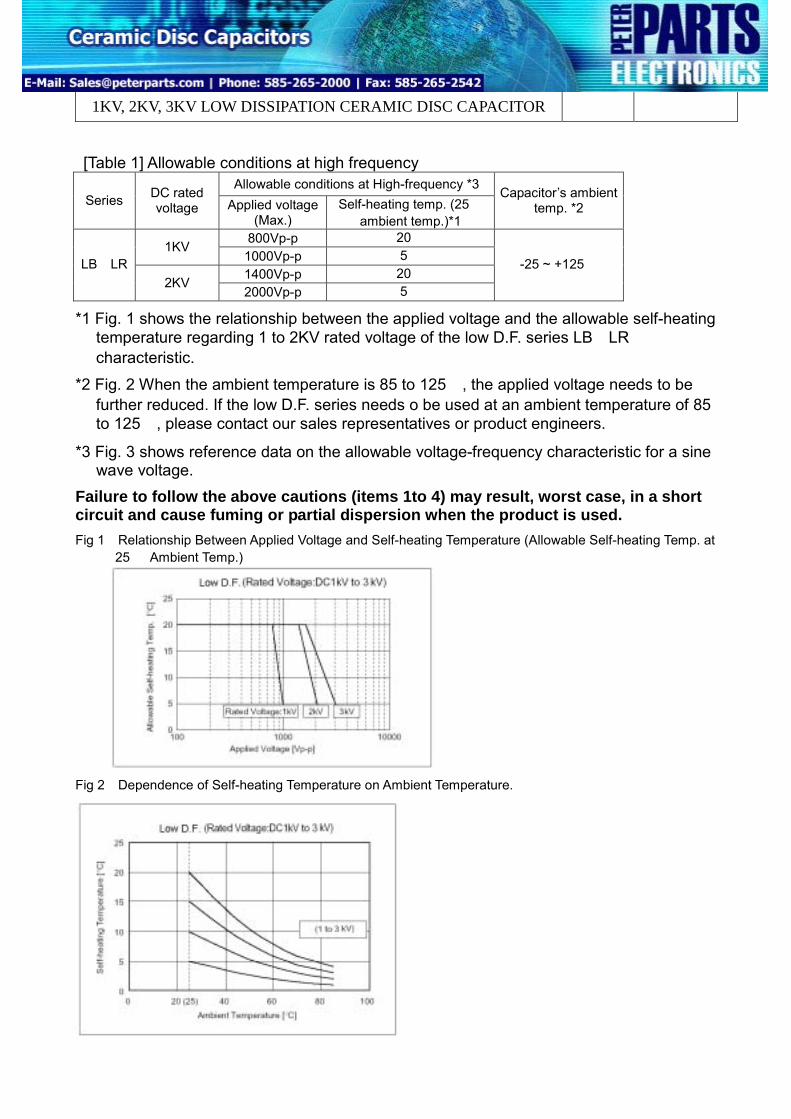
[Table 1] Allowable conditions at high frequency Allowable conditions at High-frequency *3
Series DC rated voltage Applied voltage
(Max.) Self-heating temp. (25℃
ambient temp.)*1
Capacitor’s ambient temp. *2
800Vp-p 20℃ 1KV
1000Vp-p 5℃ 1400Vp-p 20℃
LB、LR 2KV
2000Vp-p 5℃
-25 ~ +125℃
*1 Fig. 1 shows the relationship between the applied voltage and the allowable self-heating temperature regarding 1 to 2KV rated voltage of the low D.F. series LB、LR characteristic.
*2 Fig. 2 When the ambient temperature is 85 to 125℃, the applied voltage needs to be further reduced. If the low D.F. series needs o be used at an ambient temperature of 85 to 125℃, please contact our sales representatives or product engineers.
*3 Fig. 3 shows reference data on the allowable voltage-frequency characteristic for a sine wave voltage.
Failure to follow the above cautions (items 1to 4) may result, worst case, in a short circuit and cause fuming or partial dispersion when the product is used. Fig 1:Relationship Between Applied Voltage and Self-heating Temperature (Allowable Self-heating Temp. at
25℃ Ambient Temp.)
Fig 2:Dependence of Self-heating Temperature on Ambient Temperature.
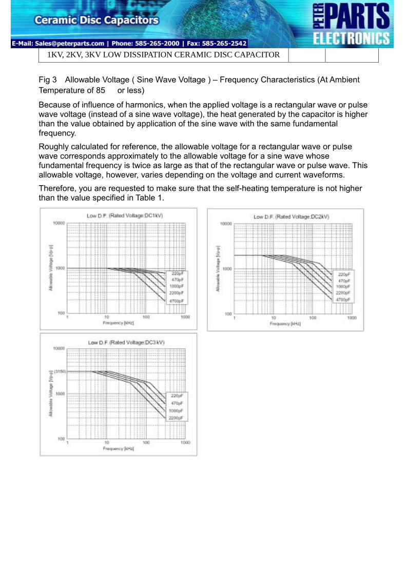
Fig 3:Allowable Voltage ( Sine Wave Voltage ) – Frequency Characteristics (At Ambient Temperature of 85℃ or less)
Because of influence of harmonics, when the applied voltage is a rectangular wave or pulse wave voltage (instead of a sine wave voltage), the heat generated by the capacitor is higher than the value obtained by application of the sine wave with the same fundamental frequency. Roughly calculated for reference, the allowable voltage for a rectangular wave or pulse wave corresponds approximately to the allowable voltage for a sine wave whose fundamental frequency is twice as large as that of the rectangular wave or pulse wave. This allowable voltage, however, varies depending on the voltage and current waveforms. Therefore, you are requested to make sure that the self-heating temperature is not higher than the value specified in Table 1.
2.Caution (Storage And Operating Condition) I. Operating And Storage Environment
The insulating coating of capacitors does not form a perfect seal; therefore, do not use or store capacitors in a corrosive atmosphere, especially where chloride gas, sulfide gas, acid, alkali, salt or the like are present. And avoid exposure to Moisture. Before cleaning, bonding or molding this product, verify that these processes do not affect product quality by testing the performance of a cleaned, bonded or molded product in the intended equipment. Store the capacitors where the temperature and relative humidity do not exceed –10 to 40 degrees centigrade and 15 to 85 %. Use capacitors within 6 months.
Failure to follow the above cautions may result, worst case, in a short circuit and cause fuming or partial dispersion when the product is used.
3.Caution (Soldering And Mounting) I. Vibration And Impact
Do not expose a capacitor or its leads to excessive shock or vibration during use.
II. Soldering When soldering this product to a Pcb / Pwb, do not exceed the solder heat resistance specification of the capacitor. Subjecting this product to excessive heating could melt the internal junction solder and may result in thermal shocks that can crack the ceramic element. When soldering capacitor with a soldering iron, it should be performed in following conditions. Temperature of iron-tip: 400 ℃ Max. Soldering iron wattage: 50W Max. Soldering time: 3.5 sec. Max.
Failure to follow the above cautions may result, worst case, in a short circuit and cause fuming or partial dispersion when the product is used.
4. Caution (Handling) Vibration And Impact
Do not expose a capacitor or its leads to excessive shock or vibration during use. Failure to follow the above cautions may result, worst case, in a short circuit and cause fuming or partial dispersion when the product is used.
1.Notice (Soldering And Mounting) Cleaning (ultrasonic cleaning) To perform ultrasonic cleaning, observe the following conditions. Rinse bath capacity: output of 20-watts per liter or less. Rinsing time: 5 min. Maximum. Do not vibrate the Pcb/Pwb directly. Excessive ultrasonic cleaning may lead to fatigue destruction of the lead wires.
2.Notice (Rating) Low D.F. series Capacitance might change greatly depending on the surrounding temperature or an applied voltage. So, it is not likely to be suitable for use in a time constant circuit. Please contact us if you need detailed information.