Journal of Physics: Conference Series OPEN ACCESS πShaper – Refractive Beam Shaping Optics for Advanced Laser Technologies To cite this article: Alexander Laskin and Vadim Laskin 2011 J. Phys.: Conf. Ser. 276 012171 View the article online for updates and enhancements. You may also like High-power laser diode array beam- shaping by rhomboid prism arrays Guoxing Zheng and Song Li - General solution of two-dimensional beam- shaping with two surfaces K-H Brenner - Nonlinear beam shaping in periodical (2) fork gratings with structural defects Tian Xiang Xu, Ru Wei Zhao and Shi Xun Dai - Recent citations Characterisation of a sub-20 ps temporal resolution pulse dilation photomultiplier tube S. G. Gales et al - Simran Agarwal et al - This content was downloaded from IP address 213.142.12.51 on 23/12/2021 at 16:50
Transcript
Journal of Physics Conference Series
OPEN ACCESS
πShaper ndash Refractive Beam Shaping Optics forAdvanced Laser TechnologiesTo cite this article Alexander Laskin and Vadim Laskin 2011 J Phys Conf Ser 276 012171
View the article online for updates and enhancements
You may also likeHigh-power laser diode array beam-shaping by rhomboid prism arraysGuoxing Zheng and Song Li
-
General solution of two-dimensional beam-shaping with two surfacesK-H Brenner
-
Nonlinear beam shaping in periodical (2)
fork gratings with structural defectsTian Xiang Xu Ru Wei Zhao and Shi XunDai
-
Recent citationsCharacterisation of a sub-20 ps temporalresolution pulse dilation photomultipliertubeS G Gales et al
-
Simran Agarwal et al-
This content was downloaded from IP address 2131421251 on 23122021 at 1650
πShaper - Refractive Beam Shaping Optics for Advanced Laser Technologies
Alexander Laskin1 Vadim Laskin
Molecular Technology (MolTech) GmbH Rudower Chaussee 29-31 12489 Berlin Germany
alexmt-berlincom
Abstract Laser beam shaping brings to various industrial and scientific laser techniques effects that improve their performance comparing to what can be achieved with using Gaussian or Gaussian-like laser beams more stability less tough positioning tolerances make the technologies easier to use higher efficiency of using of costly laser energy etc The task of such a transformation is solved by series of refractive beam shaping optics of field mapping type This solution is important in irradiating the cathode of Free Electron Lasers confocal microscopy biomedical fluorescence techniques many industrial technologies like welding cladding hardening various laser techniques in photovoltaics homogenizing of pump radiation by building powerful femtosecond lasers etc The refractive beam shapers can be used with TEM00 and multimode laser beams achromatic design provides the same conditions of beam shaping for several lasers of a certain spectrum range simultaneously low inherent losses allow to use them with powerful laser sources particular models can be implemented as Galilean Telescope without internal focusing or as Collimators This paper will describe the principles of operation design features of the achromatic refractive beam shapers there will be presented examples of beam intensity transformation and effects on material processing achieved in several industrial applications
1 Introduction The lasers are widely used in various applications in science and industry and their effective using is very important Typically the intensity distribution of laser sources is described by the Gaussian function provided by physics of creating the laser radiation From one side this Gaussian profile provides high energy concentration however from another side for many industrial scientific and life science applications it is not an optimum one because of non-uniform intensity distribution within the laser beam In plenty of laser techniques a homogenized laser beam is most preferable from the point of view of saving the energy and providing the same conditions of illumination or material treatment in the beam area Therefore the task of re-distribution of energy within the laser beam to provide uniform intensity profile is an actual scientific and industrial task In many cases a solution can be realized on the base of a family of refractive beam shaping systems πShaper
Unlike other beam shaping solutions like truncation of a beam by an aperture or attenuation by apodizing filters integration systems based on arrays of microlenses micromirrors prisms or DOE the πShaper realizes so called field mapping approach featuring by the intensity profile transformation 1 To whom any correspondence should be addressed
3rd International Photonics amp OptoElectronics Meetings (POEM 2010) IOP PublishingJournal of Physics Conference Series 276 (2011) 012171 doi1010881742-65962761012171
Published under licence by IOP Publishing Ltd 1
in a controlled manner by introducing a pre-determined wave aberration with after the intensity re-distribution its compensation As result accurate theoretically almost lossless transformation is provided and a collimated speckle-free beam is created
2 Principles of operation
21 Motivation ndash increasing efficiency of using laser energy All laser applications have specific features of interaction of material and laser radiation There is however something common for all single mode (TEM00) lasers mdash the Gaussian function of intensity distribution Therefore approximate evaluation of the efficiency of using laser energy can be done by considering just the geometrical features of the Gaussian function without taking into account effects accompanying laser treatment of materials like burning melting etc
The three-dimension intensity profile can be interpreted as a geometrical figure bounded by a horizontal plane and a surface of the Gaussian function I(r)
I (r) = I0 exp(-2Hr 2ω2 ) (1)
where r designates a variable beam radius in polar coordinates ω designates a waist radius of the Gaussian laser beam I0 is constant
Fig1 shows a section of such a figure its volume has physical sense of energy of the laser beam Letrsquos denominate by variables E1 E2 E3 different parts of that figure
bull E1 - an ldquoapexrdquo of Gauss function is an excess of intensity over the working level Ih very often this is a loss of energy or a source of overheating the central portion of a zone under treatment
bull E2 - ldquotailsrdquo of Gaussian distribution almost always this is a loss of energy or a source of unwished effects like heat affected zone (HAZ) and
bull E3 - ldquoeffective cylinderrdquo of energy
Figure 1 To evaluation of efficiency of using the laser energy
By mathematical transformation one can get following formulae to calculate the energy parts E1 E2 and E3
E1 = 1 ndash h + lnhsdoth E2 = h (2) E3 = ndash lnhsdoth E1+E2 = 1 + lnhsdoth
where h = Ih Imax
The results of calculations are presented on right diagram in Fig1 The unconditional energy loss E2 ldquotailsrdquo can reach a very high level - for example if a working
energy level Ih is half of maximum (h = 05 very often just this level is considered as a working one) the energy losses are 50 percent of full laser beam energy
3rd International Photonics amp OptoElectronics Meetings (POEM 2010) IOP PublishingJournal of Physics Conference Series 276 (2011) 012171 doi1010881742-65962761012171
2
In the case of laser treatment of thin films the energy part E1 ldquoapexrdquo of Gauss is also considered as a loss of energy because this part exceeds the working energy level Ih Thus both energy parts E1 and E2 are losses the sum E1 + E2 has sense of combined losses and minimum of this function is 063 In other words when treating thin films in the best case ldquoonlyrdquo 63 percent of energy is lost and 37 percent is effective
No doubt transformation of the original Gaussian shape to ldquoan effective cylinderrdquo called as a flattop or top hat profile would help to save laser energy and improve those technologies where uniform intensity is most desirable This transformation is a main function of the πShaper systems
22 Design features of the πShaper An idea of the πShaper operation is illustrated with Fig 2 Gaussian (or close to Gaussian) intensity distribution of a TEM00 or multimode laser beam is converted to a flat-top distribution (similar to a Greek letter π ) that stays invariable over long distance after the πShaper
Figure 2 Principle of the πShaper operation Figure 3 Example of optical layout
This transformation is realized through distortion of the beam wave front inside the optical system under the condition of conservation of energy this effect is illustrated with a picture in Fig 3 Mathematically this condition is formulated as follows
rin Rout xIin (r)sdotrsdotdr = xIout (R)sdotRsdotdR (3) 0 0
where r is an input beam radius in polar coordinates Iin (r) is a function of intensity distribution of the input laser beam section rin is a max radius of the input beam subjected to considered intensity distribution R is an output beam radius in polar coordinates Iout (R) is a function of intensity distribution of the output beam Rout is a max radius of the output beam resulting after the intensity redistribution
Another basic principle of a beam shaper is zero wave aberration this means the aberration introduced by first optical component is then compensated by the second one Other details of refractive beam shapers of field mapping type like πShaper can be found in publications [12345] here we will emphasize on some features important for their practical using
An essential design feature of the πShaper optical system is in consisting of two optical components and controlled wave front transformation in the space between them due to applying of special optical surfaces as result necessary intensity redistribution is achieved Another important feature of the πShaper optical design is zero or negligible for practical applications residual wave aberration this means equal path lengths for all rays of input beam passing through the optical system this condition is very important for practice since guarantees flat output wave front and avoidance of appearing undesirable interference fringes this provides also low output divergence and keeping the result intensity profile over long distance after the πShaper
One of important features of the πShaper optical systems over other approaches is in their achromatic design that guarantees simultaneous fulfillment of conditions of intensity redistribution and zero or negligible wave aberration for a certain spectral range as result the achromatic optical
3rd International Photonics amp OptoElectronics Meetings (POEM 2010) IOP PublishingJournal of Physics Conference Series 276 (2011) 012171 doi1010881742-65962761012171
3
systems provide the same operation at each wavelength of this spectral range This feature is realized through using materials with different dispersion characteristics
Providing of the same operation of the achromatic πShaper optical systems at each wavelength of the certain spectral range makes these systems very useful in the applications where several laser sources are applied simultaneously for example in spectroscopy fluorescence life science technologies confocal microscopy This feature is very important also in material processing technologies where various lasers are applied in one technology cycle for example by manufacturing the solar cells Another important application example is ultrashort pulse lasers like femtosecond TiSapphire lasers where small pulse duration is achieved due to wide spectral bandwidth of a laser source
To prevent internal focusing of a laser beam all πShaper optical systems realize so called Galilean type telescope this is a critical point for high power and short pulse laser applications
The πShaper are capable to work with TEM00 as well as multimode lasers Summarizing the most important features and basic principles of πShaper are bull telescopic or collimating refractive optical systems that transform Gaussian or close to
Gaussian intensity distribution of source laser beam to a flattop (or top-hat or uniform) one bull The initial laser beam can be either a TEM00 or a multimode one bull The uniform intensity is kept after the πShaper over a large distance bull There are available telescope models as well as systems with optical power like collimator bull The transformation is provided for a certain spectral range thus πShaper is an achromatic system bull Galilean design thus there is no internal focusing of a beam
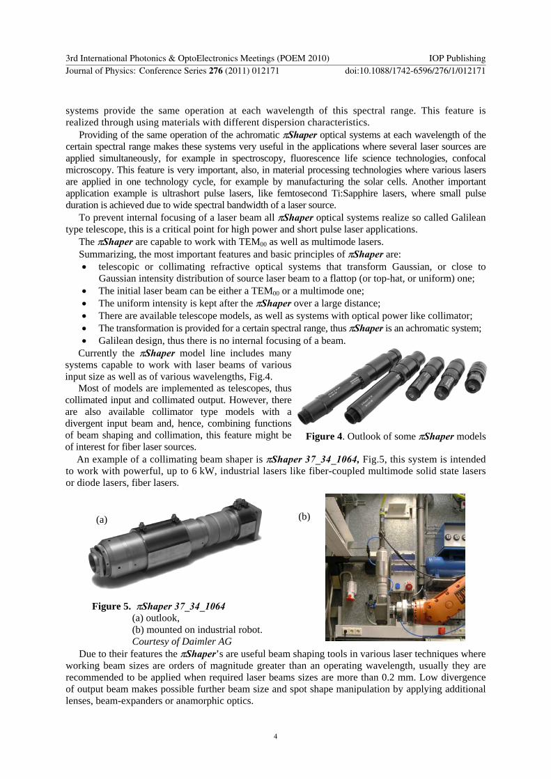
Currently the πShaper model line includes many systems capable to work with laser beams of various input size as well as of various wavelengths Fig4
Most of models are implemented as telescopes thus collimated input and collimated output However there are also available collimator type models with a divergent input beam and hence combining functions of beam shaping and collimation this feature might be of interest for fiber laser sources
Figure 4 Outlook of some πShaper models
An example of a collimating beam shaper is πShaper 37_34_1064 Fig5 this system is intended to work with powerful up to 6 kW industrial lasers like fiber-coupled multimode solid state lasers or diode lasers fiber lasers
Figure 5 πShaper 37_34_1064 (a) outlook (b) mounted on industrial robot Courtesy of Daimler AG
Due to their features the πShaperrsquos are useful beam shaping tools in various laser techniques where working beam sizes are orders of magnitude greater than an operating wavelength usually they are recommended to be applied when required laser beams sizes are more than 02 mm Low divergence of output beam makes possible further beam size and spot shape manipulation by applying additional lenses beam-expanders or anamorphic optics
(a) (b)
3rd International Photonics amp OptoElectronics Meetings (POEM 2010) IOP PublishingJournal of Physics Conference Series 276 (2011) 012171 doi1010881742-65962761012171
4
3 Examples of optical layouts on the base of πShaper
31 Beam Size manipulation with beam-expanders According to basic design the output beam after refractive field mapping beam shapers is round and has a pre-determined size for example in case of πShaper 6_6 the resulting beam diameter is about 6 mm For some tasks thatrsquos enough however most often it is necessary to change the beam diameter For example the applications where it is necessary to illuminate a Spatial Light Modulator or a mask with a collimated laser beam of uniform intensity usually require expansion of a beam after the refractive field mapping beam shaper At the same time many scientific and industrial tasks can be successfully solved when a collimated beam of uniform intensity and diameter of about 1 mm is provided some of them are laser welding hardening cladding etc
Common features of these beam transformations are varying the beam size and leaving the laser beam collimated Evidently this optical task can be easily solved by applying a beam-expander or a beam-reducer of telescopic type with an appropriate magnification factor the principle optical layouts are shown on Fig6
Figure 6 Examples of (a) reduction and (b) expansion of a beam after a πShaper
When variable final beam size is required one can apply a zoom beam-expander The beam expansion leads to extending of the space where a resulting beam profile is kept stable
because the diffraction effects influencing on the beam profile transformation become less strong another reason is in reduction of residual wave aberration always existing in real optical systems Therefore expansion factor is limited rather by capabilities of applied beam-expanders
In case of beam demagnification it is recommended donrsquot exceed a factor 10 since too much beam reduction would lead to increasing the residual wave aberrations and hence quicker beam profile deterioration when its propagation in space
32 Generation of linear spots with using anamorphotic optics There are many industrial applications which performance can be seriously improved by applying a linear shape of laser spot some examples of them are laser cleaning annealing hardening cladding Therefore the task of generation of a ldquolaser linerdquo is very important and refractive field mapping beam shapers in combination with special anamorphotic optics can be successfully used as a solution An example of a layout of such a combined system is shown on the below Fig 7
Figure 7 Generation of a ldquoLaser Linerdquo by attaching anamorphic optics to the πShaper
The collimated beam of uniform intensity is emerging from a refractive field mapping beam shaper and is then focused by an anamorphotic optics that is implemented as a pair of lenses one of them is an ordinary spherical lens and another one is a negative cylinder lens Due to the inherent astigmatism of the anamorphotic optics the beam is focused in one plane Y in Fig 7 but stays unfocused in the perpendicular plane X hence a spot of linear shape is created The length and the width of the line are defined by parameters of anamorphotic optics and aspect ratio can be up to 11000 The above layout was realized for the task of metal hardening with using radiation of high power fiber laser and a line of
(a)
(b)
3rd International Photonics amp OptoElectronics Meetings (POEM 2010) IOP PublishingJournal of Physics Conference Series 276 (2011) 012171 doi1010881742-65962761012171
5
10 mm length and about 05 mm width was realized more detailed description and results achieved are discussed later in the chapter of experimental results
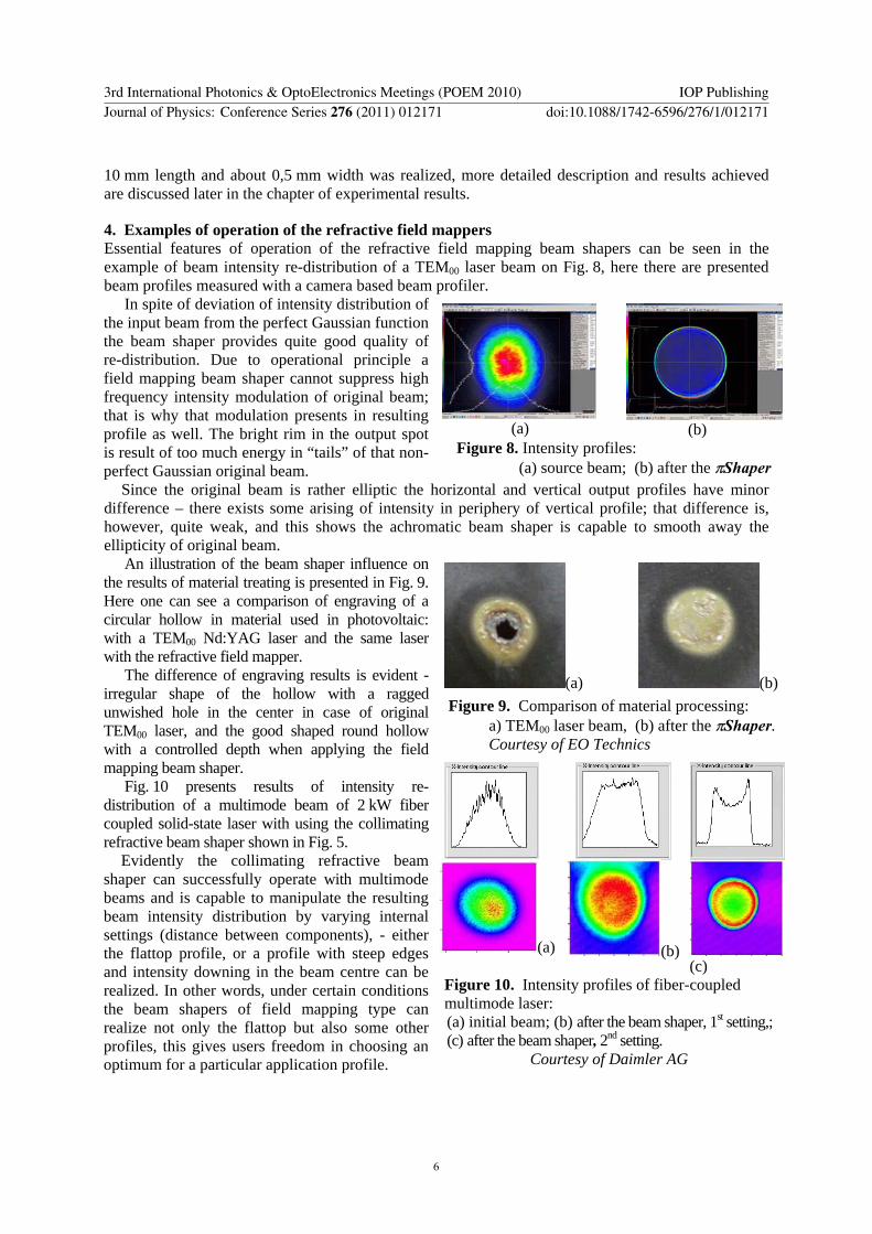
4 Examples of operation of the refractive field mappers Essential features of operation of the refractive field mapping beam shapers can be seen in the example of beam intensity re-distribution of a TEM00 laser beam on Fig 8 here there are presented beam profiles measured with a camera based beam profiler
(a)
(b)
In spite of deviation of intensity distribution of the input beam from the perfect Gaussian function the beam shaper provides quite good quality of re-distribution Due to operational principle a field mapping beam shaper cannot suppress high frequency intensity modulation of original beam that is why that modulation presents in resulting profile as well The bright rim in the output spot is result of too much energy in ldquotailsrdquo of that non-perfect Gaussian original beam
Figure 8 Intensity profiles (a) source beam (b) after the πShaper
Since the original beam is rather elliptic the horizontal and vertical output profiles have minor difference ndash there exists some arising of intensity in periphery of vertical profile that difference is however quite weak and this shows the achromatic beam shaper is capable to smooth away the ellipticity of original beam
(a) (b) Figure 9 Comparison of material processing a) TEM00 laser beam (b) after the πShaper Courtesy of EO Technics
(a) (b) (c)
An illustration of the beam shaper influence on the results of material treating is presented in Fig 9 Here one can see a comparison of engraving of a circular hollow in material used in photovoltaic with a TEM00 NdYAG laser and the same laser with the refractive field mapper
The difference of engraving results is evident - irregular shape of the hollow with a ragged unwished hole in the center in case of original TEM00 laser and the good shaped round hollow with a controlled depth when applying the field mapping beam shaper
Fig 10 presents results of intensity re-distribution of a multimode beam of 2 kW fiber coupled solid-state laser with using the collimating refractive beam shaper shown in Fig 5
Evidently the collimating refractive beam shaper can successfully operate with multimode beams and is capable to manipulate the resulting beam intensity distribution by varying internal settings (distance between components) - either the flattop profile or a profile with steep edges and intensity downing in the beam centre can be realized In other words under certain conditions the beam shapers of field mapping type can realize not only the flattop but also some other profiles this gives users freedom in choosing an optimum for a particular application profile
Figure 10 Intensity profiles of fiber-coupled multimode laser (a) initial beam (b) after the beam shaper 1st setting (c) after the beam shaper 2nd setting
Courtesy of Daimler AG
3rd International Photonics amp OptoElectronics Meetings (POEM 2010) IOP PublishingJournal of Physics Conference Series 276 (2011) 012171 doi1010881742-65962761012171
6
Focusing of a multimode beam after a refractive field mapping beam shaper leads to some useful effects The Fig 11 shows a comparison of view of caustics for multimode 2 kW solid state laser fiber-coupled to 600 micron fiber by focusing with using the same lens in 2 cases (a) with ordinary collimator and (b) with the πShaper 37_34_1064 as a collimator Evidently there is a difference in the beam profile behaviour in zone of image plane of a fiber end ndash in case of the beam shaper the caustic is characterized by an extended zone along the optical axis where the intensity profile is uniform and beam size stays almost invariable this is something like a ldquopipe of uniform intensityrdquo This feature makes it possible to achieve more stable and predictable results of welding brazing and many other applications where a uniform intensity profile is advisable while the extended ldquopipe of uniform intensityrdquo increases a tolerance extent on position of a tool with respect to a workpiece that simplifies applying of a laser technology
(a) (b)
Figure 11 Caustic view (a) Ordinary Collimator and Lens (b) Collimating beam shaper and Lens
The optical system described in section 32 and presented in Fig 7 was realised in IPG Photonics to generate a linear shape of the spot of multimode 3 kW fiber laser for laser hardening of metal parts sure this approach can be applied in many other technologies where a linear spot can improve their performance
Figure 12 Computer simulation of beam profile created in optical system described in Fig 7
The uniform intensity was provided over the long axis which length was about 10 mm the line width was about 05 mm Since it was planned to move the linear spot over a workpiece in direction perpendicular to the long axis the intensity profile in short axis wasnrsquot specified a main aim was to achieve as narrow as possible line
Results of numerical calculations for the optical system Fig 7 implemented as a πShaper 37_34_1064 with an anamorphotic system are shown in Fig 12 Results of intensity profile measurements in area of working plane are presented in Fig 13
Evidently there exists good correspondence between theoretical and experimental results
Let us note one important feature of the field mapping beam shapers that is very good seen in this example ndash
Figure 13 Results of measurements with using a beam profiler On left - 3D view of the spot On right ndash profiles in sections
Courtesy of IPG Photonics
3rd International Photonics amp OptoElectronics Meetings (POEM 2010) IOP PublishingJournal of Physics Conference Series 276 (2011) 012171 doi1010881742-65962761012171
7
capability to create not only uniform resulting profiles but some other beam shapes like so called ldquoinverse Gaussrdquo characterized by steep edges and downing of intensity in the centre Just this ldquoinverse Gaussrdquo profile was achieved in short axis of the final linear spot while focusing the laser radiation of multimode fiber laser Fig 13 on right Thus depending on settings the field mapping beam shapers provide various beam profiles and this flexibility is very useful and important in various laser technologies since gives the possibility to choose an optimum intensity distribution for a particular application
5 Conclusions
Growing complexity and variety of laser applications demand various designs of beam shaping optics Laser technologies and techniques where a required final laser beam should have other than Gaussian profile low divergence and the size orders of magnitude larger than a wavelength can be improved by applying refractive beam shapers of field mapping type like πShaper providing collimated beams of uniform intensity The specific features of refractive field mapping beam shapers provide flexibility in manipulation of the size and the spot shape by applying additional optical components Low divergence of output collimated beam near the same like in input beam leads to extended space after a beam shaper where a resulting beam profile is kept stable which in turn guarantees the long depth of field of a combined optical system At the same time very high factors of expansion demagnification as well as high aspect ratios of linear spot shapes become available These features in combination with inherent capability of field mappers to create not only flattop but also other beam profiles (ldquoinverse Gaussrdquo etc) make these devices a convenient tool to build beam shaping optics for various industrial and scientific applications
6 References
[1] Dickey FM Holswade SC (eds) 2000 Laser Beam Shaping Theory and Techniques (New York Marcel Dekker)
[2] Laskin AV 2009 Laser Beam Shaping X Proceedings of SPIE 7430 743003 [3] Laskin AV 2008 Achromatic optical system for beam shaping European Patent Application
EP1 998 215 A1 [4] Hoffnagle JA Jefferson CM 2000 Appl Opt 39 5488 [5] Kreuzer J 1969 Coherent light optical system yielding an output beam of desired intensity
distribution at a desired equiphase surface US Patent No 3 476 463
3rd International Photonics amp OptoElectronics Meetings (POEM 2010) IOP PublishingJournal of Physics Conference Series 276 (2011) 012171 doi1010881742-65962761012171
8
πShaper - Refractive Beam Shaping Optics for Advanced Laser Technologies
Alexander Laskin1 Vadim Laskin
Molecular Technology (MolTech) GmbH Rudower Chaussee 29-31 12489 Berlin Germany
alexmt-berlincom
Abstract Laser beam shaping brings to various industrial and scientific laser techniques effects that improve their performance comparing to what can be achieved with using Gaussian or Gaussian-like laser beams more stability less tough positioning tolerances make the technologies easier to use higher efficiency of using of costly laser energy etc The task of such a transformation is solved by series of refractive beam shaping optics of field mapping type This solution is important in irradiating the cathode of Free Electron Lasers confocal microscopy biomedical fluorescence techniques many industrial technologies like welding cladding hardening various laser techniques in photovoltaics homogenizing of pump radiation by building powerful femtosecond lasers etc The refractive beam shapers can be used with TEM00 and multimode laser beams achromatic design provides the same conditions of beam shaping for several lasers of a certain spectrum range simultaneously low inherent losses allow to use them with powerful laser sources particular models can be implemented as Galilean Telescope without internal focusing or as Collimators This paper will describe the principles of operation design features of the achromatic refractive beam shapers there will be presented examples of beam intensity transformation and effects on material processing achieved in several industrial applications
1 Introduction The lasers are widely used in various applications in science and industry and their effective using is very important Typically the intensity distribution of laser sources is described by the Gaussian function provided by physics of creating the laser radiation From one side this Gaussian profile provides high energy concentration however from another side for many industrial scientific and life science applications it is not an optimum one because of non-uniform intensity distribution within the laser beam In plenty of laser techniques a homogenized laser beam is most preferable from the point of view of saving the energy and providing the same conditions of illumination or material treatment in the beam area Therefore the task of re-distribution of energy within the laser beam to provide uniform intensity profile is an actual scientific and industrial task In many cases a solution can be realized on the base of a family of refractive beam shaping systems πShaper
Unlike other beam shaping solutions like truncation of a beam by an aperture or attenuation by apodizing filters integration systems based on arrays of microlenses micromirrors prisms or DOE the πShaper realizes so called field mapping approach featuring by the intensity profile transformation 1 To whom any correspondence should be addressed
3rd International Photonics amp OptoElectronics Meetings (POEM 2010) IOP PublishingJournal of Physics Conference Series 276 (2011) 012171 doi1010881742-65962761012171
Published under licence by IOP Publishing Ltd 1
in a controlled manner by introducing a pre-determined wave aberration with after the intensity re-distribution its compensation As result accurate theoretically almost lossless transformation is provided and a collimated speckle-free beam is created
2 Principles of operation
21 Motivation ndash increasing efficiency of using laser energy All laser applications have specific features of interaction of material and laser radiation There is however something common for all single mode (TEM00) lasers mdash the Gaussian function of intensity distribution Therefore approximate evaluation of the efficiency of using laser energy can be done by considering just the geometrical features of the Gaussian function without taking into account effects accompanying laser treatment of materials like burning melting etc
The three-dimension intensity profile can be interpreted as a geometrical figure bounded by a horizontal plane and a surface of the Gaussian function I(r)
I (r) = I0 exp(-2Hr 2ω2 ) (1)
where r designates a variable beam radius in polar coordinates ω designates a waist radius of the Gaussian laser beam I0 is constant
Fig1 shows a section of such a figure its volume has physical sense of energy of the laser beam Letrsquos denominate by variables E1 E2 E3 different parts of that figure
bull E1 - an ldquoapexrdquo of Gauss function is an excess of intensity over the working level Ih very often this is a loss of energy or a source of overheating the central portion of a zone under treatment
bull E2 - ldquotailsrdquo of Gaussian distribution almost always this is a loss of energy or a source of unwished effects like heat affected zone (HAZ) and
bull E3 - ldquoeffective cylinderrdquo of energy
Figure 1 To evaluation of efficiency of using the laser energy
By mathematical transformation one can get following formulae to calculate the energy parts E1 E2 and E3
E1 = 1 ndash h + lnhsdoth E2 = h (2) E3 = ndash lnhsdoth E1+E2 = 1 + lnhsdoth
where h = Ih Imax
The results of calculations are presented on right diagram in Fig1 The unconditional energy loss E2 ldquotailsrdquo can reach a very high level - for example if a working
energy level Ih is half of maximum (h = 05 very often just this level is considered as a working one) the energy losses are 50 percent of full laser beam energy
3rd International Photonics amp OptoElectronics Meetings (POEM 2010) IOP PublishingJournal of Physics Conference Series 276 (2011) 012171 doi1010881742-65962761012171
2
In the case of laser treatment of thin films the energy part E1 ldquoapexrdquo of Gauss is also considered as a loss of energy because this part exceeds the working energy level Ih Thus both energy parts E1 and E2 are losses the sum E1 + E2 has sense of combined losses and minimum of this function is 063 In other words when treating thin films in the best case ldquoonlyrdquo 63 percent of energy is lost and 37 percent is effective
No doubt transformation of the original Gaussian shape to ldquoan effective cylinderrdquo called as a flattop or top hat profile would help to save laser energy and improve those technologies where uniform intensity is most desirable This transformation is a main function of the πShaper systems
22 Design features of the πShaper An idea of the πShaper operation is illustrated with Fig 2 Gaussian (or close to Gaussian) intensity distribution of a TEM00 or multimode laser beam is converted to a flat-top distribution (similar to a Greek letter π ) that stays invariable over long distance after the πShaper
Figure 2 Principle of the πShaper operation Figure 3 Example of optical layout
This transformation is realized through distortion of the beam wave front inside the optical system under the condition of conservation of energy this effect is illustrated with a picture in Fig 3 Mathematically this condition is formulated as follows
rin Rout xIin (r)sdotrsdotdr = xIout (R)sdotRsdotdR (3) 0 0
where r is an input beam radius in polar coordinates Iin (r) is a function of intensity distribution of the input laser beam section rin is a max radius of the input beam subjected to considered intensity distribution R is an output beam radius in polar coordinates Iout (R) is a function of intensity distribution of the output beam Rout is a max radius of the output beam resulting after the intensity redistribution
Another basic principle of a beam shaper is zero wave aberration this means the aberration introduced by first optical component is then compensated by the second one Other details of refractive beam shapers of field mapping type like πShaper can be found in publications [12345] here we will emphasize on some features important for their practical using
An essential design feature of the πShaper optical system is in consisting of two optical components and controlled wave front transformation in the space between them due to applying of special optical surfaces as result necessary intensity redistribution is achieved Another important feature of the πShaper optical design is zero or negligible for practical applications residual wave aberration this means equal path lengths for all rays of input beam passing through the optical system this condition is very important for practice since guarantees flat output wave front and avoidance of appearing undesirable interference fringes this provides also low output divergence and keeping the result intensity profile over long distance after the πShaper
One of important features of the πShaper optical systems over other approaches is in their achromatic design that guarantees simultaneous fulfillment of conditions of intensity redistribution and zero or negligible wave aberration for a certain spectral range as result the achromatic optical
3rd International Photonics amp OptoElectronics Meetings (POEM 2010) IOP PublishingJournal of Physics Conference Series 276 (2011) 012171 doi1010881742-65962761012171
3
systems provide the same operation at each wavelength of this spectral range This feature is realized through using materials with different dispersion characteristics
Providing of the same operation of the achromatic πShaper optical systems at each wavelength of the certain spectral range makes these systems very useful in the applications where several laser sources are applied simultaneously for example in spectroscopy fluorescence life science technologies confocal microscopy This feature is very important also in material processing technologies where various lasers are applied in one technology cycle for example by manufacturing the solar cells Another important application example is ultrashort pulse lasers like femtosecond TiSapphire lasers where small pulse duration is achieved due to wide spectral bandwidth of a laser source
To prevent internal focusing of a laser beam all πShaper optical systems realize so called Galilean type telescope this is a critical point for high power and short pulse laser applications
The πShaper are capable to work with TEM00 as well as multimode lasers Summarizing the most important features and basic principles of πShaper are bull telescopic or collimating refractive optical systems that transform Gaussian or close to
Gaussian intensity distribution of source laser beam to a flattop (or top-hat or uniform) one bull The initial laser beam can be either a TEM00 or a multimode one bull The uniform intensity is kept after the πShaper over a large distance bull There are available telescope models as well as systems with optical power like collimator bull The transformation is provided for a certain spectral range thus πShaper is an achromatic system bull Galilean design thus there is no internal focusing of a beam
Currently the πShaper model line includes many systems capable to work with laser beams of various input size as well as of various wavelengths Fig4
Most of models are implemented as telescopes thus collimated input and collimated output However there are also available collimator type models with a divergent input beam and hence combining functions of beam shaping and collimation this feature might be of interest for fiber laser sources
Figure 4 Outlook of some πShaper models
An example of a collimating beam shaper is πShaper 37_34_1064 Fig5 this system is intended to work with powerful up to 6 kW industrial lasers like fiber-coupled multimode solid state lasers or diode lasers fiber lasers
Figure 5 πShaper 37_34_1064 (a) outlook (b) mounted on industrial robot Courtesy of Daimler AG
Due to their features the πShaperrsquos are useful beam shaping tools in various laser techniques where working beam sizes are orders of magnitude greater than an operating wavelength usually they are recommended to be applied when required laser beams sizes are more than 02 mm Low divergence of output beam makes possible further beam size and spot shape manipulation by applying additional lenses beam-expanders or anamorphic optics
(a) (b)
3rd International Photonics amp OptoElectronics Meetings (POEM 2010) IOP PublishingJournal of Physics Conference Series 276 (2011) 012171 doi1010881742-65962761012171
4
3 Examples of optical layouts on the base of πShaper
31 Beam Size manipulation with beam-expanders According to basic design the output beam after refractive field mapping beam shapers is round and has a pre-determined size for example in case of πShaper 6_6 the resulting beam diameter is about 6 mm For some tasks thatrsquos enough however most often it is necessary to change the beam diameter For example the applications where it is necessary to illuminate a Spatial Light Modulator or a mask with a collimated laser beam of uniform intensity usually require expansion of a beam after the refractive field mapping beam shaper At the same time many scientific and industrial tasks can be successfully solved when a collimated beam of uniform intensity and diameter of about 1 mm is provided some of them are laser welding hardening cladding etc
Common features of these beam transformations are varying the beam size and leaving the laser beam collimated Evidently this optical task can be easily solved by applying a beam-expander or a beam-reducer of telescopic type with an appropriate magnification factor the principle optical layouts are shown on Fig6
Figure 6 Examples of (a) reduction and (b) expansion of a beam after a πShaper
When variable final beam size is required one can apply a zoom beam-expander The beam expansion leads to extending of the space where a resulting beam profile is kept stable
because the diffraction effects influencing on the beam profile transformation become less strong another reason is in reduction of residual wave aberration always existing in real optical systems Therefore expansion factor is limited rather by capabilities of applied beam-expanders
In case of beam demagnification it is recommended donrsquot exceed a factor 10 since too much beam reduction would lead to increasing the residual wave aberrations and hence quicker beam profile deterioration when its propagation in space
32 Generation of linear spots with using anamorphotic optics There are many industrial applications which performance can be seriously improved by applying a linear shape of laser spot some examples of them are laser cleaning annealing hardening cladding Therefore the task of generation of a ldquolaser linerdquo is very important and refractive field mapping beam shapers in combination with special anamorphotic optics can be successfully used as a solution An example of a layout of such a combined system is shown on the below Fig 7
Figure 7 Generation of a ldquoLaser Linerdquo by attaching anamorphic optics to the πShaper
The collimated beam of uniform intensity is emerging from a refractive field mapping beam shaper and is then focused by an anamorphotic optics that is implemented as a pair of lenses one of them is an ordinary spherical lens and another one is a negative cylinder lens Due to the inherent astigmatism of the anamorphotic optics the beam is focused in one plane Y in Fig 7 but stays unfocused in the perpendicular plane X hence a spot of linear shape is created The length and the width of the line are defined by parameters of anamorphotic optics and aspect ratio can be up to 11000 The above layout was realized for the task of metal hardening with using radiation of high power fiber laser and a line of
(a)
(b)
3rd International Photonics amp OptoElectronics Meetings (POEM 2010) IOP PublishingJournal of Physics Conference Series 276 (2011) 012171 doi1010881742-65962761012171
5
10 mm length and about 05 mm width was realized more detailed description and results achieved are discussed later in the chapter of experimental results
4 Examples of operation of the refractive field mappers Essential features of operation of the refractive field mapping beam shapers can be seen in the example of beam intensity re-distribution of a TEM00 laser beam on Fig 8 here there are presented beam profiles measured with a camera based beam profiler
(a)
(b)
In spite of deviation of intensity distribution of the input beam from the perfect Gaussian function the beam shaper provides quite good quality of re-distribution Due to operational principle a field mapping beam shaper cannot suppress high frequency intensity modulation of original beam that is why that modulation presents in resulting profile as well The bright rim in the output spot is result of too much energy in ldquotailsrdquo of that non-perfect Gaussian original beam
Figure 8 Intensity profiles (a) source beam (b) after the πShaper
Since the original beam is rather elliptic the horizontal and vertical output profiles have minor difference ndash there exists some arising of intensity in periphery of vertical profile that difference is however quite weak and this shows the achromatic beam shaper is capable to smooth away the ellipticity of original beam
(a) (b) Figure 9 Comparison of material processing a) TEM00 laser beam (b) after the πShaper Courtesy of EO Technics
(a) (b) (c)
An illustration of the beam shaper influence on the results of material treating is presented in Fig 9 Here one can see a comparison of engraving of a circular hollow in material used in photovoltaic with a TEM00 NdYAG laser and the same laser with the refractive field mapper
The difference of engraving results is evident - irregular shape of the hollow with a ragged unwished hole in the center in case of original TEM00 laser and the good shaped round hollow with a controlled depth when applying the field mapping beam shaper
Fig 10 presents results of intensity re-distribution of a multimode beam of 2 kW fiber coupled solid-state laser with using the collimating refractive beam shaper shown in Fig 5
Evidently the collimating refractive beam shaper can successfully operate with multimode beams and is capable to manipulate the resulting beam intensity distribution by varying internal settings (distance between components) - either the flattop profile or a profile with steep edges and intensity downing in the beam centre can be realized In other words under certain conditions the beam shapers of field mapping type can realize not only the flattop but also some other profiles this gives users freedom in choosing an optimum for a particular application profile
Figure 10 Intensity profiles of fiber-coupled multimode laser (a) initial beam (b) after the beam shaper 1st setting (c) after the beam shaper 2nd setting
Courtesy of Daimler AG
3rd International Photonics amp OptoElectronics Meetings (POEM 2010) IOP PublishingJournal of Physics Conference Series 276 (2011) 012171 doi1010881742-65962761012171
6
Focusing of a multimode beam after a refractive field mapping beam shaper leads to some useful effects The Fig 11 shows a comparison of view of caustics for multimode 2 kW solid state laser fiber-coupled to 600 micron fiber by focusing with using the same lens in 2 cases (a) with ordinary collimator and (b) with the πShaper 37_34_1064 as a collimator Evidently there is a difference in the beam profile behaviour in zone of image plane of a fiber end ndash in case of the beam shaper the caustic is characterized by an extended zone along the optical axis where the intensity profile is uniform and beam size stays almost invariable this is something like a ldquopipe of uniform intensityrdquo This feature makes it possible to achieve more stable and predictable results of welding brazing and many other applications where a uniform intensity profile is advisable while the extended ldquopipe of uniform intensityrdquo increases a tolerance extent on position of a tool with respect to a workpiece that simplifies applying of a laser technology
(a) (b)
Figure 11 Caustic view (a) Ordinary Collimator and Lens (b) Collimating beam shaper and Lens
The optical system described in section 32 and presented in Fig 7 was realised in IPG Photonics to generate a linear shape of the spot of multimode 3 kW fiber laser for laser hardening of metal parts sure this approach can be applied in many other technologies where a linear spot can improve their performance
Figure 12 Computer simulation of beam profile created in optical system described in Fig 7
The uniform intensity was provided over the long axis which length was about 10 mm the line width was about 05 mm Since it was planned to move the linear spot over a workpiece in direction perpendicular to the long axis the intensity profile in short axis wasnrsquot specified a main aim was to achieve as narrow as possible line
Results of numerical calculations for the optical system Fig 7 implemented as a πShaper 37_34_1064 with an anamorphotic system are shown in Fig 12 Results of intensity profile measurements in area of working plane are presented in Fig 13
Evidently there exists good correspondence between theoretical and experimental results
Let us note one important feature of the field mapping beam shapers that is very good seen in this example ndash
Figure 13 Results of measurements with using a beam profiler On left - 3D view of the spot On right ndash profiles in sections
Courtesy of IPG Photonics
3rd International Photonics amp OptoElectronics Meetings (POEM 2010) IOP PublishingJournal of Physics Conference Series 276 (2011) 012171 doi1010881742-65962761012171
7
capability to create not only uniform resulting profiles but some other beam shapes like so called ldquoinverse Gaussrdquo characterized by steep edges and downing of intensity in the centre Just this ldquoinverse Gaussrdquo profile was achieved in short axis of the final linear spot while focusing the laser radiation of multimode fiber laser Fig 13 on right Thus depending on settings the field mapping beam shapers provide various beam profiles and this flexibility is very useful and important in various laser technologies since gives the possibility to choose an optimum intensity distribution for a particular application
5 Conclusions
Growing complexity and variety of laser applications demand various designs of beam shaping optics Laser technologies and techniques where a required final laser beam should have other than Gaussian profile low divergence and the size orders of magnitude larger than a wavelength can be improved by applying refractive beam shapers of field mapping type like πShaper providing collimated beams of uniform intensity The specific features of refractive field mapping beam shapers provide flexibility in manipulation of the size and the spot shape by applying additional optical components Low divergence of output collimated beam near the same like in input beam leads to extended space after a beam shaper where a resulting beam profile is kept stable which in turn guarantees the long depth of field of a combined optical system At the same time very high factors of expansion demagnification as well as high aspect ratios of linear spot shapes become available These features in combination with inherent capability of field mappers to create not only flattop but also other beam profiles (ldquoinverse Gaussrdquo etc) make these devices a convenient tool to build beam shaping optics for various industrial and scientific applications
6 References
[1] Dickey FM Holswade SC (eds) 2000 Laser Beam Shaping Theory and Techniques (New York Marcel Dekker)
[2] Laskin AV 2009 Laser Beam Shaping X Proceedings of SPIE 7430 743003 [3] Laskin AV 2008 Achromatic optical system for beam shaping European Patent Application
EP1 998 215 A1 [4] Hoffnagle JA Jefferson CM 2000 Appl Opt 39 5488 [5] Kreuzer J 1969 Coherent light optical system yielding an output beam of desired intensity
distribution at a desired equiphase surface US Patent No 3 476 463
3rd International Photonics amp OptoElectronics Meetings (POEM 2010) IOP PublishingJournal of Physics Conference Series 276 (2011) 012171 doi1010881742-65962761012171
8
capability to create not only uniform resulting profiles but some other beam shapes like so called ldquoinverse Gaussrdquo characterized by steep edges and downing of intensity in the centre Just this ldquoinverse Gaussrdquo profile was achieved in short axis of the final linear spot while focusing the laser radiation of multimode fiber laser Fig 13 on right Thus depending on settings the field mapping beam shapers provide various beam profiles and this flexibility is very useful and important in various laser technologies since gives the possibility to choose an optimum intensity distribution for a particular application
5 Conclusions
Growing complexity and variety of laser applications demand various designs of beam shaping optics Laser technologies and techniques where a required final laser beam should have other than Gaussian profile low divergence and the size orders of magnitude larger than a wavelength can be improved by applying refractive beam shapers of field mapping type like πShaper providing collimated beams of uniform intensity The specific features of refractive field mapping beam shapers provide flexibility in manipulation of the size and the spot shape by applying additional optical components Low divergence of output collimated beam near the same like in input beam leads to extended space after a beam shaper where a resulting beam profile is kept stable which in turn guarantees the long depth of field of a combined optical system At the same time very high factors of expansion demagnification as well as high aspect ratios of linear spot shapes become available These features in combination with inherent capability of field mappers to create not only flattop but also other beam profiles (ldquoinverse Gaussrdquo etc) make these devices a convenient tool to build beam shaping optics for various industrial and scientific applications
6 References
[1] Dickey FM Holswade SC (eds) 2000 Laser Beam Shaping Theory and Techniques (New York Marcel Dekker)
[2] Laskin AV 2009 Laser Beam Shaping X Proceedings of SPIE 7430 743003 [3] Laskin AV 2008 Achromatic optical system for beam shaping European Patent Application
EP1 998 215 A1 [4] Hoffnagle JA Jefferson CM 2000 Appl Opt 39 5488 [5] Kreuzer J 1969 Coherent light optical system yielding an output beam of desired intensity
distribution at a desired equiphase surface US Patent No 3 476 463
3rd International Photonics amp OptoElectronics Meetings (POEM 2010) IOP PublishingJournal of Physics Conference Series 276 (2011) 012171 doi1010881742-65962761012171