15
Point Busaco Revetment Detailed Design Seashore Engineering Pty Ltd December 2013 Report SE009-01-Rev1
Point Busaco Revetment Detailed Design
Seashore Engineering Pty Ltd December 2013
Report SE009-01-Rev1
SE009-01-Rev1 Point Busaco Revetment Detailed Design i
Table of Contents 1. Introduction ............................................................................................................. 1
1.1. Project Background .................................................................................................... 1
2. Design Refinement ................................................................................................... 3
2.1. Selection of Rock Type ............................................................................................... 3
2.2. Rock Requirements .................................................................................................... 3
2.3. Excavation and Fill Volumes ....................................................................................... 3
2.4. Short Groyne Design .................................................................................................. 4
3. Monitoring and Maintenance Plan ............................................................................ 6
4. References................................................................................................................ 8
Appendix A Potential Rock Sources ............................................................................... 9
Appendix A.1 Quarry Inspection................................................................................... 9
Appendix A.2 Alternative Rock Sources ...................................................................... 10
Appendix B Drawings ................................................................................................. 11
List of Figures Figure 1: Framework for Construction of the Provision Short Groyne ..................................... 4
List of Tables Table 1: Excavation and Fill Volumes for the Revetment .......................................................... 3
Table 2: Groyne Effectiveness ................................................................................................... 5
Table 3: Revetment and Groyne Structural Life Cycle ............................................................... 6
Table 4: Monitoring and Maintenance Program ....................................................................... 7
Document Control Index Author Date Review Date Comment
Rev0 G.McCormack 01.11.2013 M.Eliot 6.11.2013 Internal Review
Rev1 G.McCormack 02.12.2013 D.Lantry 21.11.2013 Client Review
SE009-01-Rev1 Point Busaco Revetment Detailed Design 1
1. Introduction
This report was commissioned by the Bunbury Port Authority and details the coastal
engineering design basis for development of the Point Busaco revetment from a preliminary
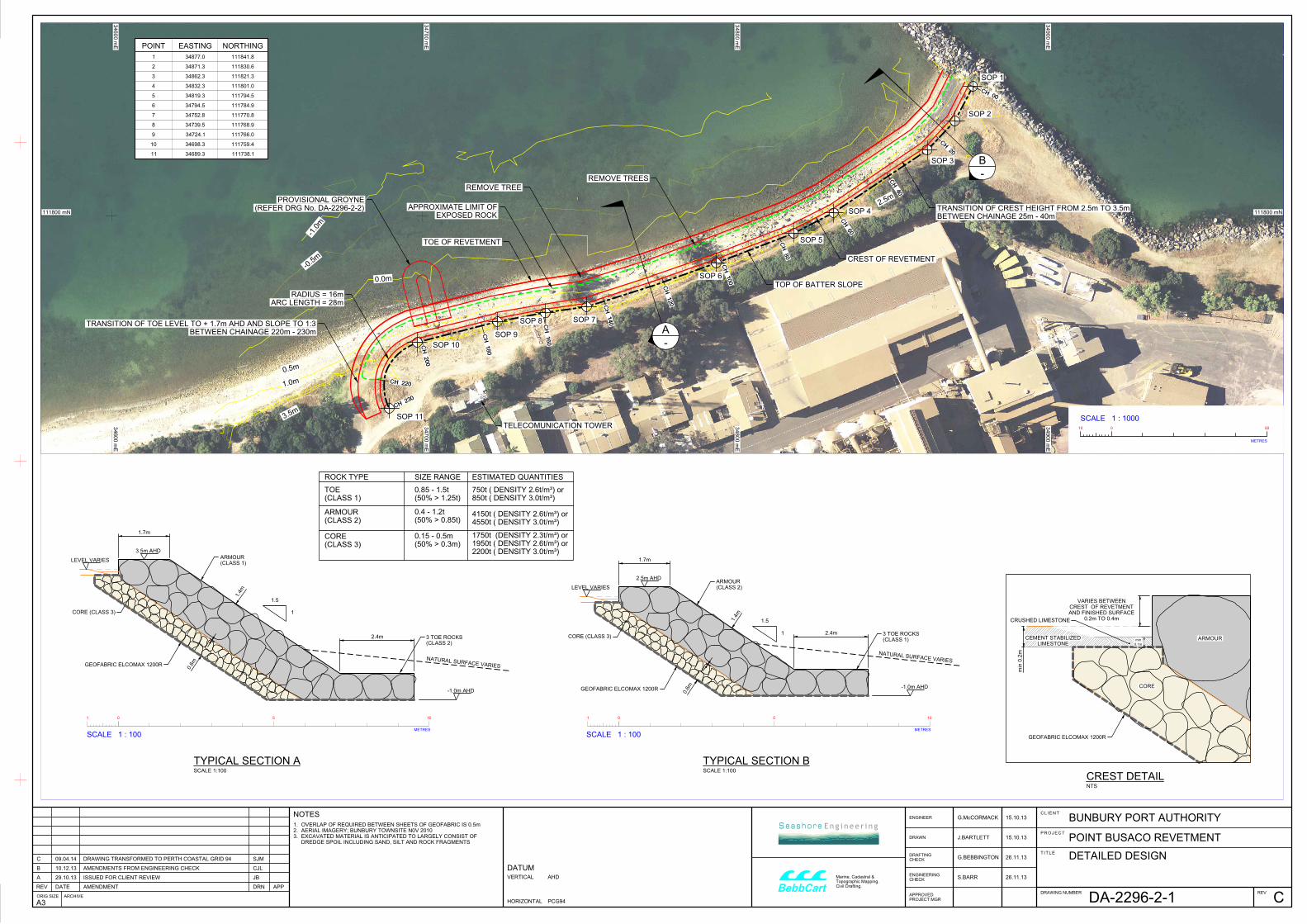
detailed (Damara WA 2011) to a detailed level as shown in Drawing DA 2296-2-1. This has
included:
Selection of rock types and minimum density parametres;
Design of short groyne at the western end to 'hold' a beach at the toe of the revetment thereby reducing the risk of toe destabilisation;
Estimates for the total volumes of excavation and fill required for construction based on a survey conducted on the 30th August 2013;
Identifying set-out points for construction;
Development of design drawings and technical specifications suitable for tendering and construction (Report SE009-02);
Development of a monitoring and maintenance plan.
The rock revetment provides coastal protection to the Cristals lease area and has been
designed to maintain pedestrian and emergency vehicle access along an existing access
track. The revetment is 230m long west of the Point Busaco groyne and its armour layer is to
be constructed from either granite or basalt rock with a minimum density of 2.6 tonnes per
cubic metre.
A 50 year average recurrence interval design criteria has been selected, which implies a
design working life of 25 years following to AS4997. It is recognised that this does not
represent the length of time the revetment will last, as minor maintenance of rock armoured
coastal protection structures can significantly extend the design life and alternatively
inadequate maintenance can significantly reduce the design life. Furthermore, rock armour
structures have a high residual capacity, such that they maintain a high level of functionality
following minor damage.
1.1. PROJECT BACKGROUND
From 2003, the Bunbury Port Authority has identified ongoing erosion to the west of the
Inner Harbour has increased the threat to the port access track adjacent to the Cristals site.
In badly affected areas undermining has required track relocation. By 2011, the erosion had
progressed to a degree where further relocation was considered impractical.
Bunbury Port Authority commissioned Damara WA (one of two companies forming Seashore
Engineering) in late 2011, to undertake a preliminary detailed design for a 230m rock
revetment (Point Busaco revetment) to provide erosion protection to the Cristals site, with
the revetment designed to maintain the existing buffer currently used for access. The
design consisted of a layout and cross-section and considered the following:
Stability of rock armour under wave attack;
A minimum trafficable width of four metres from the trees adjacent to the boundary fence plus an additional clearance of 1m;
Overtopping levels and management of drainage;
SE009-01-Rev1 Point Busaco Revetment Detailed Design 2
Practical construction limits for revetment toe construction in the southwest of Western Australia;
Major pathways for adaptation of the revetment.
Potential costs were derived for three alternative rock types (basalt, granite or lateritic ironstone) based on potential rock sources;
As part of design investigations, it was identified that the revetment is likely to transfer
erosive pressure to the west where existing infrastructure towards the centre of Koombana
Beach already has limited foreshore setback. Facilities potentially under threat include the
Dolphin Discovery Centre, footpaths, roads, and car parks. The City of Bunbury, with the
support of Bunbury Port Authority and the WA Department of Transport subsequently
commissioned Seashore Engineering to investigate erosion occurring at Koombana Beach
and determine an appropriate coastal management strategy that achieves optimal
outcomes for both the short and long term (Seashore Engineering 2013).
The recommended coastal management strategy for Koombana Beach was to construct
Point Busaco revetment and undertake ongoing renourishment works for the central and
eastern parts of the beach, using material supplied from the Outer Harbour sand traps. It is
recognised that how the City of Bunbury chooses to manage Koombana Beach will have
implications on the vulnerability of the revetment to toe destabilisation, with the level of
renourishment largely determining the amount of sand at the toe of the structure.
The Bunbury Port Authority has indicated they are willing to hold the construction of the
revetment until the City of Bunbury has decided on its management strategy or the
encroachment of erosion provides an immediate threat to infrastructure. It is recognised
that this position may be challenged if erosion is sufficiently severe to warrant emergency
works to protect infrastructure.
SE009-01-Rev1 Point Busaco Revetment Detailed Design 3
2. Design Refinement
2.1. SELECTION OF ROCK TYPE
The design is based on rock armour units with a minimum density of 2.6 tonnes per cubic
metre allowing for the use of either granite or basalt rock. These rock types are typically
preferred materials to provide longevity for coastal protection works, while they also
provide appearance consistent with other existing rock structures.
Possible cost savings were identified in the preliminary design phase for the use of lateritic
ironstone. This material will be considered for core rock only if it has a minimum density of
2.2 tonnes per cubic metre. As density of rock armour is a major design parameter along
with the highly variable nature of lateritic ironstone availability (Damara WA 2011) and
uncertainty of the timing of the works, no further consideration has been given to its use for
rock armour.
2.2. ROCK REQUIREMENTS
The stable median armour size of 0.85 tonnes and appropriate size ranges previously
calculated for a density of 2.6 tonnes per cubic metre has been used in the design (Damara
WA 2011). Larger rock sizes are recommended for the toe, where a relative absence of rock
interlocking reduces stability, requiring a median mass of approximately 1.5 times the stable
armour size.
It is recognised that if basalt rock is used in the Works which typically has a density of 3.0
tonnes per cubic metre, extra stability will be provided. Basalt rock will generally result in a
armour layer thickness reducing from 1.4m to 1.3m.
To allow for screening with a typical grizzly, the core rock size range has been adjusted to
0.15-0.5m, with the median diameter remaining at 0.3m.
2.3. EXCAVATION AND FILL VOLUMES
In situ material located along the beach and erosion scarp consists of dredge spoil including
sand, silt and rock fragments. Excavation and fill volumes required for construction of the
revetment have been estimated based on a survey of the foreshore carried out by Thomsons
Surveying Consultants on the 30th August 2013 (Table 1).
Table 1: Excavation and Fill Volumes for the Revetment
Total Excavation 3,200m3
Total Fill 600m3
Any excavated material considered unsuitable for use as fill and for placement along the beach in
front will need to be transported offsite and disposed of appropriately.
SE009-01-Rev1 Point Busaco Revetment Detailed Design 4
The revetment has been design to maintain a minimum trafficable width of four metres
from the trees adjacent to the boundary fence plus an additional clearance of 1m to
facilitate potential upgrading if required over extended structural life. Subsequently the
majority of the 600m3 of fill is required where the erosion scarp has encroached on the
access track between chainages 60 and 140m. The fill required for this section should be
sourced from suitable material excavated from adjacent areas, requiring stockpiling.
2.4. SHORT GROYNE DESIGN
Although toe rock is an considered an effective means of reducing the risk of toe
undermining and it enables a degree of damage to occur without causing expensive repairs,
toe undermining remains of significant concern due to the potential for ongoing westerly
transport and scour during extreme events.
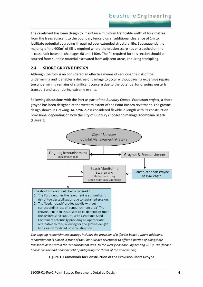
Following discussions with the Port as part of the Bunbury Coastal Protection project, a short
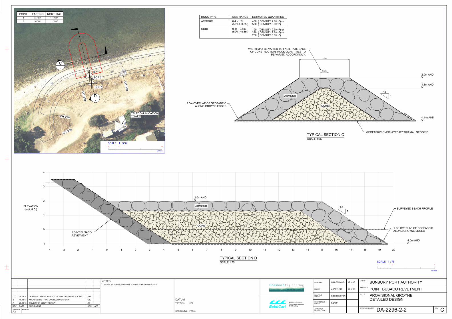
groyne has been designed at the western extent of the Point Busaco revetment. The groyne
design shown in Drawing DA-2296-2-2 is considered flexible in length with its construction
provisional depending on how the City of Bunbury chooses to manage Koombana Beach
(Figure 1).
The ongoing renourishment strategy includes the provision of a 'feeder beach', where additional
renourishment is placed in front of the Point Busaco revetment to offset a portion of alongshore
transport losses within the 'renourishment area' to the west (Seashore Engineering 2013). The 'feeder
beach' has the additional benefit of mitigating the threat of toe undermining.
Figure 1: Framework for Construction of the Provision Short Groyne
SE009-01-Rev1 Point Busaco Revetment Detailed Design 5
Orientation: The groyne is orientated to 344°N, perpendicular to the face of the revetment.
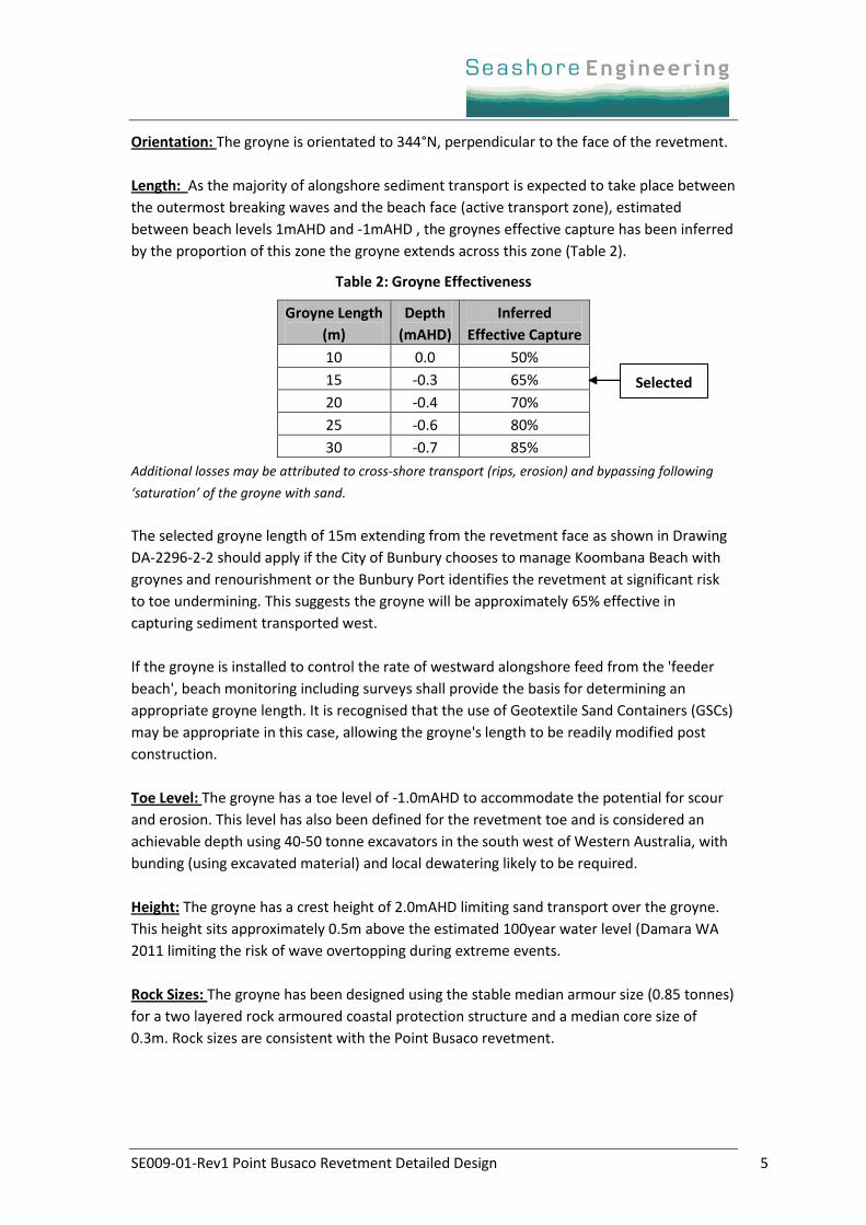
Length: As the majority of alongshore sediment transport is expected to take place between
the outermost breaking waves and the beach face (active transport zone), estimated
between beach levels 1mAHD and -1mAHD , the groynes effective capture has been inferred
by the proportion of this zone the groyne extends across this zone (Table 2).
Table 2: Groyne Effectiveness
Groyne Length
(m)
Depth
(mAHD)
Inferred
Effective Capture
10 0.0 50%
15 -0.3 65%
20 -0.4 70%
25 -0.6 80%
30 -0.7 85%
Additional losses may be attributed to cross-shore transport (rips, erosion) and bypassing following
‘saturation’ of the groyne with sand.
The selected groyne length of 15m extending from the revetment face as shown in Drawing
DA-2296-2-2 should apply if the City of Bunbury chooses to manage Koombana Beach with
groynes and renourishment or the Bunbury Port identifies the revetment at significant risk
to toe undermining. This suggests the groyne will be approximately 65% effective in
capturing sediment transported west.
If the groyne is installed to control the rate of westward alongshore feed from the 'feeder
beach', beach monitoring including surveys shall provide the basis for determining an
appropriate groyne length. It is recognised that the use of Geotextile Sand Containers (GSCs)
may be appropriate in this case, allowing the groyne's length to be readily modified post
construction.
Toe Level: The groyne has a toe level of ‐1.0mAHD to accommodate the potential for scour
and erosion. This level has also been defined for the revetment toe and is considered an
achievable depth using 40‐50 tonne excavators in the south west of Western Australia, with
bunding (using excavated material) and local dewatering likely to be required.
Height: The groyne has a crest height of 2.0mAHD limiting sand transport over the groyne.
This height sits approximately 0.5m above the estimated 100year water level (Damara WA
2011 limiting the risk of wave overtopping during extreme events.
Rock Sizes: The groyne has been designed using the stable median armour size (0.85 tonnes)
for a two layered rock armoured coastal protection structure and a median core size of
0.3m. Rock sizes are consistent with the Point Busaco revetment.
Selected
SE009-01-Rev1 Point Busaco Revetment Detailed Design 6
3. Monitoring and Maintenance Plan
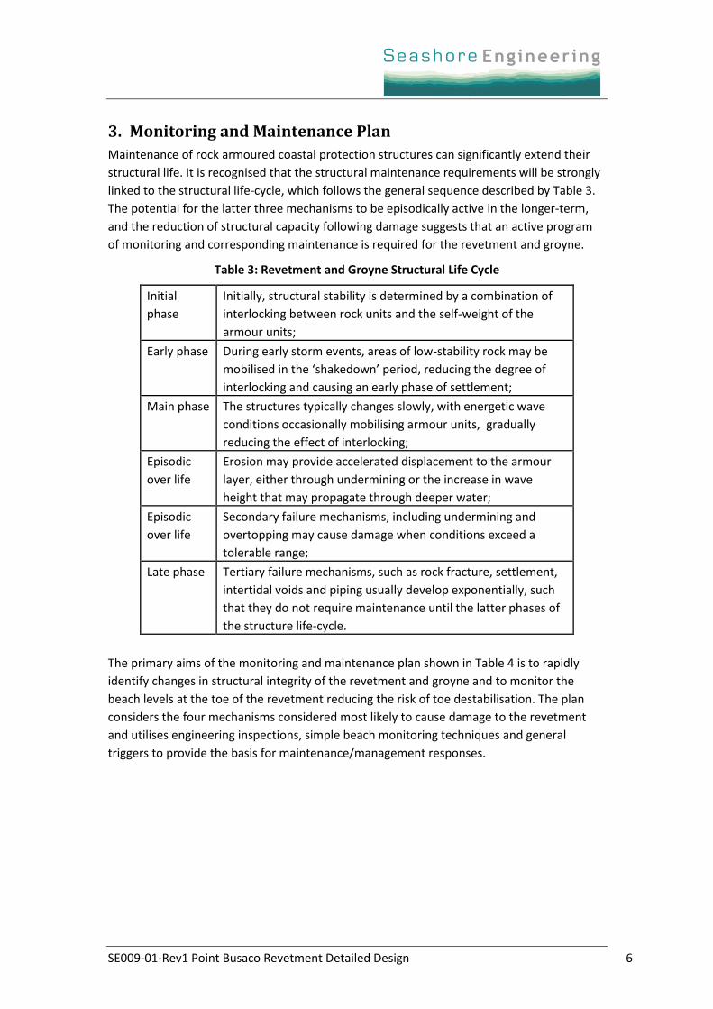
Maintenance of rock armoured coastal protection structures can significantly extend their
structural life. It is recognised that the structural maintenance requirements will be strongly
linked to the structural life-cycle, which follows the general sequence described by Table 3.
The potential for the latter three mechanisms to be episodically active in the longer-term,
and the reduction of structural capacity following damage suggests that an active program
of monitoring and corresponding maintenance is required for the revetment and groyne.
Table 3: Revetment and Groyne Structural Life Cycle
Initial
phase
Initially, structural stability is determined by a combination of
interlocking between rock units and the self-weight of the
armour units;
Early phase During early storm events, areas of low-stability rock may be
mobilised in the ‘shakedown’ period, reducing the degree of
interlocking and causing an early phase of settlement;
Main phase The structures typically changes slowly, with energetic wave
conditions occasionally mobilising armour units, gradually
reducing the effect of interlocking;
Episodic
over life
Erosion may provide accelerated displacement to the armour
layer, either through undermining or the increase in wave
height that may propagate through deeper water;
Episodic
over life
Secondary failure mechanisms, including undermining and
overtopping may cause damage when conditions exceed a
tolerable range;
Late phase Tertiary failure mechanisms, such as rock fracture, settlement,
intertidal voids and piping usually develop exponentially, such
that they do not require maintenance until the latter phases of
the structure life-cycle.
The primary aims of the monitoring and maintenance plan shown in Table 4 is to rapidly
identify changes in structural integrity of the revetment and groyne and to monitor the
beach levels at the toe of the revetment reducing the risk of toe destabilisation. The plan
considers the four mechanisms considered most likely to cause damage to the revetment
and utilises engineering inspections, simple beach monitoring techniques and general
triggers to provide the basis for maintenance/management responses.
SE009-01-Rev1 Point Busaco Revetment Detailed Design 7
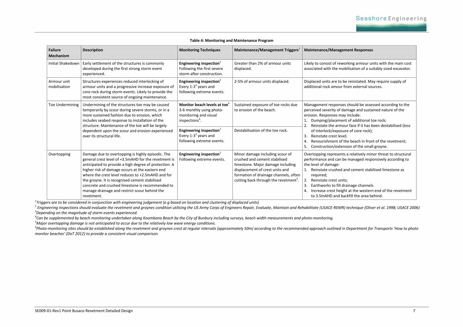
Table 4: Monitoring and Maintenance Program
Failure
Mechanism
Description
Monitoring Techniques Maintenance/Management Triggers1 Maintenance/Management Responses
Initial Shakedown Early settlement of the structures is commonly developed during the first strong storm event experienced.
Engineering inspection2 Following the first severe storm after construction.
Greater than 2% of armour units displaced.
Likely to consist of reworking armour units with the main cost associated with the mobilisation of a suitably sized excavator.
Armour unit mobilisation
Structures experiences reduced interlocking of armour units and a progressive increase exposure of core rock during storm events. Likely to provide the most consistent source of ongoing maintenance.
Engineering inspection2 Every 1-33 years and following extreme events.
2-5% of armour units displaced. Displaced units are to be reinstated. May require supply of additional rock amour from external sources.
Toe Undermining Undermining of the structures toe may be caused temporarily by scour during severe storms, or in a more sustained fashion due to erosion, which includes seabed response to installation of the structure. Maintenance of the toe will be largely dependent upon the scour and erosion experienced over its structural life.
Monitor beach levels at toe4 3-6 monthly using photo-monitoring and visual inspections6.
Sustained exposure of toe rocks due to erosion of the beach.
Management responses should be assessed according to the perceived severity of damage and sustained nature of the erosion. Responses may include: 1. Dumping/placement of additional toe rock; 2. Reinstate the armour face if it has been destabilised (loss
of interlock/exposure of core rock); 3. Reinstate crest level; 4. Renourishment of the beach in front of the revetment; 5. Construction/extension of the small groyne.
Engineering inspection2 Every 1-33 years and following extreme events.
Destabilisation of the toe rock.
Overtopping Damage due to overtopping is highly episodic. The general crest level of +3.5mAHD for the revetment is anticipated to provide a high degree of protection. A higher risk of damage occurs at the eastern end where the crest level reduces to +2.5mAHD and for the groyne. It is recognised cement stabilised concrete and crushed limestone is recommended to manage drainage and restrict scour behind the revetment.
Engineering inspection2 Following extreme events.
Minor damage including scour of crushed and cement stabilised limestone. Major damage including displacement of crest units and formation of drainage channels, often cutting back through the revetment5.
Overtopping represents a relatively minor threat to structural performance and can be managed responsively according to the level of damage: 1. Reinstate crushed and cement stabilised limestone as
required; 2. Reinstate crest units; 3. Earthworks to fill drainage channels. 4. Increase crest height at the western end of the revetment
to 3.5mAHD and backfill the area behind. 1Triggers are to be considered in conjunction with engineering judgement (e.g based on location and clustering of displaced units) 2 Engineering inspections should evaluate the revetment and groynes condition utilising the US Army Corps of Engineers Repair, Evaluate, Maintain and Rehabilitate (USACE-REMR) technique (Oliver et al. 1998; USACE 2006) 3Depending on the magnitude of storm events experienced. 4Can be supplemented by beach monitoring undertaken along Koombana Beach by the City of Bunbury including surveys, beach width measurements and photo-monitoring. 5Major overtopping damage is not anticipated to occur due to the relatively low wave energy conditions. 6Photo-monitoring sites should be established along the revetment and groynes crest at regular intervals (approximately 50m) according to the recommended approach outlined in Department for Transports ‘How to photo monitor beaches’ (DoT 2012) to provide a consistent visual comparison.
SE009-01-Rev1 Point Busaco Revetment Detailed Design 8
4. References
Damara WA. (2011) Busaco Point Revetment: Preliminary Detailed Design. Prepared for the
Bunbury Port Authority;
Department of Transport (2012) How to Photo Monitor Beaches, Coastal Infrastructure,
September 2012
Seashore Engineering. (2013) Bunbury Coastal Protection: Part A – Koombana Beach Coastal
Erosion and Design Report. Prepared for the City of Bunbury.
Oliver J, Plotkin D, Lesnik J & Pirie D. (1998) Condition and Performance Rating Procedures
for Rubble Breakwaters and Jetties. Technical Report REMR-OM-24, U.S. Army
Construction Engineering Research Laboratory, Champaign, IL.
United States Army Corps of Engineers: USACE. (2006) Coastal Engineering Manual. EM
1110-2-1100.
SE009-01-Rev1 Point Busaco Revetment Detailed Design 9
Appendix A Potential Rock Sources
APPENDIX A.1 QUARRY INSPECTION
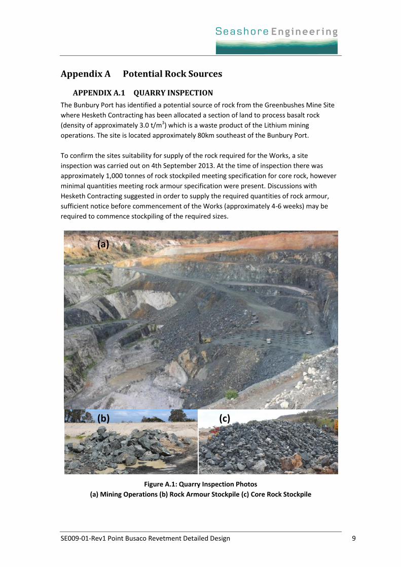
The Bunbury Port has identified a potential source of rock from the Greenbushes Mine Site
where Hesketh Contracting has been allocated a section of land to process basalt rock
(density of approximately 3.0 t/m3) which is a waste product of the Lithium mining
operations. The site is located approximately 80km southeast of the Bunbury Port.
To confirm the sites suitability for supply of the rock required for the Works, a site
inspection was carried out on 4th September 2013. At the time of inspection there was
approximately 1,000 tonnes of rock stockpiled meeting specification for core rock, however
minimal quantities meeting rock armour specification were present. Discussions with
Hesketh Contracting suggested in order to supply the required quantities of rock armour,
sufficient notice before commencement of the Works (approximately 4-6 weeks) may be
required to commence stockpiling of the required sizes.
Figure A.1: Quarry Inspection Photos
(a) Mining Operations (b) Rock Armour Stockpile (c) Core Rock Stockpile
(a)
(c) (b)
SE009-01-Rev1 Point Busaco Revetment Detailed Design 10
APPENDIX A.2 ALTERNATIVE ROCK SOURCES
The state‐owned Roelands quarry previously used to source Port development works
potentially provides the nearest suitable quarry. Although the quarry is not presently
operational, the Department of Transport is in the process of planning to evaluate the
viability of re‐establishing Roelands quarry to supply a range of local projects. Other quarries
previously known to have supplied rock to recent coastal projects in the southwest are
located at Gelorup (basalt) and Byford (granite).
SE009-01-Rev1 Point Busaco Revetment Detailed Design 11
Appendix B Drawings
Drawing No. Title
DA-2296-2-1 POINT BUSACO REVETMENT - DETAILED DESIGN
DA-2296-2-2 PROVISIONAL GROYNE - DETAILED DESIGN
CH 1
80
CH 1
60
CH 1
40
CH 1
20
CH 1
00
CH 8
0
CH 6
0
CH 4
0
CH 20
CH 00
CH 2
00
CH 23
0
CH 220
11
10
9
8
7
6
5
4
3
2
1
POINT EASTING NORTHING
34689.3
34698.3
34724.1
34739.5
34752.8
34794.5
34819.3
34832.3
34862.3
34871.3
34877.0
111738.1
111759.4
111766.0
111768.9
111770.8
111784.9
111794.5
111801.0
111821.3
111830.6
111841.8
3.5m
1.0m
0.5m
0.0m
-0.5
m
-1.0
m
2.5m
SOP 11
SOP 10
SOP 9
SOP 8 SOP 7
SOP 6
SOP 5
SOP 4
SOP 3
SOP 2
SOP 1
111800 mN 111800 mN
34600 m
E34600 m
E
34700 m
E34700 m
E
34800 m
E34800 m
E
34900 m
E34900 m
E
ROCK TYPE SIZE RANGE
(50% > 1.25t)
0.85 - 1.5t
(50% > 0.85t)
0.4 - 1.2t
(CLASS 3)
CORE
(50% > 0.3m)
0.15 - 0.5m
(CLASS 1)
TOE
(CLASS 2)
ARMOUR
ESTIMATED QUANTITIES
850t ( DENSITY 3.0t/m³)
750t ( DENSITY 2.6t/m³) or
4550t ( DENSITY 3.0t/m³)
4150t ( DENSITY 2.6t/m³) or
2200t ( DENSITY 3.0t/m³)
1950t ( DENSITY 2.6t/m³) or
1750t (DENSITY 2.3t/m³) or
BETWEEN CHAINAGE 220m - 230m
TRANSITION OF TOE LEVEL TO + 1.7m AHD AND SLOPE TO 1:3
TOE OF REVETMENT
EXPOSED ROCK
APPROXIMATE LIMIT OF
REMOVE TREE
REMOVE TREES
TOP OF BATTER SLOPE
CREST OF REVETMENT
BETWEEN CHAINAGE 25m - 40m
TRANSITION OF CREST HEIGHT FROM 2.5m TO 3.5m
ARC LENGTH = 28m
RADIUS = 16m
TELECOMUNICATION TOWER
(REFER DRG No. DA-2296-2-2)
PROVISIONAL GROYNE
A
-
-
B
NOTES
REV DATE AMENDMENT
APP
DRN
ORIG SIZE ARCHIVE
J.BARTLETT
DETAILED DESIGN
BUNBURY PORT AUTHORITY
POINT BUSACO REVETMENT
CDA-2296-2-1
G.McCORMACK 15.10.13
15.10.13
26.11.13
26.11.13
PROJECT
TITLE
DRAWING NUMBER
CHECK
DRAFTING
REV
DRAWN
ENGINEER
PROJECT MGR
APPROVED
CHECK
ENGINEERING
G.BEBBINGTON
S.BARR
CLIENT
AHD
DATUM
PCG94
VERTICAL
HORIZONTAL
Civil Drafting.
Topographic Mapping.
Marine, Cadastral &
BebbCart
3.
2.
1.
DREDGE SPOIL INCLUDING SAND, SILT AND ROCK FRAGMENTS
EXCAVATED MATERIAL IS ANTICIPATED TO LARGELY CONSIST OF
AERIAL IMAGERY; BUNBURY TOWNSITE N0V 2010
OVERLAP OF REQUIRED BETWEEN SHEETS OF GEOFABRIC IS 0.5m
2.4m
1.4
m
0.6
m
1
1.5
LEVEL VARIES
3.5m AHD
-1.0m AHD
NATURAL SURFACE VARIES
1.7m
CORE (CLASS 3)
GEOFABRIC ELCOMAX 1200R
(CLASS 1)
ARMOUR
1 5
METRES
1001 5
METRES
100
SCALE 1 : 100SCALE 1 : 100
(CLASS 2)
3 TOE ROCKS CORE (CLASS 3)
GEOFABRIC ELCOMAX 1200R
(CLASS 2)
ARMOUR
1.4
m
0.6
m
1
1.5
2.4m
-1.0m AHD
(CLASS 1)
3 TOE ROCKS
NATURAL SURFACE VARIES
LEVEL VARIES
2.5m AHD
1.7m
0.2m TO 0.4m
AND FINISHED SURFACE
CREST OF REVETMENT
VARIES BETWEEN
CRUSHED LIMESTONE
LIMESTONE
CEMENT STABILIZED
min 0.2
m
0.1m
min ARMOUR
CORE
GEOFABRIC ELCOMAX 1200R
TYPICAL SECTION A TYPICAL SECTION BSCALE 1:100 SCALE 1:100
29.10.13
10.12.13
09.04.14
A
C
ISSUED FOR CLIENT REVIEW
AMENDMENTS FROM ENGINEERING CHECK
DRAWING TRANSFORMED TO PERTH COASTAL GRID 94
JB
CJL
SJM
B
NTS
CREST DETAIL
SCALE 1 : 1000
10 0 50
METRES
A3
CH 23
0
CH 220
CH 2
00
CH 1
80
NOTES
REV DATE AMENDMENT
APP
DRN
ORIG SIZE ARCHIVE
PROJECT
TITLE
DRAWING NUMBER
CHECK
DRAFTING
REV
DRAWN
ENGINEER
PROJECT MGR
APPROVED
CHECK
ENGINEERING
CLIENT
DATUM
VERTICAL
HORIZONTAL
Civil Drafting.
Topographic Mapping.
Marine, Cadastral &
BebbCart
POINT EASTING NORTHING
500t ( DENSITY 3.0t/m³)
430t ( DENSITY 2.6t/m³) orARMOUR
CORE
(50% > 0.85t)
0.4 - 1.2t
(50% > 0.3m)
0.15 - 0.5m
250t ( DENSITY 3.0t/m³)
220t ( DENSITY 2.6t/m³) or
190t (DENSITY 2.3t/m³) or
ROCK TYPE SIZE RANGE ESTIMATED QUANTITIES
875m
0.5m
625m1875m625m
ARMOUR
CORE
SCALE 1:75
-1.0m AHD
1.3m AHD
2.0m AHD
1.5
1
TYPICAL SECTION C
(m A.H.D.)
ELEVATION
-1.0m AHD
1.5
1
2.0m AHD
ARMOUR
CORE
SCALE 1:75 SCALE 1 : 75
METRES
1 0 3
TYPICAL SECTION D
REVETMENT
POINT BUSACO
-1
2
0
1
3
4
1 2 3 4 5 6 7 8 9 10 11 12 13 14 15 16 17 18 19 200-1-2-3-4
SOP 1
SOP 2
-
-
C
D
0.5m
3.5m
BE VARIED ACCORDINGLY.
OF CONSTRUCTION. ROCK QUANTITIES TO
WIDTH MAY BE VARIED TO FACILITATE EASE
TOWER
TELECOMUNICATION
34703.1
34704.1
111766.0
111762.1
2
1
0
METRES
5 20
SCALE 1 : 500
BUNBURY PORT AUTHORITY
POINT BUSACO REVETMENT
PROVISIONAL GROYNE
DETAILED DESIGN
DA-2296-2-2 C
G.McCORMACK 15.10.13
15.10.13J.BARTLETT
G.BEBBINGTON
S.BARR
A3
29.10.13A
B
C
10.12.13
09.04.14
ISSUED FOR CLIENT REVIEW
AMENDMENTS FROM ENGINEERING CHECK CJL
JB
SJMDRAWING TRANSFORMED TO PCG94, GEOFABRICS ADDED
AERIAL IMAGERY; BUNBURY TOWNSITE NOVEMBER 20101.
SURVEYED BEACH PROFILE
GEOFABRIC OVERLAYED BY TRIAXIAL GEOGRID
ALONG GROYNE EDGES
1.0m OVERLAP OF GEOFABRIC
ALONG GROYNE EDGES
1.0m OVERLAP OF GEOFABRIC
PCG94
AHD


