Astos Solutions GmbH Grund 1, 78089 Unterkirnach, Germany
All Rights Reserved - Copyright 2013 per ISO 16016 Copying and distribution is prohibited without express authority.
AstosSolutions
1 Introduction
This document provides a detailed overview of the database used by the Pointing Error Engineering Tool (PEET). The database consists of three parts. On Java side, each block type is represented by its own Java class. This Java class is responsible for providing the block mask and for managing the pointing error calculations. On MATLAB side, each block type is also represented by its own MATLAB class, which implements the respective mathematical algorithms for the actual calculations. The third component of the database is the database definition file. This file defines all block types by name and associates all block types with the corresponding Java and MATLAB classes.
The MATLAB classes are based on the iFR Precision Analysis and Control Toolbox in MATLAB. This toolbox provides algorithms in MATLAB for the research results published in [RD3] - [RD6], but also to not yet published results. In order to integrate the toolbox in the PEET framework, it has been extended and adapted by the subcontractor iFR.
In the next chapters, the parameters required by the various block types are listed and explained in detail.
This document has been prepared for the Project “Pointing Error Engineering Tool" (PEET) performed by Astos Solutions under contract of the European Space Agency.
PEET Doc.No: ASTOS-PEET-TN-002
Issue: 1.4 Date: 2013-07-08
Page: 6 of: 34
Astos Solutions GmbH Grund 1, 78089 Unterkirnach, Germany
All Rights Reserved - Copyright 2013 per ISO 16016 Copying and distribution is prohibited without express authority.
AstosSolutions
2 Applicable and Reference Documents
2.1 Applicable Documents
[AD1] ESSB-HB-E-003; ESA Pointing Error Engineering Handbook
[RD3] Ott T., Benoit A., Van den Braembussche P., Fichter W., “ESA Pointing Error Engineering Handbook”, 8th International ESA Conference on Guidance, Navigation & Control Systems, Karlovy Vary CZ, June 2011.
[RD4] Ott T., Fichter W., Bennani S., Winkler S.‚ "Precision Pointing H∞-Control Design for Absolute-, Windowed-, and Stability-Time Errors", manuscript submitted to CEAS Space Journal.
[RD5] Hirth M., Brandt N., Fichter W., "Inertial Sensing for Future Gravity Missions", GEOTECHNOLOGIEN Science Report No.17, Observation of the System Earth from Space, Bonn, 2010, ISSN: 1619-7399.
[RD6] Hirth M., Fichter W., et al., "Optical Metrology Alignment and Impact on the Measurement Performance of the LISA Technology Package", Journal of Physics Conference Series, 7th International LISA Symposium, Barcelona, Spain, 2008
[RD7] IEEE-STD 952-1997 (R2003); IEEE Standard Specification Format Guide and Test Procedure for Single-Axis Interferometric Fiber Optic Gyros
[RD8] NPD/5022/TD/TR/001 v1.r1.m0; "Error Budgets for Formation Flying Missions", Harwood A. March 2008
[RD9] PFF-MEMO-MC-001; "Reaction Wheel Microvibration Model", Memo, Casasco M., April 2013.
[RD10] Masterson R.A., "Development and Validation of Empirical and Analytical Reaction Wheel Disturbance Models", Master Thesis, Massachussetts Institute of Technology, June 1999.P3-EST-TN-7001;
[RD11] Masterson R.A., Miller D.W., Grogan R.L. "Development of Empirical and Analytical Reaction Wheel Disturbance Models", AIAA 99-1204, AIAA Structural Dynamics and Materials Conference, St. Louis, USA, 1999.
PEET Doc.No: ASTOS-PEET-TN-002
Issue: 1.4 Date: 2013-07-08
Page: 7 of: 34
Astos Solutions GmbH Grund 1, 78089 Unterkirnach, Germany
All Rights Reserved - Copyright 2013 per ISO 16016 Copying and distribution is prohibited without express authority.
AstosSolutions
3 Terms, Definitions and Abbreviated Terms
3.1 Acronyms
The following abbreviations are used throughout this document.
Acronyms
PEET Pointing error engineering tool
PES Pointing error source
PSD Power spectral density
3.2 Definitions
The following definitions are used throughout this document.
Definitions
Signal The information about the pointing error which will be exchanged between adjacent blocks.
Block mask The input dialog provided by the blocks for parameter input.
Selection The data type selection is used for data with predefined values. The user can only select from these values.
List The data type list is used for tabular data with an unlimited number of rows The user can add as many rows as he requires.
PEET Doc.No: ASTOS-PEET-TN-002
Issue: 1.4 Date: 2013-07-08
Page: 8 of: 34
Astos Solutions GmbH Grund 1, 78089 Unterkirnach, Germany
All Rights Reserved - Copyright 2013 per ISO 16016 Copying and distribution is prohibited without express authority.
AstosSolutions
4 Database Specification and Requirements
4.1 Requirements
This section briefly summarizes general topics and requirements for the database.
4.1.1 Database Definition
The definition of the database is given by a simple text file using a XML file format. Each entry inside the database contains at least the block type name and the names of the corresponding Java and MATLAB classes. A detailed description of the database file structure is given in Chapter 5.3.3 of the ICD [RD1].
4.1.2 Database Extension
The database is extendable by the user. To add new blocks to the database, it is required to add a new entry to the database file, containing the block type name and the names of the Java and MATLAB classes. The jar file(s) containing the Java classes, used by the new block type, must be added to the static MATLAB class path. The MATLAB class files must be placed in the appropriate package folder inside the lib/classes folder of the PEET installation.
4.1.3 Parameter Compatibility
The parameters of the various block types must be compatible with MATLAB functions like tf, ss, frd, and zpk. No data conversion should be performed between the parameters of the Java classes and the parameters required by the MATLAB classes.
4.1.4 Available Block Types
The block database will provide at least the following block types:
Coordinate transformation
Dynamic system
Feedback system
Flexible plant
Gyro-Stellar estimator
Gyro rate noise
Mapping block
Pointing error source
Rigid plant
Static system
Summation
PEET Doc.No: ASTOS-PEET-TN-002
Issue: 1.4 Date: 2013-07-08
Page: 9 of: 34
Astos Solutions GmbH Grund 1, 78089 Unterkirnach, Germany
All Rights Reserved - Copyright 2013 per ISO 16016 Copying and distribution is prohibited without express authority.
AstosSolutions
5 Block Types
This chapter explains the various block types and their required parameters. For each block type, the meaning of the block parameters will be explained in detail.
If not otherwise stated in the software user manual or in the block masks, all parameters must be provided in SI units (e.g. angles must be defined in radian). It is up to the user to ensure that the numbers are consistent across the pointing system. If a block mask forces the user to provide parameters in Non-SI units, these parameters will be converted to SI units internally.
5.1 Coordinate Transformation Block
The coordinate transformation block is used to transform signal data from one coordinate system to another coordinate system. The coordinate system transformation is defined by an Euler transformation using three angles and a rotation sequence. The resulting matrix is used as static system gain to transfer the input signal.
5.1.1 Block Parameters
The coordinate transformation parameters offered by the block mask are listed in the following table.
Block mask parameters
Rotation sequence Selection The rotation sequence used for the Euler transformation.
Possible values are 1-2-3, 1-3-2, 2-1-3, 2-3-1, 3-1-2, 3-2-1, 1-2-1, 1-3-1, 2-1-2, 2-3-2,
3-1-3 and 3-2-3.
Phi Double The angle describing the rotation around the first axis of the rotation sequence.
Theta Double The angle describing the rotation around the second axis of the rotation sequence.
Psi Double The angle describing the rotation around the third axis of the rotation sequence.
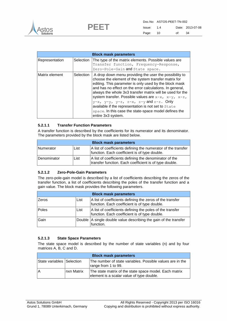
5.2 Dynamic System Block
The dynamic system block is used to model any kind of dynamic systems. In general, the system transfer is described by a 3x3 matrix. The elements of the system transfer matrix can be transfer functions, frequency-response models or zero-pole-gain models. Alternatively a state space model can be provided which defines the dynamic system. Internally all inputs are transformed to a state space model which will be used for the system transfer.
5.2.1 Block Parameters
Depending on the matrix element type, different parameters are provided by the block mask as described in the next subchapters. The two parameters which are always available independent of the matrix element type are listed in the next table.
PEET Doc.No: ASTOS-PEET-TN-002
Issue: 1.4 Date: 2013-07-08
Page: 10 of: 34
Astos Solutions GmbH Grund 1, 78089 Unterkirnach, Germany
All Rights Reserved - Copyright 2013 per ISO 16016 Copying and distribution is prohibited without express authority.
AstosSolutions
Block mask parameters
Representation Selection The type of the matrix elements. Possible values are Transfer function, Frequency-Response,
Zero-Pole-Gain and State space.
Matrix element Selection A drop down menu providing the user the possibility to choose the element of the system transfer matrix for editing. This parameter is only used by the block mask and has no effect on the error calculations. In general, always the whole 3x3 transfer matrix will be used for the
system transfer. Possible values are x-x, x-y, x-z,
y-x, y-y, y-z, z-x, z-y and z-z. Only
available if the representation is not set to State
space. In this case the state-space model defines the
entire 3x3 system.
5.2.1.1 Transfer Function Parameters
A transfer function is described by the coefficients for its numerator and its denominator. The parameters provided by the block mask are listed below.
Block mask parameters
Numerator List A list of coefficients defining the numerator of the transfer function. Each coefficient is of type double.
Denominator List A list of coefficients defining the denominator of the transfer function. Each coefficient is of type double.
5.2.1.2 Zero-Pole-Gain Parameters
The zero-pole-gain model is described by a list of coefficients describing the zeros of the transfer function, a list of coefficients describing the poles of the transfer function and a gain value. The block mask provides the following parameters.
Block mask parameters
Zeros List A list of coefficients defining the zeros of the transfer function. Each coefficient is of type double.
Poles List A list of coefficients defining the poles of the transfer function. Each coefficient is of type double.
Gain Double A single double value describing the gain of the transfer function.
5.2.1.3 State Space Parameters
The state space model is described by the number of state variables (n) and by four matrices A, B, C and D.
Block mask parameters
State variables Selection The number of state variables. Possible values are in the range from 1 to 99.
A nxn Matrix The state matrix of the state space model. Each matrix element is a scalar value of type double.
PEET Doc.No: ASTOS-PEET-TN-002
Issue: 1.4 Date: 2013-07-08
Page: 11 of: 34
Astos Solutions GmbH Grund 1, 78089 Unterkirnach, Germany
All Rights Reserved - Copyright 2013 per ISO 16016 Copying and distribution is prohibited without express authority.
AstosSolutions
B Nx3 Matrix The input matrix of the state space model. Each matrix element is a scalar value of type double.
C 3xn Matrix The output matrix of the state space model. Each matrix element is a scalar value of type double.
D 3x3 Matrix The feedthrough matrix of the state space model. Each matrix element is a scalar value of type double.
5.3 Feedback System Block
Feedback systems are the only block type which allows the user to integrate loops into the pointing system. The fixed structure of the feedback system implemented by this block type is shown in Figure 5-1.
Figure 5-1: Feedback system structure
Each of the blocks labelled 1 to 6 can either be turned on or off. If turned on, the user has to specify the block type and the block parameters. The available block types are a subset of the blocks available in the database and are explained in chapter 5.3.1. By turning internal blocks on and off, the user can build up any kind of feedback system structure required for the pointing error calculations of PEET.
The nodes labelled A to G serves as input or output ports. It is possible to define more than one input port. The number of output ports is restricted to one. In addition to this restriction, it is not possible to use one of the nodes as input and output port.
All block parameters are converted internally to state space models. Using this state space models, an equivalent dynamic system is build up which will be used for the system transfer.
5.3.1 Block Parameters
The parameters for the feedback system can be divided into two groups. The first set of parameters deals with the definition of the input and output ports. These parameters are listed in the next table.
Block mask parameters
Input ports Selection The user can choose one or more input ports. Possible
values are A, B, C, D, E, F and G. The node which is
currently set as output port cannot be selected as input port.
PEET Doc.No: ASTOS-PEET-TN-002
Issue: 1.4 Date: 2013-07-08
Page: 12 of: 34
Astos Solutions GmbH Grund 1, 78089 Unterkirnach, Germany
All Rights Reserved - Copyright 2013 per ISO 16016 Copying and distribution is prohibited without express authority.
AstosSolutions
Output port Selection The user can select the output port. Only one node can be
set as output port. Possible values are A, B, C, D, E,
F and G. If the user selects a node which is currently used
as input port, this port is removed from the list of input ports and set as the one and only output port.
The second set of parameters deals with the parameter settings for the blocks. Each of the blocks provides the same parameters which are listed below. In general any system transfer block from the database can be selected with the only restriction of one single 3D input and one single 3D output.
Block mask parameters
Block type Selection The type of the block. Possible values are Unused, Coordinate Transformation, Dynamic System,
Flexible Plant, Rigid Plant, Static System
and PID Controller.
Using the block type Unused turns off the block. By turning off a block, the signal can
pass this block without any modifications to it. If a block type different than Unused is
selected, additional parameters are available. These parameters are described in the next chapters.
The parameters for the coordinate transformation type are the same as for the Coordinate Transformation block. These parameters are explained in detail in chapter 5.1.
5.3.1.2 Internal Block Type: Dynamic System
The parameters for the dynamic system type are the same as for the Dynamic System block. These parameters are explained in detail in chapter 5.2.
5.3.1.3 Internal Block Type: Flexible Plant
The parameters for the flexible plant type are the same as for the Flexible Plant block. These parameters are explained in detail in chapter 5.4.
5.3.1.4 Internal Block Type: Rigid Plant
The parameters for the rigid plant type are the same as for the Rigid Plant block. These parameters are explained in detail in chapter 5.11.
5.3.1.5 Internal Block Type: Static System
The parameters for the static system type are the same as for the Static System block. These parameters are explained in detail in chapter 5.13.
5.3.1.6 Internal Block Type: PID Controller
The parameters for the PID controller system type are the same as for the PID Controller block. These parameters are explained in detail in chapter 5.12.
PEET Doc.No: ASTOS-PEET-TN-002
Issue: 1.4 Date: 2013-07-08
Page: 13 of: 34
Astos Solutions GmbH Grund 1, 78089 Unterkirnach, Germany
All Rights Reserved - Copyright 2013 per ISO 16016 Copying and distribution is prohibited without express authority.
AstosSolutions
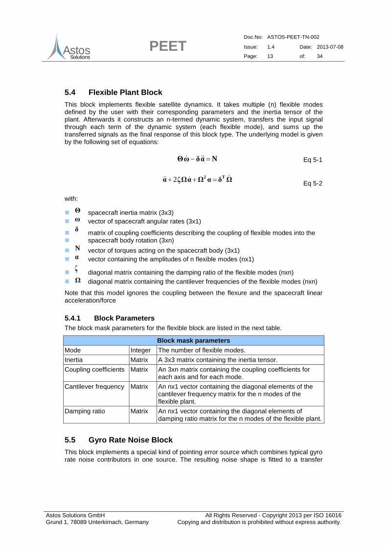
5.4 Flexible Plant Block
This block implements flexible satellite dynamics. It takes multiple (n) flexible modes defined by the user with their corresponding parameters and the inertia tensor of the plant. Afterwards it constructs an n-termed dynamic system, transfers the input signal through each term of the dynamic system (each flexible mode), and sums up the transferred signals as the final response of this block type. The underlying model is given by the following set of equations:
NαδωΘ Eq 5-1
ΩδαΩαΩζα
T2 2 Eq 5-2
with:
Θ spacecraft inertia matrix (3x3)
ω vector of spacecraft angular rates (3x1)
δ
matrix of coupling coefficients describing the coupling of flexible modes into the spacecraft body rotation (3xn)
N vector of torques acting on the spacecraft body (3x1)
α vector containing the amplitudes of n flexible modes (nx1)
ζ
diagonal matrix containing the damping ratio of the flexible modes (nxn)
Ω diagonal matrix containing the cantilever frequencies of the flexible modes (nxn)
Note that this model ignores the coupling between the flexure and the spacecraft linear acceleration/force
5.4.1 Block Parameters
The block mask parameters for the flexible block are listed in the next table.
Block mask parameters
Mode Integer The number of flexible modes.
Inertia Matrix A 3x3 matrix containing the inertia tensor.
Coupling coefficients Matrix An 3xn matrix containing the coupling coefficients for each axis and for each mode.
Cantilever frequency Matrix An nx1 vector containing the diagonal elements of the cantilever frequency matrix for the n modes of the flexible plant.
Damping ratio Matrix An nx1 vector containing the diagonal elements of damping ratio matrix for the n modes of the flexible plant.
5.5 Gyro Rate Noise Block
This block implements a special kind of pointing error source which combines typical gyro rate noise contributors in one source. The resulting noise shape is fitted to a transfer
PEET Doc.No: ASTOS-PEET-TN-002
Issue: 1.4 Date: 2013-07-08
Page: 14 of: 34
Astos Solutions GmbH Grund 1, 78089 Unterkirnach, Germany
All Rights Reserved - Copyright 2013 per ISO 16016 Copying and distribution is prohibited without express authority.
AstosSolutions
function with user-specified parameters and mapped to all axes (x,y and z) assuming no correlation between the axes.
5.5.1 Block Parameters
The GUI parameters for the gyro rate noise block are shown in the table below.
Block mask parameters
Min. pole order Double Minimum pole order for rational fit of PSD
Max. pole order Double Maximum pole order for rational fit of PSD
Number of frequency points
Double Frequency point used for rational fitting
Angle random walk (N) Double The magnitude of the angle random walk [°/√h].
Rate random walk (K) Double The magnitude of the angle random walk [°/h3/2
].
Bias instability (B) Double The magnitude of the bias instability [°/h].
Quantization noise (Q) Double The magnitude of the quantization noise [arcsec].
Time window (T) Double The time window [s].
Using the parameters defined, the Gyro Rate Noise block realizes a PSD type error source with a spectral behaviour as shown in Figure 5-2. For further information about the involved parameters see appendix B of [RD7].
This block implements the gyro-stellar estimator in PEET. It is the only block type which has more than one output port. The parameters required by this block type are the two Kalman gains Kp and Kd. In general, the Kalman estimator is realized as a dynamic system, which takes 3 inputs and 2 outputs. It computes the signal transfer according to the fixed Kalman estimator structure using user input gains from the model given below individually for each axis:
PEET Doc.No: ASTOS-PEET-TN-002
Issue: 1.4 Date: 2013-07-08
Page: 15 of: 34
Astos Solutions GmbH Grund 1, 78089 Unterkirnach, Germany
All Rights Reserved - Copyright 2013 per ISO 16016 Copying and distribution is prohibited without express authority.
AstosSolutions
gyropgyrodStrd
gyrogyroStrdp
2p
2 B)Ks(nKnsK
Bnsn)KsK(
KsKs
1
B~φ~
Eq 5-3
5.6.1 Block Parameters
The GUI parameters for the gyro-stellar estimator block are listed in the next table.
Block mask parameters
Kalman gain Kp Vector A three dimensional vector containing the Kalman gains Kp for the x,y and z axis. The elements of the vector are of type double.
Kalman gain Kd Vector A three dimensional vector containing the Kalman gains Kd for the x,y and z axis. The elements of the vector are of type double.
5.6.2 Block inputs and outputs
The gyro-stellar estimator block offers the user three input and two output ports. All of these ports are optional and can be left unconnected. An explanation of these ports is provided by the tables below.
Input ports
n_str The star-tracker measurement noise.
n_gyro The gyro rate measurement noise.
b_gyro The gyro drift bias noise ('Rate random walk').
Output ports
φ_est The attitude estimation error.
B_est The gyro bias estimation error
Note the gyro noise contributions can be realized in different ways: Either as individual signals using both n_gyro and b_gyro or by combining the gyro drift bias and rate noise to a total noise using the Gyro Rate Noise block presented in section 5.5 only and feeding it to the n_gyro input only (see also definition of PES 7 in the PointingSat example for further details).
5.7 Mapping Block
The Mapping block is used to map a 1D signal to a spatially distributed 3D signal, i.e. mapping thruster noise from the axis of each thruster to the reference frame of the pointing error. The user input consists of the number of devices (n) that are mapped by this block and the nx3 mapping matrix. The mapping block extends the 1D signal to an nxn signal, and transfers the nxn signal through the nx3 mapping matrix, which serves as a static system. Finally it produces a three dimensional signal.
5.7.1 Block Parameters
The next table explains the block mask parameters for the Mapping block.
PEET Doc.No: ASTOS-PEET-TN-002
Issue: 1.4 Date: 2013-07-08
Page: 16 of: 34
Astos Solutions GmbH Grund 1, 78089 Unterkirnach, Germany
All Rights Reserved - Copyright 2013 per ISO 16016 Copying and distribution is prohibited without express authority.
AstosSolutions
Block mask parameters
Number of devices Selection The number of devices which will be mapped by this block. Possible values are in the range from 1 to 99.
Mapping matrix Matrix The nx3 mapping matrix with as many rows as devices are defined. The columns contain the mappings for the x, y and z axis.
5.8 PEC Blocks
The pointing error contributor block represents the "endpoint" of each PEET system model at which the resulting total error contribution shall be evaluated. The evaluation is realized according to AST-4 of [AD1] and the results are grouped into time-constant, time-random and total error contribution. The usage of a PEC block is mandatory for each PEET system and only one PEC block can be used in a system. Two kinds of blocks are available in the block database:
5.8.1 PEC (Pointing)
The PEC (Pointing) block is the standard block for the overall error evaluation. It has no parameters and only one single input which corresponds to the total error signal of the system under consideration. The content of the different parts of the input signal (CRV, RV, drift, periodic signal and random process part) is summed according to AST-4 of [AD1] after the equivalent variance of a potential random process signal is computed within the user-defined global evaluation bandwidth.
The overall error is computed per axis (x,y,z) and with respect to the user defined LOS axis. Note that the latter is the only special feature that links the block really to pointing. Disregarding the LOS error, this block (and PEET) could be used to compute any kind of 3-axis budget (i.e. PEET could generally be understood as "Performance Error Engineering Tool" rather than a "Pointing Error Engineering Tool" only.
5.8.2 PEC (Position)
The PEC (Position) realizes a special case for the overall error evaluation. It allows the computation of a position/displacement error budget which is the result of "pure" 3-axis position errors and 3-axis attitude errors which couple into equivalent position errors due to dedicated "lever arms" (e.g. as it is the case for formation flying missions such as PROBA 3). The implemented model is based on Eq.5 in [RD8] (Note the summation of absolute values for the means. This is intentionally different to [RD8] to achieve a more conservative result in case sign relations are not exactly known a priori):
attatt
attatt
attatt
N
1i
2
i,x,att
2
i
2
i.y,att
2
i
2
z,pos
2
z,tot
N
1i
i,x,attii,z,attiz,posz,tot
N
1i
2
i,z,att
2
i
2
i.x,att
2
i
2
y,pos
2
y,tot
N
1ii,z,attii,z,attiy,posy,tot
N
1i
2
i,y,att
2
i
2
i.z,att
2
i
2
x,pos
2
x,tot
N
1i
i,y,attii,z,attix,posx,tot
σyσxσσμyμxμμ
σxσzσσμxμzμμ
σzσyσσμzμyμμ
Eq 5-4
with (axis index omitted):
PEET Doc.No: ASTOS-PEET-TN-002
Issue: 1.4 Date: 2013-07-08
Page: 17 of: 34
Astos Solutions GmbH Grund 1, 78089 Unterkirnach, Germany
All Rights Reserved - Copyright 2013 per ISO 16016 Copying and distribution is prohibited without express authority.
AstosSolutions
totμ total mean of resulting displacement error
totσ total standard deviation of resulting displacement error
posμ overall mean of "pure" position error contributors
posσ overall standard deviation of "pure" position error contributors
attN number of attitude error coupling to position
i,attμ mean of i-th attitude error
i,attσ standard deviation of i-th attitude error
iii z,y,x components of coupling vector of i-th attitude error
Different to Eq. 5 in [RD8] there is no summation over different position error contributors. The summation of these contributors has to be realized using standard Sum blocks in the PEET system (this allows the usage of one single position error input for the PEC (Position) block). The number of additional block inputs for the attitude errors depends on the settings of the parameters which are listed in the table below:
Block mask parameters
Number of attitude contributors
Selection The number of attitude contributors (Natt) that couple with different lever arms to position errors (determines the number of additional block input ports).
Attitude coupling vector
Matrix Nattx3 mapping matrix with as many rows as attitude contributors are defined. The columns contain the x, y and z components of the i-th coupling vector.
The tree-view of the block finally provides the following information:
signal content of each attitude and position error signals the total mean and standard deviation of the resulting displacement error (time-
constant, time-random and overall contribution) the mean and standard deviation of the "pure" position error contributor only (time-
constant, time-random and overall contribution) the mean and standard deviation of the position error due to all the attitude
contributors only (time-constant, time-random and overall contribution)
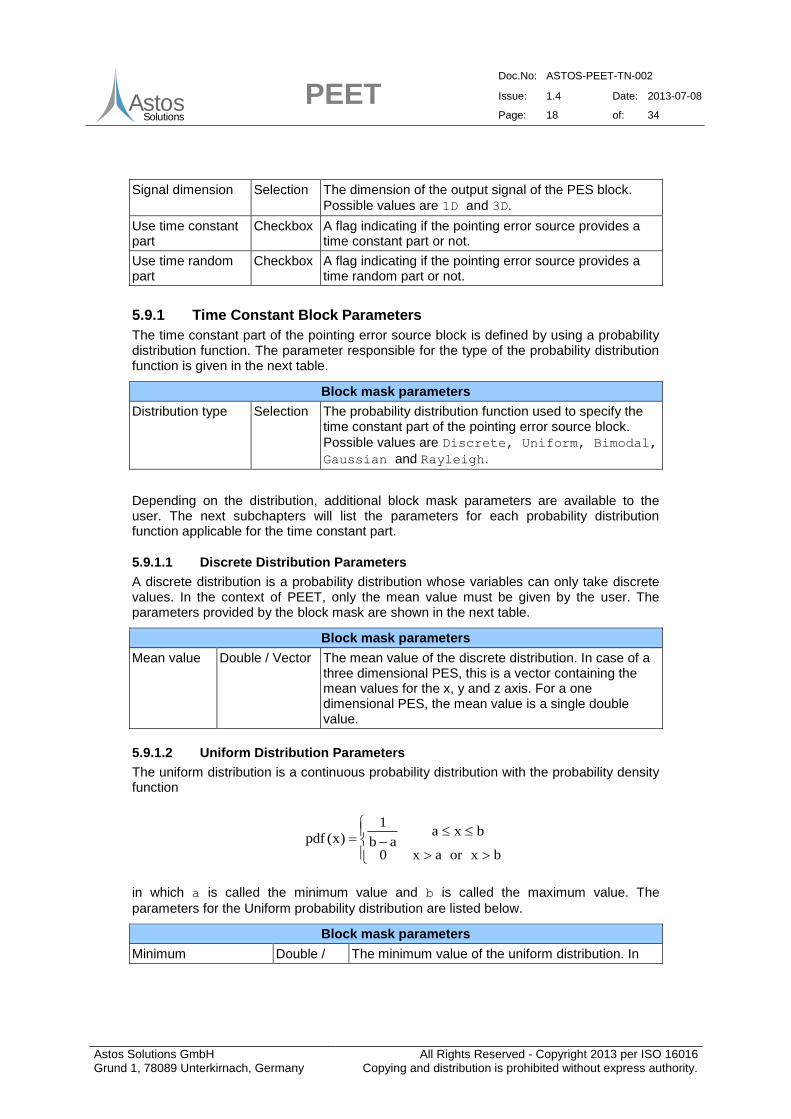
5.9 PES Block
The pointing error source block is used to model all kind of error sources applicable to pointing error calculations. Each pointing error source consists of a time constant part and a time random part. The time constant part is defined by a probability distribution function. The time random part is either defined as a random variable or as a random process. Internally, the time constant part and the time random part of type random variable are converted to an equivalent Gaussian distribution. If the time random part is described as a random process, it is converted to a state space representation. The signal generated by a pointing error source block can either be one dimensional or three dimensional. The dimension of the signal is set by the parameter listed in the table below. The dimension applies to the time constant part as well as to the time random part.
Block mask parameters
PEET Doc.No: ASTOS-PEET-TN-002
Issue: 1.4 Date: 2013-07-08
Page: 18 of: 34
Astos Solutions GmbH Grund 1, 78089 Unterkirnach, Germany
All Rights Reserved - Copyright 2013 per ISO 16016 Copying and distribution is prohibited without express authority.
AstosSolutions
Signal dimension Selection The dimension of the output signal of the PES block.
Possible values are 1D and 3D.
Use time constant part
Checkbox A flag indicating if the pointing error source provides a time constant part or not.
Use time random part
Checkbox A flag indicating if the pointing error source provides a time random part or not.
5.9.1 Time Constant Block Parameters
The time constant part of the pointing error source block is defined by using a probability distribution function. The parameter responsible for the type of the probability distribution function is given in the next table.
Block mask parameters
Distribution type Selection The probability distribution function used to specify the time constant part of the pointing error source block.
Possible values are Discrete, Uniform, Bimodal,
Gaussian and Rayleigh.
Depending on the distribution, additional block mask parameters are available to the user. The next subchapters will list the parameters for each probability distribution function applicable for the time constant part.
5.9.1.1 Discrete Distribution Parameters
A discrete distribution is a probability distribution whose variables can only take discrete values. In the context of PEET, only the mean value must be given by the user. The parameters provided by the block mask are shown in the next table.
Block mask parameters
Mean value Double / Vector The mean value of the discrete distribution. In case of a three dimensional PES, this is a vector containing the mean values for the x, y and z axis. For a one dimensional PES, the mean value is a single double value.
5.9.1.2 Uniform Distribution Parameters
The uniform distribution is a continuous probability distribution with the probability density function
bxorax0
bxaab
1
)x(pdf
in which a is called the minimum value and b is called the maximum value. The
parameters for the Uniform probability distribution are listed below.
Block mask parameters
Minimum Double / The minimum value of the uniform distribution. In
PEET Doc.No: ASTOS-PEET-TN-002
Issue: 1.4 Date: 2013-07-08
Page: 19 of: 34
Astos Solutions GmbH Grund 1, 78089 Unterkirnach, Germany
All Rights Reserved - Copyright 2013 per ISO 16016 Copying and distribution is prohibited without express authority.
AstosSolutions
Vector case of a three dimensional PES, this is a vector containing the minimum values for the x, y and z axis. For a one dimensional PES, the minimum value is a single double value.
Maximum Double / Vector
The maximum value of the uniform distribution. In case of a three dimensional PES, this is a vector containing the maximum values for the x, y and z axis. For a one dimensional PES, the maximum value is a single double value.
Axes correlation String The correlation between the axes. Possible values
are Uncorrelated and Full correlated. Only
available in case of a three dimensional PES.
5.9.1.3 Bimodal Distribution Parameters
The bimodal distribution is a continuous probability distribution with two modes. The modes appear as two distinct peaks (local maxima) in the probability density function. In the context of PEET it is sufficient to only specify the amplitude of the local maxima. All parameters required by the block mask are shown in the next table.
Block mask parameters
Amplitude Double / Vector The amplitude of the bimodal distribution. In case of a three dimensional PES, this is a vector containing the amplitudes for the x, y and z axis. For a one dimensional PES, the amplitude is a single double value.
Axes correlation
String The correlation between the axes. Possible values are
Uncorrelated and Full correlated. Only available
in case of a three dimensional PES.
5.9.1.4 Gaussian Distribution Parameters
The Gaussian distribution is a continuous probability distribution with the probability density function
2
σ
μx
2
1
eπ2σ
1)x(pdf
in which µ is called mean value, σ is called standard deviation and σ2
is called variance.
The block mask parameters offered by the PES block are listed below.
Block mask parameters
Mean value Double / Vector The mean value for the Gaussian distribution. In case of a three dimensional PES, this is a vector containing the mean values for the x, y and z axis. For a one dimensional PES, the mean value is a single double value.
Standard deviation
Double / Vector The standard deviation for the Gaussian distribution. In case of a three dimensional PES, this is a vector containing the standard deviation for the x, y and z axis. For a one dimensional PES,
PEET Doc.No: ASTOS-PEET-TN-002
Issue: 1.4 Date: 2013-07-08
Page: 20 of: 34
Astos Solutions GmbH Grund 1, 78089 Unterkirnach, Germany
All Rights Reserved - Copyright 2013 per ISO 16016 Copying and distribution is prohibited without express authority.
AstosSolutions
the standard deviation is a single double value.
Axes correlation String The correlation between the axes. Possible values
are Uncorrelated and Full correlated.
Only available in case of a three dimensional PES.
In case of a three dimensional PES, a 3x3 covariance matrix is always used in addition to the mean value. To simplify the user input, the user can specify the correlation between the axes. For an uncorrelated or a fully correlated PES, it is required to only define the standard deviations for the x, y and z axis. These standard deviations are used to compute the diagonal elements of the covariance matrix. Internally all other elements of the covariance matrix are set automatically to 0 for an uncorrelated PES and 1 for a fully correlated PES.
5.9.1.5 Rayleigh Distribution Parameter
The Rayleigh distribution is a continuous probability distribution with the probability density function
0σ,0x,eσ
x)x(pdf
2
2
σ2
x
2
in which σ is called the Rayleigh parameter. The parameters provided by the block mask
are listed in the next table.
Block mask parameters
Rayleigh parameter Double / Vector The Rayleigh parameter of the Rayleigh distribution. In case of a three dimensional PES, this is a vector containing the Rayleigh parameter for the x, y and z axis. For a one dimensional PES, the parameter is a single double value.
Axes correlation String The correlation between the axes. Possible
values are Uncorrelated and Full
correlated. Only available in case of a three
dimensional PES.
5.9.2 Time Random Block Parameters
The time random part of the pointing error source can either be defined as a random variable or as a random process.
If the time random part is defined as a random variable, the user has to choose from a list
of probability distributions. Possible values are Uniform, Gaussian and Drift. For
the Uniform distribution, the parameters are the same as for the time constant part. The remaining parameters for random variable options are described in chapters 5.9.2.1 and 5.9.2.2
Note that whenever a non-zero mean of a Gaussian RV is defined, PEET automatically maps this mean to a CRV with discrete distribution and removes it from the RV as it essentially represents a time-constant part. The same is true for a uniform RV (e.g. in
PEET Doc.No: ASTOS-PEET-TN-002
Issue: 1.4 Date: 2013-07-08
Page: 21 of: 34
Astos Solutions GmbH Grund 1, 78089 Unterkirnach, Germany
All Rights Reserved - Copyright 2013 per ISO 16016 Copying and distribution is prohibited without express authority.
AstosSolutions
case of a lower bound 0 and upper bound 3, a CRV with a mean of 1.5 is automatically created).
If the time random part is defined as a random process, the user has to set the type of the
random process. Possible types are Time series, PSD, Covariance and
Periodic. The parameters for these types are explained in the chapters 5.9.2.3 to
5.9.2.6
5.9.2.1 Random Variable: Gaussian Distribution Parameters
The parameters for the Gaussian distribution of the time random part are listed in the table below.
Block mask parameters
Mean value Double / Vector
In case of a three dimensional PES, this is a vector containing the mean values for the x, y and z axis. For a one dimensional PES, the parameter is a single double value.
Distribution of standard deviation
Selection The ensemble distribution of the standard
deviation. Possible values are Discrete and
Uniform.
Standard deviation Double / Matrix
A 3x1 vector defining the standard deviation for all axes. In case of a one dimensional error source the standard deviation is a scalar value. Only available if the distribution of the standard
deviation is set to Discrete.
Minimum Double / Matrix
A 3x1 vector defining the minimum standard deviation for all axes. In case of a one dimensional error source the minimum standard deviation is a scalar value. Only available if the distribution of
the standard deviation is set to Uniform.
Maximum Double / Matrix
A 3x1 vector defining the maximum standard deviation for all axes. In case of a one dimensional error source the maximum standard deviation is a scalar value. Only available if the distribution of
the standard deviation is set to Uniform.
Axes correlation String The correlation between the axes. Possible values
are Uncorrelated and Full correlated.
Only available in case of a three dimensional PES.
5.9.2.2 Random Variable: Drift Distribution Parameters
The drift distribution is only available for the time random part. The parameters provided by the block mask are listed in the table below.
Block mask parameters
Reset time Double The time after which the drift will be reset.
Rate distribution Selection A probability distribution used for the drift rate.
Possible values are Discrete, Uniform,
Gaussian and Bimodal.
PEET Doc.No: ASTOS-PEET-TN-002
Issue: 1.4 Date: 2013-07-08
Page: 22 of: 34
Astos Solutions GmbH Grund 1, 78089 Unterkirnach, Germany
All Rights Reserved - Copyright 2013 per ISO 16016 Copying and distribution is prohibited without express authority.
AstosSolutions
Axes correlation String The correlation between the axes. Possible
values are Uncorrelated and Full
correlated. Only available in case of a three
dimensional PES.
Depending on the rate distribution, additional parameters are available in the block mask. These additional parameters are explained below.
Discrete Rate Distribution
The parameters for the discrete rate distribution are shown in the next table.
Block mask parameters
Rate Double / Vector The drift rate. In case of a three dimensional PES, this is a vector containing the drift rates for the x, y and z axis. For a one dimensional PES, the parameter is a single double value.
Uniform Rate Distribution
The table below list all parameters available for the uniform rate distribution.
Block mask parameters
Minimum rate Double / Vector The minimum drift rate. In case of a three dimensional PES, this is a vector containing the minimum drift rates for the x, y and z axis. For a one dimensional PES, the parameter is a single double value.
Maximum rate Double / Vector The maximum drift rate. In case of a three dimensional PES, this is a vector containing the maximum drift rates for the x, y and z axis. For a one dimensional PES, the parameter is a single double value.
Gaussian Rate Distribution
The parameters provided by the block mask for the Gaussian rate distribution are listed below.
Block mask parameters
Mean rate Double / Vector The mean drift rate. In case of a three dimensional PES, this is a vector containing the mean drift rates for the x, y and z axis. For a one dimensional PES, the parameter is a single double value.
Standard deviation Double / Matrix The standard deviation of the drift rate. In case of a three dimensional PES, 3x1 vector containing the standard deviations and the standard deviations. For a one dimensional PES, the variance is a single double value.
PEET Doc.No: ASTOS-PEET-TN-002
Issue: 1.4 Date: 2013-07-08
Page: 23 of: 34
Astos Solutions GmbH Grund 1, 78089 Unterkirnach, Germany
All Rights Reserved - Copyright 2013 per ISO 16016 Copying and distribution is prohibited without express authority.
AstosSolutions
Bimodal Rate Distribution
Only one single parameter is required for the bimodal rate distribution. This parameter is explained below.
Block mask parameters
Amplitude Double / Vector The amplitude for a bimodal drift distribution. In case of a three dimensional PES, this is a vector containing the amplitudes for the x, y and z axis. For a one dimensional PES, the parameter is a single double value.
5.9.2.3 Random Process: Time Series Parameters
In case the time random part is defined as a random process of type Time series, the
block mask provides a single table containing time-value data. For each time step, a new row must be added to this table, which contains the time and the data values for the x, y and z axis at this time point. The time series are then converted to equivalent spectrum magnitudes (auto- and cross-spectra) first. This frequency-magnitude data is fitted to a rational transfer function in a subsequent step.
Block mask parameters
Min. pole order Double The minimum order used for the rational fit of the retrieved PSD (optional)
Max. pole order Double The maximum order used for the rational fit of the retrieved PSD (optional)
Time series List A list of time-value pairs containing the time and the data values for the x, y, and z axis. In case of a 1D signal, only a single data value must be provided.
5.9.2.4 Random Process: PSD Parameters
For the random process of type PSD, the user has to specify a either a 3x3 matrix in which the elements can either be transfer functions, frequency-response models or zero-pole-gain models or he has to specify a state space model. The parameters for the PSD type are similar to the parameters of the dynamic system block. For an explanation of the parameters see chapter 5.2.1.
In addition to these PSD representations, the user can also select Spectrum
magnitude as PSD representation. In this case the following parameters are available.
Spectrum magnitude parameters
Frequency-Magnitude List A list specifying frequency-magnitude data. In case of a three dimensional PES, a magnitude for all three axes must be provided for all frequency points. For a 1D signal, only one magnitude at each frequency point is required.
Axes correlation Selection The correlation between the axes. Possible
values are Uncorrelated an Fully correlated
PEET Doc.No: ASTOS-PEET-TN-002
Issue: 1.4 Date: 2013-07-08
Page: 24 of: 34
Astos Solutions GmbH Grund 1, 78089 Unterkirnach, Germany
All Rights Reserved - Copyright 2013 per ISO 16016 Copying and distribution is prohibited without express authority.
AstosSolutions
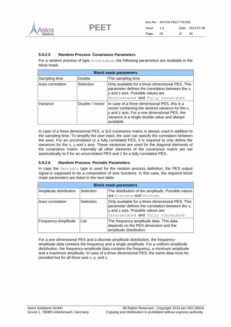
5.9.2.5 Random Process: Covariance Parameters
For a random process of type Covariance, the following parameters are available in the
block mask.
Block mask parameters
Sampling time Double The sampling time
Axes correlation Selection Only available for a three dimensional PES. This parameter defines the correlation between the x, y and z axis. Possible values are
Uncorrelated and Fully correlated
Variance Double / Vector In case of a three dimensional PES, this is a vector containing the desired variance for the x, y and z axis. For a one dimensional PES, the variance is a single double value and always available.
In case of a three dimensional PES, a 3x3 covariance matrix is always used in addition to the sampling time. To simplify the user input, the user can specify the correlation between the axes. For an uncorrelated or a fully correlated PES, it is required to only define the variances for the x, y and z axis. These variances are used for the diagonal elements of the covariance matrix. Internally all other elements of the covariance matrix are set automatically to 0 for an uncorrelated PES and 1 for a fully correlated PES.
5.9.2.6 Random Process: Periodic Parameters
In case the Periodic type is used for the random process definition, the PES output
signal is supposed to be a composition of sine functions. In this case, the required block mask parameters are listed in the next table.
Block mask parameters
Amplitude distribution Selection The distribution of the amplitude. Possible values
are Discrete and Uniform.
Axes correlation Selection Only available for a three dimensional PES. This parameter defines the correlation between the x, y and z axis. Possible values are
Uncorrelated and Fully correlated
Frequency-Amplitude List The frequency amplitude data. This data depends on the PES dimension and the amplitude distribution.
For a one dimensional PES and a discrete amplitude distribution, the frequency-amplitude data contains the frequency and a single amplitude. For a uniform amplitude distribution, the frequency-amplitude data contains the frequency, a minimum amplitude and a maximum amplitude. In case of a three dimensional PES, the same data must be provided but for all three axis x, y, and z.
PEET Doc.No: ASTOS-PEET-TN-002
Issue: 1.4 Date: 2013-07-08
Page: 25 of: 34
Astos Solutions GmbH Grund 1, 78089 Unterkirnach, Germany
All Rights Reserved - Copyright 2013 per ISO 16016 Copying and distribution is prohibited without express authority.
AstosSolutions
5.10 Reaction Wheel Model
PEET provides two special pointing error source blocks for setting up disturbance forces and torques on the spacecraft interface which are generated by a single reaction wheel. The output disturbance is always provided with respect to the wheel frame (defined by wheel spin around z-axis). The orientation of the wheel in the spacecraft/reference frame can be realized with the Coordinate Transformation PEET block, multiple wheels by repeated usage of this block. The implemented models are based on [RD9] (which are further based on [RD10] and [RD11]) and briefly explained in the following subsections.
5.10.1 Reaction Wheel (Force)
The disturbance force model includes models for the radial and axial translation mode of the wheel and covers different kinds of parameter sets for the excitation force inputs. The definition of axial force parameters is optional.
5.10.1.1 Radial Force Model
The radial (wheel x-y plane) disturbance forces acting on the spacecraft interface are modelled using the set of equations described below:
r
r
r
r
r
y
x
k0
0k
y
x
c0
0c
y
x
m0
0mF
Eq 5-5
mfπξ4c rrr Eq 5-6
2
rr )fπ2(mk Eq 5-7
y
x
k0
0k
r
r
SC,rF Eq 5-8
with:
m flywheel mass
rF the (x,y) excitation forces for the radial translation mode
rξ damping of the radial translation mode
rf frequency of the radial translation mode
SC,rF resulting (x,y) disturbance forces at the spacecraft interface
5.10.1.2 Axial Force Model
The axial (wheel z-axis) disturbance forces acting on the spacecraft interface are modelled using the set of equations described below:
aaa Fzkzczm Eq 5-9
PEET Doc.No: ASTOS-PEET-TN-002
Issue: 1.4 Date: 2013-07-08
Page: 26 of: 34
Astos Solutions GmbH Grund 1, 78089 Unterkirnach, Germany
All Rights Reserved - Copyright 2013 per ISO 16016 Copying and distribution is prohibited without express authority.
AstosSolutions
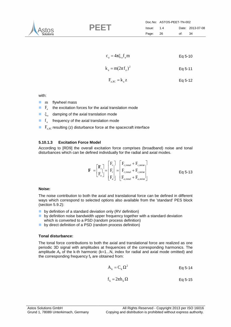
mfπξ4c aaa Eq 5-10
2
aa )fπ2(mk Eq 5-11
zkF aSC,a Eq 5-12
with:
m flywheel mass
aF the excitation forces for the axial translation mode
aξ damping of the axial translation mode
af frequency of the axial translation mode
SC,aF resulting (z) disturbance force at the spacecraft interface
5.10.1.3 Excitation Force Model
According to [RD9] the overall excitation force comprises (broadband) noise and tonal disturbances which can be defined individually for the radial and axial modes.
noise,atonal,a
noise,rtonal,r
noise,rtonal,r
a
r
r
a
r
FF
FF
FF
F
F
F
F
FF Eq 5-13
Noise:
The noise contribution to both the axial and translational force can be defined in different ways which correspond to selected options also available from the 'standard' PES block (section 5.9.2):
by definition of a standard deviation only (RV definition) by definition noise bandwidth upper frequency together with a standard deviation
which is converted to a PSD (random process definition) by direct definition of a PSD (random process definition)
Tonal disturbance:
The tonal force contributions to both the axial and translational force are realized as one periodic 3D signal with amplitudes at frequencies of the corresponding harmonics. The amplitude Ak of the k-th harmonic (k=1...N, index for radial and axial mode omitted) and the corresponding frequency fk are obtained from:
2
kk ΩCA Eq 5-14
Ωhπ2f kk Eq 5-15
PEET Doc.No: ASTOS-PEET-TN-002
Issue: 1.4 Date: 2013-07-08
Page: 27 of: 34
Astos Solutions GmbH Grund 1, 78089 Unterkirnach, Germany
All Rights Reserved - Copyright 2013 per ISO 16016 Copying and distribution is prohibited without express authority.
AstosSolutions
where is the spin speed of the wheel, Ck is the amplitude coefficient of the k-th harmonic and hk the harmonic number (i.e. the ratio of frequency of k-th harmonic to spin frequency of the wheel.
Alternatively the radial disturbance can also be defined by the static imbalance coefficient Us (i.e. considering only the first harmonic) resulting in an amplitude/frequency set:
2
s1 ΩUA Eq 5-16
Ωπ2f1 Eq 5-17
The wheel speed itself is assumed to be constant within a single observation period. This can be understood as a "linearization" around a certain working point during the observation.
In addition it has to be noted that there is no distinction between the radial axes amplitudes (x and y) although the time-based model in [RD9] accounts for the 90° phase shift between the axes for each harmonic. This is however no restriction of the model as from a performance point of view only the overall magnitude or temporal mean is of interest when applying the statistical interpretation.
Furthermore it has to be noted that the arbitrary phase angle between different harmonics cannot be directly accounted for as in the time-domain model from [RD9]. As a full correlation between the different harmonics and axes) might be too pessimistic, an uncorrelated set is realized in the PEET model.
5.10.1.4 Block Parameters
The following tables summarize the parameters to be defined by the user.
Wheel properties:
Block mask parameters
Wheel mass Double mass of the flywheel [kg]
Wheel speed Double Rotational speed of the reaction wheel [rpm]
Broadband force noise
Selection Representation type of broadband noise case
(Standard deviation, Band-limited or PSD)
Radial mode:
Block mask parameters
Translation mode frequency
Double Radial translation mode frequency [Hz]
Translation mode damping
Double Radial translation mode damping [-]
Noise standard deviation
Double Force noise standard deviation (case Standard
deviation or Band-limited) [N]
Noise bandwidth Double Upper frequency limit for force noise content (case
Band-limited) [Hz]
PEET Doc.No: ASTOS-PEET-TN-002
Issue: 1.4 Date: 2013-07-08
Page: 28 of: 34
Astos Solutions GmbH Grund 1, 78089 Unterkirnach, Germany
All Rights Reserved - Copyright 2013 per ISO 16016 Copying and distribution is prohibited without express authority.
AstosSolutions
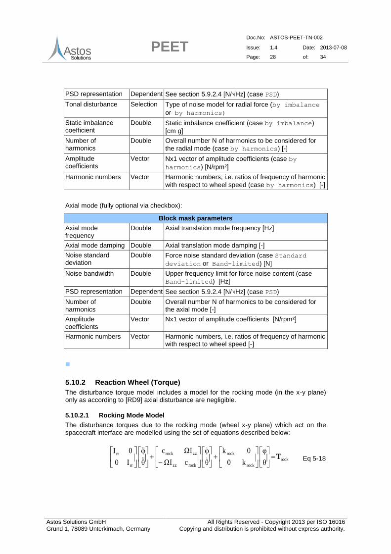
PSD representation Dependent See section 5.9.2.4 [N/√Hz] (case PSD)
Tonal disturbance Selection Type of noise model for radial force (by imbalance
or by harmonics)
Static imbalance coefficient
Double Static imbalance coefficient (case by imbalance)
[cm g]
Number of harmonics
Double Overall number N of harmonics to be considered for
the radial mode (case by harmonics) [-]
Amplitude coefficients
Vector Nx1 vector of amplitude coefficients (case by
harmonics) [N/rpm²]
Harmonic numbers Vector Harmonic numbers, i.e. ratios of frequency of harmonic
with respect to wheel speed (case by harmonics) [-]
Double Force noise standard deviation (case Standard
deviation or Band-limited) [N]
Noise bandwidth Double Upper frequency limit for force noise content (case
Band-limited) [Hz]
PSD representation Dependent See section 5.9.2.4 [N/√Hz] (case PSD)
Number of harmonics
Double Overall number N of harmonics to be considered for the axial mode [-]
Amplitude coefficients
Vector Nx1 vector of amplitude coefficients [N/rpm²]
Harmonic numbers Vector Harmonic numbers, i.e. ratios of frequency of harmonic with respect to wheel speed [-]
5.10.2 Reaction Wheel (Torque)
The disturbance torque model includes a model for the rocking mode (in the x-y plane) only as according to [RD9] axial disturbance are negligible.
5.10.2.1 Rocking Mode Model
The disturbance torques due to the rocking mode (wheel x-y plane) which act on the spacecraft interface are modelled using the set of equations described below:
rock
rock
rock
rockzz
zzrock
rr
rr
θ
φ
k0
0k
θ
φ
cIΩ
IΩc
θ
φ
I0
0IT
Eq 5-18
PEET Doc.No: ASTOS-PEET-TN-002
Issue: 1.4 Date: 2013-07-08
Page: 29 of: 34
Astos Solutions GmbH Grund 1, 78089 Unterkirnach, Germany
All Rights Reserved - Copyright 2013 per ISO 16016 Copying and distribution is prohibited without express authority.
AstosSolutions
rrrockrockrock Ifπξ4c Eq 5-19
2
rockrrrock )fπ2(Ik Eq 5-20
θ
φ
k0
0k
rock
rock
SC,rockT Eq 5-21
with:
rrI flywheel inertia perpendicular to spin axis
zzI flywheel inertia about spin axis
rockT (x,y) excitation torques for the rocking mode
rockξ damping of the rocking translation mode
rockf frequency of the rocking mode
SC,rockT resulting (x,y) disturbance torques at the spacecraft interface
5.10.2.2 Excitation Torque Model
According to [RD9] the overall excitation torque comprises (broadband) noise and tonal disturbances for the rocking mode and negligible disturbance torques around the z-axis
().
0
TT
TT
0
T
T
0noise,rocktonal,rock
noise,rocktonal,rock
rock
rock
rockTT Eq 5-22
Noise:
The noise contribution to the torque can be defined in different ways which correspond to selected options also available from the 'standard' PES block (section 5.9.2):
by definition of a standard deviation only (RV definition) by definition noise bandwidth upper frequency together with a standard deviation
which is converted to a PSD (random process definition) by direct definition of a PSD (random process definition)
Tonal disturbance:
The tonal torque contribution from the rocking mode is realized as one periodic 3D signal with amplitudes at frequencies of the corresponding harmonics. The amplitude Ak of the k-th harmonic (k=1...N, index for rocking mode omitted) and the corresponding frequency fk are obtained from:
2
kk ΩCA Eq 5-23
PEET Doc.No: ASTOS-PEET-TN-002
Issue: 1.4 Date: 2013-07-08
Page: 30 of: 34
Astos Solutions GmbH Grund 1, 78089 Unterkirnach, Germany
All Rights Reserved - Copyright 2013 per ISO 16016 Copying and distribution is prohibited without express authority.
AstosSolutions
Ωhπ2f kk Eq 5-24
where is the spin speed of the wheel, Ck is the amplitude coefficient of the k-th harmonic and hk the harmonic number (i.e. the ratio of frequency of k-th harmonic to spin frequency of the wheel.
Alternatively the rocking mode can also be defined by the dynamic imbalance coefficient Ud (i.e. considering only the first harmonic) resulting in an amplitude/frequency set:
2
d1 ΩUA Eq 5-25
Ωπ2f1 Eq 5-26
The wheel speed is assumed to be constant within a single observation period. This can be understood as a "linearization" around a certain working point during the observation.
In addition it has to be noted that there is no distinction between the radial axes
amplitudes ( and ) although the time-based model in [RD9] accounts for the 90° phase shift between the axes for each harmonic. This is however no restriction of the model as from a performance point of view only the overall magnitude or temporal mean is of interest when applying the statistical interpretation.
Furthermore it has to be noted that the arbitrary phase angle between different harmonics cannot be directly accounted for as in the time-domain model from [RD9]. As a full correlation between the different harmonics and axes) might be too pessimistic, an uncorrelated set is realized in the PEET model.
5.10.2.3 Block Parameters
The following tables summarize the parameters to be defined by the user.
Wheel properties:
Block mask parameters
Inertia about spin axis
Double Wheel inertia about spin axis [kg m²]
Inertia perpendicular to spin axis
Double Wheel inertia perpendicular to spin axis [kg m²]
Wheel speed Double Rotational speed of the reaction wheel [rpm]
Rocking mode:
Block mask parameters
Rocking mode frequency
Double Rocking mode frequency [Hz]
Rocking mode damping
Double Rocking mode damping [-]
Broadband noise Selection Type of noise model for torque (Standard
deviation, Band-limited or PSD)
Noise standard Double Torque noise standard deviation (case Standard
PEET Doc.No: ASTOS-PEET-TN-002
Issue: 1.4 Date: 2013-07-08
Page: 31 of: 34
Astos Solutions GmbH Grund 1, 78089 Unterkirnach, Germany
All Rights Reserved - Copyright 2013 per ISO 16016 Copying and distribution is prohibited without express authority.
AstosSolutions
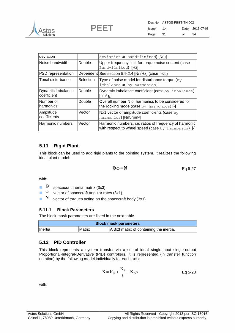
deviation deviation or Band-limited) [Nm]
Noise bandwidth Double Upper frequency limit for torque noise content (case
Band-limited) [Hz]
PSD representation Dependent See section 5.9.2.4 [N/√Hz] (case PSD)
Tonal disturbance Selection Type of noise model for disturbance torque (by
imbalance or by harmonics)
Dynamic imbalance coefficient
Double Dynamic imbalance coefficient (case by imbalance)
[cm² g]
Number of harmonics
Double Overall number N of harmonics to be considered for
the rocking mode (case by harmonics) [-]
Amplitude coefficients
Vector Nx1 vector of amplitude coefficients (case by
harmonics) [Nm/rpm²]
Harmonic numbers Vector Harmonic numbers, i.e. ratios of frequency of harmonic
with respect to wheel speed (case by harmonics) [-]
5.11 Rigid Plant
This block can be used to add rigid plants to the pointing system. It realizes the following ideal plant model:
NωΘ Eq 5-27
with:
Θ spacecraft inertia matrix (3x3)
ω vector of spacecraft angular rates (3x1)
N vector of torques acting on the spacecraft body (3x1)
5.11.1 Block Parameters
The block mask parameters are listed in the next table.
Block mask parameters
Inertia Matrix A 3x3 matrix of containing the inertia.
5.12 PID Controller
This block represents a system transfer via a set of ideal single-input single-output Proportional-Integral-Derivative (PID) controllers. It is represented (in transfer function notation) by the following model individually for each axis:
sKs
KKK D
IP Eq 5-28
with:
PEET Doc.No: ASTOS-PEET-TN-002
Issue: 1.4 Date: 2013-07-08
Page: 32 of: 34
Astos Solutions GmbH Grund 1, 78089 Unterkirnach, Germany
All Rights Reserved - Copyright 2013 per ISO 16016 Copying and distribution is prohibited without express authority.
AstosSolutions
K total controller transfer function
PK proportional gain of the controller
IK integral gain of the controller
DK differential gain of the controller
s 'Laplace variable'
5.12.1 Block Parameters
The block mask parameters are listed in the next table.
Block mask parameters
P-Gains Vector A vector containing the proportional gains for each axis.
I-Gains Vector A vector containing the integral gains for each axis.
D-Gains Vector A vector containing the differential gains for each axis.
Note that per definition of this block only a single 3D input signal can be fed to the PID controller. However, more complex inputs (e.g. feeding an attitude signal to the proportional part and a rate signal to the differential one) can be realized by proper modification of the desired closed-loop structure. An example for such realization is given in section 6.2.8.3 of [RD2].
5.13 Static System Block
The static system block is used to model all kind of static systems. The static system block is using a 3x3 static gain matrix as the system model. The elements of the system transfer matrix are double values.
5.13.1 Block Parameters
The block mask parameters for the static system block are listed below.
Block mask parameters
System matrix Matrix A 3x3 matrix of double values, describing the system transfer.
5.14 Summation Block
The summation block is used to sum up several error signals to one single signal. It offers the user a single block mask parameter. This parameter defines the number of input ports of the summation block and is listed below.
Block mask parameters
Number of input ports Selection The number of block input ports. The number of input ports is in the range from 1 to 99.
PEET Doc.No: ASTOS-PEET-TN-002
Issue: 1.4 Date: 2013-07-08
Page: 33 of: 34
Astos Solutions GmbH Grund 1, 78089 Unterkirnach, Germany
All Rights Reserved - Copyright 2013 per ISO 16016 Copying and distribution is prohibited without express authority.
AstosSolutions
5.15 Star Tracker Noise Block
This special error source block implements a parametric model for the pixel and field of view noise of a typical star tracker (temporal noise is not included and has to be defined in a separate pointing error source block, e.g. as 'standard' random process of type desired by the user). The underlying model is briefly described below, starting with the spectrum of the field of view noise:
FOVFOV
FOV
FOV n
2
Ts1
TPSD
Eq 5-29
The correlation time FOVT is assumed to be proportional to the inverse of the velocity
starv (pixels/sec) with which the star image moves on the sensor pixel matrix:
starsstar
FOVNv
1024T Eq 5-30
The star velocity itself can be linked to the average spacecraft angular velocity SCω :
αcosβsinFOV
1024ωvstar Eq 5-31
where FOV is the sensor field, is the angle between the sensor boresight and the
spacecraft rotation axis and is the angle between the star image direction of motion on the detector matrix and the reference axis.
The PSD of the field of view noise can be modelled using a 2nd-order filter as:
pixel2
00
2
pixel
2
0
pixel nωsξω2s
TωPSD
Eq 5-32
where the characteristic frequency 0ω is given by:
pixel
0T
ξ4ω Eq 5-33
The correlation time pixelT is again assumed to be proportional to the inverse of the
velocity starv :
star
pixels
pixelv
NT Eq 5-34
PEET Doc.No: ASTOS-PEET-TN-002
Issue: 1.4 Date: 2013-07-08
Page: 34 of: 34
Astos Solutions GmbH Grund 1, 78089 Unterkirnach, Germany
All Rights Reserved - Copyright 2013 per ISO 16016 Copying and distribution is prohibited without express authority.
AstosSolutions
where pixelsN is the size of the centroiding window.
5.15.1 Block Parameters
The block mask parameters for the star tracker noise are listed in the next table, subdivided into general parameters, field of view noise parameters and pixel noise parameters.
General parameters:
Block mask parameters
Detector size Double Number of detector pixels.
Sensor field of view Double Field of view of the sensor camera head.
Spacecraft angular velocity
Double Average spacecraft angular velocity.
Average number of tracked stars
Double Average number of stars tracked by the sensor.
Alpha* Double The angle between the star image direction of motion on the detector matrix and the reference axis.
Beta* Double The angle between the sensor boresight and the spacecraft rotation axis.
*Note: For a worst-case set Alpha to 0 and Beta to /2.
Field of view noise parameters:
Block mask parameters
Noise level Double The low frequency noise level for all axes
Pixel noise parameters:
Block mask parameters
Size of centroiding window
Double The size of the centroiding window in pixels.
Noise level (boresight)
Double The low frequency noise level for the sensor boresight axis.
Noise level (cross-axes)
Double The low frequency noise level for the cross boresight axes.
2nd-order filter filter damping coefficient
Double The damping coefficient used for the pixel noise transfer function.


![Pointing Error Engineering Tool - European Space Agencypeet.estec.esa.int/files/ASTOS-PEET-TN-001_Iss1.3...[AD3] ECSS-E-HB-60-10A; Space Engineering, Control Performance Guidelines](https://static.documents.pub/doc/80x56/612e87091ecc51586942dec0/pointing-error-engineering-tool-european-space-ad3-ecss-e-hb-60-10a-space.jpg)


