57
PoKeys protocol specification copyright PoLabs 2011 All rights reserved

PoKeys protocol specification
copyright PoLabs 2011
All rights reserved
Brief protocol description
USB PoKeys55 are USB HID devices that use OS's integrated drivers to communicate with software. No additional
drivers are neccessary to communicate with devices.
PoKeys55 use these Vendor and Product IDs:
idVendor: 0x1DC3
idProduct: 0x1001
The device encapsulates three interfaces, first (index 0) being standard USB HID keyboard, second (index 1)
being PoKeys communication interface and the third (index 2) standard USB HID Joystick.
Configuration is set or read using the second interface. The PoKeys device is found by searching among
connected HID devices and looking their PathNames. If the PathName contains
hid#vid_1dc3&pid_1001&mi_01, this is the correct interface to PoKeys device. If more than one PoKeys device
is connected to the same host, differentiation at this level is impossible, so user ID byte must be read from the
PoKeys device.
In PoKeys communication DLL, request are handled this way:
1. send report with a unique request ID (simply ever-increasing value)
2. read report
3. check Requst ID, if it does not match the one in (1), sleep for 1 ms and then go to (2) (try this 5 times,
then terminate)
4. check packet checksum, if it does not match go to (1) (try this 2 times, then terminate)
Communication
To ensure a highest possible compatibility with USB PoKeys devices, PoKeys56E uses Extended packet mode as
described below. Packets are transfered with TCP protocol.
Network edition PoKeys56E uses a combination of UDP and TCP packets to communicate with the host. Both use a port number
20055.
Device discovery
PoKeys56E modules are discovered via broadcast UDP packets. A host sends out a UDP packet with a
broadcasting address. All PoKeys56E devices respond with another UDP packet that contains the device's
identification (User ID, serial number, version) and it's IP address.
Packet data is formated the following way:
Host -> device: empty packet (ignored)
Device -> host
- byte 1: User ID number
- bytes 2,3: Serial number
- bytes 4,5: Version
- bytes 6,7,8,9: IP address
Communication
All further communication with the device is acomplished with TCP connection on port 20055. Packet structure
is 64-bytes long and is described below as Extended packet mode.
Security
PoKeys56E supports additional security option that requires the user to enter the password before the access
to the device is granted. The password can contain any character and can be up to 32 characters long.
Connection timeout
After 3 seconds of inactivity, PoKeys56E terminates the connection with the host (except for Modbus, where
connection timeout is settable by user).
Packet formatting
Incoming and outgoing packets are 64 bytes long. Basic packets use only first 8 bytes. Extended packets use the
whole packet.
Host>Device
- byte 1: control 0xBB - byte 2: operation - byte 3-6: operation parameters - byte 7: request ID - byte 8: control byte (sum after mod 0x100)
Device>Host
- byte 1: control 0xAA - byte 2: operation - byte 3-6: operation parameters - byte 7: request ID - byte 8: control byte (sum after mod 0x100)
Extended packet mode (supported since version 1.8)
Packet size is increased to 64 bytes. First 8 bytes remain the same, additional 56 bytes are used for extended
mode. Additional checksum value is added as the last (64.) byte. It is the checksum for the whole 63 bytes of
packet (except for command 0x7A that sends 56 bytes of data and checksum in the header).
Supported commands:
Brief protocol description ....................................................................................................................................2
USB ..................................................................................................................................................................2
Communication ...........................................................................................................................................2
Network edition ..............................................................................................................................................2
Device discovery .........................................................................................................................................2
Communication ...........................................................................................................................................3
Security .......................................................................................................................................................3
Packet formatting ................................................................................................................................................3
Supported commands: ........................................................................................................................................4
Standard mode operations:.............................................................................................................................7
Extended mode operations: ............................................................................................................................8
General ..........................................................................................................................................................10
Read serial .................................................................................................................................................10
Set user ID .................................................................................................................................................10
Read user ID ..............................................................................................................................................10
Read build date .........................................................................................................................................11
Configuration saving .................................................................................................................................11
Configuration saving and lock ...................................................................................................................11
Configuration reset ...................................................................................................................................12
Get system load status ..............................................................................................................................12
Get tick counter ........................................................................................................................................12
General pin settings.......................................................................................................................................13
Set input/output settings .........................................................................................................................13
Read input/output settings .......................................................................................................................13
Input/output settings - extended mode ...................................................................................................14
Key association setting (for pins which are set to 1, 2 or 32) ...................................................................14
Reading of key associations ......................................................................................................................15
Typematic delay setup ..............................................................................................................................15
Key repeat rate setup................................................................................................................................16
Key mappings ............................................................................................................................................16
Key codes ..................................................................................................................................................17
Key modifiers ............................................................................................................................................17
Triggered input key mappings ..................................................................................................................17
Get/Set Connection signal pin status ........................................................................................................18

Encoder settings ............................................................................................................................................20
Encoder settings........................................................................................................................................20
Encoder key mapping for direction A .......................................................................................................20
Encoder key mapping for direction B........................................................................................................20
Read encoder settings...............................................................................................................................21
Read encoder key mapping for direction A ..............................................................................................21
Read encoder key mapping for direction B...............................................................................................21
Read encoder RAW value..........................................................................................................................22
Reset encoder RAW value .........................................................................................................................22
Encoder option..........................................................................................................................................22
Encoder channel A and B pin ....................................................................................................................23
Encoder channel A key code and modifier ...............................................................................................23
Encoder channel B key code and modifier................................................................................................24
Get encoder long RAW values ..................................................................................................................24
Enable/disable fast encoders on pins 1-2, 3-4 / 5-6 and 15-16..............................................................25
Enable/disable ultra fast encoder .............................................................................................................26
Digital counters .............................................................................................................................................27
Get digital counters values .......................................................................................................................27
Reset digital counters values ....................................................................................................................27
I/O operations ...............................................................................................................................................29
Reading of inputs ......................................................................................................................................29
Block inputs reading..................................................................................................................................29
Block inputs reading - part 2 .....................................................................................................................29
Analog inputs reading: ..............................................................................................................................30
Analog inputs block reading - 4x 8bit ........................................................................................................30
Analog inputs block reading - 3x 10bit ......................................................................................................30
Analog inputs reading – all analog inputs in one command .....................................................................31
Get analog RC filter value .........................................................................................................................31
Set analog RC filter value ..........................................................................................................................31
Outputs setting .........................................................................................................................................31
Block outputs writing ................................................................................................................................32
Analog ouputs settings..............................................................................................................................32
Get device status (extended mode - IO, analog, encoders) ......................................................................32
Joystick settings .............................................................................................................................................34
Read joystick configuration.......................................................................................................................34
Set joystick configuration..........................................................................................................................34
Get joystick up Event buttons configuration ............................................................................................34
Set joystick up Event buttons configuration .............................................................................................35
Set/Get joystick analog to digital key mapping options............................................................................35
Macros ...........................................................................................................................................................38
Create macro ............................................................................................................................................38
Modify macro ............................................................................................................................................38
Delete macro.............................................................................................................................................38
Save macros to flash .................................................................................................................................39
Rename macro ..........................................................................................................................................39
Transfer macro ..........................................................................................................................................40
Get macro length ......................................................................................................................................40
Get macro name .......................................................................................................................................40
Get macro keys .........................................................................................................................................41
Get free space ...........................................................................................................................................41
Get active macros .....................................................................................................................................42
Set/Get macro name and length...............................................................................................................42
Set/Get macro keys ...................................................................................................................................42
Matrix keyboard ............................................................................................................................................44
Get/Set matrix keyboard configuration ....................................................................................................44
PWM channels...............................................................................................................................................46
Get/set PWM configuration ......................................................................................................................46
LCD displays ...................................................................................................................................................47
Set LCD configuration................................................................................................................................47
LCD operation ...........................................................................................................................................47
Matrix LED display operations .......................................................................................................................49
Get/set Matrix LED display configuration .................................................................................................49
Update matrix LED display ........................................................................................................................50
Auxilary bus ...................................................................................................... Error! Bookmark not defined.
Set auxilary bus settings............................................................................................................................51
Network settings ...........................................................................................................................................55
Get/set network configuration .................................................................................................................55
Get security setting status ........................................................................................................................55
Autorise user .............................................................................................................................................56
Set user password .....................................................................................................................................56
Modbus settings ............................................................................................................................................57
Get/set modbus settings...........................................................................................................................57
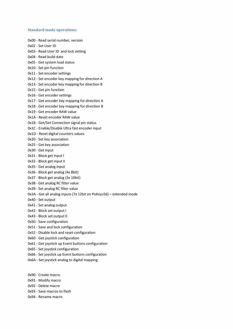
Standard mode operations:
0x00 - Read serial number, version
0x02 - Set User ID
0x03 - Read User ID and lock setting
0x04 - Read build date
0x05 - Get system load status
0x10 - Set pin function
0x11 - Set encoder settings
0x12 - Set encoder key mapping for direction A
0x13 - Set encoder key mapping for direction B
0x15 - Get pin function
0x16 - Get encoder settings
0x17 - Get encoder key mapping for direction A
0x18 - Get encoder key mapping for direction B
0x19 - Get encoder RAW value
0x1A - Reset encoder RAW value
0x1B - Get/Set Connection signal pin status
0x1C - Enable/Disable Ultra fast encoder input
0x1D - Reset digital counters values
0x20 - Set key association
0x25 - Get key association
0x30 - Get input
0x31 - Block get input I
0x32 - Block get input II
0x35 - Get analog input
0x36 - Block get analog (4x 8bit)
0x37 - Block get analog (3x 10bit)
0x38 - Get analog RC filter value
0x39 - Set analog RC filter value
0x3A - Get all analog inputs (7x 12bit on PoKeys56) – extended mode
0x40 - Set output
0x41 - Set analog output
0x42 - Block set output I
0x43 - Block set output II
0x50 - Save configuration
0x51 - Save and lock configuration
0x52 - Disable lock and reset configuration
0x60 - Get joystick configuration
0x61 - Get joystick up Event buttons configuration
0x65 - Set joystick configuration
0x66 - Set joystick up Event buttons configuration
0x6A - Set joystick analog to digital mapping
0x90 - Create macro
0x91 - Modify macro
0x92 - Delete macro
0x93 - Save macros to flash
0x94 - Rename macro
0x95 - Transfer macro
0x96 - Get macro length
0x97 - Get macro name
0x98 - Get macro keys
0x99 - Get free space
0x9A - Get active macros
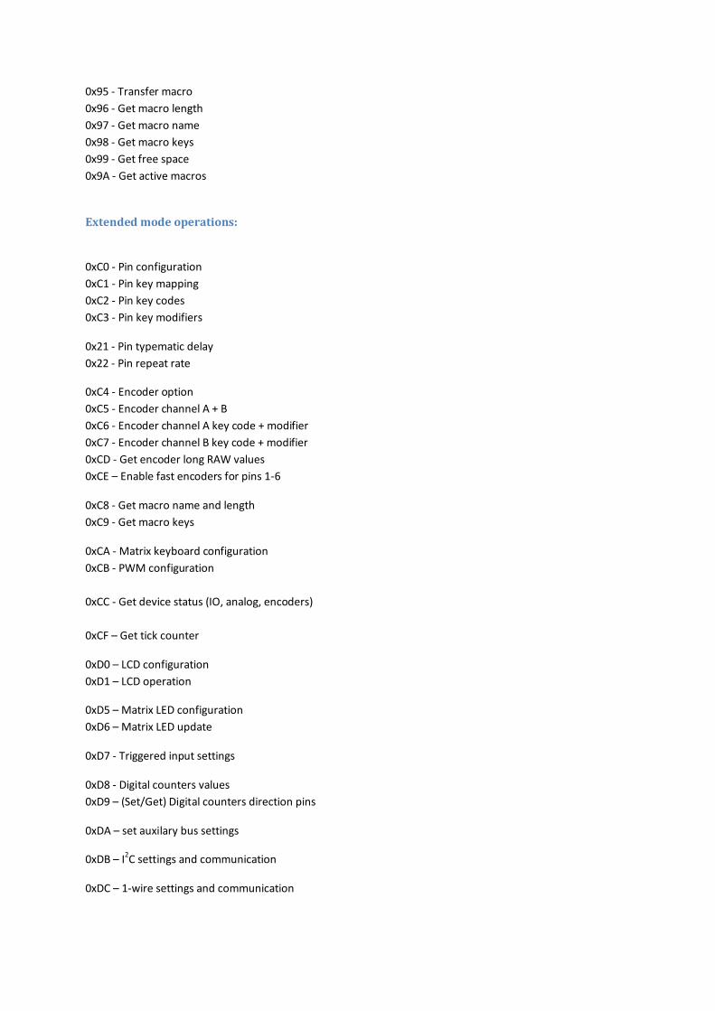
Extended mode operations:
0xC0 - Pin configuration
0xC1 - Pin key mapping
0xC2 - Pin key codes
0xC3 - Pin key modifiers
0x21 - Pin typematic delay
0x22 - Pin repeat rate
0xC4 - Encoder option
0xC5 - Encoder channel A + B
0xC6 - Encoder channel A key code + modifier
0xC7 - Encoder channel B key code + modifier
0xCD - Get encoder long RAW values
0xCE – Enable fast encoders for pins 1-6
0xC8 - Get macro name and length
0xC9 - Get macro keys
0xCA - Matrix keyboard configuration
0xCB - PWM configuration
0xCC - Get device status (IO, analog, encoders)
0xCF – Get tick counter
0xD0 – LCD configuration
0xD1 – LCD operation
0xD5 – Matrix LED configuration
0xD6 – Matrix LED update
0xD7 - Triggered input settings
0xD8 - Digital counters values
0xD9 – (Set/Get) Digital counters direction pins
0xDA – set auxilary bus settings
0xDB – I2C settings and communication
0xDC – 1-wire settings and communication

0xE0 – Get/set network settings
0xE1 – Get security setting status (and password hash seed)
0xE2 – Authorise user
0xE3 – Set user password
0xE4 – Get/Set Modbus settings
Bootloader operations
0xF0 – clear application memory
0xF1 – block transfer options
0xF2 – transfer block part
0xF3 – start application
0xF5 – calculate and save CRC
0xF6 – clear user settings

General
Read serial
- byte 2: 0x00 - byte 3-6: 0 - byte 7: request ID
Returned packet:
- byte 2: 0x00
- byte 3: serial MSB
- byte 4: serial LSB
- byte 5: software version (v(1+[4-7]).([0-3]))
- byte 6: revision number
- byte 7: request ID
Set user ID
- byte 2: 0x02
- byte 3: ID
- byte 4-6: 0
- byte 7: request ID
Returned packet:
- byte 2: 0x02
- byte 3: confirmed ID
- byte 4-6: 0
- byte 7: request ID
Read user ID
- byte 2: 0x03
- byte 3-6: 0
- byte 7: request ID
Returned packet:
- byte 2: 0x03
- byte 3: userID
- byte 4: device lock status (if 1, device configuration is locked)
- byte 5-6: 0
- byte 7: request ID
Read/set device name
- byte 2: 0x06
- byte 3: 1 for writing, 0 for reading
- byte 4-6: 0
- byte 7: request ID
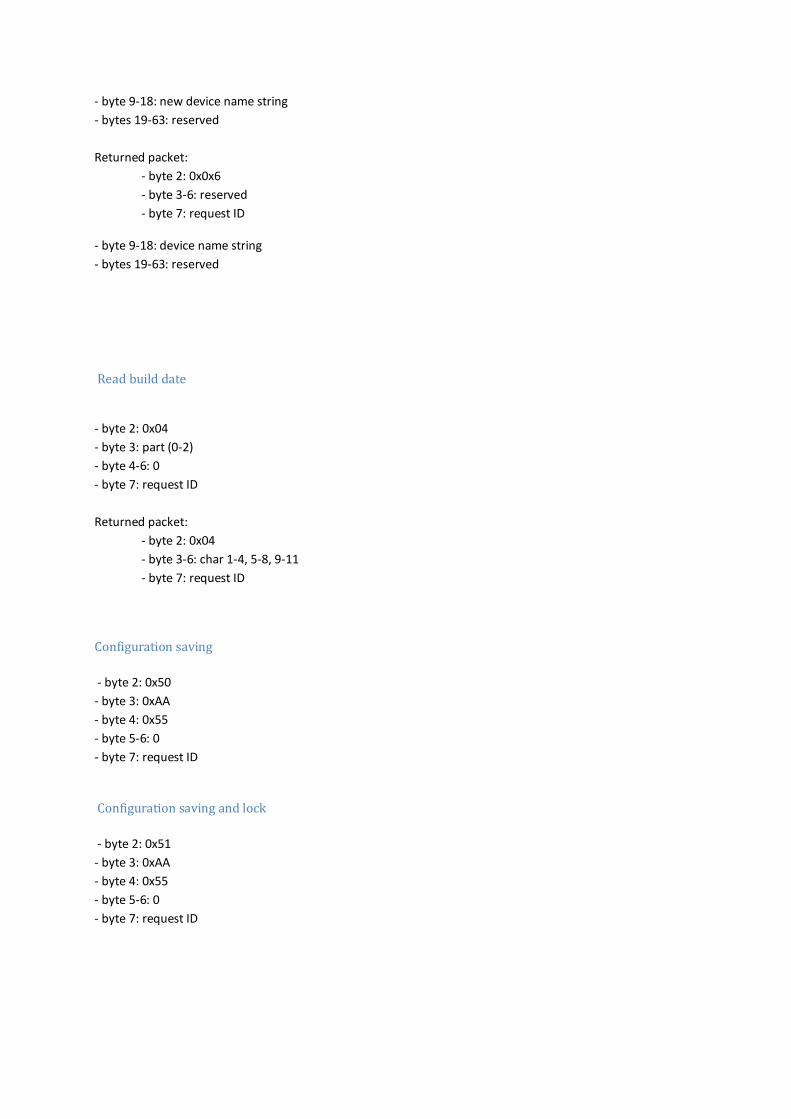
- byte 9-18: new device name string
- bytes 19-63: reserved
Returned packet:
- byte 2: 0x0x6
- byte 3-6: reserved
- byte 7: request ID
- byte 9-18: device name string
- bytes 19-63: reserved
Read build date
- byte 2: 0x04
- byte 3: part (0-2)
- byte 4-6: 0
- byte 7: request ID
Returned packet:
- byte 2: 0x04
- byte 3-6: char 1-4, 5-8, 9-11
- byte 7: request ID
Configuration saving
- byte 2: 0x50
- byte 3: 0xAA
- byte 4: 0x55
- byte 5-6: 0
- byte 7: request ID
Configuration saving and lock
- byte 2: 0x51
- byte 3: 0xAA
- byte 4: 0x55
- byte 5-6: 0
- byte 7: request ID
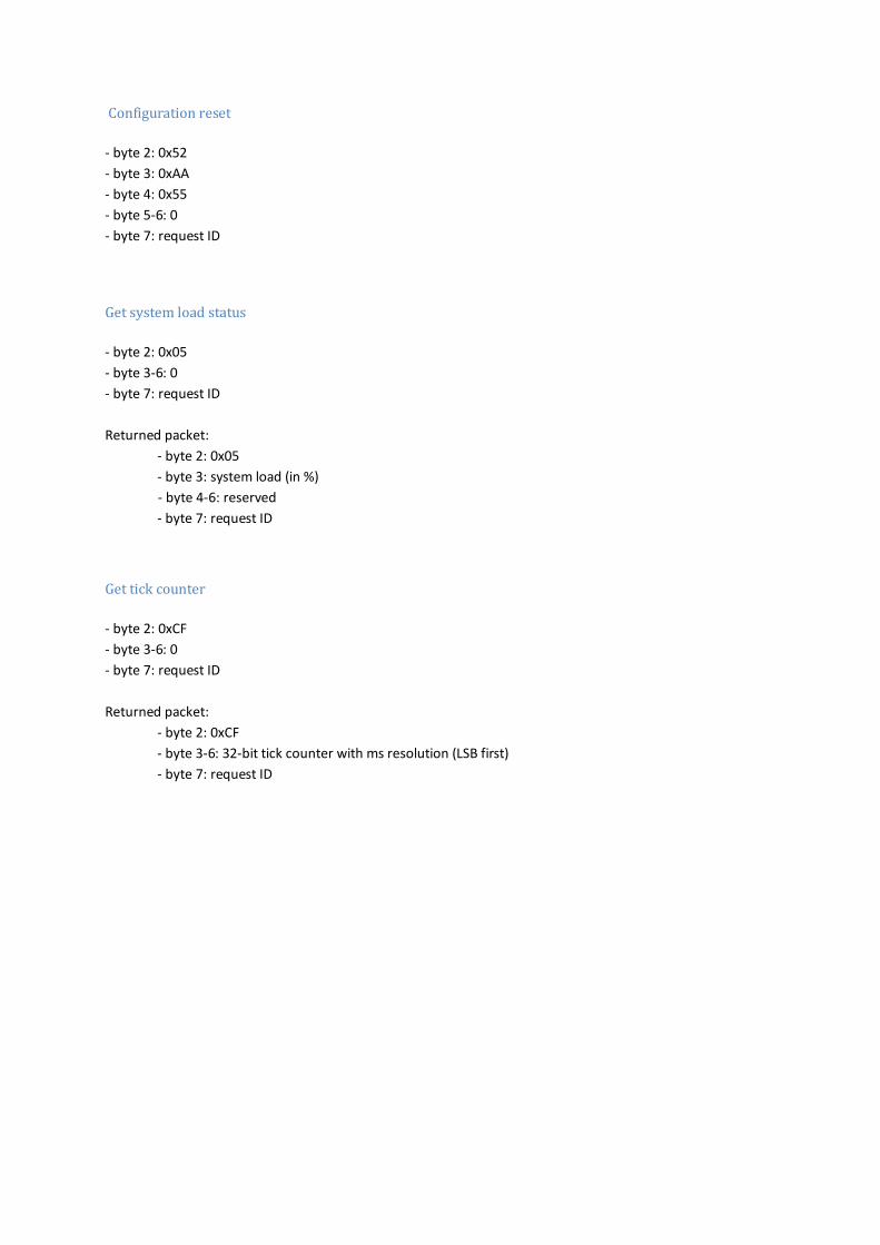
Configuration reset
- byte 2: 0x52
- byte 3: 0xAA
- byte 4: 0x55
- byte 5-6: 0
- byte 7: request ID
Get system load status
- byte 2: 0x05
- byte 3-6: 0
- byte 7: request ID
Returned packet:
- byte 2: 0x05
- byte 3: system load (in %)
- byte 4-6: reserved
- byte 7: request ID
Get tick counter
- byte 2: 0xCF
- byte 3-6: 0
- byte 7: request ID
Returned packet:
- byte 2: 0xCF
- byte 3-6: 32-bit tick counter with ms resolution (LSB first)
- byte 7: request ID
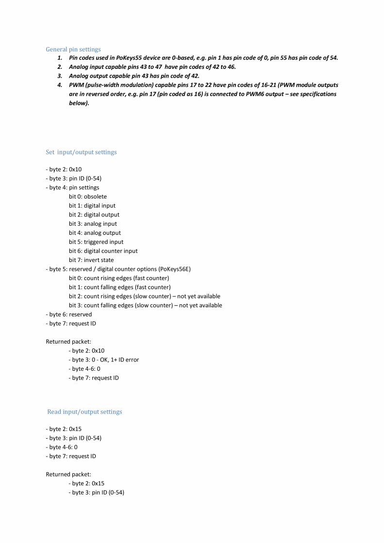
General pin settings
1. Pin codes used in PoKeys55 device are 0-based, e.g. pin 1 has pin code of 0, pin 55 has pin code of 54.
2. Analog input capable pins 43 to 47 have pin codes of 42 to 46.
3. Analog output capable pin 43 has pin code of 42.
4. PWM (pulse-width modulation) capable pins 17 to 22 have pin codes of 16-21 (PWM module outputs
are in reversed order, e.g. pin 17 (pin coded as 16) is connected to PWM6 output – see specifications
below).
Set input/output settings
- byte 2: 0x10
- byte 3: pin ID (0-54)
- byte 4: pin settings
bit 0: obsolete
bit 1: digital input
bit 2: digital output
bit 3: analog input
bit 4: analog output
bit 5: triggered input
bit 6: digital counter input
bit 7: invert state
- byte 5: reserved / digital counter options (PoKeys56E)
bit 0: count rising edges (fast counter)
bit 1: count falling edges (fast counter)
bit 2: count rising edges (slow counter) – not yet available
bit 3: count falling edges (slow counter) – not yet available
- byte 6: reserved
- byte 7: request ID
Returned packet:
- byte 2: 0x10
- byte 3: 0 - OK, 1+ ID error
- byte 4-6: 0
- byte 7: request ID
Read input/output settings
- byte 2: 0x15
- byte 3: pin ID (0-54)
- byte 4-6: 0
- byte 7: request ID
Returned packet:
- byte 2: 0x15
- byte 3: pin ID (0-54)
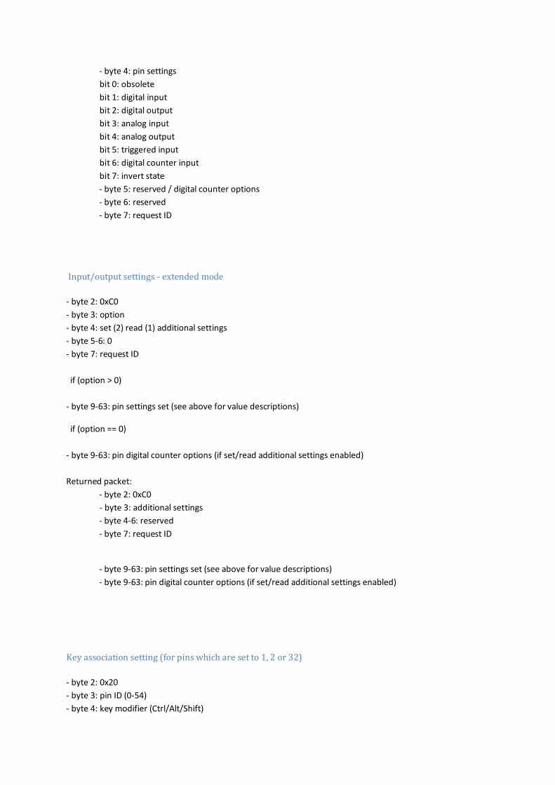
- byte 4: pin settings
bit 0: obsolete
bit 1: digital input
bit 2: digital output
bit 3: analog input
bit 4: analog output
bit 5: triggered input
bit 6: digital counter input
bit 7: invert state
- byte 5: reserved / digital counter options
- byte 6: reserved
- byte 7: request ID
Input/output settings - extended mode
- byte 2: 0xC0
- byte 3: option
- byte 4: set (2) read (1) additional settings
- byte 5-6: 0
- byte 7: request ID
if (option > 0)
- byte 9-63: pin settings set (see above for value descriptions)
if (option == 0)
- byte 9-63: pin digital counter options (if set/read additional settings enabled)
Returned packet:
- byte 2: 0xC0
- byte 3: additional settings
- byte 4-6: reserved
- byte 7: request ID
- byte 9-63: pin settings set (see above for value descriptions)
- byte 9-63: pin digital counter options (if set/read additional settings enabled)
Key association setting (for pins which are set to 1, 2 or 32)
- byte 2: 0x20
- byte 3: pin ID (0-54)
- byte 4: key modifier (Ctrl/Alt/Shift)
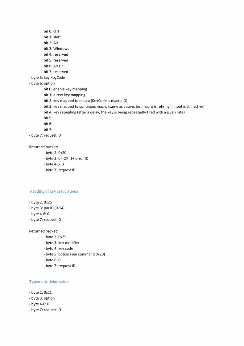
bit 0: ctrl
bit 1: shift
bit 2: Alt
bit 3: Windows
bit 4: reserved
bit 5: reserved
bit 6: Alt Gr
bit 7: reserved
- byte 5: key KeyCode
- byte 6: option
bit 0: enable key mapping
bit 1: direct key mapping
bit 2: key mapped to macro (KeyCode is macro ID)
bit 3: key mapped to continous macro (same as above, but macro is refiring if input is still active)
bit 4: key repeating (after a delay, the key is being repeatedly fired with a given rate)
bit 5:
bit 6:
bit 7:
- byte 7: request ID
Returned packet:
- byte 2: 0x20
- byte 3: 0 - OK, 1+ error ID
- byte 4-6: 0
- byte 7: request ID
Reading of key associations
- byte 2: 0x25
- byte 3: pin ID (0-54)
- byte 4-6: 0
- byte 7: request ID
Returned packet:
- byte 2: 0x25
- byte 3: key modifier
- byte 4: key code
- byte 5: option (see command 0x20)
- byte 6: 0
- byte 7: request ID
Typematic delay setup
- byte 2: 0x21
- byte 3: option
- byte 4-6: 0
- byte 7: request ID
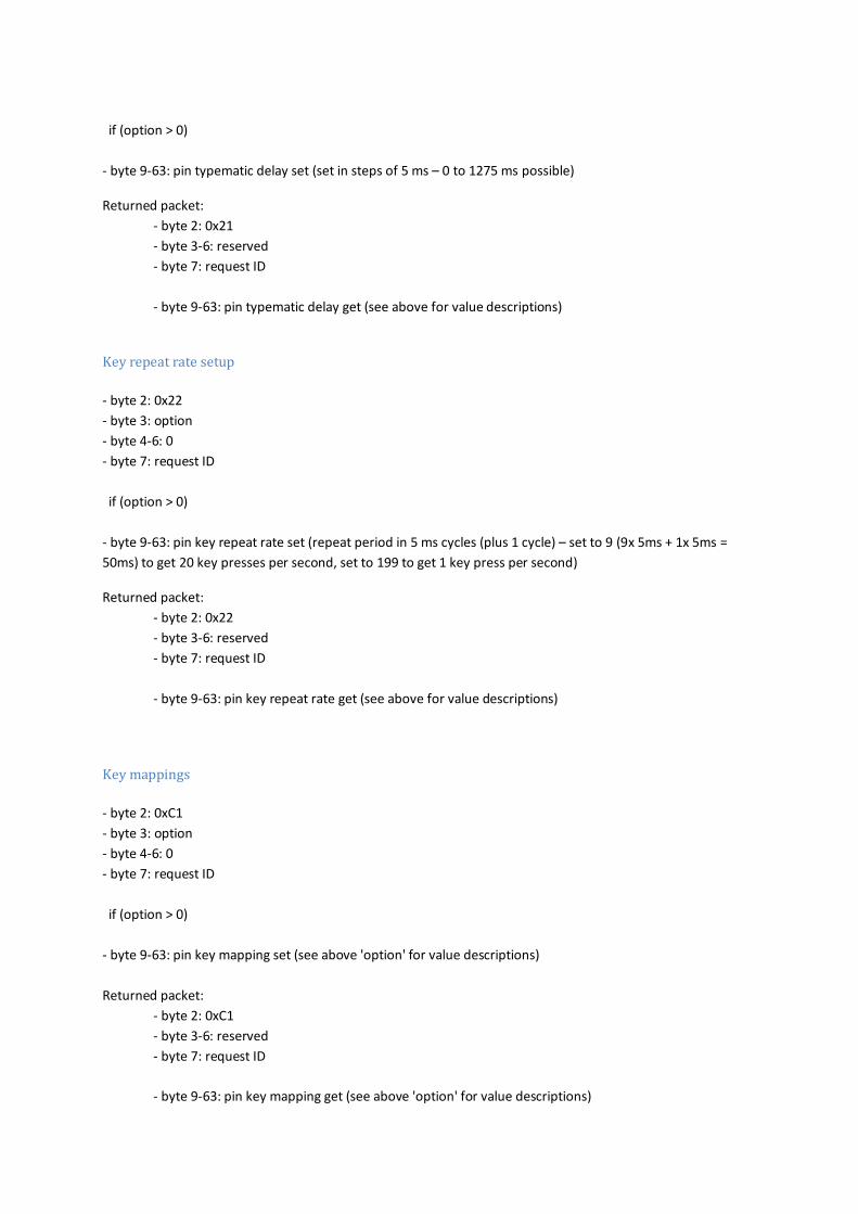
if (option > 0)
- byte 9-63: pin typematic delay set (set in steps of 5 ms – 0 to 1275 ms possible)
Returned packet:
- byte 2: 0x21
- byte 3-6: reserved
- byte 7: request ID
- byte 9-63: pin typematic delay get (see above for value descriptions)
Key repeat rate setup
- byte 2: 0x22
- byte 3: option
- byte 4-6: 0
- byte 7: request ID
if (option > 0)
- byte 9-63: pin key repeat rate set (repeat period in 5 ms cycles (plus 1 cycle) – set to 9 (9x 5ms + 1x 5ms =
50ms) to get 20 key presses per second, set to 199 to get 1 key press per second)
Returned packet:
- byte 2: 0x22
- byte 3-6: reserved
- byte 7: request ID
- byte 9-63: pin key repeat rate get (see above for value descriptions)
Key mappings
- byte 2: 0xC1
- byte 3: option
- byte 4-6: 0
- byte 7: request ID
if (option > 0)
- byte 9-63: pin key mapping set (see above 'option' for value descriptions)
Returned packet:
- byte 2: 0xC1
- byte 3-6: reserved
- byte 7: request ID
- byte 9-63: pin key mapping get (see above 'option' for value descriptions)
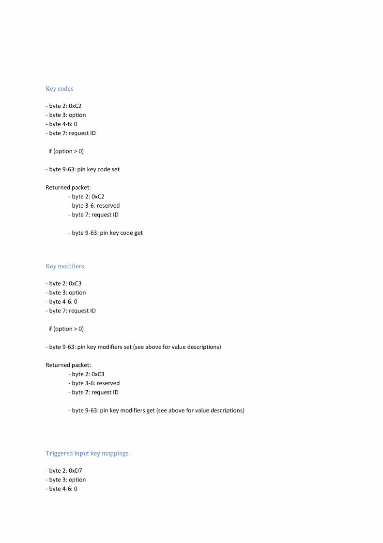
Key codes
- byte 2: 0xC2
- byte 3: option
- byte 4-6: 0
- byte 7: request ID
if (option > 0)
- byte 9-63: pin key code set
Returned packet:
- byte 2: 0xC2
- byte 3-6: reserved
- byte 7: request ID
- byte 9-63: pin key code get
Key modifiers
- byte 2: 0xC3
- byte 3: option
- byte 4-6: 0
- byte 7: request ID
if (option > 0)
- byte 9-63: pin key modifiers set (see above for value descriptions)
Returned packet:
- byte 2: 0xC3
- byte 3-6: reserved
- byte 7: request ID
- byte 9-63: pin key modifiers get (see above for value descriptions)
Triggered input key mappings
- byte 2: 0xD7
- byte 3: option
- byte 4-6: 0
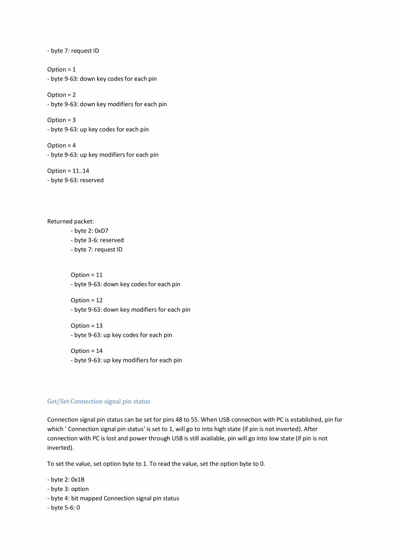
- byte 7: request ID
Option = 1
- byte 9-63: down key codes for each pin
Option = 2
- byte 9-63: down key modifiers for each pin
Option = 3
- byte 9-63: up key codes for each pin
Option = 4
- byte 9-63: up key modifiers for each pin
Option = 11..14
- byte 9-63: reserved
Returned packet:
- byte 2: 0xD7
- byte 3-6: reserved
- byte 7: request ID
Option = 11
- byte 9-63: down key codes for each pin
Option = 12
- byte 9-63: down key modifiers for each pin
Option = 13
- byte 9-63: up key codes for each pin
Option = 14
- byte 9-63: up key modifiers for each pin
Get/Set Connection signal pin status
Connection signal pin status can be set for pins 48 to 55. When USB connection with PC is established, pin for
which ' Connection signal pin status' is set to 1, will go to into high state (if pin is not inverted). After
connection with PC is lost and power through USB is still available, pin will go into low state (if pin is not
inverted).
To set the value, set option byte to 1. To read the value, set the option byte to 0.
- byte 2: 0x1B
- byte 3: option
- byte 4: bit mapped Connection signal pin status
- byte 5-6: 0

- byte 7: request ID
Returned packet:
- byte 2: 0x1B
- byte 3: reserved
- byte 4: bit mapped Connection signal pin status
- byte 5-6: reserved
- byte 7: request ID
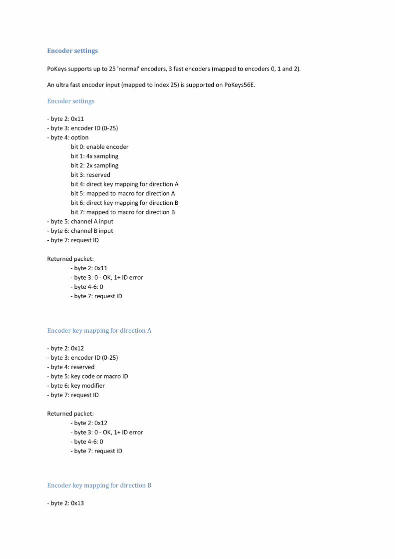
Encoder settings
PoKeys supports up to 25 'normal' encoders, 3 fast encoders (mapped to encoders 0, 1 and 2).
An ultra fast encoder input (mapped to index 25) is supported on PoKeys56E.
Encoder settings
- byte 2: 0x11
- byte 3: encoder ID (0-25)
- byte 4: option
bit 0: enable encoder
bit 1: 4x sampling
bit 2: 2x sampling
bit 3: reserved
bit 4: direct key mapping for direction A
bit 5: mapped to macro for direction A
bit 6: direct key mapping for direction B
bit 7: mapped to macro for direction B
- byte 5: channel A input
- byte 6: channel B input
- byte 7: request ID
Returned packet:
- byte 2: 0x11
- byte 3: 0 - OK, 1+ ID error
- byte 4-6: 0
- byte 7: request ID
Encoder key mapping for direction A
- byte 2: 0x12
- byte 3: encoder ID (0-25)
- byte 4: reserved
- byte 5: key code or macro ID
- byte 6: key modifier
- byte 7: request ID
Returned packet:
- byte 2: 0x12
- byte 3: 0 - OK, 1+ ID error
- byte 4-6: 0
- byte 7: request ID
Encoder key mapping for direction B
- byte 2: 0x13
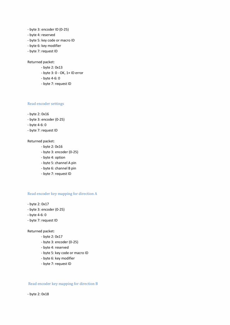
- byte 3: encoder ID (0-25)
- byte 4: reserved
- byte 5: key code or macro ID
- byte 6: key modifier
- byte 7: request ID
Returned packet:
- byte 2: 0x13
- byte 3: 0 - OK, 1+ ID error
- byte 4-6: 0
- byte 7: request ID
Read encoder settings
- byte 2: 0x16
- byte 3: encoder (0-25)
- byte 4-6: 0
- byte 7: request ID
Returned packet:
- byte 2: 0x16
- byte 3: encoder (0-25)
- byte 4: option
- byte 5: channel A pin
- byte 6: channel B pin
- byte 7: request ID
Read encoder key mapping for direction A
- byte 2: 0x17
- byte 3: encoder (0-25)
- byte 4-6: 0
- byte 7: request ID
Returned packet:
- byte 2: 0x17
- byte 3: encoder (0-25)
- byte 4: reserved
- byte 5: key code or macro ID
- byte 6: key modifier
- byte 7: request ID
Read encoder key mapping for direction B
- byte 2: 0x18
- byte 3: encoder (0-25)
- byte 4-6: 0
- byte 7: request ID
Returned packet:
- byte 2: 0x16
- byte 3: encoder (0-25)
- byte 4: reserved
- byte 5: key code or macro ID
- byte 6: key modifier
- byte 7: request ID
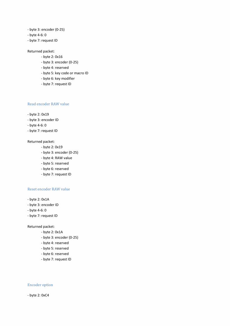
Read encoder RAW value
- byte 2: 0x19
- byte 3: encoder ID
- byte 4-6: 0
- byte 7: request ID
Returned packet:
- byte 2: 0x19
- byte 3: encoder (0-25)
- byte 4: RAW value
- byte 5: reserved
- byte 6: reserved
- byte 7: request ID
Reset encoder RAW value
- byte 2: 0x1A
- byte 3: encoder ID
- byte 4-6: 0
- byte 7: request ID
Returned packet:
- byte 2: 0x1A
- byte 3: encoder (0-25)
- byte 4: reserved
- byte 5: reserved
- byte 6: reserved
- byte 7: request ID
Encoder option
- byte 2: 0xC4

- byte 3: option
- byte 4-6: 0
- byte 7: request ID
if (option > 0)
- bytes 9-33: encoder option set (see above for 'option' values)
Returned packet:
- byte 2: 0xC4
- byte 3-6: reserved
- byte 7: request ID
- bytes 9-33: encoder option get (see above for 'option' values)
Encoder channel A and B pin
- byte 2: 0xC5
- byte 3: option
- byte 4-6: 0
- byte 7: request ID
if (option > 0)
- bytes 9-33: encoder channel A pin set
- bytes 34-58: encoder channel B pin set
Returned packet:
- byte 2: 0xC5
- byte 3-6: reserved
- byte 7: request ID
- bytes 9-33: encoder channel A pin get
- bytes 34-58: encoder channel B pin get
Encoder channel A key code and modifier
- byte 2: 0xC6
- byte 3: option
- byte 4-6: 0
- byte 7: request ID
if (option > 0)
- bytes 9-33: encoder channel A key codes set
- bytes 34-58: encoder channel A key modifiers set
Returned packet:
- byte 2: 0xC6
- byte 3-6: reserved
- byte 7: request ID
- bytes 9-33: encoder channel A key codes get
- bytes 34-58: encoder channel A key modifiers get
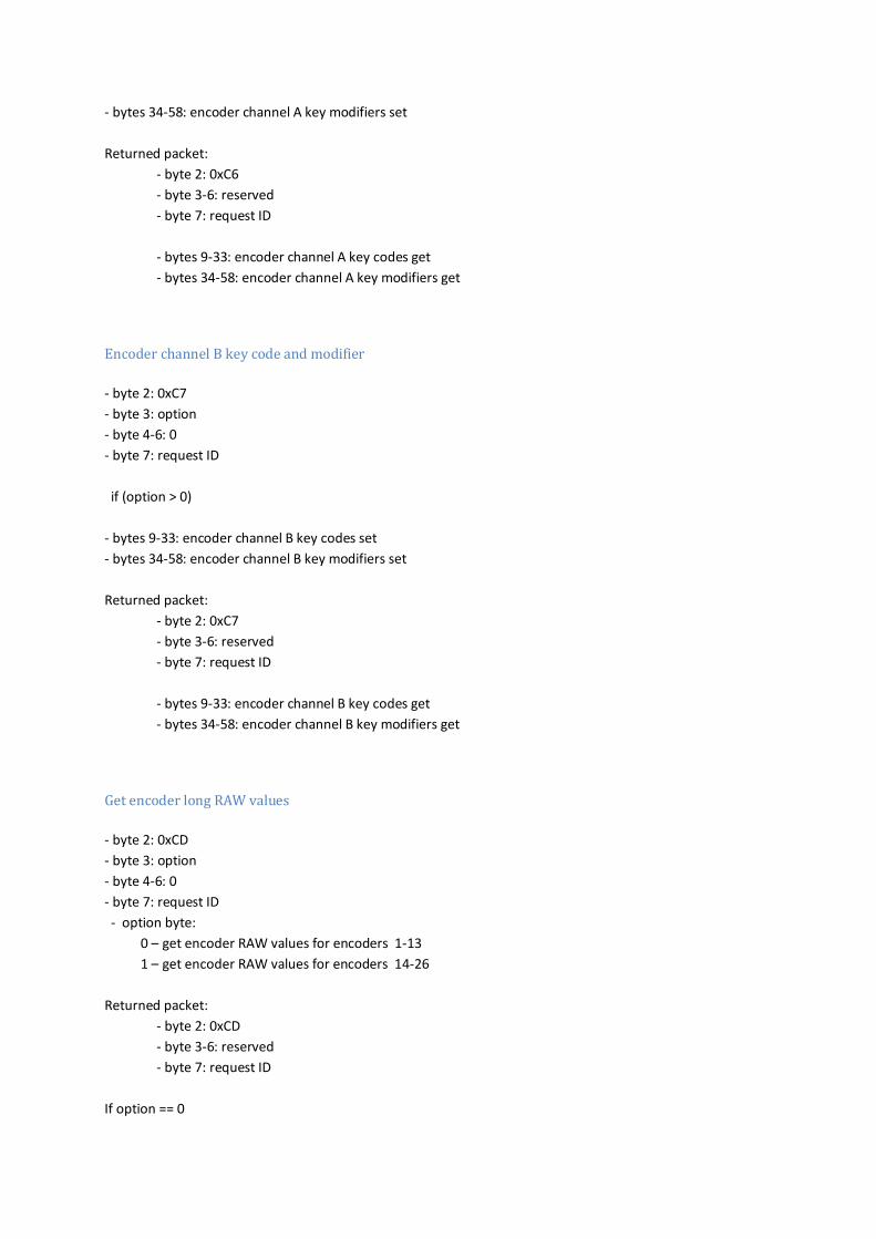
Encoder channel B key code and modifier
- byte 2: 0xC7
- byte 3: option
- byte 4-6: 0
- byte 7: request ID
if (option > 0)
- bytes 9-33: encoder channel B key codes set
- bytes 34-58: encoder channel B key modifiers set
Returned packet:
- byte 2: 0xC7
- byte 3-6: reserved
- byte 7: request ID
- bytes 9-33: encoder channel B key codes get
- bytes 34-58: encoder channel B key modifiers get
Get encoder long RAW values
- byte 2: 0xCD
- byte 3: option
- byte 4-6: 0
- byte 7: request ID
- option byte:
0 – get encoder RAW values for encoders 1-13
1 – get encoder RAW values for encoders 14-26
Returned packet:
- byte 2: 0xCD
- byte 3-6: reserved
- byte 7: request ID
If option == 0
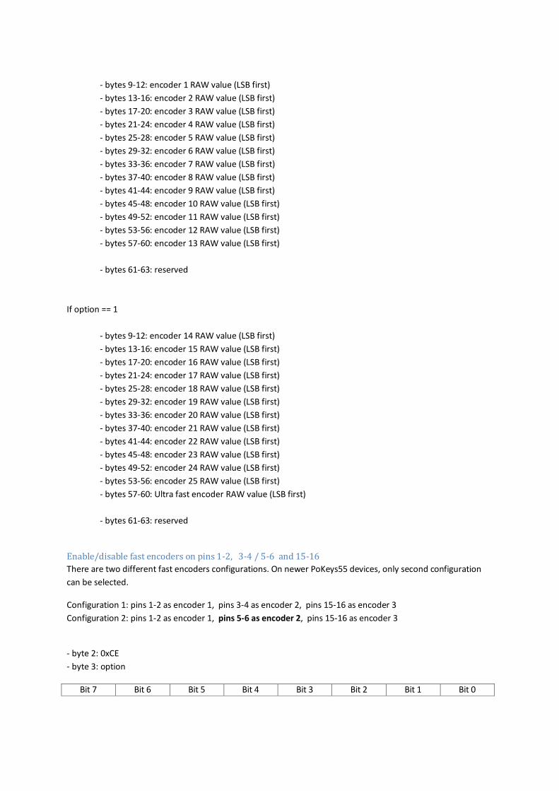
- bytes 9-12: encoder 1 RAW value (LSB first)
- bytes 13-16: encoder 2 RAW value (LSB first)
- bytes 17-20: encoder 3 RAW value (LSB first)
- bytes 21-24: encoder 4 RAW value (LSB first)
- bytes 25-28: encoder 5 RAW value (LSB first)
- bytes 29-32: encoder 6 RAW value (LSB first)
- bytes 33-36: encoder 7 RAW value (LSB first)
- bytes 37-40: encoder 8 RAW value (LSB first)
- bytes 41-44: encoder 9 RAW value (LSB first)
- bytes 45-48: encoder 10 RAW value (LSB first)
- bytes 49-52: encoder 11 RAW value (LSB first)
- bytes 53-56: encoder 12 RAW value (LSB first)
- bytes 57-60: encoder 13 RAW value (LSB first)
- bytes 61-63: reserved
If option == 1
- bytes 9-12: encoder 14 RAW value (LSB first)
- bytes 13-16: encoder 15 RAW value (LSB first)
- bytes 17-20: encoder 16 RAW value (LSB first)
- bytes 21-24: encoder 17 RAW value (LSB first)
- bytes 25-28: encoder 18 RAW value (LSB first)
- bytes 29-32: encoder 19 RAW value (LSB first)
- bytes 33-36: encoder 20 RAW value (LSB first)
- bytes 37-40: encoder 21 RAW value (LSB first)
- bytes 41-44: encoder 22 RAW value (LSB first)
- bytes 45-48: encoder 23 RAW value (LSB first)
- bytes 49-52: encoder 24 RAW value (LSB first)
- bytes 53-56: encoder 25 RAW value (LSB first)
- bytes 57-60: Ultra fast encoder RAW value (LSB first)
- bytes 61-63: reserved
Enable/disable fast encoders on pins 1-2, 3-4 / 5-6 and 15-16
There are two different fast encoders configurations. On newer PoKeys55 devices, only second configuration
can be selected.
Configuration 1: pins 1-2 as encoder 1, pins 3-4 as encoder 2, pins 15-16 as encoder 3
Configuration 2: pins 1-2 as encoder 1, pins 5-6 as encoder 2, pins 15-16 as encoder 3
- byte 2: 0xCE
- byte 3: option
Bit 7 Bit 6 Bit 5 Bit 4 Bit 3 Bit 2 Bit 1 Bit 0

Encoder 3 invert
Encoder 2 invert
Encoder 1 invert
Disable 4x sampling
configuration1
- byte 4-6: 0
- byte 7: request ID
Returned packet:
- byte 2: 0xCD
- byte 3: status
- bytes 4-6: reserved
- byte 7: request ID
- bytes 9-63: reserved
Enable/disable ultra fast encoder
Ultra fast encoder input is supported only on PoKeys56E.
Pins used are:
Pin 8: Phase A input
Pin 12: Phase B input
Pin 13: Index input
- byte 2: 0x1C
- byte 3: enable ultra fast encoder (set to 1 to enable, set to 0 to disable, set to 0xFF to read configuration)
- byte 4: additional options
Bit 7 Bit 6 Bit 5 Bit 4 Bit 3 Bit 2 Bit 1 Bit 0
reserved Enable 4x sampling
Signal mode
Invert direction
- byte 5-6: 0
- byte 7: request ID
Returned packet:
- byte 2: 0x1C
- byte 3: status
- byte 4: additional options as above
- bytes 5-6: reserved
- byte 7: request ID
- bytes 9-63: reserved
1 Set to 1 to enable fast encoders with configuration 1, set to 10 to enable configuration 2, set to 2 to read setup

Digital counters
Get digital counters values
- byte 2: 0xD8
- byte 3: reserved
- byte 4-6: 0
- byte 7: request ID
- bytes 9-21: pin IDs for which the value will be returned
Returned packet:
- byte 2: 0xD8
- byte 3-6: reserved
- byte 7: request ID
- bytes 9-12: counter value 1 (LSB first)
- bytes 13-16: counter value 2 (LSB first)
- bytes 17-20: counter value 3 (LSB first)
- bytes 21-24: counter value 4 (LSB first)
- bytes 25-28: counter value 5 (LSB first)
- bytes 29-32: counter value 6 (LSB first)
- bytes 33-36: counter value 7 (LSB first)
- bytes 37-40: counter value 8 (LSB first)
- bytes 41-44: counter value 9 (LSB first)
- bytes 45-48: counter value 10 (LSB first)
- bytes 49-52: counter value 11 (LSB first)
- bytes 53-56: counter value 12 (LSB first)
- bytes 57-60: counter value 13 (LSB first)
- bytes 61-63: reserved
Get/Set digital counter direction pins
- byte 2: 0xD9
- byte 3: 0 for reading, 1 for writing
- byte 4-6: 0
- byte 7: request ID
- bytes 9-63: direction pin ID for each counter. If pin ID is set to zero, no direction input pin will be used and
counter's value will always increase
Reset digital counters values
- byte 2: 0x1D
- byte 3-6: 0
- byte 7: request ID

Returned packet:
- byte 2: 0x1D
- byte 3-6: 0
- byte 7: request ID
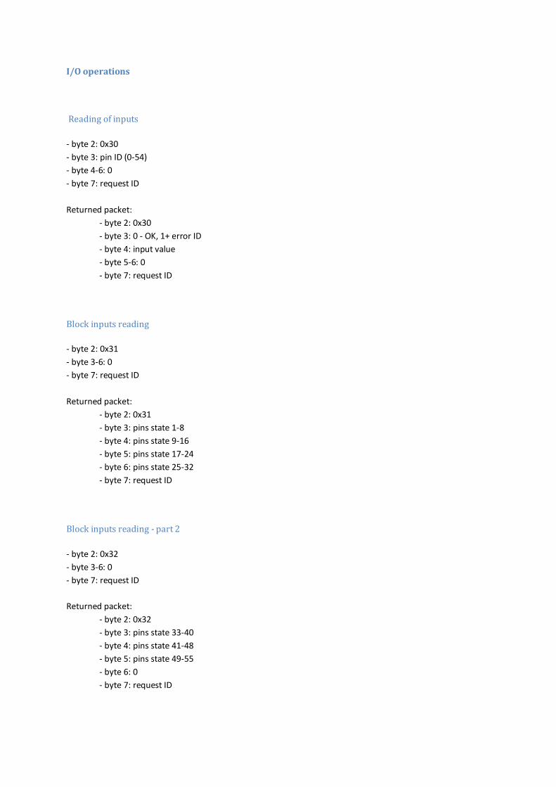
I/O operations
Reading of inputs
- byte 2: 0x30
- byte 3: pin ID (0-54)
- byte 4-6: 0
- byte 7: request ID
Returned packet:
- byte 2: 0x30
- byte 3: 0 - OK, 1+ error ID
- byte 4: input value
- byte 5-6: 0
- byte 7: request ID
Block inputs reading
- byte 2: 0x31
- byte 3-6: 0
- byte 7: request ID
Returned packet:
- byte 2: 0x31
- byte 3: pins state 1-8
- byte 4: pins state 9-16
- byte 5: pins state 17-24
- byte 6: pins state 25-32
- byte 7: request ID
Block inputs reading - part 2
- byte 2: 0x32
- byte 3-6: 0
- byte 7: request ID
Returned packet:
- byte 2: 0x32
- byte 3: pins state 33-40
- byte 4: pins state 41-48
- byte 5: pins state 49-55
- byte 6: 0
- byte 7: request ID

Analog inputs reading:
- byte 2: 0x35
- byte 3: pin ID (42-46)
- byte 4-6: 0
- byte 7: request ID
Returned packet:
- byte 2: 0x35
- byte 3: 0 - OK, 1+ error ID
- byte 4: input value (8-bit)
- byte 5: MSB (2-bit) (4-bit on PoKeys56 devices)
- byte 6: LSB (8-bit)
- byte 7: request ID
Analog inputs block reading - 4x 8bit
- byte 2: 0x36
- byte 3: pin for input 1
- byte 4: pin for input 2
- byte 5: pin for input 3
- byte 6: pin for input 4
- byte 7: request ID
Returned packet:
- byte 2: 0x36
- byte 3: input 1
- byte 4: input 2
- byte 5: input 3
- byte 6: input 4
- byte 7: request ID
Analog inputs block reading - 3x 10bit
- byte 2: 0x37
- byte 3: pin for input 1
- byte 4: pin for input 2
- byte 5: pin for input 3
- byte 6: 0
- byte 7: request ID
Returned packet:
- byte 2: 0x37
- byte 3: MSB 1
- byte 4: MSB 2
- byte 5: MSB 3
- byte 6: LSB 1 LSB 2 LSB 3
- byte 7: request ID
Analog inputs reading – all analog inputs in one command
- byte 2: 0x3A
- byte 3-6: 0
- byte 7: request ID
Returned packet:
- byte 2: 0x3A
- byte 3-6: reserved
- byte 7: request ID
- bytes 9-22: 7 analog inputs values – 2 bytes per input (1 byte for MSB, 1 byte for LSB)
First value is analog input value on pin 41 (on PoKeys56E, value of 0 on PoKeys55), 42 (also 0 on PoKeys55) and
43-47.
Get analog RC filter value
- byte 2: 0x38
- byte 3-6: reserved
- byte 7: request ID
Returned packet:
- byte 2: 0x38
- byte 3-6: RC constant (LSB first)
- byte 7: request ID
Set analog RC filter value
- byte 2: 0x39
- byte 3-6: RC constant (LSB first) – 0 turns filtering off
- byte 7: request ID
Returned packet:
- byte 2: 0x39
- byte 3-6: RC constant (LSB first)
- byte 7: request ID
Outputs setting
- byte 2: 0x40
- byte 3: pin ID (0-54)
- byte 4: value (0-1)
- byte 5-6: 0
- byte 7: request ID
Returned packet:
- byte 2: 0x40
- byte 3: 0 - OK, 1+ error ID
- byte 4-6: 0
- byte 7: request ID
Block outputs writing
code 0x42: set block of outputs 1: byte 3-6: output data (1-32)
code 0x43: set block of outputs 2: byte 3-5: output data (33-55)
Analog ouputs settings
- byte 2: 0x41
- byte 3: pin ID (42)
- byte 4: MSB value (0-255)
- byte 5: LSB value (upper 2 bits)
- byte 6: 0
- byte 7: request ID
Returned packet:
- byte 2: 0x41
- byte 3: 0 - OK, 1+ error ID
- byte 4-6: 0
- byte 7: request ID
Get device status (extended mode - IO, analog, encoders)
- byte 2: 0xCC
- byte 3: option (0 - short packet, 1 - output data is provided)
- byte 4: reserved
- byte 5: reserved
- byte 6: reserved
- byte 7: request ID
if (option > 0)
- bytes 9-12: output data (1-32)
- bytes 13-15: output data (33-55)
- byte 16: analog output MSB
- byte 17: analog output LSB
- bytes 18-63: reserved (0)
Returned packet:
- byte 2: 0x41
- byte 3: 0 - OK, 1+ error ID
- byte 4-6: 0
- byte 7: request ID
- bytes 9-12: input status (1-32)
- bytes 13-15: input status (33-55)
- bytes 16-25: analog 1-5 (MSB+LSB for each input)
- bytes 26-50: 25x 8-bit encoder RAW values
- bytes 51-58: matrix keyboard status (each byte is bit-mapped to a matrix keyboard row)2
- bytes 59-62: ultra fast encoder RAW value
- byte 63: reserved (0)
2 This status only retrieves first part of the matrix keyboard keys (upper 8x8)
Joystick settings
Read joystick configuration
- byte 2: 0x60
- byte 3-6: reserved
- byte 7: request ID
Returned packet:
- byte 2: 0x60
- bytes 3-6: reserved
- byte 7: request ID
- bytes 9-14: joystick axis mapping
- bytes 15-46: joystick buttons mapping
Set joystick configuration
- byte 2: 0x65
- byte 3-6: reserved
- byte 7: request ID
- bytes 9-14: joystick axis mapping3
- bytes 15-46: joystick buttons mapping (1-based pin codes, 0 disables the button, if bit 7 is set, this sets down
Event pin)
Returned packet:
- byte 2: 0x65
- byte 3: 0 - OK, 1+ error ID
- byte 4-6: 0
- byte 7: request ID
Get joystick up Event buttons configuration
- byte 2: 0x61
- byte 3-6: reserved
- byte 7: request ID
Returned packet:
- byte 2: 0x60
- bytes 3-6: reserved
- byte 7: request ID
- bytes 9-14: reserved
3 Set this value to the 1-based pin code (analog inputs have pin codes from 43 to 47), axes have the following order: rotation x, rotation y, x, y, z and throttle

- bytes 15-46: joystick buttons mapping for up event
Set joystick up Event buttons configuration
- byte 2: 0x66
- byte 3-6: reserved
- byte 7: request ID
- bytes 9-14: reserved
- bytes 15-46: joystick buttons up Event mapping (1-based pin codes, 0 disables the up Event button)
Returned packet:
- byte 2: 0x61
- byte 3: 0 - OK, 1+ error ID
- byte 4-6: 0
- byte 7: request ID
Set/Get joystick analog to digital key mapping options
- byte 2: 0x6A
- byte 3: option
- byte 4-6: reserved
- byte 7: request ID
if (option = 0, 1 or 2)
- bytes 9-63: reserved (0)
if (option = 10) - setup for a lower part of the values
- bytes 9-14: mapping type
bit 0: enable key mapping
bit 1: direct key mapping
bit 2: key mapped to macro (KeyCode is macro ID)
bit 3: key mapped to continous macro (same as above, but macro is refiring if input is still active)
bit 4: key repeating (after a delay, the key is being repeatedly fired with a given rate)
bit 5: reserved
bit 6: reserved
bit 7: reserved
- bytes 15-20: key code (or macro ID if mapped to macro)
- bytes 21-26: key modifier
- bytes 27-32: Typematic delay (set in steps of 5 ms – 0 to 1275 ms possible)
- bytes 33-38: pin key repeat rate set (repeat period in 5 ms cycles (plus 1 cycle) – set to 9 (9x 5ms + 1x 5ms =
50ms) to get 20 key presses per second, set to 199 to get 1 key press per second)
- bytes 39-44: pin max key repeat rate set
- bytes 45-63: reserved
if (option = 11) - setup for a upper part of the values
- bytes 9-14: mapping type
bit 0: enable key mapping
bit 1: direct key mapping
bit 2: key mapped to macro (KeyCode is macro ID)
bit 3: key mapped to continous macro (same as above, but macro is refiring if input is still active)
bit 4: key repeating (after a delay, the key is being repeatedly fired with a given rate)
bit 5: reserved
bit 6: reserved
bit 7: reserved
- bytes 15-20: key code (or macro ID if mapped to macro)
- bytes 21-26: key modifier
- bytes 27-32: Typematic delay (set in steps of 5 ms – 0 to 1275 ms possible)
- bytes 33-38: pin key repeat rate set (repeat period in 5 ms cycles (plus 1 cycle) – set to 9 (9x 5ms + 1x 5ms =
50ms) to get 20 key presses per second, set to 199 to get 1 key press per second)
- bytes 39-44: pin max key repeat rate set
- bytes 45-63: reserved
if (option = 2) - band margins setup
- bytes 9-14: lowest value
- bytes 15-20: lower band deadband value
- bytes 21-26: upper band deadband value
- bytes 27-32: highest value
Returned packet:
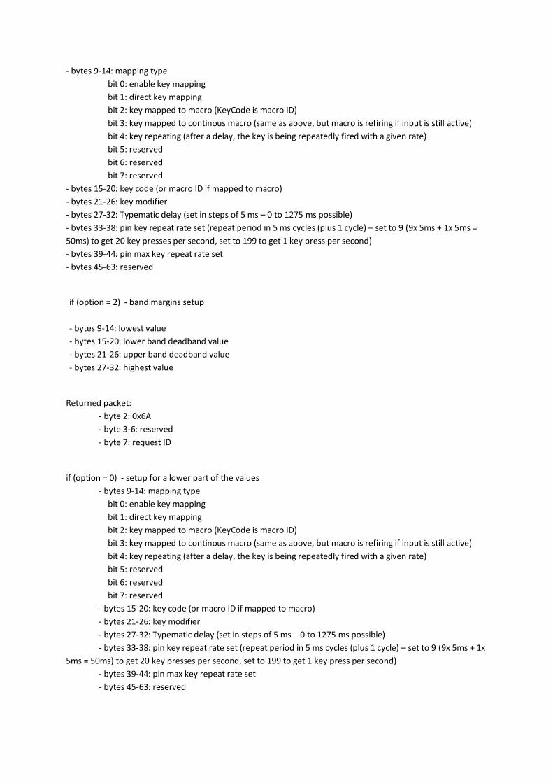
- byte 2: 0x6A
- byte 3-6: reserved
- byte 7: request ID
if (option = 0) - setup for a lower part of the values
- bytes 9-14: mapping type
bit 0: enable key mapping
bit 1: direct key mapping
bit 2: key mapped to macro (KeyCode is macro ID)
bit 3: key mapped to continous macro (same as above, but macro is refiring if input is still active)
bit 4: key repeating (after a delay, the key is being repeatedly fired with a given rate)
bit 5: reserved
bit 6: reserved
bit 7: reserved
- bytes 15-20: key code (or macro ID if mapped to macro)
- bytes 21-26: key modifier
- bytes 27-32: Typematic delay (set in steps of 5 ms – 0 to 1275 ms possible)
- bytes 33-38: pin key repeat rate set (repeat period in 5 ms cycles (plus 1 cycle) – set to 9 (9x 5ms + 1x
5ms = 50ms) to get 20 key presses per second, set to 199 to get 1 key press per second)
- bytes 39-44: pin max key repeat rate set
- bytes 45-63: reserved
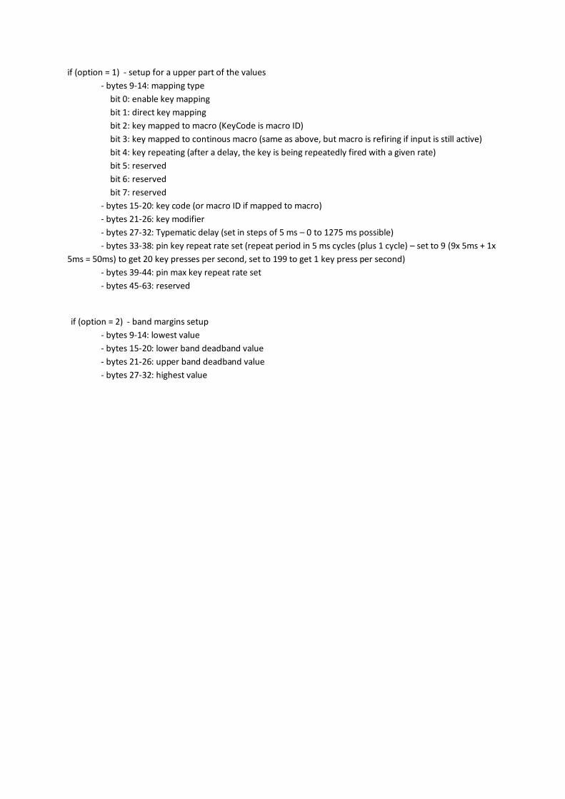
if (option = 1) - setup for a upper part of the values
- bytes 9-14: mapping type
bit 0: enable key mapping
bit 1: direct key mapping
bit 2: key mapped to macro (KeyCode is macro ID)
bit 3: key mapped to continous macro (same as above, but macro is refiring if input is still active)
bit 4: key repeating (after a delay, the key is being repeatedly fired with a given rate)
bit 5: reserved
bit 6: reserved
bit 7: reserved
- bytes 15-20: key code (or macro ID if mapped to macro)
- bytes 21-26: key modifier
- bytes 27-32: Typematic delay (set in steps of 5 ms – 0 to 1275 ms possible)
- bytes 33-38: pin key repeat rate set (repeat period in 5 ms cycles (plus 1 cycle) – set to 9 (9x 5ms + 1x
5ms = 50ms) to get 20 key presses per second, set to 199 to get 1 key press per second)
- bytes 39-44: pin max key repeat rate set
- bytes 45-63: reserved
if (option = 2) - band margins setup
- bytes 9-14: lowest value
- bytes 15-20: lower band deadband value
- bytes 21-26: upper band deadband value
- bytes 27-32: highest value

Macros
Create macro
- byte 2: 0x90
- byte 3: reserved
- byte 4: macro length
- byte 5: reserved
- byte 6: reserved
- byte 7: request ID
Returned packet:
- byte 2: 0x90
- byte 3: macro ID
- byte 4: macro length
- byte 5: 0 - OK, 1+ error ID
- byte 6: reserved
- byte 7: request ID
Modify macro
- byte 2: 0x91
- byte 3: macro ID
- byte 4: new length
- byte 5: reserved
- byte 6: reserved
- byte 7: request ID
Returned packet:
- byte 2: 0x91
- byte 3: macro ID
- byte 4: new length
- byte 5: 0 - OK, 1+ error ID
- byte 6: reserved
- byte 7: request ID
Delete macro
- byte 2: 0x92
- byte 3: macro ID
- byte 4: reserved
- byte 5: reserved
- byte 6: reserved
- byte 7: request ID
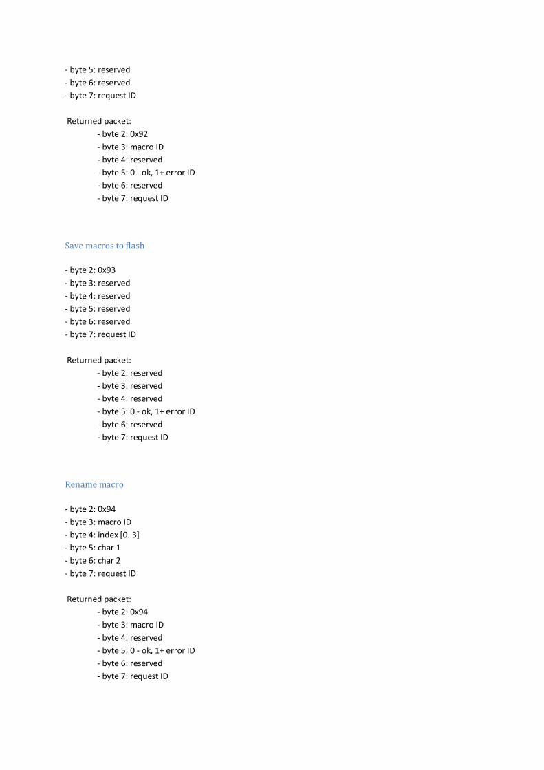
Returned packet:
- byte 2: 0x92
- byte 3: macro ID
- byte 4: reserved
- byte 5: 0 - ok, 1+ error ID
- byte 6: reserved
- byte 7: request ID
Save macros to flash
- byte 2: 0x93
- byte 3: reserved
- byte 4: reserved
- byte 5: reserved
- byte 6: reserved
- byte 7: request ID
Returned packet:
- byte 2: reserved
- byte 3: reserved
- byte 4: reserved
- byte 5: 0 - ok, 1+ error ID
- byte 6: reserved
- byte 7: request ID
Rename macro
- byte 2: 0x94
- byte 3: macro ID
- byte 4: index [0..3]
- byte 5: char 1
- byte 6: char 2
- byte 7: request ID
Returned packet:
- byte 2: 0x94
- byte 3: macro ID
- byte 4: reserved
- byte 5: 0 - ok, 1+ error ID
- byte 6: reserved
- byte 7: request ID

Transfer macro
- byte 2: 0x95
- byte 3: macro ID
- byte 4: index
- byte 5: key code
- byte 6: key modifier
- byte 7: request ID
Returned packet:
- byte 2: 0x95
- byte 3: macro ID
- byte 4: reserved
- byte 5: 0 - ok, 1+ error ID
- byte 6: reserved
- byte 7: request ID
Get macro length
- byte 2: 0x96
- byte 3: macro ID
- byte 4: reserved
- byte 5: reserved
- byte 6: reserved
- byte 7: request ID
Returned packet:
- byte 2: 0x96
- byte 3: macro ID
- byte 4: macro length
- byte 5: 0 - ok, 1+ error ID
- byte 6: reserved
- byte 7: request ID
Get macro name
- byte 2: 0x97
- byte 3: macro ID
- byte 4: index [0..3]
- byte 5: reserved
- byte 6: reserved
- byte 7: request ID
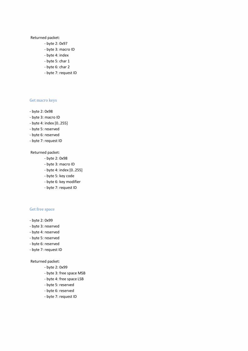
Returned packet:
- byte 2: 0x97
- byte 3: macro ID
- byte 4: index
- byte 5: char 1
- byte 6: char 2
- byte 7: request ID
Get macro keys
- byte 2: 0x98
- byte 3: macro ID
- byte 4: index [0..255]
- byte 5: reserved
- byte 6: reserved
- byte 7: request ID
Returned packet:
- byte 2: 0x98
- byte 3: macro ID
- byte 4: index [0..255]
- byte 5: key code
- byte 6: key modifier
- byte 7: request ID
Get free space
- byte 2: 0x99
- byte 3: reserved
- byte 4: reserved
- byte 5: reserved
- byte 6: reserved
- byte 7: request ID
Returned packet:
- byte 2: 0x99
- byte 3: free space MSB
- byte 4: free space LSB
- byte 5: reserved
- byte 6: reserved
- byte 7: request ID
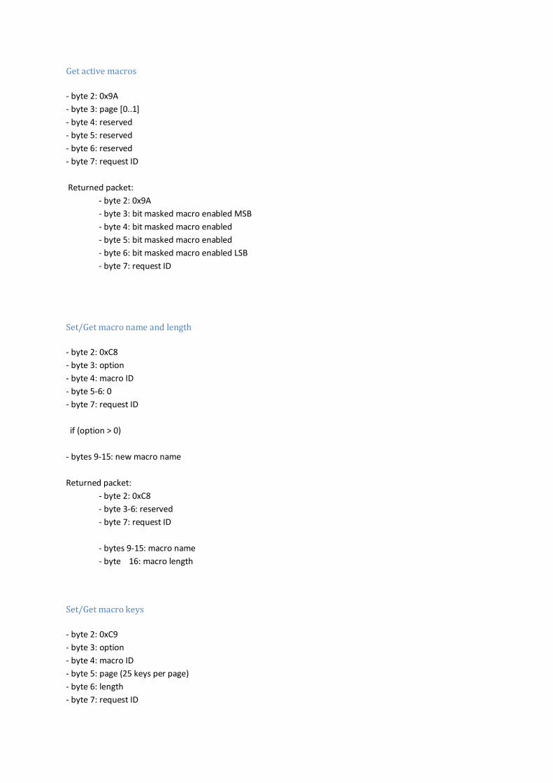
Get active macros
- byte 2: 0x9A
- byte 3: page [0..1]
- byte 4: reserved
- byte 5: reserved
- byte 6: reserved
- byte 7: request ID
Returned packet:
- byte 2: 0x9A
- byte 3: bit masked macro enabled MSB
- byte 4: bit masked macro enabled
- byte 5: bit masked macro enabled
- byte 6: bit masked macro enabled LSB
- byte 7: request ID
Set/Get macro name and length
- byte 2: 0xC8
- byte 3: option
- byte 4: macro ID
- byte 5-6: 0
- byte 7: request ID
if (option > 0)
- bytes 9-15: new macro name
Returned packet:
- byte 2: 0xC8
- byte 3-6: reserved
- byte 7: request ID
- bytes 9-15: macro name
- byte 16: macro length
Set/Get macro keys
- byte 2: 0xC9
- byte 3: option
- byte 4: macro ID
- byte 5: page (25 keys per page)
- byte 6: length
- byte 7: request ID

if (option > 0)
- bytes 9-58: key+modifier pairs
- bytes 59-63: reserved (0)
Returned packet:
- byte 2: 0xC9
- byte 3-6: reserved
- byte 7: request ID
- bytes 9-58: key+modifier pairs
- bytes 59-63: reserved (0)
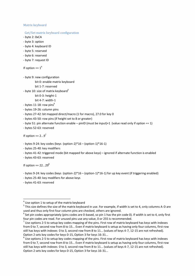
Matrix keyboard
Get/Set matrix keyboard configuration
- byte 2: 0xCA
- byte 3: option
- byte 4: keyboard ID
- byte 5: reserved
- byte 6: reserved
- byte 7: request ID
If option == 14
- byte 9: new configuration
bit 0: enable matrix keyboard
bit 1-7: reserved
- byte 10: size of matrix keyboard5
bit 0-3: height-1
bit 4-7: width-1
- bytes 11-18: row pins6
- bytes 19-26: column pins
- bytes 27-42: bit mapped direct/macro (1 for macro), 27.0 for key 0
- bytes 43-50: row pins (if height set to 8 or greater)
- byte 51: pin alternate function enable – pinID (must be input)+1 (value read only if option == 1)
- bytes 52-63: reserved
If option == 2...97
- bytes 9-24: key codes (keys (option-2)*16 – (option-1)*16-1)
- bytes 25-40: key modifiers
- bytes 41-42: triggered mode (bit mapped for above keys) – ignored if alternate function is enabled
- bytes 43-63: reserved
If option == 22...298
- bytes 9-24: key codes (keys (option-2)*16 – (option-1)*16-1) for up key event (if triggering enabled)
- bytes 25-40: key modifiers for above keys
- bytes 41-63: reserved
4 Use option 1 to setup of the matrix keyboard
5 This size defines the size of the matrix keyboard in use. For example, if width is set to 4, only columns A-D are
used and thus only first four column pins are checked, others are ignored. 6 Set pin codes appropriately (pins codes are 0-based, so pin 1 has the pin code 0). If width is set to 4, only first
four pin codes are read. For unused pins use any value, 0 or 255 is recommended. 7 Use options 2-5 to setup key codes mapping of the pins. First row of matrix keyboard has keys with indexes
from 0 to 7, second row from 8 to 15... Even if matrix keyboard is setup as having only four columns, first row still has keys with indexes 0 to 3, second row from 8 to 11... (values of keys 4-7, 12-15 are not refreshed). Option 2 sets key codes for keys 0-15, Option 3 for keys 16-31... 8 Use options 2-5 to setup key codes mapping of the pins. First row of matrix keyboard has keys with indexes from 0 to 7, second row from 8 to 15... Even if matrix keyboard is setup as having only four columns, first row still has keys with indexes 0 to 3, second row from 8 to 11... (values of keys 4-7, 12-15 are not refreshed). Option 2 sets key codes for keys 0-15, Option 3 for keys 16-31...

Returned packet:
- byte 2: 0xCA
- byte 3: keyboard ID
- byte 4-6: reserved
- byte 7: request ID
If option < 129
- byte 9: new configuration
bit 0: enable matrix keyboard
bit 1-7: reserved
- byte 10: size of matrix keyboard
bit 0-3: height-1
bit 4-7: width-1
- bytes 11-18: row pins
- bytes 19-26: column pins
- bytes 27-42: bit mapped direct/macro (1 for macro), 27.0 for key 0
- bytes 43-50: row pins (if height set to 8 or greater)
- byte 51: pin alternate function enable – pinID (must be input)+1 (value read only if option == 1)
- bytes 52-63: reserved
If option == 12..1910
- bytes 9-24: key codes (keys (option-12)*16 – (option-11)*16-1)
- bytes 25-40: key modifiers
- bytes 41-42: triggered mode
- bytes 43-63: reserved
If option == 32..3911
- bytes 9-24: key codes (keys (option-12)*16 – (option-11)*16-1) for up key event
- bytes 25-40: key modifiers
- bytes 41-63: reserved
If option == 20
- bytes 9-24: matrix keyboard status (whole 16x8 matrix keyboard)
9 Use option less than 12 to retrieve the configuration of the matrix keyboard. If option is used, that is not
previously defined for setup of matrix keyboard, settings are only read, none are set. 10 Retrieve key codes for keys. Look above for description for options 2-5. This options do not change the setup of matrix keyboard. 11 Retrieve key codes for keys. Look above for description for options 2-5. This options do not change the setup of matrix keyboard.
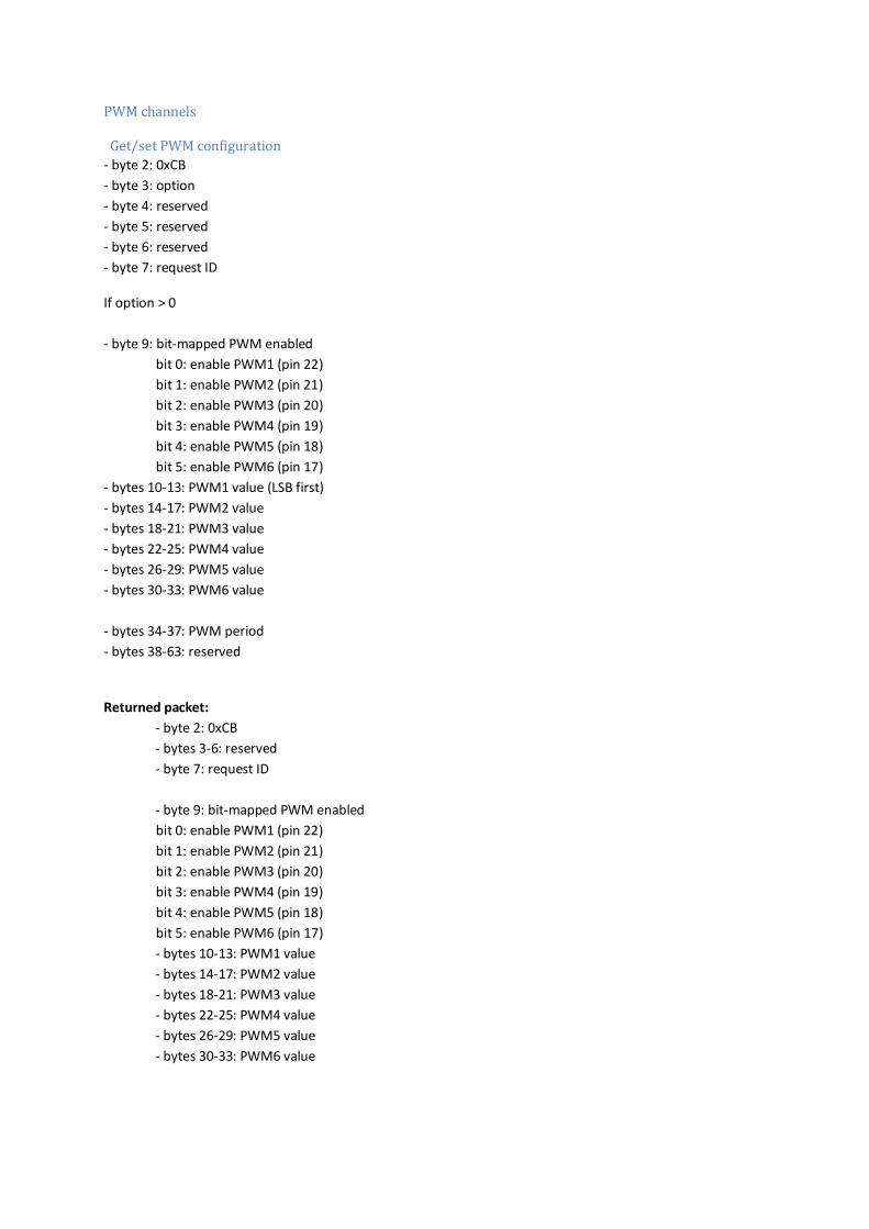
PWM channels
Get/set PWM configuration
- byte 2: 0xCB
- byte 3: option
- byte 4: reserved
- byte 5: reserved
- byte 6: reserved
- byte 7: request ID
If option > 0
- byte 9: bit-mapped PWM enabled
bit 0: enable PWM1 (pin 22)
bit 1: enable PWM2 (pin 21)
bit 2: enable PWM3 (pin 20)
bit 3: enable PWM4 (pin 19)
bit 4: enable PWM5 (pin 18)
bit 5: enable PWM6 (pin 17)
- bytes 10-13: PWM1 value (LSB first)
- bytes 14-17: PWM2 value
- bytes 18-21: PWM3 value
- bytes 22-25: PWM4 value
- bytes 26-29: PWM5 value
- bytes 30-33: PWM6 value
- bytes 34-37: PWM period
- bytes 38-63: reserved
Returned packet:
- byte 2: 0xCB
- bytes 3-6: reserved
- byte 7: request ID
- byte 9: bit-mapped PWM enabled
bit 0: enable PWM1 (pin 22)
bit 1: enable PWM2 (pin 21)
bit 2: enable PWM3 (pin 20)
bit 3: enable PWM4 (pin 19)
bit 4: enable PWM5 (pin 18)
bit 5: enable PWM6 (pin 17)
- bytes 10-13: PWM1 value
- bytes 14-17: PWM2 value
- bytes 18-21: PWM3 value
- bytes 22-25: PWM4 value
- bytes 26-29: PWM5 value
- bytes 30-33: PWM6 value
- bytes 34-37: PWM period
- bytes 38-63: reserved
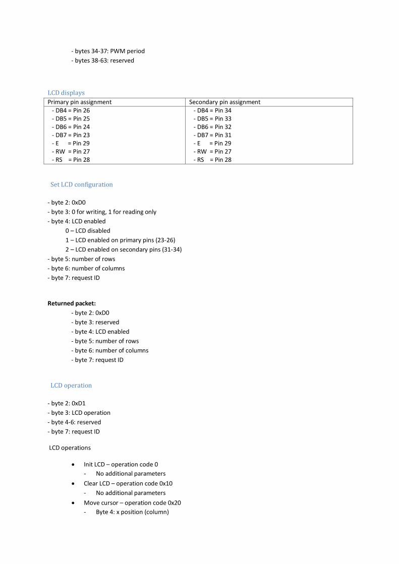
LCD displays
Primary pin assignment Secondary pin assignment
- DB4 = Pin 26 - DB5 = Pin 25 - DB6 = Pin 24 - DB7 = Pin 23 - E = Pin 29 - RW = Pin 27 - RS = Pin 28
- DB4 = Pin 34 - DB5 = Pin 33 - DB6 = Pin 32 - DB7 = Pin 31 - E = Pin 29 - RW = Pin 27 - RS = Pin 28
Set LCD configuration
- byte 2: 0xD0
- byte 3: 0 for writing, 1 for reading only
- byte 4: LCD enabled
0 – LCD disabled
1 – LCD enabled on primary pins (23-26)
2 – LCD enabled on secondary pins (31-34)
- byte 5: number of rows
- byte 6: number of columns
- byte 7: request ID
Returned packet:
- byte 2: 0xD0
- byte 3: reserved
- byte 4: LCD enabled
- byte 5: number of rows
- byte 6: number of columns
- byte 7: request ID
LCD operation
- byte 2: 0xD1
- byte 3: LCD operation
- byte 4-6: reserved
- byte 7: request ID
LCD operations
Init LCD – operation code 0
- No additional parameters
Clear LCD – operation code 0x10
- No additional parameters
Move cursor – operation code 0x20
- Byte 4: x position (column)
- Byte 5: y position (row)
Print to LCD – operation code 0x30
- Bytes 9-29: string to be printed on screen (up to 20 characters, \0 terminated)
Put character to LCD – operation code 0x31
- Byte 9: character code
Define custom character – operation code 0x40
- Byte 9: character code
- Bytes 10-17: character data
Entry mode set – operation code 0x50
- Byte 9: cursor move direction (1 – increment, 0 – decrement)
- Byte 10: display shift on/off
Display on/off control – operation code 0x60
- Byte 9: display on/off
- Byte 10: cursor on/off
- Byte 11: cursor blinking on/off
Returned packet:
- byte 2: 0xD1
- byte 3-6: reserved
- byte 7: request ID
Matrix LED display operations
Matrix LED display pins are fixed due to hardware design. On PoKeys55 device (pin numbers for PoKeys
prototype design are given in parenthesis), pins used are
Display 1:
- Pin 9 (10): serial data
- Pin 10 (11): output register clock
- Pin 11 (12): serial clock
Display 2:
- Pin 23 (23): serial data
- Pin 24 (24): output register clock
- Pin 25 (25): serial clock
Get/set Matrix LED display configuration
- byte 2: 0xD5
- byte 3: option12
- byte 4: matrix LED enabled
bit 0: enable display 1
bit 1: enable display 2
- byte 5: display 1 size
bits 0-3: number of rows (1...8)
bits 4-7: number of columns (1...8)
- byte 6: display 2 size
bits 0-3: number of rows (1...8)
bits 4-7: number of columns (1...8)
- byte 7: request ID
Returned packet:
- byte 2: 0xD5
- byte 3: reserved
- byte 4: matrix LED enabled
- byte 5: display 1 size
- byte 6: display 2 size
- byte 7: request ID
12
To set the configuration, set option byte to 0, else only reading operation will commence
Update matrix LED display
- byte 2: 0xD6
- byte 3: action
1 - update whole display 1 (ignoring row and column bytes)
5 - set pixel at row,column on display 1 (ignoring row data bytes 9-16)
6 - clear pixel at row,column on display 1
11 - update whole display 2 (ignoring row and column bytes)
15 - set pixel at row,column on display 2 (ignoring row data bytes 9-16)
16 - clear pixel at row,column on display 2
- byte 4: row13
- byte 5: column14
- byte 6: reserved
- byte 7: request ID
- byte 9-16: row data (LSB bit of each byte is assigned to a pixel on left of a row)
- bytes 17-63: reserved
Returned packet:
- byte 2: 0xD6
- bytes 3-6: reserved
- byte 7: request ID
PoExtBus functionality
PoExtBus enables to extend number of PoKeys55 outputs for 80. This is acomplished using up to 10 daisy-
chained 8-bit shift registers with latches. Bit 0 of byte 0 is sent first, followed by bits 1-7 then bits 0-7 of byte
1... If shorter chains of shift registers are used, use only the highest bytes (in case only one shift register is used,
only use byte 9 to send data).
Connector option 0 (only on PoKeys56E): PoExtBus has a dedicated connector on PoKeys56 board. This option
enables this connector
Pins used are (PoKeys55 and PoKeys56) – connector option 1
- Pin code 34 (35): serial clock
- Pin code 35 (36): serial data
- Pin code 36 (37): output register clock
13 Row and column indexes are 0-based. 14
Row and column indexes are 0-based.

Set PoExtBus settings
- byte 2: 0xDA
- byte 3: PoExtBus option (set to 1 to enable PoExtBus, set to 0 to disable and set to 2 to read the state)
- byte 4: connector selection (only on PoKeys56E)
- bytes 5-6: reserved
- byte 7: request ID
- bytes 9-18: data bytes
Returned packet:
- byte 2: 0xDA
- byte 3: PoExtBus status
- byte 4: Connector selection
- byte 5-6: reserved
- byte 7: request ID
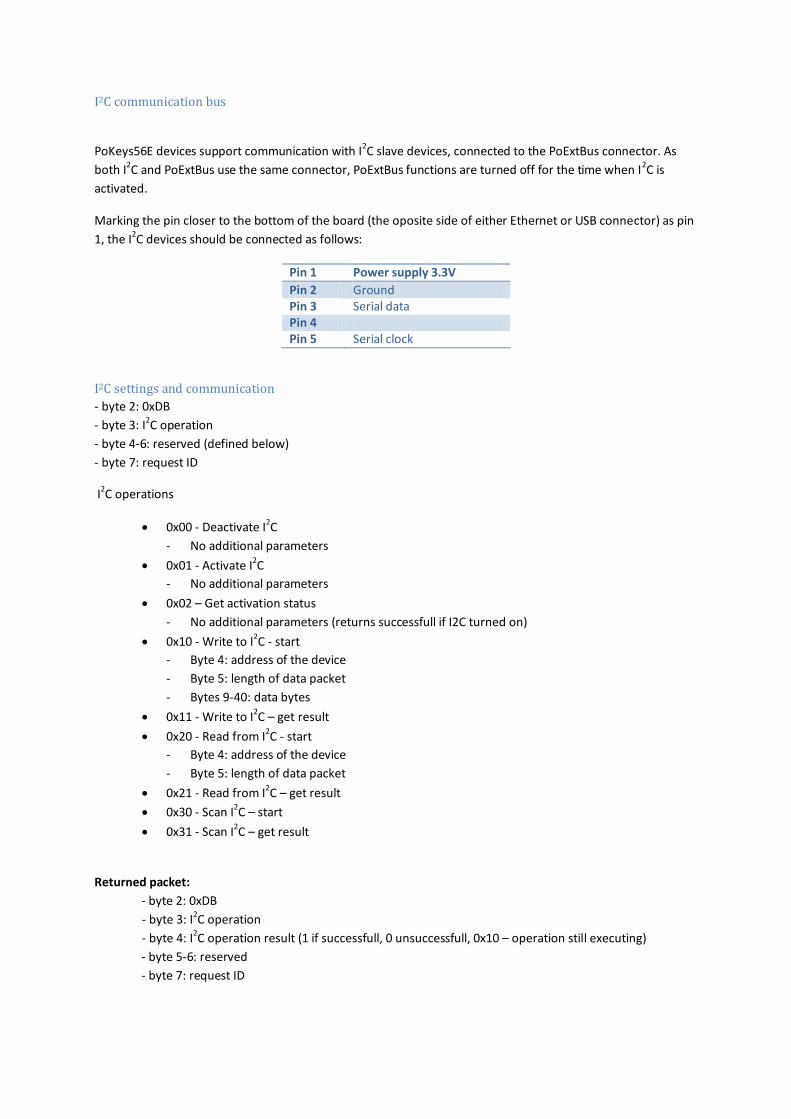
I2C communication bus
PoKeys56E devices support communication with I2C slave devices, connected to the PoExtBus connector. As
both I2C and PoExtBus use the same connector, PoExtBus functions are turned off for the time when I2C is
activated.
Marking the pin closer to the bottom of the board (the oposite side of either Ethernet or USB connector) as pin
1, the I2C devices should be connected as follows:
Pin 1 Power supply 3.3V
Pin 2 Ground Pin 3 Serial data Pin 4 Pin 5 Serial clock
I2C settings and communication
- byte 2: 0xDB
- byte 3: I2C operation
- byte 4-6: reserved (defined below)
- byte 7: request ID
I2C operations
0x00 - Deactivate I2C
- No additional parameters
0x01 - Activate I2C
- No additional parameters
0x02 – Get activation status
- No additional parameters (returns successfull if I2C turned on)
0x10 - Write to I2C - start
- Byte 4: address of the device
- Byte 5: length of data packet
- Bytes 9-40: data bytes
0x11 - Write to I2C – get result
0x20 - Read from I2C - start
- Byte 4: address of the device
- Byte 5: length of data packet
0x21 - Read from I2C – get result
0x30 - Scan I2C – start
0x31 - Scan I2C – get result
Returned packet:
- byte 2: 0xDB
- byte 3: I2C operation
- byte 4: I2C operation result (1 if successfull, 0 unsuccessfull, 0x10 – operation still executing)
- byte 5-6: reserved
- byte 7: request ID

I2C operations
0x21 - Read from I2C – get result
- Byte 9: operation result (copied from byte 4)
- Byte 10: data length
- Bytes 11-42: data bytes
0x31 - Scan I2C – get result
- Byte 9: operation result (copied from byte 4)
- Bytes 10-25: bit encoded result (if bit 0 of byte 10 is set, I2C device with the address of 0x00
was detected)
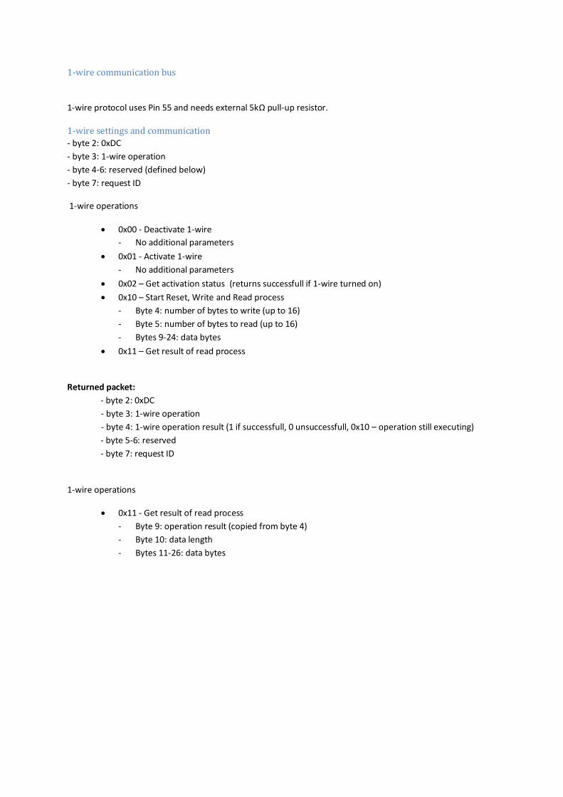
1-wire communication bus
1-wire protocol uses Pin 55 and needs external 5kΩ pull-up resistor.
1-wire settings and communication
- byte 2: 0xDC
- byte 3: 1-wire operation
- byte 4-6: reserved (defined below)
- byte 7: request ID
1-wire operations
0x00 - Deactivate 1-wire
- No additional parameters
0x01 - Activate 1-wire
- No additional parameters
0x02 – Get activation status (returns successfull if 1-wire turned on)
0x10 – Start Reset, Write and Read process
- Byte 4: number of bytes to write (up to 16)
- Byte 5: number of bytes to read (up to 16)
- Bytes 9-24: data bytes
0x11 – Get result of read process
Returned packet:
- byte 2: 0xDC
- byte 3: 1-wire operation
- byte 4: 1-wire operation result (1 if successfull, 0 unsuccessfull, 0x10 – operation still executing)
- byte 5-6: reserved
- byte 7: request ID
1-wire operations
0x11 - Get result of read process
- Byte 9: operation result (copied from byte 4)
- Byte 10: data length
- Bytes 11-26: data bytes
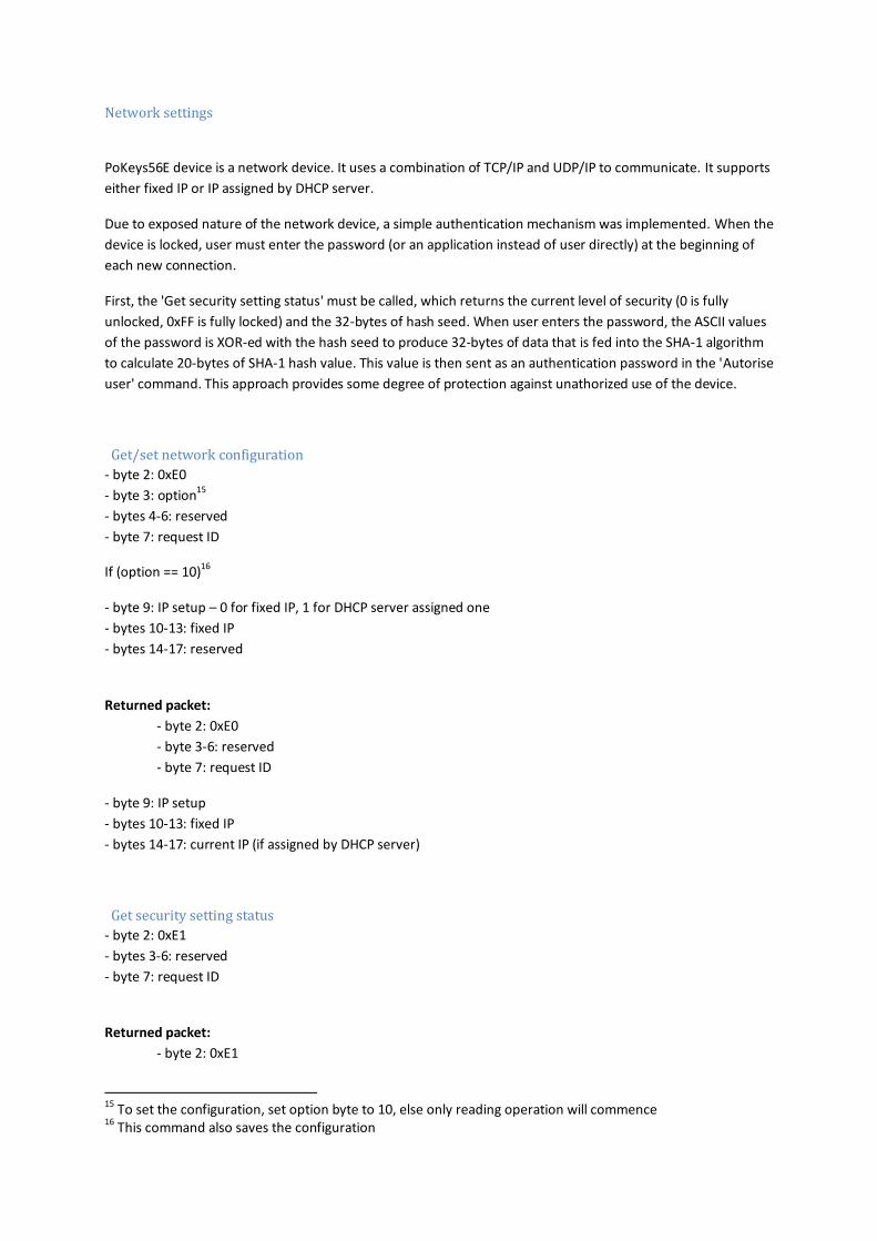
Network settings
PoKeys56E device is a network device. It uses a combination of TCP/IP and UDP/IP to communicate. It supports
either fixed IP or IP assigned by DHCP server.
Due to exposed nature of the network device, a simple authentication mechanism was implemented. When the
device is locked, user must enter the password (or an application instead of user directly) at the beginning of
each new connection.
First, the 'Get security setting status' must be called, which returns the current level of security (0 is fully
unlocked, 0xFF is fully locked) and the 32-bytes of hash seed. When user enters the password, the ASCII values
of the password is XOR-ed with the hash seed to produce 32-bytes of data that is fed into the SHA-1 algorithm
to calculate 20-bytes of SHA-1 hash value. This value is then sent as an authentication password in the 'Autorise
user' command. This approach provides some degree of protection against unathorized use of the device.
Get/set network configuration
- byte 2: 0xE0
- byte 3: option15
- bytes 4-6: reserved
- byte 7: request ID
If (option == 10)16
- byte 9: IP setup – 0 for fixed IP, 1 for DHCP server assigned one
- bytes 10-13: fixed IP
- bytes 14-17: reserved
Returned packet:
- byte 2: 0xE0
- byte 3-6: reserved
- byte 7: request ID
- byte 9: IP setup
- bytes 10-13: fixed IP
- bytes 14-17: current IP (if assigned by DHCP server)
Get security setting status
- byte 2: 0xE1
- bytes 3-6: reserved
- byte 7: request ID
Returned packet:
- byte 2: 0xE1
15 To set the configuration, set option byte to 10, else only reading operation will commence 16
This command also saves the configuration
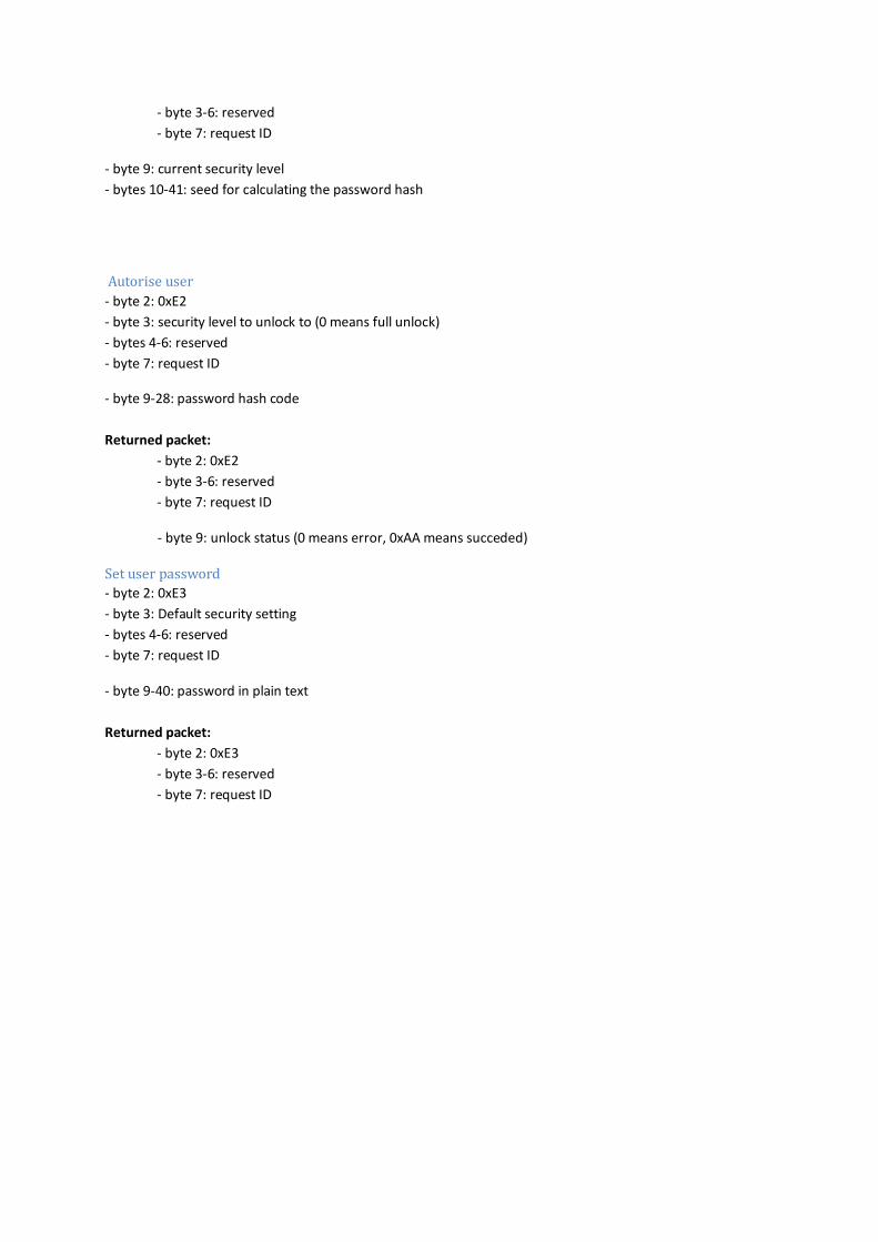
- byte 3-6: reserved
- byte 7: request ID
- byte 9: current security level
- bytes 10-41: seed for calculating the password hash
Autorise user
- byte 2: 0xE2
- byte 3: security level to unlock to (0 means full unlock)
- bytes 4-6: reserved
- byte 7: request ID
- byte 9-28: password hash code
Returned packet:
- byte 2: 0xE2
- byte 3-6: reserved
- byte 7: request ID
- byte 9: unlock status (0 means error, 0xAA means succeded)
Set user password
- byte 2: 0xE3
- byte 3: Default security setting
- bytes 4-6: reserved
- byte 7: request ID
- byte 9-40: password in plain text
Returned packet:
- byte 2: 0xE3
- byte 3-6: reserved
- byte 7: request ID
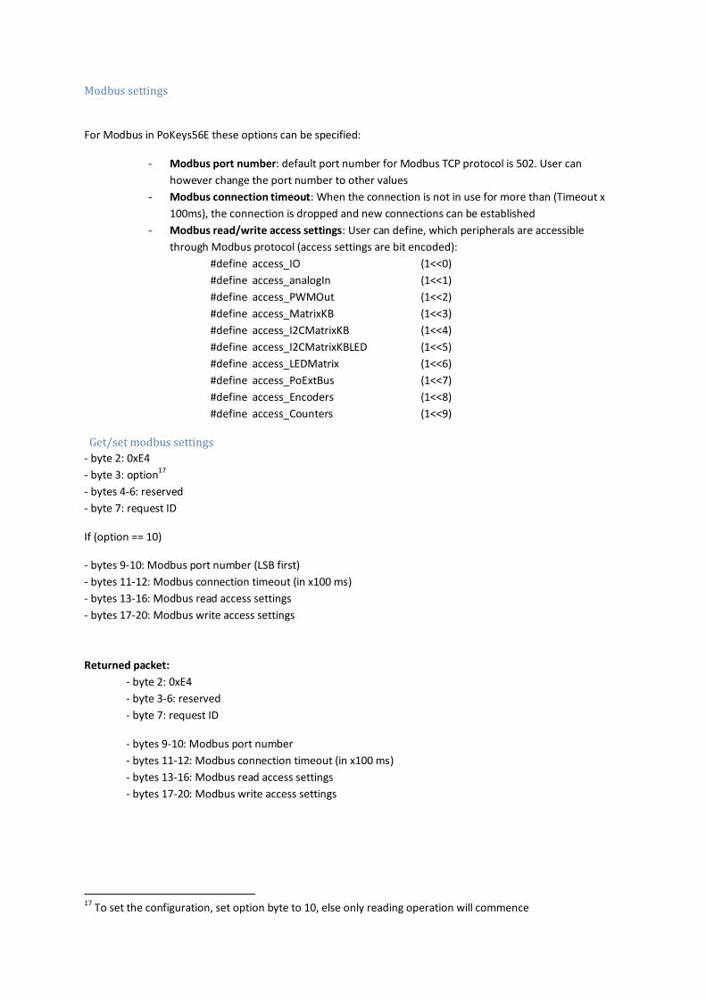
Modbus settings
For Modbus in PoKeys56E these options can be specified:
- Modbus port number: default port number for Modbus TCP protocol is 502. User can
however change the port number to other values
- Modbus connection timeout: When the connection is not in use for more than (Timeout x
100ms), the connection is dropped and new connections can be established
- Modbus read/write access settings: User can define, which peripherals are accessible
through Modbus protocol (access settings are bit encoded):
#define access_IO (1<<0)
#define access_analogIn (1<<1)
#define access_PWMOut (1<<2)
#define access_MatrixKB (1<<3)
#define access_I2CMatrixKB (1<<4)
#define access_I2CMatrixKBLED (1<<5)
#define access_LEDMatrix (1<<6)
#define access_PoExtBus (1<<7)
#define access_Encoders (1<<8)
#define access_Counters (1<<9)
Get/set modbus settings
- byte 2: 0xE4
- byte 3: option17
- bytes 4-6: reserved
- byte 7: request ID
If (option == 10)
- bytes 9-10: Modbus port number (LSB first)
- bytes 11-12: Modbus connection timeout (in x100 ms)
- bytes 13-16: Modbus read access settings
- bytes 17-20: Modbus write access settings
Returned packet:
- byte 2: 0xE4
- byte 3-6: reserved
- byte 7: request ID
- bytes 9-10: Modbus port number
- bytes 11-12: Modbus connection timeout (in x100 ms)
- bytes 13-16: Modbus read access settings
- bytes 17-20: Modbus write access settings
17
To set the configuration, set option byte to 10, else only reading operation will commence


