IEEE TRANSACTIONS ON ANTENNAS AND PROPAGATION, VOL. 50, NO. 5, MAY 2002 713
Polarimetric Channel Characterization of Foliagefor Performance Assessment of GPS Receivers
Under Tree CanopiesIl-Suek Koh, Associate Member, IEEE,and Kamal Sarabandi, Fellow, IEEE
Abstract—The attenuation, depolarization, and fluctuation ofa microwave signal going through a tree canopy are investigatedby developing a Monte Carlo based coherent scattering model. Inparticular, the model is used to analyze the performance of globalpositioning system (GPS) receivers under tree canopies. Also thefrequency and time-domain channel characteristics of a forestare investigated when a transmitter is outside and a receiver isinside a forest. A fractal algorithm (Lindenmayer system) is usedto generate the structure of coniferous or deciduous trees whosebasic building blocks are arbitrarily oriented finite cylinders,thin dielectric needles, and thin dielectric disks. Attenuation andphase change of the mean field through foliage is accounted forusing Foldy’s approximation. Scattering of the mean field fromindividual tree components and their images in the underlyingground plane are computed analytically and added coherently.Since tree trunks and some branches are large compared to thewavelength and may be in the close proximity of the receiver, aclosed-form and uniform expression for the scattered near-fieldfrom dielectric cylinders is also developed. Monte Carlo simula-tion of field calculation is applied to a cluster of trees in orderto estimate the statistics of the channel parameters, such as theprobability density function (pdf) of the polarization state of thetransmitted field, path loss, and the incoherent scattered power(the second moment of the scattered field), as a function of theobservation point above the ground.
Index Terms—Channel simulation, propagation, vegetation.
I. INTRODUCTION
W ITH the increasing demand for wireless communica-tions, the need for the efficient use of the spectrum is
felt more than ever. Accurate estimation of system requirementssuch as transmitter power, bandwidth, modulation scheme,etc., all depend on the communication channel characteristics.Ground-to-air/satellite communication is a scenario withnumerous civilian and military applications ranging fromsimple voice and data communications to navigation. In thisscenario, characterization of the channel is rather straightfor-ward except for the urban environment or forested areas wheresignificant scattering and shadowing may take place. In thispaper, the problem of channel characterization for a forestedenvironment is considered. Using this model, performance of
Manuscript received June 15, 2001; revised November 15, 2001. This workwas supported in part by the National Science Foundation, under ContactECS-9 979 376 and in part by the U.S. Army Research Office under ContractDAAH04-96-1-0377.
The authors are with the Radiation Laboratory, Department of Electrical En-gineering and Computer Science, The University of Michigan, Ann Arbor, MI48109-2122 USA (e-mail: [email protected]).
Publisher Item Identifier S 0018-926X(02)05458-3.
global positioning system (GPS) receivers under tree canopiesand a narrow pulse transmission through a tree canopy areinvestigated as examples.
The GPS was introduced by the Department of Defense(DoD) primarily for the U.S. military to provide precise esti-mation of position, velocity, and time. Since the early 1980s,the DoD has allowed GPS to be used for civilian applications.Because of the high price of GPS receivers in early years,the application of GPS for commercial purposes was limitedmainly to civil aviation. In recent years, however, mainly withthe rapid development of the integrated circuit, the availabilityof low-cost receivers has significantly broadened the applica-tion domain of the GPS, such as land transportation, surveyingand mapping, agriculture, earth sciences, etc. [1]. Each GPSsatellite transmits a right hand circularly polarizedL-bandsignal at two frequency bands known asL1 (1.575 42 GHz)andL2 (1.2276 GHz). For a commercial use, theL1 signal ismodulated by a pseudo random noise (PRN) code called thecoarse/ccquisition (C/P) code which is a 1023 gold code witha chip rate of 1023 microchips/s (Mcps) and its null-to-nullbandwidth is 2.046 MHz [2]. When this signal reaches theearth’s surface, the level is very weak and therefore the receiverperformance may be severely degraded if a line-of-sight (LOS)transmission is not established.
With the advent of powerful computers, physics-based ap-proaches for predicting deterministic or statistical channel char-acteristics have attained significant prominence in recent years[3]. These models are more comprehensive and can be used fora larger class of scenarios with a high accuracy than traditionalmodels based on measurements or simple diffraction models.However, the physics-based models are complex and not easy touse because of the difficulty of electromagnetic modeling of anenvironment. In this study, the development of a physics-basedchannel model for vegetation canopies is considered. The liter-ature concerning interaction of electromagnetic waves and veg-etation can be categorized into two groups, namely, papers re-lated to radar remote sensing of vegetation [4]–[8] and papers re-lated to communications [9]–[11]. The thrust of remote sensingarticles is on the modeling of vegetation scattering when boththe transmitter and receiver are in the far field region of the il-luminated canopy and the interest is usually in the calculationof the mean backscatter power. In the communication problemwhere the transmitter or receiver, or both, are within the canopy,the field calculations and the mechanisms responsible for thedominant field at the receiver are very different. For example,when both the transmitter and receiver are embedded in the
714 IEEE TRANSACTIONS ON ANTENNAS AND PROPAGATION, VOL. 50, NO. 5, MAY 2002
Fig. 1. The problem geometry where a receiver inside a forest iscommunicating with a transmitter above.
canopy, there is a nonvanishing dominant mean-field at frequen-cies below UHF, which can be attributed to a lateral wave whichpropagates along the canopy-air interface and sheds energy atcritical angle. Mathematically this lateral wave results from thebranch-cut contribution of the spectral representation of a dipolefield in a dielectric slab [9], [10]. Wave propagation over rela-tively long distances at UHF and higher where both the trans-mitter and receiver are embedded in a forest canopy is not pos-sible due to exorbitant propagation path loss. At these frequen-cies either the transmitter or the receiver must be outside thecanopy. Field calculations for this scenario are complicated be-cause of the close proximity of the receiver (transmitter) to rel-atively large scatterers, which can cause significant field atten-uation and fluctuation.
In what follows, development of an accurate model that de-scribes the propagation of electromagnetic waves through fo-liage is considered. In Section II, the overall structure of the co-herent channel model based on a single scattering theory andMonte Carlo simulation is presented. Also, an analytical ap-proximate scattering formulation for an arbitrarily oriented fi-nite dielectric cylinder above a ground plane, which can repre-sent tree trunks and branches, is provided. This new formulationis a building block for the channel model and provides a uniformexpression for the scattered field which is valid for observationpoints near and far from the cylinder. Finally in Section III, nu-merical simulations are presented showing the effects of foliageon the GPS signal. Quantities such as the signal path loss, statis-tics of the received polarization, and the first-order statistics ofthe electric field for both horizontally and vertically polarizedincident waves are calculated. In addition, the effect of the treecanopy on an ultra-wide-band signal is investigated.
II. FORESTMODEL
From electromagnetic scattering point of view, a tree canbe considered as a complex structure composed of a group ofrandomly oriented scatterers structured in a semideterministicfashion with electrical characteristics very much dependent ontheir moisture content. At UHF frequencies and higher, dimen-sions of tree trunk, the primary and secondary branches, or evenleaves and twigs can be much larger than or comparable to thewavelength. Noting that a relatively large cluster of trees aroundan observation point significantly contribute to the total field atthe receiver, field calculations based on brute-force numericaltechniques are not possible at microwave frequencies or higher.
Fig. 2. Global and local coordinate systems for an arbitrarily orientedcylinder. (a) Before the coordinate transformation. (b) After the coordinatetransformation.
Fig. 3. Three geometrical optics (GO) components of the scattered field froma cylinder above the ground plane, along with forward scattered component.
However, if the multiple scattering among branches and leavesis ignored, a single scattering model can be constructed. To a
KOH AND SARABANDI: POLARIMETRIC CHANNEL CHARACTERIZATION OF FOLIAGE 715
Fig. 4. Numerical and analytic evaluation of (e )=(j~r�~r j) dz . (a) Magnitude. (b) Phase.
high degree of accuracy this model can predict the first order sta-tistics of the total field within a forest. This is because throughthe averaging process the dominant portion of the total field (co-herent effect) can survive and the multiple interaction is mini-mized. In modeling the forest, one approach is to distribute thevegetation particles (leaves and branches) uniformly, however,it is found that for frequencies up to about 3 GHz it is impor-tant to preserve the structural information of tree canopies foraccurate prediction of radar backscatter [6]. This effect is ex-pected to be even more important when the observation point iswithin the forest. Basically, not only the coherence of the scat-tered fields from the vegetation structure must be preserved, butalso the near-field effects of lower branches and tree trunks nearthe observation point must be accounted for very accurately.
Fig. 1 shows the geometry of the communication problemwhere a receiver (or a transmitter) embedded in a foliage is com-municating with a transmitter (or a receiver) above the foliagelayer. As the signal passes through the foliage, it experiencesattenuation and scattering which depend on signal parameters
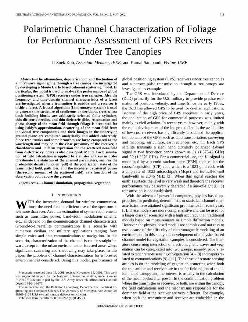
Fig. 5. Comparison of analytic and MoM results of scattered field(E ) froma finite cylinder whose radius is 5 cm and dielectric constant is5+j. The lengthof the finite cylinder is4� and the observation line isz = L=2��= tan�. TMwave is incident at� = 60 and� = 180 . (a) Magnitude. (b) Phase.
such as frequency, polarization, and incidence angle, as well asvegetation attributes such as tree type, density, and height. Asmentioned earlier, to model the interaction of electromagneticwaves with vegetation accurately, tree structures must be mod-eled rather accurately. Considering the number of branches andleaves on a tree and the variability in their sizes and orientations,generating a tree structure can be a very difficult task. This canbe done efficiently by approximating tree structures by fractalgeometries. Here we use a statistical Lindenmayer system [6]in conjunction with botanical properties pertinent to a specifiedtree specie. In this model, the geometry of vegetation particlesare also approximated by canonical geometries such as dielec-tric disks, needles, and layered dielectric cylinders. Each par-ticle in the medium is assumed to be illuminated by the incident
716 IEEE TRANSACTIONS ON ANTENNAS AND PROPAGATION, VOL. 50, NO. 5, MAY 2002
Fig. 6. Comparison of analytic and MoM results of scattered field(E ) froma finite cylinder whose radius is 5 cm and dielectric constant is5+j. The lengthof the finite cylinder is4�, and the observation line isz = L=2 � �= tan �.TE wave is incident at� = 60 , and� = 180 . (a) Magnitude (b) Phase.
wave, attenuated by the foliage along the ray between the par-ticle and the canopy top. The attenuation through the foliageis calculated using Foldy’s approximation [12] and single scat-tering theory is invoked to compute the field scattered from allvegetation particles and their images in the ground plane in thevicinity of the observation point. The total field is then obtainedby adding all scattered field components coherently.
A. A Uniform Near-Field to Far-Field Expression forScattering From Finite Dielectric Cylinders
A building block for simulated fractal trees are finite dielectriccylinders which can be used to represent tree trunks, branches,and twigs. To compute the scattered field from a fractaltree, an analytic or numeric scattering solution is needed.Unfortunately, exact analytical solutions for finite dielectriccylinders do not exist. Numerical methods, of course, can
(a)
(b)
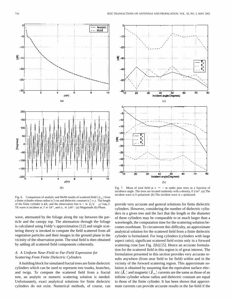
Fig. 7. Mean of total field atz = 1 m under pine trees as a function ofincidence angle. The trees are located randomly with a density, 0.1/m. (a) Theincident wave ish-polarized. (b) The incident wave isv-polarized.
provide very accurate and general solutions for finite dielectriccylinders. However, considering the number of dielectric cylin-ders in a given tree and the fact that the length or the diameterof these cylinders may be comparable to or much larger than awavelength, the computation time for the scattering solution be-comes exorbitant. To circumvent this difficulty, an approximateanalytical solution for the scattered field from a finite dielectriccylinder is formulated. For long cylinders (cylinders with largeaspect ratio), significant scattered field exists only in a forwardscattering cone [see Fig. 2(b)] [5]. Hence an accurate formula-tion for the scattered field in this region is of great interest. Theformulation presented in this section provides very accurate re-sults anywhere (from near field to far field) within and in thevicinity of the forward scattering region. This approximate so-lution is obtained by assuming that the equivalent surface elec-tric and magnetic currents are the same as those of aninfinite cylinder whose radius and dielectric constant are equalto those of the finite cylinder. It has been shown that approxi-mate currents can provide accurate results in the far-field if the
KOH AND SARABANDI: POLARIMETRIC CHANNEL CHARACTERIZATION OF FOLIAGE 717
(a)
(b)
Fig. 8. Standard deviation of total field atz = 1 m under pine trees as afunction of incidence angle. The trees are located randomly with a density,0.1/m . (a) The incident wave ish-polarized. (b) The incident wave isv-polarized.
length of the cylinder is large compared to both wavelength andcylinder radius ( and ), and the angle of incidence withrespect to the cylinder axis is relatively large [4], [5].Analytic expressions for these currents are given by [4], [5]
(1)
(2)
where is the free-space propagation constant, andis the free-space admittance. The terms, , and
are given by
where , andare the th-order Bessel and Hankel function of the first kind,respectively, and theindicates the derivative with respect to theentire argument. Other terms, such as, and are given in[4], [5]. Using these currents, the electric field can be writtenin terms of electric , and magnetic Hertz potentialsusing
(3)
where
(4)
(5)
In situations where the observation point is not in the far-fieldregion of the cylinder, a difficulty arises from the evaluation of
. As will be shown, usingan integral transformation, this integral can be represented byan approximate closed-form formula which retains a high de-gree of accuracy. Using the identity,
[13], the integral is trans-formed to a more appropriate form
where , and , and. Each integral in the above equation can be trans-
718 IEEE TRANSACTIONS ON ANTENNAS AND PROPAGATION, VOL. 50, NO. 5, MAY 2002
formed by following the standard steepest decent method pro-cedure [13], [14] into
where can be 1 or 2, , and . Also
, and .Since the resulting integrand has a singularity atthe integrand must be decomposed into two parts: one thatcontains the singularity and the other one which is regular, thatis
where and is the residue ofat the singularity which is given by
Here the sign is used for , thesign is used for , and
for. Noting that
where
the final expressions for and can be written as
where is the error function [13]–[15].Noting that for large the quantity
, a better approxima-tion for may be written as
(6)
Hence the expression for the electric Hertz potential in (4), canbe written as
(7)
It is not obvious how to carry out the above integral with re-spect to analytically, however if is assumed,an analytical expression can be obtained using the following ap-proximations:
where , and . Similarly
where . Therefore, with the aid ofthe integral relations given in [4], [5], the two integrals in (7)can be evaluated analytically as
(8)
where
KOH AND SARABANDI: POLARIMETRIC CHANNEL CHARACTERIZATION OF FOLIAGE 719
Similarly
(9)
where. Finally, the two Hertz vectors can be expressed
by
According to (3), the scattered electric field can be evaluatedby taking the curl of the approximate closed form expressionsof the Hertz potentials. Noting that the observation point is inthe far field with regard to cylinder diameter thefar-field approximation for the operator is expressed as
where . After somealgebraic manipulation, the complete expression of the electricfield for a finite cylinder may be written as
(10)
Equation (10) is valid for observation points on or near theforward scattering cone. If the observation point is outside thecone (the effect of the pole can be neglected), another equation
for the scattered field can be formulated. Using the asymptoticbehavior of the error function, [15],(6) can be reduced to
Through the same procedure and approximations, a formulationfor the scattered field that is valid outside the forward scatteringcone can be written as
(11)
It is worth mentioning that (10) and (11) can be reduced to theformula derived in [5] for observation points in the near-fieldregion and a formula given in [4] for observation points in thefar-field region. To apply this formulation to a cylinder with ar-bitrary orientation, it is needed to transform the components ofthe incident wave in the global coordinate system , tothe local cylinder coordinate system where -axis isparallel to the cylinder axis. After calculating the scattered fieldcomponents in the local coordinates, they are transformed backto the global coordinate system. This procedure is mathemati-cally expressed by
where is the transformation matrix and is given by
for a cylinder with orientation angles , as is seen inFig. 2.
B. Scattering From Leaves and Needles
The thickness of most broad leaf vegetation (mm) is very small compared to the wavelength at frequenciesup toX band. For these leaves the Rayleigh–Gans approxima-tion [16] is used, which is valid, independent of the leaf surfacedimensions relative to the wavelength. That is so long as theelectric thickness of the leaf is very small, the Rayleigh–Gansapproximation provides accurate results. For leaves where sur-face dimensions are large compared to the wavelength and theirelectric thickness becomes compared to the wavelength, a phys-ical optic approximation [4] is used. This solution is valid forfrequencies atX band and above. A formulation for thin cylin-ders of arbitrary cross section [4] is used to model the scatteringfrom vegetation needles.
720 IEEE TRANSACTIONS ON ANTENNAS AND PROPAGATION, VOL. 50, NO. 5, MAY 2002
(a)
(b)
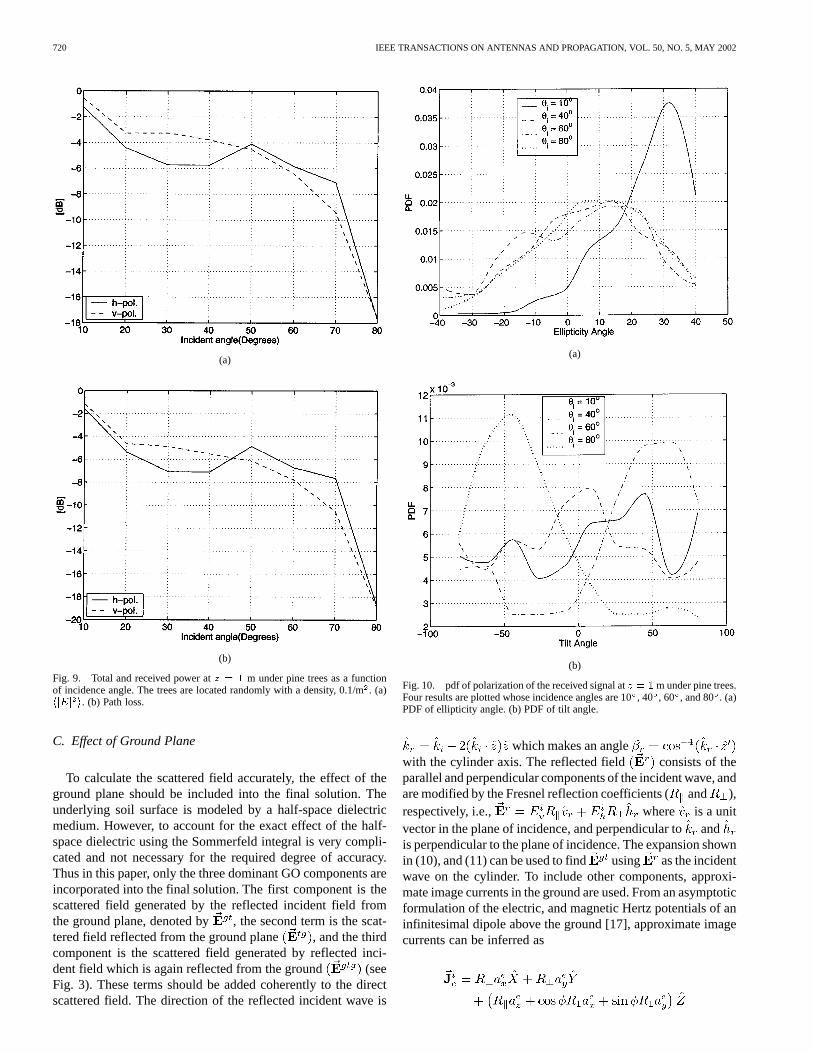
Fig. 9. Total and received power atz = 1 m under pine trees as a functionof incidence angle. The trees are located randomly with a density, 0.1/m. (a)hjEj i. (b) Path loss.
C. Effect of Ground Plane
To calculate the scattered field accurately, the effect of theground plane should be included into the final solution. Theunderlying soil surface is modeled by a half-space dielectricmedium. However, to account for the exact effect of the half-space dielectric using the Sommerfeld integral is very compli-cated and not necessary for the required degree of accuracy.Thus in this paper, only the three dominant GO components areincorporated into the final solution. The first component is thescattered field generated by the reflected incident field fromthe ground plane, denoted by , the second term is the scat-tered field reflected from the ground plane , and the thirdcomponent is the scattered field generated by reflected inci-dent field which is again reflected from the ground (seeFig. 3). These terms should be added coherently to the directscattered field. The direction of the reflected incident wave is
(a)
(b)
Fig. 10. pdf of polarization of the received signal atz = 1m under pine trees.Four results are plotted whose incidence angles are 10, 40 , 60 , and 80 . (a)PDF of ellipticity angle. (b) PDF of tilt angle.
which makes an anglewith the cylinder axis. The reflected field consists of theparallel and perpendicular components of the incident wave, andare modified by the Fresnel reflection coefficients (and ),respectively, i.e., where is a unitvector in the plane of incidence, and perpendicular toandis perpendicular to the plane of incidence. The expansion shownin (10), and (11) can be used to find using as the incidentwave on the cylinder. To include other components, approxi-mate image currents in the ground are used. From an asymptoticformulation of the electric, and magnetic Hertz potentials of aninfinitesimal dipole above the ground [17], approximate imagecurrents can be inferred as
KOH AND SARABANDI: POLARIMETRIC CHANNEL CHARACTERIZATION OF FOLIAGE 721
(a)
(b)
Fig. 11. Mean of total field atz = 1m under deciduous trees as a function ofincidence angle. The trees are located randomly with a density, 0.1/m, and theresults include the effects of leaves. (a) The incident wave ish-polarized. (b)The incident wave isv-polarized.
where the currents above the ground plane are given as, and . Here
,and is the dielectric constant of the ground. The reflectioncoefficients, , and and other quantities such as ,and can be assumed constant because in the far-field re-gion, the variation of these quantities is very small. The angleat which these Fresnel reflection coefficients are calculated isobtained by using the line connecting the image point to the ob-servation point, that is, if denotes the observation point and
represents the image of the source point this angle is definedas . To compute , and
(a)
(b)
Fig. 12. Standard deviation of total field atz = 1 m under deciduous treesas a function of incidence angle. The trees are located randomly with a density,0.1/m , and the results include the effects of leaves. (a) The incident wave ish-polarized. (b) The incident wave isv-polarized.
, (10), and (11) can now be used but the termsandmust be modified as
where .
III. N UMERICAL SIMULATION
In this section, the validity of the approximate formulationsfor the scattered field of a finite cylinder are being examined. Anumber of approximations were used to derive the integral ex-pression given by (6). Fig. 4 shows the comparison between the
722 IEEE TRANSACTIONS ON ANTENNAS AND PROPAGATION, VOL. 50, NO. 5, MAY 2002
Fig. 13. Total and received power atz = 1 m under deciduous trees as afunction of incidence angle. The trees are located randomly with a density,0.1/m . ‘�’ and ‘ ’ are results that include the effects of leaves. (a)hjEj i(b) Path loss.
two results from an exact numerical integration and the analyticformulation, (6). In this comparison, is and the observa-tion point is at and . As can be seenthe two results are in excellent agreement over the entire regionof comparison. The next two (Figs. 5 and 6) show the accuracyof (10) when a TM, and TE waves are incident on alongcylinder with dielectric constant, , and a radius, cm,at , and . For the TM wave incidence case,only one principal component is plotted for brevity, butthe same accuracy is observed for the other component. AMoM solution [11] is used for exact calculation of the scatteredfield. It is shown that the two results are in good agreement.The accuracy of the approximate formulation (10) degrades asthe ratio (radius/length) is increased.
The developed forest channel model is used to demon-strate performance assessment of GPS receivers placed underconiferous and deciduous canopies. For these simulations the
Fig. 14. pdf of polarization of the received signal atz = 1m under deciduoustrees. Four results are plotted whose incidence angles are 10, 40 , 60 , and80 . (a) pdf of ellipticity angle. (b) pdf of tilt angle.
frequency is set at 1.575 42 GHz and the polarization is chosento be right-hand circular (RHCP). For the following simulationsa receiver is placed 1 m above a ground plane having a soil mois-ture content which consists of 50% sand and 10%clay. At this GPS frequency the soil dielectric constant is calcu-lated to be [6]. To derive the field statisticsand forest channel properties, a Monte Carlo simulation is car-ried out using 400 realizations. To account for near-field effects,10 trees randomly located around the receiver are included in thesimulations. First, a relatively young red pine stand with averagetree height of 9.5 m and the density of 0.1 trees/mis considered.The mean and standard deviation of the total field (incidentre-flected scattered) are shown in Figs. 7, and 8, respectively, forboth - and -polarized incident waves as function of incidenceangle. As the incidence angle increases, the field is more attenu-ated as expected and small cross-polarized components are ob-served. In Fig. 7(a), the mean-field jumps approximately 10 dB
KOH AND SARABANDI: POLARIMETRIC CHANNEL CHARACTERIZATION OF FOLIAGE 723
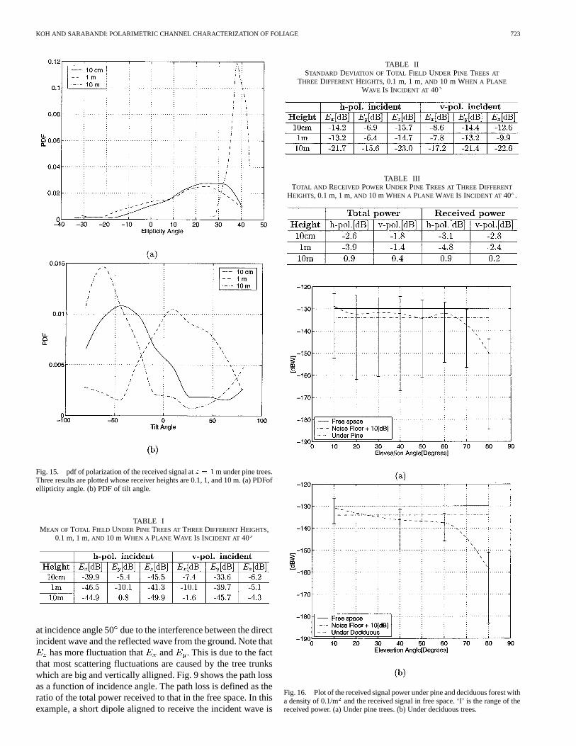
Fig. 15. pdf of polarization of the received signal atz = 1m under pine trees.Three results are plotted whose receiver heights are 0.1, 1, and 10 m. (a) PDFofellipticity angle. (b) PDF of tilt angle.
TABLE IMEAN OF TOTAL FIELD UNDER PINE TREES ATTHREE DIFFERENTHEIGHTS,
0.1 m, 1 m,AND 10 m WHEN A PLANE WAVE IS INCIDENT AT 40
at incidence angle 50due to the interference between the directincident wave and the reflected wave from the ground. Note that
has more fluctuation that and . This is due to the factthat most scattering fluctuations are caused by the tree trunkswhich are big and vertically alligned. Fig. 9 shows the path lossas a function of incidence angle. The path loss is defined as theratio of the total power received to that in the free space. In thisexample, a short dipole aligned to receive the incident wave is
TABLE IISTANDARD DEVIATION OF TOTAL FIELD UNDER PINE TREES AT
THREE DIFFERENT HEIGHTS, 0.1 m, 1 m,AND 10 m WHEN A PLANE
WAVE IS INCIDENT AT 40
TABLE IIITOTAL AND RECEIVED POWER UNDER PINE TREES ATTHREE DIFFERENT
HEIGHTS, 0.1 m, 1 m,AND 10 m WHEN A PLANE WAVE IS INCIDENT AT 40 .
Fig. 16. Plot of the received signal power under pine and deciduous forest witha density of 0.1/m and the received signal in free space. ‘I’ is the range of thereceived power. (a) Under pine trees. (b) Under deciduous trees.
724 IEEE TRANSACTIONS ON ANTENNAS AND PROPAGATION, VOL. 50, NO. 5, MAY 2002
used as the receiver antenna. Next, we examine the statistics ofthe polarization of the received signal. Polarization of a wave ischaracterized by two parameters, the ellipticity angleand thetilt angle, [18]. At the receiver both the vertical and horizontalcomponents of the electric field in a plane perpendicular to thedirection of incidence are calculated and for whichand areevaluated. In this simulation the polarization of incidence waveis assumed be right hand circular polarization. A Monte Carlosimulation is used to estimate the pdf ofand for the red pinestand. It is shown that as the incidence angle is increased thepolarization of the received signal is modified, however, it re-mains always righthanded. A similar Monte Carlo simulation iscarried out for deciduous forest stand that consist of red maples.A tree density of 0.1/mand average height of 17 m and trunkdiameter of 20 cm is chosen. This stand has a dry biomass of107 kg/tree. Simulations for both foliated and defoliated treesare performed. Figs. 11, and 12 show the mean field and stan-dard deviation for a receiver 1 m above the ground for a foliatedstand as a function of incidence angle. The same jump phenom-enon is observed in the mean field due to the same interferenceas the pine tree case. Similar to the pine forest simulation, thestandard deviation is comparable to or larger than the mean field,and the level of the cross polarized filed is relatively low. Thepath loss is also calculated and shown in Fig. 13. As the inci-dence angle increases, the-polarized wave is more attenuatedbecause the path length increases in the trunk layer where scat-terers are aligned mostly along-axis. Whereas the number ofleaves (of the order of 12 000 per a typical tree) is higher than thenumber of branches and twigs , scattering from leavescan be ignored as their typical dimension (7 cm) is small com-pared to the wavelength. However, leaves can cause consider-able attenuation. Fig. 14 shows the pdf of ellipticity angle andtilt angle for a receiver 1 m above ground under the red maplestand. It is shown that the incident wave approached a linearwave ( -polarized).
Next, we examine the effect of receiver height on the field at-tenuation, fluctuation, and depolarization for the red pine standat 40 incidence. Tables I and II show the three components ofmean field and its standard deviation for the two principal po-larizations. It is shown that the ratio of standard deviation tomean field decreases as the receiver height is increased. Table IIIshows the copolarized path loss as a function of receiver height.The pdf of polarization state as a function of receiver heightfor incidence angle 40are shown in Fig. 15. The polarizationat m is almost the same as that of the incident wave(RHCP).
Now let us consider a GPS receiver at a height of 1 m aboveground embedded in the red pine. It is assumed that polarizationof the antenna is RHCP and has a free space gain of 0 dBi. Thepower received by such receiver in free space is dBW onthe earth surface [2]. This signal level is below the thermal noisepower at the receiver if it were not for the processing gain ofabout 30 dB for the 1023 chip code length of the GPS receiver[19]. Considering the receiver bandwidth is MHz,the noise power is calculated from
dBW
Fig. 17. Frequency response of a pine forest over 1–GHz bandwidth (1–2GHz) when a plane wave is incident 40. The receiver is 1 m over the groundplane. Effect of 20 trees near a receiver. (a)E . (b)E . (c)E .
KOH AND SARABANDI: POLARIMETRIC CHANNEL CHARACTERIZATION OF FOLIAGE 725
Fig. 18. Time-domain response of a narrow pulse transmission through a pineforest. The pulse is incident at 40. (a)E . (b)E . (c)E .
This calculation assumes a receiver noise figure of 1.5 dB andthe noise power associated with the antenna temperature is ig-nored. However, it should be pointed out that the antenna tem-
perature operating under foliage can be significantly different(higher) than that without foliage. Fig. 16(a) shows the meanpower received by the GPS receiver under red pine forest. Alsoshown in this figure (the vertical bar) is a power range of the sim-ulation and the received power in the absence of foliage, and thethermal noise power plus 10 dB (thresholdS/N). It is shown thatthe mean signal power is above the threshold for incidence an-gles below 70, however, strong power fluctuations may hamperreceiver signal lock on a given satellite. Fig. 16(b) shows theperformance of the same receiver below the red maple stand.Here receiver power fluctuation is less since the lower branchesare farther from the receivers. In both cases reliable, operationcannot be guaranteed. To remedy this problem more transmitterpower (by a factor of 15 dB) is needed.
Last we examine the performance of a wide-band time do-main communication system. Time-domain modulation usingvery narrow pulses is being considered for military applications,since it minimizes evesdropping and provides antijamming ca-pability. A signal occupying a bandwidth 1–2 GHz is consid-ered. Again a receiver is considered to be 1 m above the groundplane in the red pine stand. An incidence angle of 40is as-sumed. Fig. 17 shows the frequency response of three compo-nents (for a given realization of tree) for both vertical and hor-izontal incident wave. Strong spectral field fluctuations are aresult of multipath caused by strong scatterers in the channel.The Fourier transform of these responses provides the time do-main response of the channel. Fig. 18 shows the time domainresponse for the three received field components assuming theincident field has a Gaussian envelope for both the vertical andhorizontal incident waves.
IV. CONCLUSION
A physics-based channel estimation model for a forested en-vironment is developed. This model is appropriate when ei-ther the transmitter or receiver is within the canopy and theother is outside. Realistic tree structures are constructed usinga fractal algorithm and scattering from individual tree compo-nents are calculated and added coherently. An accurate approx-imate uniform near-field to far-field scattering solution for di-electric cylinders representing branches and tree trunks is alsodeveloped and incorporated into the tree model. Monte Carlosimulations are carried out in order to estimate the statistics ofthe channel behavior, such as path loss, coherence bandwidth,field fluctuation, etc. In specifics, performance of GPS receiversunder foliage is evaluated and it is shown that the signal attenu-ation, depolarization, and field fluctuation hamper proper oper-ation of a receiver under both coniferous and deciduous standswith heights as low as 10 m. The same model is used to assessthe performance of wide-band communications.
REFERENCES
[1] P. Enge and P. Misra, “Special issue on global positioning system,”Proc.IEEE, vol. 87, pp. 3–15, Jan. 1999.
[2] Global Positioning System Standard Positioning Service Signal Specifi-cation, 1995.
[3] H. L. Bertoni,Radio Propagation for Modern Wireless Systems. UpperSaddle River, NJ: Prentice-Hall, 2000.
[4] K. Sarabandi, “Electromagnetic Scattering from Vegetation Canopies,”Ph.D dissertation, University of Michigan, Ann Arbor, 1989.
726 IEEE TRANSACTIONS ON ANTENNAS AND PROPAGATION, VOL. 50, NO. 5, MAY 2002
[5] K. Sarabandi, P. F. Polatin, and F. T. Ulaby, “Monte Carlo simulationof scattering from a layer of vertical cylinder,”IEEE Trans. AntennasPropagat., vol. 41, pp. 465–475, Apr. 1993.
[6] Y. C. Lin and K. Sarabandi, “Monte Carlo coherent scattering modelfor forest canopies using fractal-generated trees,”IEEE Trans. Geosci.Remote Sensing, vol. 37, pp. 440–451, 1999.
[7] M. A. Karam, A. K. Fung, and Y. M. M. Antar, “Electromagnetic wavescattering from some vegetation samples,”IEEE Trans. Geosci. RemoteSensing, vol. 26, pp. 799–808, 1988.
[8] P. L. E. Uslenghi, “The backscattering radar cross section of long thindielectric bodies of revolution on a metal plane,”Can. J. Phys., vol. 43,pp. 1164–1167, 1965.
[9] T. Tamir, “On radio-wave propagation in forest environments,”IEEETrans. Antennas Propagat., vol. AP-15, pp. 806–817, Nov. 1967.
[10] K. Sarabandi and I. Koh, “Effect of canopy-air interface roughness onHF-UHF wave propagation in forest,”IEEE Trans. Antennas Propagat.,vol. 50, pp. 111–121, Feb. 2002.
[11] , “A complete physics-based channel parameter simulation forwave propagation in a forest environment,”IEEE Trans. AntennasPropagat., vol. 49, pp. 260–271, Feb. 2001.
[12] L. L. Foldy, “The multiple scattering of waves,”Phys. Rev., vol. 67, pp.107–119, 1945.
[13] L. B. Felsen and N. Marcuvitz,Radiation and Scattering ofWaves. New York: Prentice-Hall, 1973.
[14] R. E. Collin,Field Theory of Guided Waves. New York: IEEE Press,1990.
[15] Handbook of Mathematical Functions, Dover, New York, 1965.[16] R. Schiffer and K. O. Thielheim, “Light scattering by dielectric needles
and disks,”J. Appl. Phys., vol. 50, no. 4, pp. 2476–2483, Apr. 1979.[17] R. E. Collin and F. J. Zucker,Antenna Theory. New York: McGraw-
Hill, 1969.[18] F. T. Ulaby, R. K. Moore, and A. K. Fung,Microwave Remote Sensing
Active and Passive. Norwood, MA: Arthech House, 1982.[19] J. G. Proakis,Digital Communications. New York: McGraw-Hill,
1989.
Il-Suek Koh (S’01–A’02) was born in Korea. Hereceived the B.S. and M.S. degrees in electronicsengineering from Yonsei University, Seoul, Korea,in 1992 and 1994, respectively. He is currentlyworking toward the Ph.D. degree at the Universityof Michigan, Ann Arbor.
In 1994, he joined LG Electronics Ltd. as anAssistant Research Engineer. His research interestsare theoretical modeling of wireless communicationchannel, multibody problems, and numericaltechniques for electrically large objects.
Kamal Sarabandi (S’87-M’90-SM’9-F’00) re-ceived the B.S. degree in electrical engineering fromSharif University of Technology, Tehran, Iran, in1980. He received the M.S.E. degree in electricalengineering, the M.S. degree in mathematics, andthe Ph.D. degree in electrical engineering, from theUniversity of Michigan, Ann Arbor, in 1986, 1989,and 1989, respectively.
He is the Director of the Radiation Laboratoryand Professor in the Department of ElectricalEngineering and Computer Science, University
of Michigan. His research areas of interest include electromagnetic wavepropagation, antennas, and microwave and millimeter-wave radar remotesensing. He has served as the Principal Investigator on many projects sponsoredby NASA, JPL, ARO, ONR, ARL, NSF, DARPA, and numerous industries. Hehas published many book chapters and more than 90 papers in refereed journalson electromagnetic scattering, random media modeling, wave propagation,antennas, microwave measurement techniques, radar calibration, inversescattering problems, and microwave sensors. He has more than 170 papers andinvited presentations in national and international conferences and symposiaon similar subjects.
Dr. Sarabandi is a member of the IEEE Geoscience and Remote Sensing So-ciety (GRSS) ADCOM, Chairman of the Awards Committee of the IEEE GRSS,and a member of IEEE Technical Activities Board Awards Committee. He isserving as the Associate Editor of the IEEE TRANSACTIONS ONANTENNAS AND
PROPAGATION and the IEEE SENSORSJOURNAL. He is also a member of Com-mission F of URSI and of the Electromagnetic Academy. He is listed inAmer-ican Men & Women of Science, Who’s Who in America, andWho’s Who inElectromagnetics. He was the recipient of the prestigious Henry Russel Awardfrom the Regent of the University of Michigan (the highest honor the Univer-sity of Michigan bestows on a faculty member at the assistant or associate level).In 1999, he received a GAAC Distinguished Lecturer Award from the GermanFederal Ministry for Education, Science, and Technology. He was also a recip-ient of a 1996 Teaching Excellence Award from the EECS Department of theUniversity of Michigan. In the past several years, joint papers presented by hisstudents at a number of symposia (IEEE AP’95, ’97, ’00, ’01, IEEE MTT-S’01,and IEEE IGARSS’99) have received student prize paper awards.