P1000i P2000i Polaris Power™ For your nearest Polaris dealer, call 1-800-POLARIS or visit www.polaris.com Polaris Sales Inc., 2100 Hwy 55, Medina, MN 55340 Phone 1-888-704-5290 Part No. 9924212 Rev 01 Failure to properly follow the instructions and precautions in this manual can result in property damage, serious injury or DEATH!
Transcript
P1000iP2000i
Polaris Power™
For your nearest Polaris dealer, call 1-800-POLARIS or visit www.polaris.comPolaris Sales Inc., 2100 Hwy 55, Medina, MN 55340Phone 1-888-704-5290 Part No. 9924212 Rev 01
Failure to properly follow the instructions and precautions in this manual can result in property damage, serious injury or DEATH!
Thank you for purchasing a Polaris PowerTM Generator,
and welcome to our world-wide family of Polaris owners.
Be sure to visit us on-line at www.polaris.com for the
latest news, new product introductions, upcoming events,
career opportunities, and more.
Here at Polaris we proudly produce an exciting line ofutility and recreational products.
• Snowmobiles
• All-terrain vehicles (ATVs)
• RANGER® utility vehicles
• RANGER® RZR utility vehicles
• Low emission vehicles (LEVs)
• Victory® Motorcycles
• Polaris PowerTM Generator
We believe Polaris sets a standard of excellence for all
utility vehicles, recreational vehicles, and power
equipment manufactured in the world today. Many years
of experience have gone into the engineering, design,
and development of your Polaris machine.
For safe and enjoyable operation of your generator, be
sure to follow the instructions and recommendations in
this owner’s manual. Your manual contains instructions
for minor maintenance, but information about major
repairs is outlined in the Polaris Service Manual and
should be performed only by a factory certified Master
Service Dealer® (MSD) Technician.
Your Polaris dealer knows your generator best and is
interested in your total satisfaction. Be sure to return to
your dealership for all of your service needs during and
after the warranty period.
We also take great pride in our complete line of apparel,parts, and accessories, available through our on-linestore at www.purepolaris.com. Have your accessoriesand clothing delivered right to your door!
The engine exhaust from this product contains
chemicals known to the State of California to cause
cancer, birth defects, or other reproductive harm.
Intended Use
The Polaris PowerTM Generator is intended to supply
power for appliances. Such items include, but are not
limited to:
• Furnace fans
• Sump pumps
• Dishwashers
• Hotplates / Stoves
• Lamps
• Fans
• Washing machines
• Garage door openers
• Water heaters
• Televisions
• Refrigerators
• Computers
Appliances that use more than the recommended amount(see Specifications Page) of combined powerconsumption should not be connected to this generator.
2
INTRODUCTION
Safety Precautions
Failure to follow recommended precautions and
procedures could result in severe injury or death.
Always heed all safety precautions and follow all
operation, inspection, and maintenance procedures
outlined in this manual.
Please read the Polaris P1000i/P2000i GeneratorTM
Owner’s Manual. This manual contains information
essential to safe operation and proper maintenance of the
generator. Anyone who operates the generator must read
the owner’s manual before operating the generator.
Read and understand the information found in the safety
section, and have manual on hand when operating the
generator. Following the safety precautions and
procedures will ensure a safe operating experience.
Understand and follow all inspection and maintenance
procedures outlined in this manual. Following these
procedures will ensure that the generator remains in safe
operating conditions at all times.
Warnings, Cautions, and Notices
Signal Words and Safety Terms
The following signal words and symbols appear
throughout this manual. Your safety, and the safety of
others, is involved when these words and symbols are
used. Become familiar with their meaning before reading
the manual.
A safety alert warning indicates a hazardous
situation which, if not avoided, may result in death or
serious injury.
A safety alert caution indicates a hazardous situation
which, if not avoided, may result in minor or
moderate injury.
A notice is used to address practices not related to
physical injury.
IMPORTANT: Key reminders during assembly,
disassembly, and inspection of components.
NOTE: Key information to clarify instructions.
ALCOHOL OR DRUG USE
Operating the generator after consuming alcohol or
drugs could adversely affect operator judgment.
Never consume alcohol or drugs before or while
operating the generator.
Identification Numbers and Locations
Record your generator’s identification numbers in thespace provided. The model and serial number decal islocated on the bottom of the side panel.
MODEL NUMBER:_________________________________
SERIAL NUMBER:
_____________________________________________
PURCHASE DATE: ____________________________
PURCHASE LOCATION:
____________________________________________
P1000i :to the right of the engine oil dipstick
P2000i: above to the right of the dipstick
3
SAFETY
SAFETY
Safety Warnings and Precautions
IMPORTANT SAFEY INSTRUCTIONS. SAVE THESE
INSTRUCTIONS.
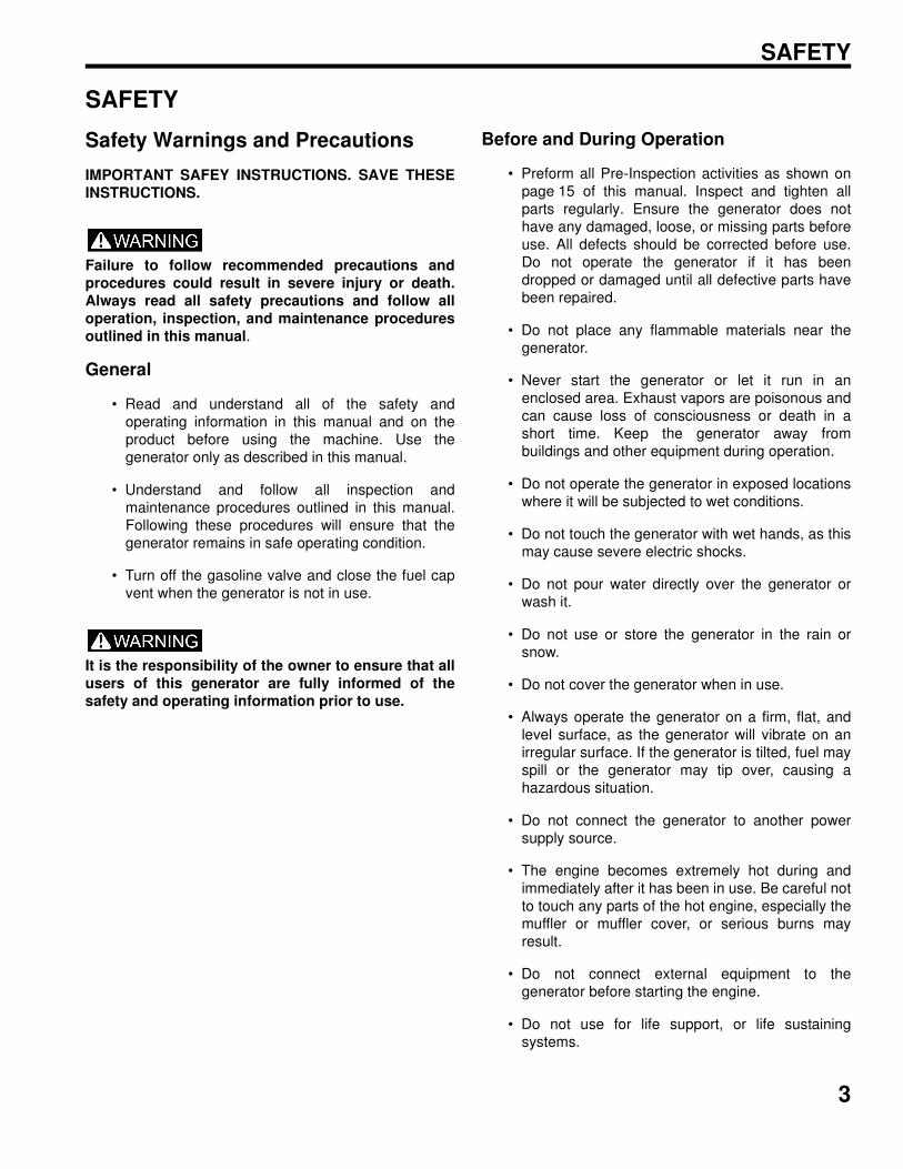
Failure to follow recommended precautions and
procedures could result in severe injury or death.
Always read all safety precautions and follow all
operation, inspection, and maintenance procedures
outlined in this manual.
General
• Read and understand all of the safety and
operating information in this manual and on the
product before using the machine. Use the
generator only as described in this manual.
• Understand and follow all inspection and
maintenance procedures outlined in this manual.
Following these procedures will ensure that the
generator remains in safe operating condition.
• Turn off the gasoline valve and close the fuel cap
vent when the generator is not in use.
It is the responsibility of the owner to ensure that all
users of this generator are fully informed of the
safety and operating information prior to use.
Before and During Operation
• Preform all Pre-Inspection activities as shown on
page 15 of this manual. Inspect and tighten all
parts regularly. Ensure the generator does not
have any damaged, loose, or missing parts before
use. All defects should be corrected before use.
Do not operate the generator if it has been
dropped or damaged until all defective parts have
been repaired.
• Do not place any flammable materials near the
generator.
• Never start the generator or let it run in an
enclosed area. Exhaust vapors are poisonous and
can cause loss of consciousness or death in a
short time. Keep the generator away from
buildings and other equipment during operation.
• Do not operate the generator in exposed locations
where it will be subjected to wet conditions.
• Do not touch the generator with wet hands, as this
may cause severe electric shocks.
• Do not pour water directly over the generator or
wash it.
• Do not use or store the generator in the rain or
snow.
• Do not cover the generator when in use.
• Always operate the generator on a firm, flat, and
level surface, as the generator will vibrate on an
irregular surface. If the generator is tilted, fuel may
spill or the generator may tip over, causing a
hazardous situation.
• Do not connect the generator to another power
supply source.
• The engine becomes extremely hot during and
immediately after it has been in use. Be careful not
to touch any parts of the hot engine, especially the
muffler or muffler cover, or serious burns may
result.
• Do not connect external equipment to the
generator before starting the engine.
• Do not use for life support, or life sustaining
systems.
4
SAFETY
Operator Safety
Operating the generator with worn, damaged, or
malfunctioning components could result in serious
injury or death. Never start the engine without
checking all of the generator components to be sure
of proper operation.
• Read and understand all of the safety and
operating information in this manual and on all
warning labels before using the generator. Use the
generator only as described in this manual.
• Know how to stop the generator quickly in case of
emergency, see page 19 for information on
stopping the unit quickly.
• Keep children, pets, and bystanders at a safe
distance from the generator.
• Review and understand the use of all generator
controls.
• Be sure that anyone who operates the generator
receives proper instruction. Do not let children
operate the generator.
• Use the generator only for intended purposes.
• Turn off the generator immediately if the unit
begins to operate abnormally. After the generator
has cooled, disconnect the generator and take to
your authorized Polaris dealer.
• While operating the generator, if you experience
headache, fatigue, nausea / vomiting, confusion,
or seizures, immediately get to fresh air. Do not
delay and do not attempt to shut down the unit.
Fuel Safety
Gasoline is highly flammable and explosive under
certain conditions. Always use caution when
handling gasoline.
• Gasoline is extremely flammable, and gasoline
vapor can explode. Before refueling allow the
engine to cool completely if the generator has
been in operation.
• Always store gasoline in an approved container.
• Always refuel outdoors or in a well-ventilated area
away from any combustible materials.
• Do not smoke or allow open flames or sparks in or
near the area where refueling is performed or
where gasoline is stored.
• Never permit children to handle gasoline.
• Never refuel around bystanders, pets, and
flammable objects.
• Loosen the fuel cap slowly to relieve pressure in
the tank.
• Take care not to overfull or spill any fuel on the
generator or muffler when refueling.
• If gasoline spills on skin or clothing, immediately
wash it off with soap and water and change
clothing.
• Do not use the generator if you observe leaking
gasoline. Have the generator serviced
immediately and before using it again.
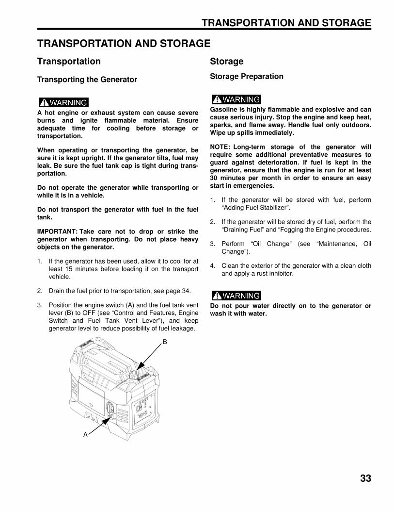
• When operating or transporting the generator, be
sure it is kept upright. If it tilts, fuel may leak. Be
sure the fuel tank cap is tightened when
transporting the generator.
• Do not refuel using gas station pumps.
• Remove fuel from the generator before
transporting in a vehicle.
Do not swallow gasoline, inhale gasoline vapors, or
spill gasoline. If you swallow gasoline, inhale more
than a few breaths of gasoline vapor, or splash
gasoline in your eyes, see a physician immediately. If
gasoline spills on skin or clothing, immediately wash
it off with soap and water and change clothing.
5
SAFETY
Carbon Monoxide Safety
Generator exhaust contains Carbon Monoxide (CO)
vapors. Exposure to Carbon Monoxide by people or
pets can result in SEVERE INURY or DEATH.
ALWAYS operate generate according to guidelines in
labels and this manual.
• This portable generator runs on gasoline. The
generator exhaust vapor contains carbon
monoxide (CO).
• Carbon monoxide is odorless. You cannot smell it.
• Carbon monoxide is colorless. You cannot see it.
• Never run an engine in an enclosed area. Exhaust
contains poisonous carbon monoxide vapor that
can cause loss of consciousness or death.
Operate the engine in an open area, and well
ventilated. The generator is for outdoor use only.
• Do not use the generator indoors in garages,
basements, crawl spaces, sheds, portable
buildings, or similar areas even if doors and / or
windows are open or if ventilating fans are used to
circulate air.
• Do not use the generator near windows, doors,
vents or any other building openings even if they
are closed. Poor seals on a door, as just one
example, could still permit high levels of carbon
monoxide to infiltrate the living area of a home.
• Be sure to install approved carbon monoxide
detectors in your home that have battery back-up
systems that will continue to detect the presence
of carbon monoxide during electric-power outages.
Test these devices and replace batteries as
recommended by their respective manufacturers.
• If you experience headache, fatigue, nausea /
vomiting, confusion, or seizures, immediately get
to fresh air and away from the unit. Do not delay
for any reason.
Electrical Safety
This generator produces high voltage electricity.
• The generator produces enough electric power to
cause serious shock or electrocution if misused.
• Always connect the generator to a suitable ground
circuit.
• When servicing the generator, disconnect the
spark plug wire and place it where it cannot
contact the plug. Turn the engine switch to the
OFF position.
• Do not check for a spark with the plug removed.
Use only approved spark plug testers.
• Using a generator or electrical appliance in wet
conditions, such as rain or snow, or near a pool or
sprinkler system, or when your hands are wet,
could result in electrocution. Keep the generator
dry and away from all sources of moisture.
• Do not store the generator outdoors unprotected
from the weather.
• If the Generator has been subjected to water,
moisture, or ice check all of the electrical
components on the control panel before each use.
Moisture or ice can cause a malfunction or short
circuit in electrical components that could result in
electrocution.
• Do not connect the generator to a building’s
electrical system unless an isolation switch has
been installed that meets applicable electrical
codes and regulations.
• To avoid overloading the generator, ensure that
the load is kept within the rating stated on the
generator. Overloading will damage the unit and /
or shorten its operating lifespan.
• P1000i or P2000i can be paralleled with another
P1000i or P2000i using the Polaris parallel kits.
• Do not over charge a battery with the DC
receptacle, over charging the battery may result in
battery damage and potential ignite if a spark is
introduced.
6
SAFETY
Fire Safety
Generator exhaust system gets hot enough to ignite
some materials and burn skin if touched.
• Keep the generator away from buildings, other
equipment, and combustible materials during
operation.
• Do not enclose the generator in any structure.
• Keep children and pets away from generator.
• Exhaust system components are very hot during
and after use. Hot components can cause burns
and fire. Do not touch the hot exhaust system
components. Always keep combustible materials
away from the exhaust system.
• Ensure that any spilled fuel is properly wiped up
prior to using the generator as fuel vapors are
flammable.
Extension Cord Information
• Read the manufacturer starting and running
wattage details and operating instructions for the
device(s) and appliance(s) that will be used. Often
this information can be found in the owner's
manual or on specification decals on the device or
appliance.
• Polaris recommends using only U.L. (Underwriters
Laboratories, Inc.) approved extension cords
labeled with the use, size, and wattage rating.
Only use heavy-duty extension cords with a three-
prong (grounded) plug for your safety. Decide on
what length extension cord is required as cord
length determines the extension cord gauge.
Remember, as the cord gets longer, the current
capacity of the cord decreases.
• Never use an extension cord designated as
“indoor use only” outdoors.
• Store all extension cords indoors when not in use.
Outdoor conditions can deteriorate a cord over
time.
• Never keep an extension cord plugged in when not
in use. The cord will still conduct electricity until it
is unplugged from the outlet.
• Before plugging an extension cord or power cord
into the generator, check the cord for any signs of
damage.
Equipment Modifications
Modifying the generator by adding or removing any
equipment not approved by Polaris may void the
warranty. Such modifications may make the generator
unsafe to operate and could result in severe injury to
operators and / or bystanders, as well as damage to the
generator. Some modifications may not be legal in your
area. If in doubt, contact your authorized Polaris dealer.
7
SAFETY
Safety Labels and Locations
Safety and warning decals have been placed on the
generator for your protection. Read and follow the
instructions of the decals and warnings on the generator
carefully. If any of the decals depicted in this manual differ
from the decals on your generator, always read and
follow the instructions of the decals on the generator.
Carbon Monoxide Warning
Using a generator indoors CAN KILL YOU IN
MINUTES.
The carbon monoxide warning is located on top of the
generator.
Outdoor Use ONLY Danger Label
Generator Exhaust contains carbon monoxide. This
is a poison you cannot see or smell.
NEVER use inside a home or garage, EVEN IF doors
and windows are open.
Only use OUTSIDE and far away from windows,
doors, and vents.
Hot Exhaust Caution
The hot exhaust caution is located on the muffler
cover.
Contacting a hot exhaust system can cause serious
burns.
Do not touch if generator is or has been running.
Improper Generator use can result in SEVERE
INJURY or DEATH. Read the OWNER’S MANUAL.
Follow all Instructions and Warnings.
Gasoline is flammable and explosive. Severe burns
can result. ALWAYS stop the engine and let cool
down before refueling. ALWAYS check for fuel leaks
and wipe up any spills. ALWAYS turn the fuel to OFF
when not in use. NEVER handle gasoline indoors.
NEVER overfill the fuel tank.
Generator exhaust contains poisonous Carbon
Monoxide (CO) vapors. ALWAYS operate in a well-
ventilated area. NEVER operate in a home, garage,
enclosed area or near windows, doors, or people.
NEVER operate near flammable objects.
Electrocution can result from using generator in rain,
snow, near water, with wet hands, or with improper
connections. ALWAYS keep generator and
surrounding area dry. NEVER connect generator to
any building without electrical-isolation protection
that meets applicable codes and regulations.
WARNINGImproper Generator use can result in SEVERE INJURY or DEATH. Read the Owner’s Manual. Follow all instructions and Warnings.
Generator exhaust contains poisonous
Carbon Monoxide (CO) vapors. ALWAYS
operate in a well-ventilated area.
NEVER operate in a home, garage, enclosed
area or near windows, doors, or people.
NEVER operate near "ammable objects.
Gasoline is "ammable and explosive. Severe
burns can result. ALWAYS stop engine and let
cool before refueling. ALWAYS check for fuel
leaks and wipe up any spills. ALWAYS turn fuel to
OFF when not in use. NEVER handle gasoline
indoors. NEVER over#ll fuel tank.
Electrocution can result from using generator in rain,
snow, near water, with wet hands, or with improper
connections. ALWAYS keep generator and surrounding
area dry. NEVER connect generator to any building
without electrical-isolation protection that meets
applicable codes and regulations.
DANGERUsing a generator indoors CAN KILL YOU IN MINUTES.
Generator exhaust contains carbon monoxide.
This is a poison you cannot see or smell.
NEVER use inside a home
or garage. EVEN IF doors
and windows are open.
Only use OUTSIDE and
far away from windows,
doors, and vents.
CAUTION
Contacting a hot exhaust system can cause serious burns.Do not touch if generator is or has been running.
NOTES
SAFETY
8
9
CONTROLS AND FEATURES
CONTROLS AND FEATURES
Generator Components:
B
A
C
D
EF
H
I
JG
ITEM NOMENCLATURE DESCRIPTION
A Spark Plug Cap Remove the top to access the spark plug
B Control Panel Generator controls
C Air Filter Protects the air flow to the carburetor from becoming obstructed with debris
D Oil Dipstick Measures oil level in the engine
E Carburetor Vent Hose Atmospheric vent
F Carburetor Drain Hose Drains fuel from the carburetor
G Starter Recoil Grip Causes the recoil starter to crank the engine when pulled
H Choke Lever Provides proper starting mixture when engine is cold
I Fuel Tank Cap Accesses fuel tank
J Engine / Fuel Switch Controls the ignition system and the fuel valve
10
CONTROLS AND FEATURES
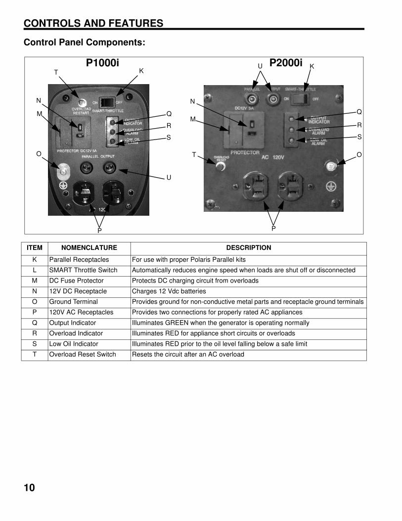
Control Panel Components:
ITEM NOMENCLATURE DESCRIPTION
K Parallel Receptacles For use with proper Polaris Parallel kits
L SMART Throttle Switch Automatically reduces engine speed when loads are shut off or disconnected
M DC Fuse Protector Protects DC charging circuit from overloads
N 12V DC Receptacle Charges 12 Vdc batteries
O Ground Terminal Provides ground for non-conductive metal parts and receptacle ground terminals
P 120V AC Receptacles Provides two connections for properly rated AC appliances
Q Output Indicator Illuminates GREEN when the generator is operating normally
R Overload Indicator Illuminates RED for appliance short circuits or overloads
S Low Oil Indicator Illuminates RED prior to the oil level falling below a safe limit
T Overload Reset Switch Resets the circuit after an AC overload
K
M
N
O
P
Q
R
S
T
UK
M
N
P
Q
R
S
T
U
O
P1000i P2000i
11
CONTROLS AND FEATURES
Controls and Features
Choke Lever
Move the choke lever (H) to the START position when
starting a cold engine. Slowly move the choke lever to the
RUN position as the engine RPM stabilizes.
Fuel Tank Cap Vent Lever (if equipped)
When the engine is well-cooled and not in use, the fuel
tank cap vent lever (I) must be placed in the OFF position
to reduce the possibility of fuel leakage. The vent lever
must be in the ON position to allow the engine to operate.
Engine Fuel Switch
The engine switch (J) controls the ignition system and the
fuel valve. ON: opens the fuel valve and allows the engine
to be started. OFF: closes the fuel valve and shuts off the
engine.
Starter Recoil Grip
Do not allow starter grip to snap back against the
generator. Return it gently to prevent damage to the
starter.
The starter recoil grip (G) causes the recoil starter to
crank the engine when pulled.
SMART Throttle Switch
The SMART throttle switch (L) automatically reduces
engine speed when loads are shut off or disconnected.
The engine returns to the proper speed to power the
electrical load when appliances are turned ON or
reconnected. Press the SMART throttle switch to the OFF
position to reduce voltage changes when high electrical
loads are simultaneously connected or when using the
DC output.
DC Receptacle and Fuse
The DC receptacle (N) is protected from an overload with
a fuse. If the DC circuit is overloaded, the 5 amp fuse (M)
will blow and power to the DC receptacle will cease. The
red light on the DC panel will illuminate. The fuse is
located to the left of the receptacle and is accessed by
snapping open the access door. Replace the fuse with
one of the same capacity. Using a higher rated fuse may
cause damage to the generator alternator.
The DC receptacle charges 12 Vdc automotive-type bat-
teries. The DC charging output is not regulated.
OFF
ON
ON
OFF
ON
OFF
OFFON
M N
12
CONTROLS AND FEATURES
Ground Terminal
The ground terminal (O) connects to the frame of the
generator, metal parts that do not conduct current, and
ground terminals of each receptacle. Consult a qualified
electrician, electrical inspector, or local agency having
jurisdiction for local codes or ordinances for the intended
use of the generator before using the ground terminal.
AC Receptacles
The AC receptacles (P) provide two connections for
properly rated AC appliances, see page 38 for
specifications. .
Indicator Panel
Output Indicator
The output indicator (Q) illuminates GREEN when the
generator is in normal operation and producing electrical
power at the receptacles.
Overload Indicator
The overload indicator (R) illuminates RED if there is a
short circuit in the connected appliance(s), or if the
generator is overloaded. The light remains illuminated for
5 seconds, then the current to the connected appliance is
shut off and the output indicator light (GREEN)
extinguishes.
Low Oil Indicator
The low oil indicator (S) illuminates RED before the oil
level falls below a safe limit and the detection system
automatically stops the engine. When there is a low
engine oil level at startup, the engine will be prevented
from starting.
Overload Protector Reset Switch
Should the generator overload, AC power will be cut off
but the engine will stay running. Correct the overload
condition and then press the overload reset switch (T)on
the front panel. AC power will be restored immediately.
Parallel Receptacles
Two Polaris parallel ready generators can be connected
together to increase the total power available to a load,
using the parallel receptacles (K). The system seamlessly
matches frequency and automatically evenly distributes
the load to each generator so one is not overloaded.
Contact your dealer for the proper kit for your particular
application.
Q
R
S
13
FIRST USE INSTRUCTIONS
FIRST USE INSTRUCTIONS
Adding Engine Oil
Failure to use the recommended 4-stroke engine oil may
result in engine damage, see page 38 for recommended
oil and capacity.
1. Place generator on flat, level surface. Remove the
maintenance cover (see “Maintenance, Removing
the Maintenance Cover”).
2. Remove the oil filler cap / dipstick (A).
3. Fill the engine crankcase with the specified amount
(see Specifications section) of engine oil.
4. Insert the dipstick into the filler neck, without screwing
it in.
5. Remove the dipstick and verify that the oil level is at
the upper limit (B). Add additional oil and inspect the
level as needed until the upper limit has been
reached.
6. Re-install the dipstick (A). Use a clean shop rag to
clean any spilled oil.
7. Re-install the maintenance cover.
A
Upper Level
B
14
FIRST USE INSTRUCTIONS
Fuel RecommendationPolaris recommends the use of 87 octane fuel or higher.
Do not use fuel containing more than 10% ethanol. Do
not use gasoline containing methanol.
IMPORTANT: Operating the generator with anobstructed fuel system will result in serious enginedamage. Perform maintenance as recommended.
IMPORTANT: Thoroughly read “Safety” section andall safety information when handling fuel.
IMPORTANT: In order to insure the optimum outputand the maximum service life of the generator, thegenerator should run at a 50% load for the first 20hours
Gasoline is highly flammable and explosive and can
cause serious injury. Stop the engine and keep heat,
sparks, and flame away. Handle fuel only outdoors.
Wipe up spills immediately.
Do not spill fuel when filling the fuel tank. Damage
caused by spilled fuel is not covered under warranty.
Spilled fuel is a fire hazard, causes environmental
damage, and can damage paint and plastic. Wipe up
spills immediately. Don fill above bottom of strainer.
Refuel in a well ventilated area before starting the en-
gine. If the engine has been running, allow it to cool.
Never refuel the engine inside a building where va-
pors may reach flames or sparks. Keep fuel vapors
away from electrical appliances.
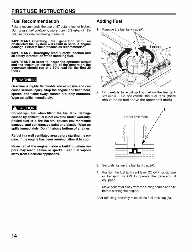
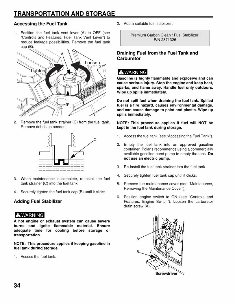
Adding Fuel
1. Remove the fuel tank cap (A).
2. Fill carefully to avoid spilling fuel on the fuel tank
strainer (B). Do not overfill the fuel tank (thereshould be no fuel above the upper limit mark) .
3. Securely tighten the fuel tank cap (A).
4. Position the fuel tank vent lever (C) OFF for storage
or transport, or ON to operate the generator, if
equipped.
5. Move generator away from the fueling source and site
before starting the engine.
After refueling, securely reinstall the fuel tank cap (A).
Loosen
Tighten
C
A
B
15
PRE-OPERATION INSPECTION
PRE-OPERATION INSPECTION
NOTE: Always perform the recommended pre-
operation inspections before each use. Always
perform the inspections at the beginning of a project
and when removing the generator from storage.
Failure to perform the recommended pre-operation
inspections could result in minor or moderate injury
or property damage. When inspection reveals the
need for adjustment, replacement, or repair, perform
service promptly.
Pre-Operation Checklist
Remove the maintenance cover (see “Maintenance,
Removing the Maintenance Cover”) to expose the
generator inner components.
Engine Oil
Perform “Oil Level Inspection” (see “Maintenance,
Engine Oil”). Add oil as needed.
Fuel Line
Gasoline is highly flammable and explosive and can
cause serious injury. Stop the engine and keep heat,
sparks, and flame away. Handle fuel only outdoors.
Wipe up spills immediately.
Inspect the fuel hose for cracks or damage. Replace as
needed.
Fuel Level
Check the fuel level and refuel as needed (see
“Operation, Refueling”).
Exhaust System
If the engine has been running, the muffler will be
very hot. Allow the muffler to cool before servicing.
Inspect the exhaust system for leakage. Tighten or re-
place the gasket as needed.
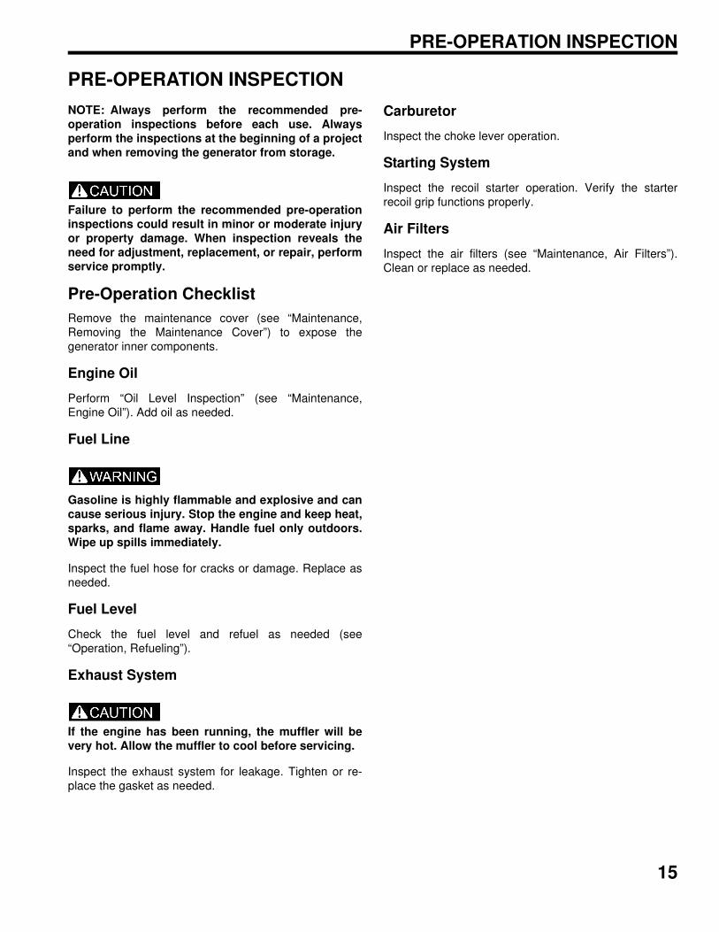
Carburetor
Inspect the choke lever operation.
Starting System
Inspect the recoil starter operation. Verify the starter
recoil grip functions properly.
Air Filters
Inspect the air filters (see “Maintenance, Air Filters”).
Clean or replace as needed.
NOTES
PRE-OPERATION INSPECTION
16
17
OPERATION
Safe Operating Precautions
Fuel Recommendations
The generator engine is certified to operate on regular
unleaded gasoline with a pump octane rating of 87 or
higher.
Never use stale or contaminated gasoline or an oil /
gasoline mixture. Avoid getting dirt or water in the fuel
tank.
The use of regular unleaded gasoline containing no more
than 10% ethanol (E10) by volume is permitted. Do not
use gasoline containing methanol. If the content of
ethanol or methanol exceeds the specified limits, it may
cause starting or performance problems. It may also
damage metal, rubber, and plastic parts of the fuel
system. Damage due to ethanol or methanol is not
covered under warranty.
Refueling
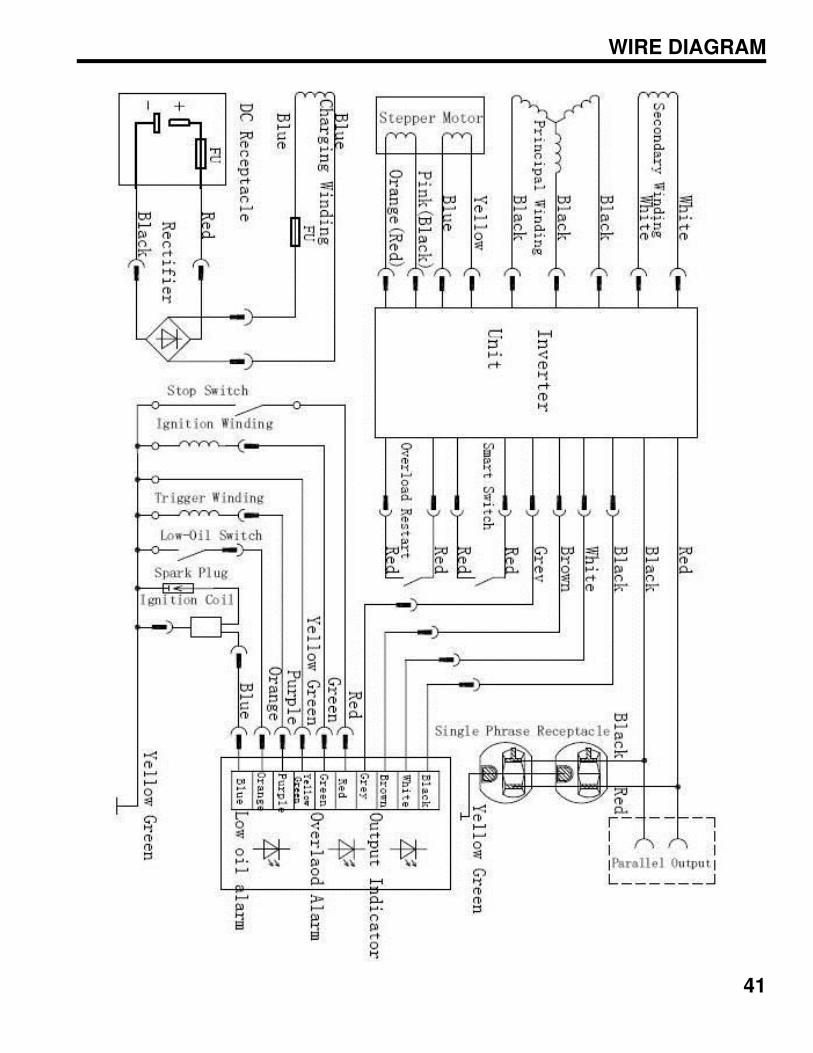
IMPORTANT: Thoroughly read the “Safety” chapterand all warnings and cautions when handling fuel.
Gasoline is highly flammable and explosive and can
cause serious injury. Stop the engine and keep heat,
sparks, and flame away. Handle fuel only outdoors.
Wipe up spills immediately.
Do not spill fuel when filling the fuel tank. Damage
caused by spilled fuel is not covered under warranty.
Spilled fuel is a fire hazard, caused environmental
damage, and can damage paint and plastic. Wipe up
spills immediately. Don fill above bottom of strainer.
Refuel in a well ventilated area before starting the en-
gine. If the engine has been running, allow it to cool.
Never refuel the engine inside a building where
vapors may reach flames or sparks. Keep fuel vapors
away from electrical appliances.
1. Remove the fuel tank cap (A).
2. Fill carefully to avoid spilling fuel or exceeding the
bottom of the fuel tank strainer (B).
3. Securely tighten the fuel tank cap (A) until it clicks.
4. Position the fuel tank vent lever OFF for storage or
transport, or ON to operate the generator, if equipped.
5. Move generator at least 10 feet (3 meters) away from
the fueling source and site before starting the engine.
Loosen
Tighten
A
B
ON
OFF
18
OPERATION
Before Starting the Engine
Read, understand, and follow the Safety Section of this
manual.
1. Ensure the generator is away from the fueling source.
2. The generator will vibrate during operation. Place the
generator in a dry location and on a flat, level surface.
3. Unplug all power cords and extension cords from the
generator.
Starting the Engine
1. Position the fuel tank cap vent lever to ON, if
equipped.
2. Position the SMART throttle switch to OFF.
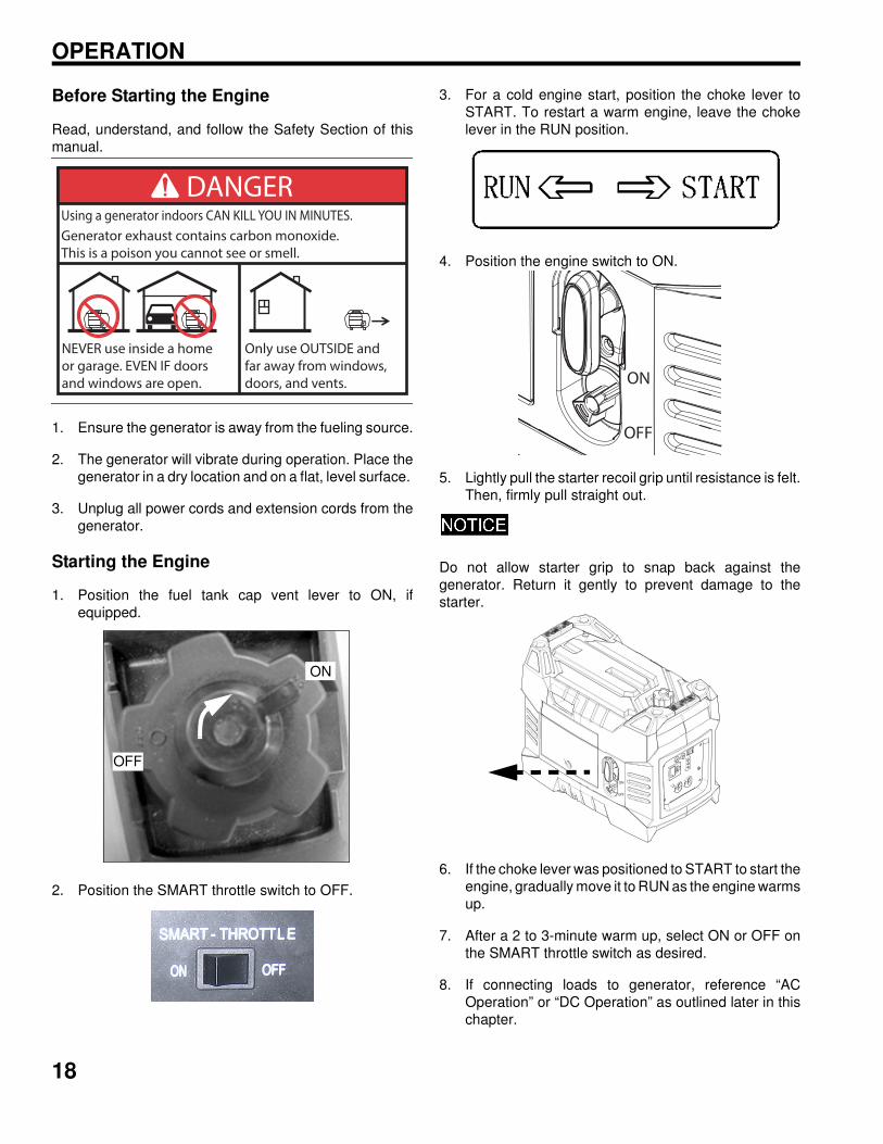
3. For a cold engine start, position the choke lever to
START. To restart a warm engine, leave the choke
lever in the RUN position.
4. Position the engine switch to ON.
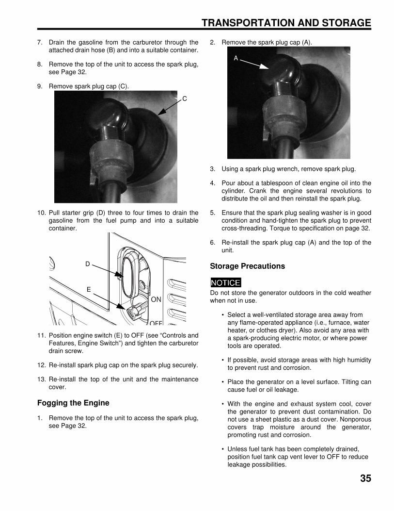
5. Lightly pull the starter recoil grip until resistance is felt.
Then, firmly pull straight out.
Do not allow starter grip to snap back against the
generator. Return it gently to prevent damage to the
starter.
6. If the choke lever was positioned to START to start the
engine, gradually move it to RUN as the engine warms
up.
7. After a 2 to 3-minute warm up, select ON or OFF on
the SMART throttle switch as desired.
8. If connecting loads to generator, reference “AC
Operation” or “DC Operation” as outlined later in this
chapter.
DANGERUsing a generator indoors CAN KILL YOU IN MINUTES.
Generator exhaust contains carbon monoxide.
This is a poison you cannot see or smell.
NEVER use inside a home
or garage. EVEN IF doors
and windows are open.
Only use OUTSIDE and
far away from windows,
doors, and vents.
OFF
ON
ON
OFF
ON
OFF
19
OPERATION
Stopping the Engine
In case of emergency, position the engine switch to OFF
to stop the engine. Under normal conditions, perform the
following procedure.
1. Shut off or disconnect all appliances connected to the
generator.
2. Position the engine switch to OFF.
3. Allow the engine to cool and position the fuel tank cap
vent lever to OFF.
AC Operation
Before connecting a device or power cord to the
generator, ensure it is in good condition. Faulty
appliances or power cords can create a potential for
electrical shock.
If an appliance begins to operate abnormally,
becomes sluggish, or suddenly stops, immediately
shut it off. Disconnect the appliance and determine
whether the problem is the appliance or if the rated
load capacity of the generator has been exceeded.
Ensure the combined electrical rating of the device or
appliance does not exceed the maximum allowed by
the generator. Never exceed the maximum power
rating of the generator. Power levels between rated
and maximum may be used for no more than 30
minutes.
NOTE: When the electric motor starts, the overload
indicator (middle light) may illuminate (RED) and
extinguish within 4 seconds. If the overload
indicator remains illuminated, consult the generator
dealer.
NOTE: In order to insure the optimum output and
the maximum service life of the generator, the
generator should run at a 50% load for the first 20
hours
1. Start the engine and ensure that the output indicator
(A) illuminates (GREEN).
2. Plug the device or extension cord into one of the AC
receptacles (B).
ON
OFF
OFF
ON
A
B
20
OPERATION
3. Turn on the device.
NOTE: If the generator is overloaded or if there is a
short circuit in a connected appliance, the overload
indicator (RED) will illuminate. The overload
indicator will remain illuminated and, after about 4
seconds, current to the connected appliance(s) will
shut off but the engine will stay running. The output
indicator (GREEN) will extinguish.
4. If overloaded or short circuit in a connected device
occurs, stop the engine and refer to the
“Troubleshooting” chapter. Determine if the cause is
a short circuit in the connected device or an overload.
Correct the problem and restart the generator.
5. After determining the cause of the overload and when
it is safe to resume using the AC power in order to
correct the overload condition and then press the
overload reset switch on the front panel. AC power will
be restored immediately.
AC Capacity
In case of substantial overloading, the electronic circuit
protector will activate. Slightly overloading the generator
or running at maximum power operation (30 minutes)
may not switch the circuit ON, but will shorten the service
life of the generator.
Maximum power is:
(see “Specifications” page)
For continuous operation, do not exceed rated power:
(see “Specifications” page)
Consider the total power requirements of all connected
devices. Appliance and power-tool manufacturers usually
list the rating information near the model or serial number.
After plugging in a device, allow the generator to stabilize
before plugging in additional items. Always consider the
generator capacity before plugging in any device.
NOTE: Typical wattages are listed in the table below.
Before plugging any device into the generator, verify
the manufacturer-listed wattage on the device.
Wattage Reference Table
DEVICE
RUNNING
(RATED)
WATTS
ADDITIONAL
STARTING
(SURGE)
WATTS
Circular Saw - 7 1/4” 1400 2300
Coffee Maker 1000 0
Dehumidifier 650 800
Electric Drill -
3/8”, 4 Amps440 600
Hair Dryer 300 - 1200 0
Light Bulb (75-Watt) 75 0
Microwave Oven
1000-Watt1000 1400
Paint Sprayer 360 1080
Heat Pump 4700 4500
Personal Computer
with 17” Monitor800 0
Radio 300 300
Refrigerator 400 - 800 2200
Space / Wall Heater 1800 0
Table Saw / Radial Arm
Saw - 10”2000 2000
Do not use or only use with the Polaris Parallel Kit,
see page 23 for more information
High-Pressure Washer-
1 HP1200 3600
Garage Door Opener
1/2 HP875 2350
Sump Pump - 1/2 HP 1050 2200
Central AC Unit
48,000 BTU6000 7800
Television (Color) - 27” 500 0
Air Compressor - 1 HP 1600 4500
21
OPERATION
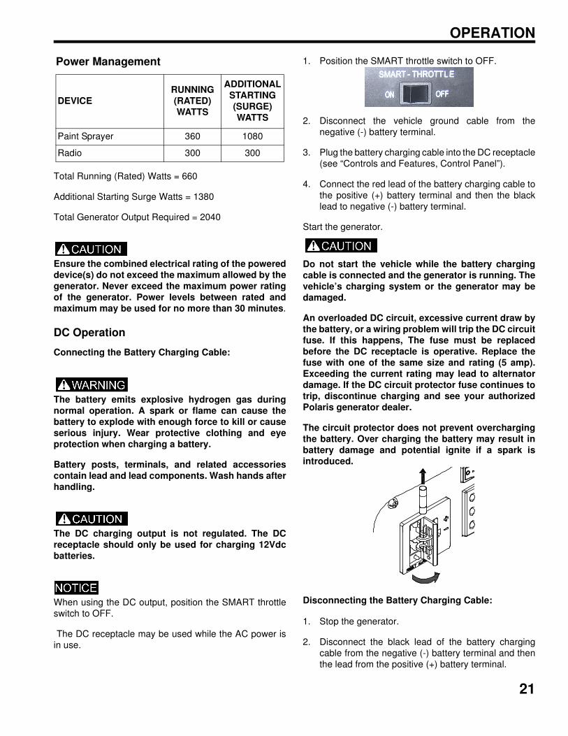
Total Running (Rated) Watts = 660
Additional Starting Surge Watts = 1380
Total Generator Output Required = 2040
Ensure the combined electrical rating of the powered
device(s) do not exceed the maximum allowed by the
generator. Never exceed the maximum power rating
of the generator. Power levels between rated and
maximum may be used for no more than 30 minutes.
DC Operation
Connecting the Battery Charging Cable:
The battery emits explosive hydrogen gas during
normal operation. A spark or flame can cause the
battery to explode with enough force to kill or cause
serious injury. Wear protective clothing and eye
protection when charging a battery.
Battery posts, terminals, and related accessories
contain lead and lead components. Wash hands after
handling.
The DC charging output is not regulated. The DC
receptacle should only be used for charging 12Vdc
batteries.
When using the DC output, position the SMART throttle
switch to OFF.
The DC receptacle may be used while the AC power is
in use.
1. Position the SMART throttle switch to OFF.
2. Disconnect the vehicle ground cable from the
negative (-) battery terminal.
3. Plug the battery charging cable into the DC receptacle
(see “Controls and Features, Control Panel”).
4. Connect the red lead of the battery charging cable to
the positive (+) battery terminal and then the black
lead to negative (-) battery terminal.
Start the generator.
Do not start the vehicle while the battery charging
cable is connected and the generator is running. The
vehicle’s charging system or the generator may be
damaged.
An overloaded DC circuit, excessive current draw by
the battery, or a wiring problem will trip the DC circuit
fuse. If this happens, The fuse must be replaced
before the DC receptacle is operative. Replace the
fuse with one of the same size and rating (5 amp).
Exceeding the current rating may lead to alternator
damage. If the DC circuit protector fuse continues to
trip, discontinue charging and see your authorized
Polaris generator dealer.
The circuit protector does not prevent overcharging
the battery. Over charging the battery may result in
battery damage and potential ignite if a spark is
introduced.
Disconnecting the Battery Charging Cable:
1. Stop the generator.
2. Disconnect the black lead of the battery charging
cable from the negative (-) battery terminal and then
the lead from the positive (+) battery terminal.
Power Management
DEVICE
RUNNING
(RATED)
WATTS
ADDITIONAL
STARTING
(SURGE)
WATTS
Paint Sprayer 360 1080
Radio 300 300
22
OPERATION
3. Unplug the battery charging cable from the DC
receptacle (see “Controls and Features, Control
Panel”).
4. Connect the vehicle battery ground cable to the
negative (-) battery terminal.
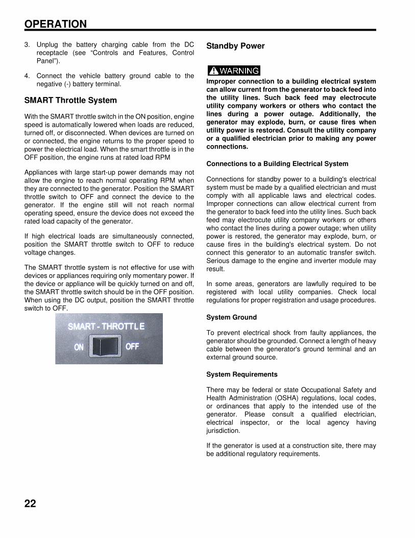
SMART Throttle System
With the SMART throttle switch in the ON position, engine
speed is automatically lowered when loads are reduced,
turned off, or disconnected. When devices are turned on
or connected, the engine returns to the proper speed to
power the electrical load. When the smart throttle is in the
OFF position, the engine runs at rated load RPM
Appliances with large start-up power demands may not
allow the engine to reach normal operating RPM when
they are connected to the generator. Position the SMART
throttle switch to OFF and connect the device to the
generator. If the engine still will not reach normal
operating speed, ensure the device does not exceed the
rated load capacity of the generator.
If high electrical loads are simultaneously connected,
position the SMART throttle switch to OFF to reduce
voltage changes.
The SMART throttle system is not effective for use with
devices or appliances requiring only momentary power. If
the device or appliance will be quickly turned on and off,
the SMART throttle switch should be in the OFF position.
When using the DC output, position the SMART throttle
switch to OFF.
Standby Power
Improper connection to a building electrical system
can allow current from the generator to back feed into
the utility lines. Such back feed may electrocute
utility company workers or others who contact the
lines during a power outage. Additionally, the
generator may explode, burn, or cause fires when
utility power is restored. Consult the utility company
or a qualified electrician prior to making any power
connections.
Connections to a Building Electrical System
Connections for standby power to a building's electrical
system must be made by a qualified electrician and must
comply with all applicable laws and electrical codes.
Improper connections can allow electrical current from
the generator to back feed into the utility lines. Such back
feed may electrocute utility company workers or others
who contact the lines during a power outage; when utility
power is restored, the generator may explode, burn, or
cause fires in the building's electrical system. Do not
connect this generator to an automatic transfer switch.
Serious damage to the engine and inverter module may
result.
In some areas, generators are lawfully required to be
registered with local utility companies. Check local
regulations for proper registration and usage procedures.
System Ground
To prevent electrical shock from faulty appliances, the
generator should be grounded. Connect a length of heavy
cable between the generator's ground terminal and an
external ground source.
System Requirements
There may be federal or state Occupational Safety and
Health Administration (OSHA) regulations, local codes,
or ordinances that apply to the intended use of the
generator. Please consult a qualified electrician,
electrical inspector, or the local agency having
jurisdiction.
If the generator is used at a construction site, there may
be additional regulatory requirements.
23
OPERATION
PARALLEL GENERATOR OPERATION
Parallel operation features, kits sold separately.
Two Polaris parallel ready generators can be connected
together to increase the total power available to a load.
The system seamlessly matches frequency and
automatically evenly distributes the load to each
generator so one is not overloaded.
Operating the generators in parallel has 0.9 power de-
rate factor. For example, connecting a 1kw and 2kw
together in parallel operation, the continuous rated
combined output will equal 0.9x (900w + 1600w) =
2250W.
Any combination of two Polaris parallel ready generators
can be connected such as a P2000i and a P1000i, two
P2000i models, etc. There are two different parallel
connection kits. One kit has a 30A receptacle ideal for
connecting two P2000i models or a P2000i and a P1000i.
Parallel operation procedure.
1 Turn off both generators and disconnect all the
electrical devices from the generators
2. Prepare two parallel ready generators for operation.
Place them on a hard and level surface.
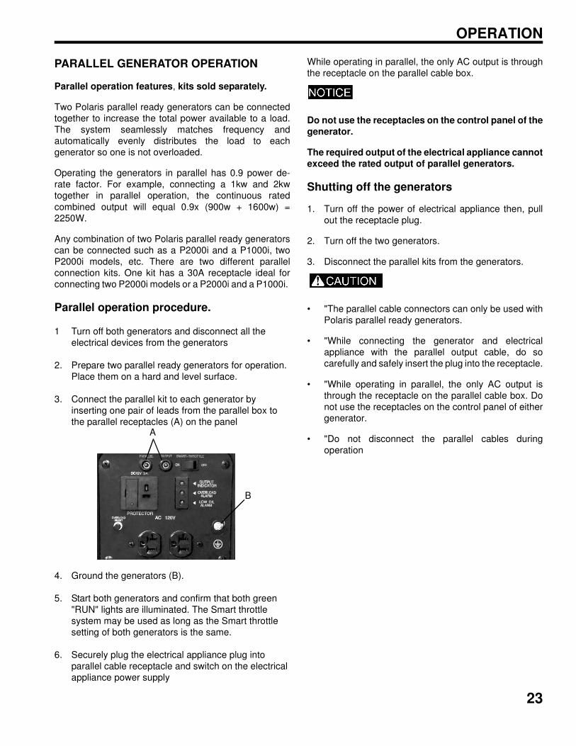
3. Connect the parallel kit to each generator by
inserting one pair of leads from the parallel box to
the parallel receptacles (A) on the panel
4. Ground the generators (B).
5. Start both generators and confirm that both green
"RUN" lights are illuminated. The Smart throttle
system may be used as long as the Smart throttle
setting of both generators is the same.
6. Securely plug the electrical appliance plug into
parallel cable receptacle and switch on the electrical
appliance power supply
While operating in parallel, the only AC output is through
the receptacle on the parallel cable box.
Do not use the receptacles on the control panel of the
generator.
The required output of the electrical appliance cannot
exceed the rated output of parallel generators.
Shutting off the generators
1. Turn off the power of electrical appliance then, pull
out the receptacle plug.
2. Turn off the two generators.
3. Disconnect the parallel kits from the generators.
• "The parallel cable connectors can only be used with
Polaris parallel ready generators.
• "While connecting the generator and electrical
appliance with the parallel output cable, do so
carefully and safely insert the plug into the receptacle.
• "While operating in parallel, the only AC output is
through the receptacle on the parallel cable box. Do
not use the receptacles on the control panel of either
generator.
• "Do not disconnect the parallel cables during
operation
A
B
24
OPERATION
High Altitude Use
Carburetor Modification
When carburetor has been modified for high altitude
operation, the air-fuel mixture will be too lean for low
altitude use and may cause engine damage.
At high altitude, the standard carburetor air-fuel mixture
will be excessively rich. Performance will decrease and
fuel consumption will increase. A very rich mixture will
also foul the spark plug and cause hard starting.
Operation at an altitude different than that which this
engine was certified, for extended periods of time, may
increase emissions.
High altitude operation can be improved by specific
modifications to the carburetor. If always operating the
generator at altitudes above 5000 feet (1500 meters),
have an authorized Polaris servicing dealer perform the
carburetor modification. The engine will meet each
emission standard throughout its life when operated at
high altitude with the carburetor modifications for high
altitude operation.
With the carburetor modification, engine horsepower will
decrease by about 3.5% for every 1000 feet (300 meters)
increase in altitude. The effect of altitude on horsepower
will be greater if no carburetor modification is made.
Operation of the generator at an altitude lower than the
carburetor is jetted for may result in reduced
performance, overheating, and serious engine damage
caused by an excessively lean air/fuel mixture. Be sure to
have any modification reversed at lower altitudes.
Emission Control System Information
Source of Emissions
Exhaust gas contains carbon monoxide, nitrous oxide
(NOx), and hydrocarbons. It is very important to control
the emissions of NOx and hydrocarbons as they are a
major contributor to air pollution. Carbon monoxide is a
poisonous gas. The emission of fuel vapors is a source of
pollution as well. The generator engine utilizes a precise
air-fuel ratio and emission control system to reduce the
emissions of carbon monoxide, NOx, hydrocarbons, and
evaporative fuel emissions
Polaris utilizes appropriate air-fuel ratios and other
emissions control systems to reduce the emissions of
carbon monoxide, oxides of nitrogen, and hydrocarbons.
In addition, Polaris fuel systems utilize components and
control technologies to reduce evaporative emissions.
The U.S. and California Clean Air Acts
Your engine has been designed to meet current
Environmental Protection Agency (EPA) and the
California Air Resources Board (CARB) clean air
standards. The regulations dictate that the manufacturers
provide operation and maintenance standards regarding
the emission control system. Tune up specifications are
provided in the Maintenance section. Adherence to the
following instructions will ensure your engine meets the
emission control standards.
To keep the engine emissions within the emission
standards, the following procedures must be followed:
Alterations
Altering the emission control system may increase
emissions beyond the legal limit. Some possible
alterations are as follows:
• Removal or alteration of any part of the intake,
fuel, or exhaust systems
• Altering or defeating the governor linkage or
speed-adjusting mechanism to cause the engine
to operate outside its design parameters
Problems Affecting Emissions
If aware of any of the following, have the engine
inspected and repaired by an authorized Polaris dealer:
• Hard starting or stalling after starting
• Rough idle
• Shut down or backfire after applying an electrical
load
• Afterburning (backfiring)
• Black exhaust smoke or high fuel consumption
25
OPERATION
Replacement Parts
The emission control system on the engine was
designed, built, and certified to conform to applicable
emission regulations. We recommend the use of Polaris
Genuine parts whenever maintenance is performed.
These original-design replacement parts are
manufactured to the same standards as the original parts.
The use of replacement parts that are not of the original
design and quality may impair the effectiveness of the
emission control system.
Aftermarket part manufacturers assume the responsibility
that the part will not adversely affect emission
performance. The manufacturer or re-builder of the part
must certify that use of the part will not result in a failure
of the engine to comply with emission regulations
NOTES
OPERATION
26
27
MAINTENANCE
MAINTENANCE
Importance of Maintenance
NOTE: Maintenance, replacement, or repair of the
emission components must be performed by a
qualified engine repair technician using parts
certified to EPA standards.
Good maintenance is essential for safe and economical
operation. Proper maintenance will also help reduce air
pollution.
To ensure the longevity of the generator, the following
pages include a periodic maintenance schedule and
inspection and maintenance procedures. Other, more
difficult tasks, require special tools and expertise
provided by a Polaris technician or other qualified
mechanic.
The maintenance schedule applies to normal operating
conditions. If the generator is operated under unusual
conditions, such as sustained high load or high
temperature, or dusty conditions, consult the servicing
dealer for applicable recommendations.
To ensure the best quality and reliability, use only new,
Polaris Genuine parts or their equivalents for repair and
replacement.
All necessary replacement parts and labor incurred, with
the exception of authorized warranty repairs, become the
responsibility of the registered owner. If, during the
course of the warranty period, part failures occur as a
result of owner neglect in performing recommended
regular maintenance, the cost of repairs are the
responsibility of the owner.
Maintenance Safety
Personal safety is critical when attempting to service
the generator. Improperly installed or adjusted
components can make the generator unstable or
dangerous. Improperly installed electrical
components can cause engine or electrical systems
failure. In either event, damage or serious injury
could result. If you do not have the time, tools, and/or
expertise necessary to complete a procedure
properly, please see your Polaris dealer for service.
Failure to correct a problem before operation and
improper maintenance can cause a malfunction
resulting in injury or death. Always follow the
inspection and maintenance schedules and
requirements in this manual.
The following important safety precautions cannot warn
of every possible hazard from maintenance. The decision
to perform a given task must be evaluated by the individ-
ual performing it.
Safety Precautions
Read the safety section of this manual.
Ensure the engine is off before performing any mainte-
nance or repairs. This should minimize the potential for
exposure to the following hazards:
• Fuel and fire - Avoid flames, sparks, and smoking
during service.
• Carbon monoxide poisoning - Avoid indoor
operation of engine and stay away from open
windows and doors.
• Burns - Allow the engine and exhaust system to
cool before touching. Exercise caution when
working around hazardous materials.
• Injury from moving parts - Avoid running the
engine unless specifically instructed.
Follow the instructions and ensure the required tools are
used.
Exercise caution when working around gasoline to
reduce the possibility of fire or explosion. Use only non-
flammable solvents to clean parts. Keep cigarettes,
sparks, and flames away from all fuel-related
components.
28
MAINTENANCE
Periodic Maintenance
• Always stop the engine before servicing. Disconnect all devices and extension cords to avoid receiving an
electrical shock.
• Periodic checks and maintenance are very important for keeping the generator in good condition.
• Inspect, clean, lubricate, adjust, and replace parts as necessary. When inspection reveals the need for
replacement parts, use Polaris Genuine parts available from your Polaris dealer.
• Before beginning any maintenance procedure, read the instructions for the entire procedure. During some
procedures, potentially hazardous products may be used. Always follow the instructions and warnings on the
product packaging.
Periodic Maintenance Chart
Item Remarks
Pre-
Operation
Check
(daily)
Initial 1
month or
20 hrs
Every 3
months or
50 hrs
Every 6
months or
100 hrs
Every 12
months or
200 hrs
Spark plug
Check condition. Adjust gap and
clean. X
Replace X
Spark arrester Clean the carbon deposits. X
Engine oilCheck the oil level. X
Replace X X
Air filterCheck X
Clean. Replace as needed. X(2)
Combustion
chamberClean Every 300 Hours (2)
Fuel tank and filter Clean X(3)
Valve clearanceCheck and adjust when engine is
cold.X(3)
Fuel lineCheck fuel line for twists, cracks, or
damage. Replace as needed.Every 2 years (Replace as necessary) (3)
(1) Log hours of operation to determine proper maintenance.
(2) Service more frequently when used in dusty conditions.
(3) These items should be serviced by an authorized Polaris dealer unless the owner has the proper tools and is
mechanically proficient. Refer to the Polaris Service manuals.
29
MAINTENANCE
Removing the Maintenance Cover
Use the following steps to remove the generator
maintenance cover and gain access to the inner
components. Before performing any maintenance, the
fuel tank cap vent lever and engine switch should be
positioned to OFF (see “Controls and Features, Fuel
Tank Cap Vent Lever and Engine Switch”).
1. Position the fuel tank cap vent lever (A) to OFF, if
equipped, (see “Controls and Features, Fuel Tank
Cap Vent Lever”).
2. Position the engine switch (B) to OFF (see “Controls
and Features, Engine Switch”).
3. Loosen the maintenance cover screw (C).
4. Remove the maintenance cover (D).
5. Expose the generator inner components.
6. Upon completion of maintenance, return the fuel tank
cap vent lever (A), if equipped, and the engine switch
(B) to the ON position to allow engine operation.
Initial Maintenance
20-Hour Initial Break-In
In order to insure the optimum output and the maximum
service life of the generator, the generator should run at
a 50% load for the first 20 hours
1. Perform “Oil Change”.
2. Perform “Air Filter Inspection”. Replace as needed.
Fuel System
Gasoline is highly flammable and explosive, and can
cause serious injury or death. Stop the engine and
keep heat, sparks, and flame away. Handle fuel only
outdoors. Wipe up spills immediately.
Fuel Line Inspection
Inspect the fuel line to ensure absence of twists, cracks,
and / or damage. Replace as needed.
Fuel Tank Strainer Inspection
1. Remove the fuel tank cap (A).
2. Remove the fuel tank strainer (B) from the fuel tank.
3. Remove any foreign objects or debris from the fuel
tank strainer (B).
4. Inspect the fuel tank strainer (B) for damage. Replace
as needed.
5. Install the fuel tank strainer (B) into the fuel tank.
6. Securely tighten the fuel tank cap (A) until it clicks.
7. Position the fuel tank cap vent lever (C) OFF for
ON
OFF
A
D
C
B
Loosen
Tighten
A
C
B
30
MAINTENANCE
storage or transport, or ON to run the generator.
Engine Oil
Oil Recommendation
Oil directly affects performance and service life. Use a 4-