73
PROSPECTOR PRO ATV USER 2014 ALL-SEASON ATV TRACK KIT 1099-05-7514 - VERSION A MANUAL

PROSPECTOR PRO
ATV
USER
2014ALL-SEASON ATV TRACK KIT
1099-05-7514 - VERSION A
MANUAL


TABLE OF CONTENTS
SAFETY . . . . . . . . . . . . . . . . . . . . . . . . . . . . . . . . . . . . . . . . . . . . . . . . . . . . . . . 1
TENSIONER WARNING . . . . . . . . . . . . . . . . . . . . . . . . . . . . . . . . . . . . . . . . . . . 3
HINTS AND TIPS . . . . . . . . . . . . . . . . . . . . . . . . . . . . . . . . . . . . . . . . . . . . . . . . 4
USING THE ATV WITH TRACKS . . . . . . . . . . . . . . . . . . . . . . . . . . . . . . . . . . . . 6
INSTALLATION, REMOVAL AND RE-INSTALLATION . . . . . . . . . . . . . . . . . . . 14
ADJUSTMENTS . . . . . . . . . . . . . . . . . . . . . . . . . . . . . . . . . . . . . . . . . . . . . . . . 18
INSTALLATION OF A RUBBER TRACK . . . . . . . . . . . . . . . . . . . . . . . . . . . . . 31
BREAK-IN PERIOD . . . . . . . . . . . . . . . . . . . . . . . . . . . . . . . . . . . . . . . . . . . . . 33
MAINTENANCE SCHEDULE . . . . . . . . . . . . . . . . . . . . . . . . . . . . . . . . . . . . . . 34
LUBRICATION . . . . . . . . . . . . . . . . . . . . . . . . . . . . . . . . . . . . . . . . . . . . . . . . . 40
TORQUE SPECIFICATIONS . . . . . . . . . . . . . . . . . . . . . . . . . . . . . . . . . . . . . . 49
STORAGE . . . . . . . . . . . . . . . . . . . . . . . . . . . . . . . . . . . . . . . . . . . . . . . . . . . . 49
WEAR . . . . . . . . . . . . . . . . . . . . . . . . . . . . . . . . . . . . . . . . . . . . . . . . . . . . . . . . 50
TROUBLESHOOTING . . . . . . . . . . . . . . . . . . . . . . . . . . . . . . . . . . . . . . . . . . . 55
SERIAL NUMBER LOCATION . . . . . . . . . . . . . . . . . . . . . . . . . . . . . . . . . . . . . 56
“CE” DECLARATION OF CONFORMITY . . . . . . . . . . . . . . . . . . . . . . . . . . . . . 57
PARTS LISTS . . . . . . . . . . . . . . . . . . . . . . . . . . . . . . . . . . . . . . . . . middle pages

SAFETY
SAFETY
This guide uses the following symbols to emphasize particularinformation:
CAUTION: Indicates a potentially hazardous situation which, ifnot avoided, may result in damage to vehicle components.
NOTE: Indicates supplementary information.
IMPORTANTPlease read carefully each part of this document as well as modelspecific Installation Guidelines prior to assembling, installing andusing the track system.
� WARNINGIndicates a potentially hazardous situation which, if notavoided, could result in death or serious injury.
1

SAFETY
WARNING STICKERSOn track system frames, you will find the warning stickersshown in the illustration below. Read the stickers carefully andunderstand them before using the track systems. They containimportant information about safety and proper operation of thetrack systems.
Do not remove the warning stickers from the frame. If asticker is damaged, have it replaced by an authorized Polarisdealer.
2

SAFETY
TENSIONER WARNING
TENSIONER BOLT WARNING - The tensioner assembly bolt must beloosened every time track tension adjustment is required. Re-tighten boltwhen tension adjustment is complete.
USER MANUAL - Every user must read theUser Manual before attempting to operate avehicle equipped with track systems. If tracksystems are sold or in any way tranferred to anew user, the User Manual must also betransferred to the new user.
MOVING PARTS - Hands or fingers caughtbetween moving parts of the equipmentpresent a danger to life or limb. Turn motor offbefore servicing track systems.
"MAINTENANCE SCHEDULE" SECTION OFUSER MANUAL - Follow instructionscontained in the Maintenance Schedulesection of the User Manual to ensure safeand long–lasting operation of track systems.
3

GENERAL INFORMATION
GENERAL INFORMATION
All figures, information or photos presented in this documentare up to date at the time of publication. However, they maychange without notice.
Read and follow indications of the ATV user manual andinstallation guidelines carefully. Their contents remainsapplicable after installating of the System.
This document should be read by every person who drives theATV equipped with the System.
This document is an integral part of the System. Pass it alongto any new System owner.
Consult legal authorities where you drive your ATV equippedwith the System before usage to ensure that you respect allapplicable laws and regulations.
ATV track systems are designed to reduce ground pressureand increase vehicle traction. However, during normaloperating conditions, vehicle speed will be reduced, comparedto a wheeled vehicle.
HINTS AND TIPS
Before leaving for an excursion, make sure you have thefollowing within arm’s reach: 13 mm, 14 mm, 15 mm, 16 mm,17 mm and 19 mm wrenches, an axe, a shovel, a tow cable, alifting jack and an adjustable wrench.
Generally, the slower you go, the better the traction will be.
For riding or excursions in unknown, or remote terrain, makesure you have a cellular phone or satellite phone, a first aid kitand spare parts in your possession.
When driving off trails, always be cautious to the presence ofhidden obstacles.
When driving in deep snow, do not intentionally spin the track(tracks keep on turning while the vehicule does not).This couldcause the vehicle to get stuck.
4

USING THE ATV WITH TRACKS
USING THE ATV WITH TRACKS
When using a vehicle equipped with track systems, it isimportant to respect the following safety recommendations. Asdriving a vehicle equipped with track systems is different fromdriving a vehicle with wheels, it is strongly recommended thatthe safety guidelines provided below are followed to preventany accidents and serous malfunctions that could affect theoccupants, the vehicle or to the track systems for occurring.
NOTE: Non-compliance with usage recommendations can lead to awarranty claim refusal.
Pre-use inspection
� WARNINGBefore each ride make sure that all wheels or moving partsof the system are free and that they are not frozen or stuckto the frame.
5

USING THE ATV WITH TRACKS
Steep descents
� WARNINGIt is not advisable to change direction during steepdescents. This can lead to a serious malfunction of theATV’s steering system and track systems. During a steepdescent, it is advisable to keep the handlebars in a forwarddirection and begin turning when the ATV is on flat ground,thus avoiding subjecting the vehicle components and thesystem to any high stress.
6

USING THE ATV WITH TRACKS
Descending and being stuck in reverse
� WARNINGIf the rear track systems get stuck in the snow, avoidmoving or towing the vehicle in reverse to ease it from itsposition, as this could lead to a malfunction of the systems.If possible, move it in the forward direction to free it fromthe snow. It is advisable to remove the snow from the top ofthe rear track systems and to compact it using your feet,behind the systems to dislodge the track. Shovelingremains the best alternative in this situation.
7

USING THE ATV WITH TRACKS
Towing a vehicle out of the snow
� WARNINGIf your vehicle must be towed out of the snow, never tow itin the direction in which it sank. Tow the vehicle in thedirection of the trail it left as it became stuck.
8
USING THE ATV WITH TRACKS
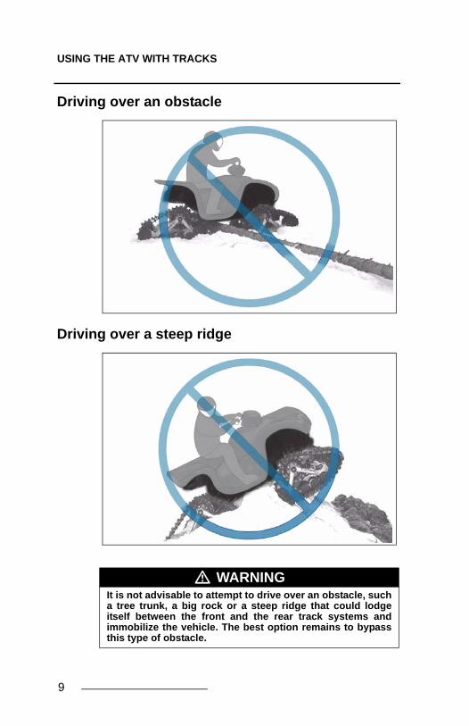
Driving over an obstacle
Driving over a steep ridge
� WARNINGIt is not advisable to attempt to drive over an obstacle, sucha tree trunk, a big rock or a steep ridge that could lodgeitself between the front and the rear track systems andimmobilize the vehicle. The best option remains to bypassthis type of obstacle.
9

USING THE ATV WITH TRACKS
Driving over an obstacle of more than 12 inches
� WARNINGIt is not advisable to attempt to drive over an obstacle ofmore than 12 inches, such a tree trunk, a stump or a largerock. If the situation presents itself, insert a log orappropriately sized rock to decrease the height of theobstacle and facilitate driving over it.
10

USING THE ATV WITH TRACKS
Loading a vehicle into and unloading it from a truck
� WARNINGWhen a vehicle is being loaded into or unloaded from atruck box, it is extremely important to ensure that the fronttracks do not grip the locking gudgeons of the truck’stailgate as this could cause them to tear.
11

USING THE ATV WITH TRACKS
Jumping
Location of the towing cable
� WARNINGIt is strictly forbidden to jump with vehicles equipped withtrack systems. These systems were not designed to carryout this type of operation. An ATV equipped with thesystem must never be used for the following activities:races, rallies, jumps, stunts, acrobatics or any otherextreme applications.
� WARNINGIf your vehicle must be towed out of the snow, never securethe cable on the track systems to tow the vehicle, thetowing cable must be attached to the vehicle frame.
� WARNINGThe driver must remain vigilant and cautious at all times.Powder snow and mud can hide dangerous obstacles.
12

USING THE ATV WITH TRACKS
� WARNINGThe driving characteristics of your ATV will change with theinstallation of the System. It is important to take the time tobecome familliar with the Systems.
� WARNINGIt is the driver’s responsibility to verify that the air intake ofthe vehicle is well adapted to weather conditions and is notblocked by snow accumulation.
� WARNINGWhen travelling in groups, people driving behind vehiclesequipped with a track system should by warned, as thetracks can propel dangerous objects. Be especiallycautious on “rocky” trails.
� WARNINGAdapt your driving style to surrounding conditions(weather, traffic, etc.) and to your driving abilities.
� WARNINGAllow for a greater braking distance and periodically applythe brakes while driving to prevent ice buildup on brakecomponents.
� WARNINGAlways follow the ATV manufacturer's safety rules andregulations regarding, for exemple passengerstransportation, maximum loads, ect.
� WARNINGIt is the driver’s responsibility to follow the recommendedmaintenance schedule described further in this manual.
13

INSTALLATION, REMOVAL AND RE-INSTALLATION
INSTALLATION, REMOVAL AND RE-INSTALLATION
Always follow good shop practices. The place where you will beworking must be security, clean, bright and well ventilated. Ifyou are to use a floor jack, never use it as a stand. Always useappropriate stands. To avoid vehicle movement duringoperations, place blocks behind wheels that remain in contactwith the ground. These recommendations also apply whenremoving parts.
Read this manual before proceeding with the installationwork. Read the “Installation Guidelines” included with theSystem for installation instructions dedicated to your ATVmodel.
When the system is removed and when the wheels arereinstalled on vehicle, make sure that you reinstall all thecomponents of origin (wheels, guards, etc.) such as theywere in the initial condition on the vehicle.
� WARNINGNever place body parts under the vehicle unless it issecurely placed on appropriate stands. Severe injuriescould occur if the vehicle collapses or moves. Do not use alifting device as a secure stand.
� WARNINGBefore beginning the installation, ensure you that thevehicle is immobilized and that the engine is stopped.
� WARNINGTo avoid any potential burn injury, allow the engine andexhaust pipes to cool before beginning installation of thesystem.
14

INSTALLATION, REMOVAL AND RE-INSTALLATION
InstallationExecute all tasks described in Installation Guidelines of thevehicle model. Then, proceed to adjust the angle of attack,alignment and track tension as described in this manual. Testdrive the ATV and the adjustments must be verified a secondtime after the first use, re-adjust as required.
RemovalCAUTION: Leaving anchor brackets attached to suspensionarms when the ATV rides on wheels can result in gravedamage to the vehicle. Never leave components other than theskid plate and foot rest reinforcement parts.
Using a lifting device, raise the ATV and install appropriatestands. Ensure that the vehicle is immobilized and safe to workon.
� WARNINGTo avoid any injury to your hands during manipulation ofthe systems, we recommend handling the systems withhands placed on the frame at the positions shown in thefigure below.
15

INSTALLATION, REMOVAL AND RE-INSTALLATION
• Remove the anti-rotation bracket cover (1) but keepthe anchor bracket (2) attached to the anti-rotationdevice on the track system.
NOTE: Leave anchor bracket (2) attached to stabilizing rod (3).
Figure 1
• Remove track systems.
• Re-install wheels.
16

INSTALLATION, REMOVAL AND RE-INSTALLATION
Re-installation
Always clean wheel hubs on the ATV before installing wheels ortrack systems.
Figure 2
NOTE: Clean wheel hubs.
• Re-install track systems at the rear.
• Re-install track systems at the front.
• Tighten fasteners in criss-cross pattern to themanufacturer’s recommended torque specification.
• Verify track tension. Adjust if required.
• Verify angle of attack. Adjust if required.
• Verify alignment. Adjust if required.
17

ADJUSTMENTS
ADJUSTMENTS
NOTE: To make the following adjustements, position the vehicle on aflat and level surface
Angle of attack for front tracks systemsTo obtain the correct angle of attack on front tracks systems,perform the following:
• Use handlebars to point tracks straight ahead.
• Temporarily apply pressure to the front of the track tomake sure that it stays flat on the ground.
• Stabilizing arm (1) must be attached to the front anchorbracket (2) installed on the vehicle. See Figure 3.
Figure 3
IMPORTANTVerifying your adjustments on the system is mandatoryafter the first use of the vehicle, the track tension,alignment and angle of attack of the each track systemmust be re-verified. Incorrect adjustments can decreasethe performance of the system and create premature wearof certains components
18

ADJUSTMENTS
• Verify that spring assembly bolt (1) is tightened to therecommended torque [40 N•m] and that stabilizing armcomponents are installed in the correct order. SeeFigure 4.
Figure 4
• Position a flat bar across both rear wheels of front tracksystem and measure from the ground up to flat bar asshown on Figure 5.
.
Figure 5
19

ADJUSTMENTS
• Loosen jam nut (1). Adjust length of rod end (2) byrotating the stabilizing arm (3) to obtain 270 mm [10 5/8 in] above the ground. Refer to Figure 6.
NOTE: Before each measurement, temporarily apply light pressure tothe front of the track to make sure that it stays flat on the ground.
.
Figure 6
• When angle of attack is correctly set, tighten the jamnut (1) back against the stabilizing arm. See Figure 7.
Figure 7
20
ADJUSTMENTS
Basic Tuning (front track systems):
• An adjustment of more than 270 mm [10 5/8 in],measured with the flat bar, provides easier steering andproduces a wobbling effect at high speed.
• An adjustment of less than 270 mm [10 5/8 in],measured with the flat bar, results in harder steeringand more stability at high speed.
NOTE: Once adjustment of the angle of attack on the front systems iscompleted, verify once again to confirm the adjustment.
21
ADJUSTMENTS
22
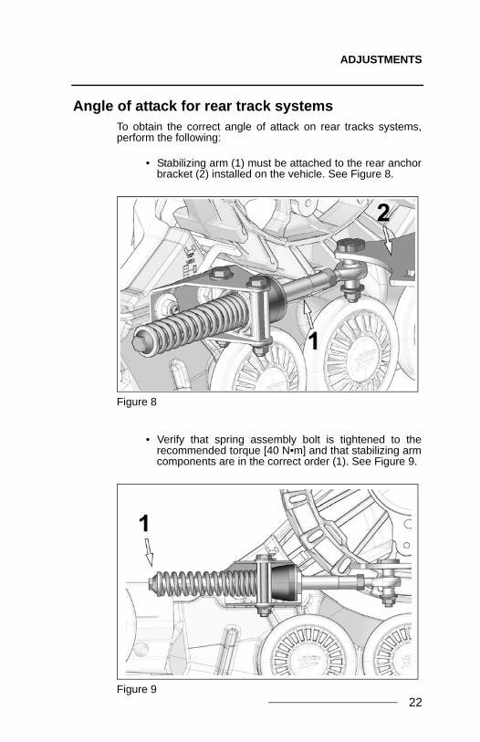
Angle of attack for rear track systemsTo obtain the correct angle of attack on rear tracks systems,perform the following:
• Stabilizing arm (1) must be attached to the rear anchorbracket (2) installed on the vehicle. See Figure 8.
Figure 8
• Verify that spring assembly bolt is tightened to therecommended torque [40 N•m] and that stabilizing armcomponents are in the correct order (1). See Figure 9.
Figure 9

ADJUSTMENTS
• Loosen anti-rotation bracket bolts (1) and (2) to allowthe anti-rotation retainer (3) to rotate on its axis. SeeFigure 10.
Figure 10
• Loosen jam nut (1). Rotate the stabilizing arm to adjustlength of rod end so that no pressure is applied to therubber cone (2). Refer to Figure 11.
Figure 11
23

ADJUSTMENTS
• Position the anti-rotation retainer at 90o (perpendicular)with the stabilizing rod. Tighten the two anti-rotationbracket mounting bolts (1 and 2) to 50 N•m of torque.Refer to Figure 12.
Figure 12
• Turn stabilizing arm nut to adjust length of rod end (1)so that rubber cone (2) applies light pressure onanti–rotation retainer (3). See Figure 13.
Figure 13
24
ADJUSTMENTS
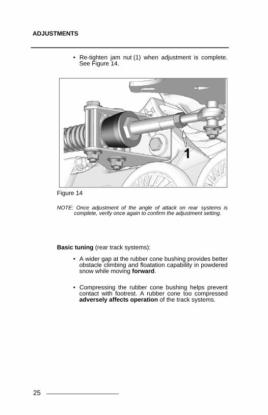
• Re-tighten jam nut (1) when adjustment is complete.See Figure 14.
Figure 14
NOTE: Once adjustment of the angle of attack on rear systems iscomplete, verify once again to confirm the adjustment setting.
Basic tuning (rear track systems):
• A wider gap at the rubber cone bushing provides betterobstacle climbing and floatation capability in powderedsnow while moving forward.
• Compressing the rubber cone bushing helps preventcontact with footrest. A rubber cone too compressedadversely affects operation of the track systems.
25

ADJUSTMENTS
Alignment
Parallelism must be adjusted with the ATV on the ground,driving forward on about 3 m [10 ft] and measuring toe-indistance. Refer to Figure 15.
NOTE: Every time the measurement has to be verified, drive in reverse,then, drive forward again on about 3 m [10 ft].
NOTE: Verify condition of the steering system components beforeadjusting parallelism. Damaged components can prevent properadjustment and impair good operation of the system
Figure 15
Dimension A: Represents the distance between the outer front idler wheels.
Dimension B: Represents the distance between the outer back idler wheels.
A - B = ± 3 mm [1/8 in]
26

ADJUSTMENTS
To perform adjustments on the ATV, first unlock the nut (1) ofeach tie rod end on the ATV. Then screw or unscrew the rod link(2) equally on both sides of the vehicle.
Figure 16
27

ADJUSTMENTS
Rubber track tension
To adjust the track tension, loosen the track tensionner nylonnut (1) and loosen jam nut to unlock adjustment nut (2). Turnthe 14 mm adjustment nut (2) clockwise or counter-clockwise toadjust the track tension to the recommended specification.
Figure 17
When the track tension adjustment is done, lock adjustment nutwith jam nut and tighten the track tensionner assembly nut (1)to the recommended torque.
NOTE: Refer to the exploded views to obtain the recommendedtightening torque .
28

ADJUSTMENTS
29
The following table indicates the force (1) applied and thedeflection (2) which must occur according to the conditions ofuse.
NOTE: Use a tension testing tool such as the one shown in Figure 18.
Figure 18
Figure 19
Season Track Force Deflection
Front 15 kg 19 mm
Rear 15 kg 19 mm
Front 11 kg 19 mm
Rear 11 kg 19 mm
Summer
Winter (snow)

ADJUSTMENTS
Basic tuning
• A higher rubber track tension reduces the risk of“derailing” and reduces drive “ratcheting”.
• A lower rubber track tension provides betterperformance, better rolling and better fuel economy.
Final check
Ride at slow speed for approximately 1.5 km. Evaluate tracksystem performance and re-adjust as required.
30

INSTALLATION OF A RUBBER TRACK
INSTALLATION OF A RUBBER TRACK
If possible, position the vehicle on a flat and level surface (or ona suitable lift device). Turn off the engine.
Proceed as follows:
• Loosen track tensionner assembly nut (1).
• Unlock the two 14 mm nuts (2) on the tensionner rodand unscrew them to slide tensioner assembly back tominimum track tension position.
Figure 20
31

INSTALLATION OF A RUBBER TRACK
32
• Remove the two 202 mm wheels from the tracktensioner. Refer to Figure 21.
Figure 21
• Install the rubber track. Refer to Figure 22.
NOTE: Look for the mark on the track indicating the correctorientation.
Figure 22
• Re-install the 202 mm wheels.
• Adjust track tension. Refer to "Rubber track tension” onpage 28.

BREAK-IN PERIOD
BREAK-IN PERIOD
A break-in period is necessary in order to allow the componentsof the system to settle themselves in relation to each other.
During the break-in period (4 hours or 80 kilometers), followthese recommendations:
• Avoid riding under dry and clean conditions. (Forexample: asphalt, hay or straw field, etc).
• Start sharp turns at very low speed: (15 km/h maximumreal speed).
A GOOD break-in period must be done in a lubricatedenvironment such as water, mud, snow, soft soil, sand, dust,etc.
A BAD break-in period can generate smoke, odors of burnedrubber as well as plastic deposits on the sprocket and/or theframe.
1ST
HOUR 2ND
HOUR 3RD
HOUR
15 km/h MAX 25 km/h MAX 35 km/h MAXREAL SPEED REAL SPEED REAL SPEED
VISUAL INSPECTION X X X XTRACK TENSION X XANGLE OF ATTACK X XALIGNMENT X XBOLT TORQUE X
VERIFICATION INSTALLATION
BREAK-IN PERIOD
33

MAINTENANCE SCHEDULE
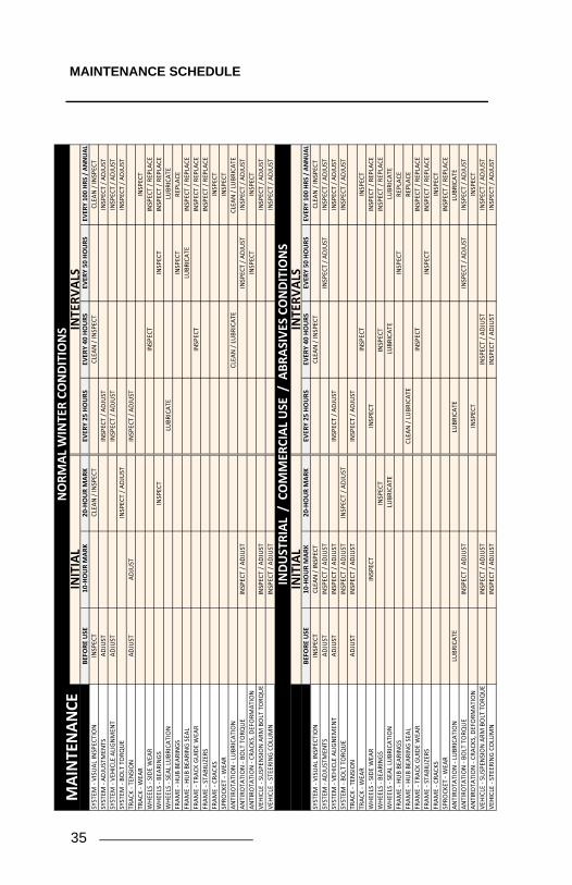
MAINTENANCE SCHEDULE
NOTE: It is recommended not using a brake cleaning solvent to cleanthe track system. This may damage sealing components andstickers.
For optimum performance and maximum durability, please referto the maintenance chart on the following page:
For more details on the maintenance program, consultMaintenance specifications on page 36.
� WARNINGDo not insert hands or feet into or near the System unlessthe engine is off, and the vehicle is stopped with thesecurity brake engaged. .
� WARNINGRegular inspection, adjustment and lubrication of the tracksystems is essential to their good running order and safeoperation. The user is responsible for maintaining andregularly adjusting their track systems. The “Maintenance”section provides the necessary information to performadequate maintenance on the track systems.
� WARNINGFailure to do regular maintenance at the prescribedintervals and perform the preventative adjustmentsindicated in the maintenance schedule can result inpremature wear and important breakage on the tracksystems that will not be covered under the warranty. Theuser is responsible to follow the maintenance scheduleprovided by the manufacturer.
34
MAINTENANCE SCHEDULE
BEFORE
USE
10-
HOU
R M
ARK
20-H
OU
R M
ARK
EVER
Y 25
HO
URS
EVER
Y 40
HO
URS
EVER
Y 50
HO
URS
EVE
RY 1
00 H
RS /
AN
NU
ALSY
STEM
- VI
SUAL
INSP
ECTI
ON
INSP
ECT
CLEA
N /
INSP
ECT
CLEA
N /
INSP
ECT
CLEA
N /
INSP
ECT
SYST
EM -
ADJU
STM
ENTS
ADJU
STIN
SPEC
T / A
DJU
STIN
SPEC
T / A
DJU
STSY
STEM
- VE
HICL
E AL
IGN
MEN
TAD
JUST
INSP
ECT
/ ADJ
UST
INSP
ECT
/ ADJ
UST
SYST
EM -
BOLT
TO
RQU
EIN
SPEC
T / A
DJU
STIN
SPEC
T / A
DJU
STTR
ACK
- TEN
SIO
N
ADJU
STAD
JUST
INSP
ECT
/ ADJ
UST
TRAC
K - W
EAR
INSP
ECT
WHE
ELS
- SID
E W
EAR
INSP
ECT
INSP
ECT
/ REP
LACE
WHE
ELS
- BEA
RIN
GSIN
SPEC
T IN
SPEC
TIN
SPEC
T / R
EPLA
CEW
HEEL
S - S
EAL
LUBR
ICAT
ION
LU
BRIC
ATE
LU
BRIC
ATE
FRAM
E - H
UB
BEAR
INGS
INSP
ECT
REPL
ACE
FRAM
E - H
UB
BEAR
ING
SEAL
LUBR
ICAT
EIN
SPEC
T / R
EPLA
CEFR
AME
- TRA
CK G
UID
E W
EAR
INSP
ECT
INSP
ECT
/ REP
LACE
FRAM
E - S
TABI
LIZE
RS
INSP
ECT
/ REP
LACE
FRAM
E - C
RACK
SIN
SPEC
TSP
ROCK
ET -
WEA
RIN
SPEC
TAN
TIRO
TATI
ON
- LU
BRIC
ATIO
NCL
EAN
/ LU
BRIC
ATE
CLEA
N /
LUBR
ICAT
E AN
TIRO
TATI
ON
- BO
LT T
ORQ
UE
INSP
ECT
/ ADJ
UST
INSP
ECT
/ ADJ
UST
INSP
ECT
/ ADJ
UST
ANTI
ROTA
TIO
N -
CRAC
KS, D
EFO
RMAT
ION
INSP
ECT
INSP
ECT
VEHI
CLE
- SU
SPEN
SIO
N A
RM B
OLT
TO
RQU
EIN
SPEC
T / A
DJU
STIN
SPEC
T / A
DJU
STVE
HICL
E - S
TEER
ING
COLU
MN
INSP
ECT
/ ADJ
UST
INSP
ECT
/ ADJ
UST
BEFO
RE U
SE10
-HO
UR
MAR
K20
-HO
UR
MAR
KEV
ERY
25 H
OU
RSEV
ERY
40 H
OU
RSEV
ERY
50 H
OU
RS E
VERY
100
HRS
/ A
NN
UAL
SYST
EM -
VISU
AL IN
SPEC
TIO
NIN
SPEC
TCL
EAN
/ IN
SPEC
TCL
EAN
/ IN
SPEC
TCL
EAN
/ IN
SPEC
TSY
STEM
- AD
JUST
MEN
TSAD
JUST
INSP
ECT
/ ADJ
UST
INSP
ECT
/ ADJ
UST
INSP
ECT
/ ADJ
UST
SYST
EM -
VEHI
CLE
ALIG
NEM
ENT
ADJU
STIN
SPEC
T / A
DJU
STIN
SPEC
T / A
DJU
STIN
SPEC
T / A
DJU
STSY
STEM
- BO
LT T
ORQ
UE
INSP
ECT
/ ADJ
UST
INSP
ECT
/ ADJ
UST
INSP
ECT
/ ADJ
UST
TRAC
K - T
ENSI
ON
AD
JUST
INSP
ECT
/ ADJ
UST
INSP
ECT
/ ADJ
UST
TRAC
K - W
EAR
INSP
ECT
INSP
ECT
WHE
ELS
- SID
E W
EAR
INSP
ECT
INSP
ECT
INSP
ECT
/ REP
LACE
WHE
ELS
- BEA
RIN
GS
INSP
ECT
INSP
ECT
INSP
ECT
/ REP
LACE
WHE
ELS
- SEA
L LU
BRIC
ATIO
N L
UBR
ICAT
E L
UBR
ICAT
E L
UBR
ICAT
EFR
AME
- HU
B BE
ARIN
GSIN
SPEC
TRE
PLAC
EFR
AME
- HU
B BE
ARIN
G SE
ALCL
EAN
/ LU
BRIC
ATE
REPL
ACE
FRAM
E - T
RACK
GU
IDE
WEA
RIN
SPEC
TIN
SPEC
T / R
EPLA
CEFR
AME
- STA
BILI
ZERS
INSP
ECT
INSP
ECT
/ REP
LACE
FRAM
E - C
RACK
SIN
SPEC
TSP
ROCK
ET -
WEA
RIN
SPEC
T / R
EPLA
CEAN
TIRO
TATI
ON
- LU
BRIC
ATIO
NLU
BRIC
ATE
LUBR
ICAT
E LU
BRIC
ATE
ANTI
ROTA
TIO
N -
BOLT
TO
RQU
EIN
SPEC
T / A
DJU
STIN
SPEC
T / A
DJU
STIN
SPEC
T / A
DJU
STAN
TIRO
TATI
ON
- CR
ACKS
, DEF
ORM
ATIO
NIN
SPEC
TIN
SPEC
TVE
HICL
E - S
USP
ENSI
ON
ARM
BO
LT T
ORQ
UE
INSP
ECT
/ ADJ
UST
INSP
ECT
/ ADJ
UST
INSP
ECT
/ ADJ
UST
VEHI
CLE
- STE
ERIN
G CO
LUM
NIN
SPEC
T / A
DJU
STIN
SPEC
T / A
DJU
STIN
SPEC
T / A
DJU
ST
NO
RMAL
WIN
TER
CON
DITI
ON
SM
AIN
TEN
ANCE
INIT
IAL
INTE
RVAL
S
INIT
IAL
INTE
RVAL
S IN
DUST
RIAL
/ C
OM
MER
CIAL
USE
/ A
BRAS
IVES
CO
NDI
TIO
NS
35

MAINTENANCE SCHEDULE
Maintenance - Tasks
• Inspect: Component(s) must be examined with care. If ananomaly is noticed, the malfunctioning component(s) must berepaired or replaced.
• Clean: Component(s) must be cleaned of any dirt, dust orcontaminant liable to impair the proper operation of the tracksystem.
• Adjust: Component(s) must be adjusted or re-adjustedaccording to the manufacturer’s adjustmentrecommendations. Refer to the relevant section of the UserManual.
• Lubricate: Component(s) need to be lubricated according tothe manufacturer’s recommendations. Refer to the relevantsection of the User Manual.
• Replace: Component(s) must be replaced to avoid seriousbreakage.
Maintenance - Specifications
System
• Visual inspection: Visually inspect each track system todetect any defect or anomaly that can impair properfunctioning of the systems.
• Adjustment : Perform or verify the attack angle adjustmentson the systems according to the manufacturer’srecommendations. Refer to the “Adjustments” section of theUser Manual on page 18.
• Vehicle alignment: Make or verify the adjustments (vehiclealignment) on the systems according to the manufacturer’srecommendations. Refer to the “Alignment” section of theUser Manual on page 26.
• Bolt torque: Check the torque of critical bolts identified in theexploded views of the system. Refer to the central pages ofthe User Manual.
NOTE: Comply with the tightening torque recommendations and usethreadlocker liquid if you come across a bolt not tightened to themanufacturer’s recommendations.
36

MAINTENANCE SCHEDULE
Track
• Tension: Perform or check track tension on the systemsaccording to the manufacturer’s recommendations. Refer tothe “Rubber track tension” section of the User Manual onpage 28.
• Wear: Check wear and overall condition of the tracks on thesystems. Refer to the “Wear” section of the User Manual onpage 52.
NOTE: A damaged track can result in premature wear of the system’scomponents.
Wheels
• Side wear: Check side wear on system’s wheels. Refer tothe “Wear” section of the User Manual on page 50. Replacewheel(s) if wear is too great.
• Bearings: Check wheel bearings for restriction, noise orabnormal play in rotation. Replace wheel if it shows one ofthese defects.
• Wheel seal lubrication: Wheel seals must be cleaned of anydirt or contaminant and lubricated according to themanufacturer’s recommendations. Refer to the “Lubrication”section of the User Manual on page 41. If a seal showsdamage or any defect, it must be replaced.
NOTE: Lubrication done at the recommended intervals allows thewheel seals to maintain optimal sealing action and prolongs theuseful lifespan of the wheels.
Frame
• Hub bearings: Check hub bearings for restriction, noise orabnormal play in rotation. Bearings must absolutely bereplaced if they present a defect.
NOTE: Always replace both bearings at the same time whenreplacement of a bearing is performed.
• Hub bearing seal: The maintenance chart recommendscleaning and lubricating the hub seal. Refer to the“Lubrication” section of the User Manual on page 42.
NOTE: Lubrication done at the recommended intervals allows the hubseal to maintain optimal sealing action and prolongs the lifespanof the hub bearings.
37

MAINTENANCE SCHEDULE
• Track guide wear: Check wear on track guides. Refer to the“Wear” section of the User Manual on page 52. Replaceguides if wear is too great.
• Stabilizers: Verify condition of rubber cones on the stabilizerassembly of front systems and wheel axle assembly of rearsystems. If the cone bores show oval-shaped wear, theymust be replaced.
• Cracks: Visually inspect the frames for presence of cracks ordefects that can impair proper operation of the systems.Replace components if damaged.
Sprocket
• Wear: Check wear of sprockets on the systems. Refer to the“Wear” section of the User Manual on page 53. Replace ifwear is too great.
Anti-rotation
• Lubrication: The maintenance chart recommends cleaningand lubricating the anti-rotation arms. Refer to the“Lubrication” section of the User Manual on page 48.
• Bolt torque: Verify torque of assembly bolts on anchorbrackets and anti-rotation arms at the recommended intervalsspecified by the maintenance chart.
• Cracks, bent parts: Visually inspect anti-rotation arms forpresence of cracks or bent parts that can impair properfunctioning. Replace components if damaged.
38

MAINTENANCE SCHEDULE
CAUTION: When pressure washing the track systems, caremust be taken to keep the water stream away from wheelbearing seals and rubber caps.
CAUTION: If stabilizer rubber cone bores show sign of wearand oval deformation, they must be replaced along with thebolt and washer.
CAUTION: Hub bearings should be checked, and replaced asneeded. Bearings that make noise and restrict rotation of hubare indications that they must be replaced.
CAUTION: Stabilizing rod and spring should be greased with alubricant like motorcycle chain lube or its equivalent.
� WARNINGAfter use in an extreme environment (mud and water) and atannual inspection of all bearings, please remember that thebearings cannot be re-greased like snowmobile bearings. Ifthey need to be serviced, replace the wheel completely.Some of the components (i.e. 134 mm wheels) need aspecial tool for servicing. Please use appropriate tools toavoid any damage to your component.
39

LUBRICATION
LUBRICATION
40

LUBRICATION
LUBRICATION
The Maintenance Schedule chart on page 35 includeslubrication maintenance that should be performed on tracksystems. Refer to the following recommendations foroptimal lubrication.
NOTE: Use a water-resistant anti-friction synthetic grease. AerochemMF grease is recommended.
REFERENCE “A”
LUBRICATION OF 134 mm AND 202 mm WHEELS
Apply evenly 1 to 1.5 cc (cubic centimeter) of grease over theentire circumference (360°) of the inner steel washer.
41

LUBRICATION
REFERENCE “B”
LUBRICATION OF HUB BEARING SEALS
Apply evenly 1.5 to 2 cc (cubic centimeter) of grease betweenthe hub seal’s lips and over its the entire circumference (360°)
IMPORTANT : The hub seal must not extend beyond the hubface. It should be installed flush with the hub face.
42

LUBRICATION
REFERENCE “C”
LUBRICATION OF THE HUB SPEED SLEEVE
Apply 1 to 1.5 cc (cubic centimeter) of grease over the entirewidth and circumference (360°) of the hub speed sleeve.
43

LUBRICATION
REFERENCE “D”
HUB LUBRICATION
Remove small bolt on top of the system’s frame and pour 10 to12 cc of 80w90 grade oil on hub shaft through tapped hole.
� WARNINGBe careful not to use too much oil. An excessive amount ofoil could damage the seal and cause oil leakage.
44

LUBRICATION
REFERENCE “E”
STABILIZER SHAFT LUBRICATION
Apply evenly 1 to 1.5 cc (cubic centimeter) of grease all around(360°) the stabilizer shaft and over its entire length.
45

LUBRICATION
REFERENCE “F”
STABILIZER BORE LUBRICATION
Apply evenly 1 to 1.5 cc (cubic centimeter) of grease inside thestabilizer shaft bore, over its entire length and circumference(360°).
46

LUBRICATION
REFERENCE “G”
STABILIZER BOLT HEAD LUBRICATION
Apply evenly 0.75 to 1.5 cc (cubic centimeter) of grease on thestabillizer mounting bolt head. Apply over the entirecircumference (360°).
47

LUBRICATION
48
REFERENCE “H”
LUBRICATION OF STABILIZING ARMS
Apply spray lubricant (e.g. motorcycle chain grease) all aroundthe stabilizing arm compression spring and over its entirelength.
FRONT SYSTEMS
REAR SYSTEMS

TORQUE SPECIFICATIONS
TORQUE SPECIFICATIONS
Refer to the exploded views at the end of the Manual to obtain torque specifications applied to bolts at important points on the track system.
NOTE: Use a threadlocker (Loctite 263 type or its equivalent) at theindicated places in the exploded views of the system.
STORAGE
The best way to store the System is to lay down each frame onits side, away from direct sunlight.
Figure 23
� WARNINGOvertightening the bolts of some parts may damage themand security features may be affected.
49

WEAR
WEAR
WheelVerify wheel wear especially on the interior guiding strip(see Figure 24). If the internal plastic structure is visible, therubber coating is worn and the wheel must be replaced(see Figure 25), or when the width of the wheel’s rolling bandreaches 17 mm, (see Figure 26: 20.5 mm when new). A wheelthat is excessively worn will not offer enough support for trackguidance.
Figure 24
50

WEAR
Figure 25
Figure 26
51

WEAR
Track guideVerify the wear of the track guide by measuring the width of theguide. If dimensions of the guide illustrated in Figure 27 areless than 5 mm, at any place, replace the part. If the guidingstrips are so worn that the concave shape is no longer visible,replace the part. An overly worn track guide could prematurelywear the other components of guidance of the system.
Figure 27
TrackVerify the wear of the track by inspecting the rolling path, thedriving lug, the profile and the internal and external condition ofthe track's carcass. Make sure that the track’s internal structureare not visible at cuts or worn area. Too much wear could causedamage to the wheels and to the track guide.
52

WEAR
SprocketCheck sprocket wear by measuring the part as illustrated onFigure 28. Replace the part when dimensions are less than19 mm. Excessive wear could lower track drive efficiency andreduce the system’s performance.
Figure 28
53

WEAR
54
Anti-rotationVerify the wear of anti-rotation system, mainly at the ball joint(Figure 29) to make sure that it is not seized or extremely loose.Ball joint damage could harm the performance of the tracksystem.
.
Figure 29
Check if ball rotates freely in ball housing and check also thatthere is not excessive play between ball and ball housing(Figure 30).
Figure 30

TROUBLESHOOTING
TROUBLESHOOTING
Problem Potential cause Correction
Presence of debris in the system.Remove any debris which could prevent the
proper operation of the system
Severe and localized wear of a wheel (flat spot) Replace the part
Frozen sprocket or wheel
Remove the ice/snow build-up. Storing the
vehicle at temperatures higher than 0 °C might be
required. An optional Sprocket Scraper kit is
available. Contact Customer Service.
Beginning of derailing
Check tensioner alignment. Make sure that the
track is well guided by the wheels and the track
guide. Realign the system if it's needed.
The presence of dirt on the ATV during the
installation of the system could cause a bad
seating of mating surfaces of the hubs of the ATV
and the track system.
Remove the system and clean the contact
surfaces between the hubs.
Hub or wheel bearing damaged
Replace the damaged bearing.
(Replacement of bearings is recommended at
100-hour intervals)
Hub of the ATV or of the track system deformed
following an impact or abusive useReplace the deformed part
Incorrect ajustement of the track system's angle
of attack.
Adjust the angle of attack according to the
manufacturer's specifications.
(Refer to the "Adjustments" section of the User
Manual)
Track tension too high
Adjust track tension.
(Refer to the "Adjustments" section of the User
Manual)
Wrong alignment of the system
Correct the system alignment
(Refer to the "Adjustments" section of the User
Manual)
Wheel blocked Try to free the wheel and replace if necessary
Constant turnVary your turning radius and seek areas which
can lubricate the system
Uninterrupted use of the system in paths with rutsVary your line (out of the ruts) and seek zones
which can lubricate the system
Clean the sprocket of mud, snow or any
contaminants build-up. An optional Sprocket
Scraper kit is available. Contact Customer
Service.
Remove ice/snow build up on wheels
Clear frame and wheels of compacted snow.
Infiltration of snow in the air intake system of the
ATV.
Remove snow and immediately contact the
dealer to fix the situation.
Severe wear of one or several components Check tensioner alignment. Check wear on track
guide, inside driving lugs and wheels.
Track tension too low
Adjust track tension on systems.
(Refer to the "Adjustments" section of the User
Manual)
Incorrect alignment of the track system and/or
incorrect angle of attack.
Adjust angle of attack on the systems and vehicle
alignment according to the manufacturer's
specifications.
(Refer to the "Adjustments" section of the User
Manual)
Insufficient snow floatation Incorrect adjustment of anti-rotation arm
Adjust the angle of attack according to the
manufacturer's specifications.
(Refer to the "Adjustments" section of the User
Manual)
TROUBLESHOOTING
Loss of power
Unstable behavior
Partial or total derailing
Abnormal vibration
Overheating of system
guiding components (burned
rubber odor)
Track tension too high
55

SERIAL NUMBER LOCATION
SERIAL NUMBER LOCATION
The following pictures show the location of the serial numbers onthe track system frame (Figure 31) and rubber track(Figure 32).
Figure 31
Figure 32
56

57
’’CE’’ DECLARATION OF CONFORMITY
’’CE’’ DECLARATION OF CONFORMITY
"CE" DECLARATION OF CONFORMITY
WE:
MANUFACTURER : CAMOPLAST SOLIDEAL INC.ADDRESS : 4162, Burrill, Local A
Shawinigan (Québec), Canada
G9N 6T6
PHONE :
FAX :
WEB SITE : www.camoplastsolideal.com
HEREBY DECLARE THAT THE PRODUCT SERIES
PRODUCT : Polaris Prospector Pro ATV
CUSTOMER :
IS IN CONFORMITY WITH THE FOLLOWING STANDARDS
NUMBER : TITLE: DATE:
-EN 62079 Preparation of Instruction 2001
-EN 12100-1 & -2 Safety of Machinery 1996
-EN 17050-1 & -2 Conformity Assessment 2005
AND IN CONFORMITY WITH THE FOLLOWING EC DIRECTIVE:
NUMBER: TITLE: DATE:
2006/42/EEC Safety of machinery directives 2006
DONE AT: Shawinigan (Québec), Canada
PERSON IN-CHARGE:__________________________________________
TITLE:_________________________________________________________
DATE:_______________ SIGNATURE:___________________________________

EXPLODED VIEWS
POLARIS PROSPECTOR PRO ATV

ITEM # PART # DESCRIPTION QTY
A 2205425 KIT- FRAME, CMPLST, CAST, ATV 1
1 -- UPPER CARRIER / SUPPORT SUPÉRIEUR 1
2 -- HUB CAP POLARIS ASSY / CAP DE MOYEU POLARIS 1
3 -- HSBS, M6-1X10, 10.9, ZP 1
4 -- W, 9.9X6X0.9, AL 1
5 -- STICKER WARNING / AUTOCOLLANT AVERTISSEMENT 1
6 -- STICKER / AUTOCOLLANT -- POLARIS ATV 1
7 -- STICKER / AUTOCOLLANT -- PROSPECTOR PRO ATV 1
8 -- ERR, 35, 2.4, ZP, SHR-137 1
9 2205123 HUB BEARING KIT / ENSEMBLE ROULEMENTS POUR MOYEU 1
ITEM # PART # DESCRIPTION QTY
B 2205426 KIT - FRAME, CMPLST, PLASTIC, FRT, ATV 1
1 -- FRONT PLASTIC BASE ASSEMBLY WITH SHAFTS / BASE PLASTIQUE AV.+ ARBRES 1
2 TRACK GUIDE / GUIDE CHENILLE 1
3 RWHS, 6X16, TX, ZP 62205428

ITEM # PART # DESCRIPTION QTY
C 2205427 KIT - FRAME, CMPLST, PLASTIC, RR, ATV 1
1 -- REAR PLASTIC BASE ASSEMBLY WITH SHAFTS / BASE PLASTIQUE ARR.+ ARBRES 1
2 TRACK GUIDE / GUIDE CHENILLE 1
3 RWHS, 6X16, TX, ZP 62205428
ITEM # PART # DESCRIPTION QTY
D 2205433 K-SPROCKET, CMPLST, 18 TOOTH 1
1 -- SPROCKET-CMPLST XP, 18 TOOTH 1
2 -- HFSCS, M10-1.5X30, 10.9, ZP, TL, DIN6921 4

ITEM # PART # DESCRIPTION QTY
E 2205432 K-SPROCKET, CMPLST, 20 TOOTH 1
1 -- SPROCKET-CMPLST XP, 20 TOOTH 1
2 -- HFSCS, M10-1.5X30, 10.9, ZP, TL, DIN6921 4
ITEM # PART # DESCRIPTION QTY
H 2205434 K-HUB, CMPLST, 13mm 1
1 -- HUB-CMPLST XP 13mm, ASSY 1
2 -- HFSCS, M10-1.5X30, 10.9, ZP, TL, DIN6921 4
3 -- ERR, 35, 2.4, ZP, SHR-137 1

ITEM # PART # DESCRIPTION QTY
G 2205435 K-HUB, CMPLST, 32mm 1
1 -- HUB-CMPLST XP 32mm, ASSY 1
2 -- HFSCS, M10-1.5X30, 10.9, ZP, TL, DIN6921 4
3 -- ERR, 35, 2.4, ZP, SHR-137 1
ITEM # PART # DESCRIPTION QTY
H 2205121 K-WHEEL, CMPLST, IDLER, ATV 1
1 -- WHEEL / ROUE -- ATV 134 MM 1
2 -- 2 LIPS CAP, 2" O.D. TUBE / BOUCHON 2 LÈVRES, TUBE DIA EXT 2 PO 1
3 -- HCSW, M10-1.5X25, 8.8, ZP, TL, DIN933 1
4 -- WHEEL SEAL / JOINT D'ÉTANCHÉITÉ -- (25 ID X 42 OD) 1
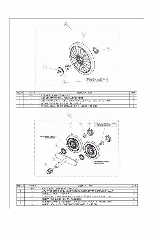
ITEM # PART # DESCRIPTION QTY
i 2205122 K-WHEEL, CMPLST, MID, ATV 1
1 -- 202 MM ATV WHEEL / ROUE ATV 202 MM 1
2 -- 2 LIPS CAP, 2" O.D. TUBE / BOUCHON 2 LÈVRES, TUBE DIA EXT 2 PO 1
3 -- HCSW, M10-1.5X25, 8.8, ZP, TL, DIN933 1
4 -- WHEEL SEAL / JOINT D'ÉTANCHÉITÉ -- (25 ID X 42 OD) 1
ITEM # PART # DESCRIPTION QTY
J 2205431 K-ROCKER, CMPLST, OUTER, ATV 1
1 -- ATV STABILIZER ASSY MALE / STABILISATEUR VTT ASSEMBLÉ, MALE 1
2 -- WHEEL / ROUE -- 134mm ATV 2
3 -- 2 LIPS CAP, 2" O.D. TUBE / BOUCHON 2 LÈVRES, TUBE DIA EXT 2 PO 2
4 -- HCSW, M10-1.5X25, 8.8, ZP, TL, DIN933 2
5 -- RUBBER CONE, STABILIZER / CÔNE CAOUTCHOUC, STABILISATEUR 1
6 -- WHEEL SEAL / JOINT D'ÉTANCHÉITÉ -- (25 ID X 42 OD) 2

ITEM # PART # DESCRIPTION QTY
K 2205430 K-ROCKER, CMPLST, INNER, ATV 1
1 -- ATV STABILIZER FEMALE ASS'Y / STABILISATEUR VTT ASSEMBLÉ, FEMELLE 1
2 -- DUST CAP, STABILIZER / CAPUCHON, STABILISATEUR 1
3 -- HCS, M10-1.5X45, 10.9, ZP, TL, DIN931 1
4 -- W, 7/16X1.0X0.072, 8, ZP, USS 1
ITEM # PART # DESCRIPTION QTY
L 2205123 KIT - BEARINGS, CMPLST, ATV 1
1 -- INTERNAL SPACER / ESPACEUR ROULEMENTS 1
2 -- STANDARD BEARING / ROULEMENT À BILLES STANDARD 2
3 -- SHAFT SEAL / JOINT D'ÉTANCHÉITÉ, ARBRE MOYEU -- 50 x 62 x 10 TC 1
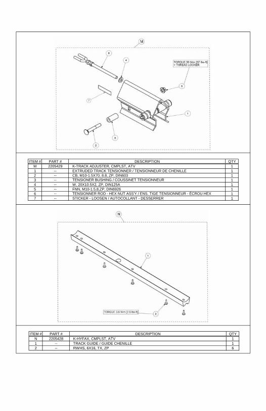
ITEM # PART # DESCRIPTION QTY
M 2205429 K-TRACK ADJUSTER, CMPLST, ATV 1
1 -- EXTRUDED TRACK TENSIONNER / TENSIONNEUR DE CHENILLE 1
2 -- CB, M10-1.5X70, 8.8, ZP, DIN603 1
3 -- TENSIONER BUSHING / COUSSINET TENSIONNEUR 1
4 -- W, 20X10.5X2, ZP, DIN125A 1
5 -- FNN, M10-1.5,8,ZP, DIN6926 1
6 -- TENSIONNER ROD - HEX NUT ASS'Y / ENS. TIGE TENSIONNEUR - ÉCROU HEX 1
7 -- STICKER - LOOSEN / AUTOCOLLANT - DESSERRER 1
ITEM # PART # DESCRIPTION QTY
N 2205428 K-HYFAX, CMPLST, ATV 1
1 -- TRACK GUIDE / GUIDE CHENILLE 1
2 -- RWHS, 6X16, TX, ZP 6

ITEM # PART # DESCRIPTION QTY
O 2205438 KIT- ANTI ROTATION, CMPLST, ATV 1
1 -- SHORT ANTI-ROTATION TUBING WELDMENT / TUBE ANTI-ROTATION COURT, SOUDÉ 1
2 -- HCS, M10-1.5X60, 10.9, ZP, DIN931 1
3 -- HFSCS, M12-1.75X50, 8.8, ZP, FULL THREAD 1
4 -- X-LONG ROD END / TIGE À ŒIL X-LONG 1
5 -- BUSHING SPACER / BAGUE ESPACEUR -- 3/8'' 2
6 -- W, 374X13X3, ZP, DIN 9021 1
7 -- W, 7/16X1.0X0.072, 8, ZP, USS 1
8 -- FNN, M10-1.5, 8, ZP, DIN6926 1
9 -- STABILIZING ROD SPRING / RESSORT BRAS STABILISATEUR 1
10 -- RUBBER DAMPER / AMORTISSEUR DE CAOUTCHOUC 1
ITEM # PART # DESCRIPTION QTY
P 2205452 K-REAR DAMPER, CMPLST, ATV 1
1 -- HCSW, M10-1.5X25, 8.8, ZP, TL, DIN933 2
2 -- WHEEL AXLE, STABILIZER / AXE DE ROUE, STABILISATEUR 2
3 -- AXLE, REAR STABILIZER / AXE, STABILISATEUR ARRIÈRE 1
4 -- RUBBER CONE, STABILIZER / CÔNE CAOUTCHOUC, STABILISATEUR 2

ITEM # PART # DESCRIPTION QTY
Q 2205125 K-HDWR, CMPLST, ATV 1
1 -- HSBS, M6-1X10, 10.9, ZP 1
2 -- HCSW, M10-1.5X25, 8.8, ZP, TL, DIN933 12
3 -- HFSCS, M10-1.5X30, 10.9, ZP, TL, DIN6921 4
4 -- CB, M10-1.5X70, 8.8, ZP, DIN603 1
5 -- HSFS, M10-1.5X 80, 10.9, ZP 2
6 -- SPACER WASHER / RONDELLE ESPACEUR 2
7 -- TENSIONER BUSHING / COUSSINET TENSIONNEUR -- XT4S 1
8 -- ALIGNMENT SHIM CASTING / CALE D'ALIGNEMENT, SUPPORT SUPÉRIEUR 1
9 -- W, 9.9X6X0.9, AL 1
10 -- W, 20X10.5X2, ZP, DIN125A 1
11 -- W, 1-1/4X3/8X1/8, ZP 2
12 -- NN, M10-1.5, ZP, 8, DIN982 2
13 -- FNN, M10-1.5, 8, ZP, DIN6926 1
14 -- AXLE, REAR STABILIZER / AXE, STABILISATEUR ARRIÈRE 1
15 -- TENSIONNER ROD - HEX NUT ASS'Y / ENS. TIGE TENSIONNEUR - ÉCROU HEX 1
16 -- RUBBER CONE, STABILIZER / CÔNE CAOUTCHOUC, STABILISATEUR 2
17 -- RWHS, 6X16, TX, ZP 6
18 -- ERR, 35, 2.4, ZP, SHR-137 1

ITEM # PART # DESCRIPTION QTY
R 2205448 KIT - ANTIROTATION BRACKET 1
1 -- MAIN PLATE, UNIVERSAL ANTI-ROT. (IS) / PLAQUE PRINCIPALE UNIV. ANTI-ROT. (SI) 1
2 -- HCS, M10-1.5X80, 10.9, ZP, DIN931 2
3 -- W, 25X11X2, 8, ZP, USS 4
4 -- FNN, M10-1.5, 8, ZP, DIN69261 2
5 -- RETAINER, ANTIROTATION / ANTI-ROTATION, PLAQUE PIVOTANTE 1
ITEM # PART # DESCRIPTION QTY
S 2205452 K-DECALS, CMPLST, ATV 1
1 -- HUB CAP POLARIS ASSY / CAP DE MOYEU POLARIS ASSEMBLÉ 1
2 -- STICKER - LOOSEN / AUTOCOLLANT - DESSERRER 1
3 -- STICKER - WARNING / AUTOCOLLANT - AVERTISSEMENT 1
4 -- STICKER / AUTOCOLLANT -- POLARIS ATV 1
5 -- STICKER / AUTOCOLLANT -- PROSPECTOR PRO ATV 1

ITEM # PART # DESCRIPTION QTY
T 2205120 KIT - CAPS 1
1 -- 2 LIPS CAP, 1-3/4" O.D. TUBE / BOUCHON 2 LÈVRES, TUBE DIA EXT 1-3/4 PO 1
2 -- 2 LIPS CAP, 2" O.D. TUBE / BOUCHON 2 LÈVRES, TUBE DIA EXT 2 PO -- LDPE 1
3 -- 2 LIPS CAP, 2" O.D. TUBE / BOUCHON 2 LÈVRES, TUBE DIA EXT 2 PO -- ESPRENE 12
4 -- DUST CAP, STABILIZER / CAPUCHON, STABILISATEUR 1
5 -- HUB CAP POLARIS ASSY / CAP DE MOYEU POLARIS ASSEMBLÉ 1
ITEM # PART # DESCRIPTION QTY
U 5414840 TRACK-CMPLST, FRONT, ATV 1

ITEM # PART # DESCRIPTION QTY
V 5414841 TRACK-CMPLST, REAR, ATV 1
ITEM # PART # DESCRIPTION QTY
W 2205461 RUBBER CONE, STABILIZER / CÔNE CAOUTCHOUC, STABILISATEUR 1
X 2205454 ERR, 35, 2.4, ZP, SHR-137 1
Y TBD SPROCKET SPRAPER / GRATTOIR, BARBOTIN 1


