Page 1
Pole Attachment
and Conduit Usage Guidelines
Procedures, Guidelines and Requirements
Covering the Installation of Communication Cables,
Wireless Equipment, Banners and Seasonal Equipment
on NES Poles and in NES Conduits
Revision 2.13
Issued September 15, 2016
Effective October 15, 2016
Page 2
2
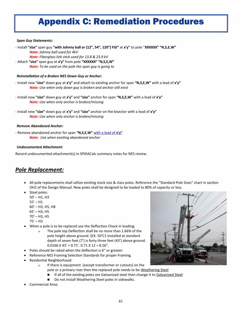
TABLE OF CONTENTS
Section 1: Introduction ................................................................................................. 3
A: Overview ..................................................................................................... 3
B: Definitions .................................................................................................. 4
Section 2: Basic Procedures......................................................................................... 9
A: Process Flow Chart .................................................................................. 11
Section 3: License Application Process ...................................................................... 12
A: Pole Attachment and Licensing Process ............................................... 12
B: Post Installation Inspection .................................................................... 15
C: Cable Identification .................................................................................. 16
D: Expediting Large Projects ....................................................................... 17
Section 4: Conduit Application and Use Requirements ............................................. 18
A: General Requirements ............................................................................ 18
Section 5: Construction Guidelines ............................................................................ 21
A: Inspection Markings ................................................................................ 24
B: Utility Operator Basics ............................................................................. 25
C: Identifying NES Cables ............................................................................ 26
D: Communication Line Clearance Requirements ..................................... 27
E: Attachment Clearance Requirements .................................................... 30
F: Communication Riser Requirements ...................................................... 31
G: Equipment Attachments ......................................................................... 33
H: System Maintenance .............................................................................. 42
Appendix A: Pre-Construction Survey Process Supplement ......................................... 43
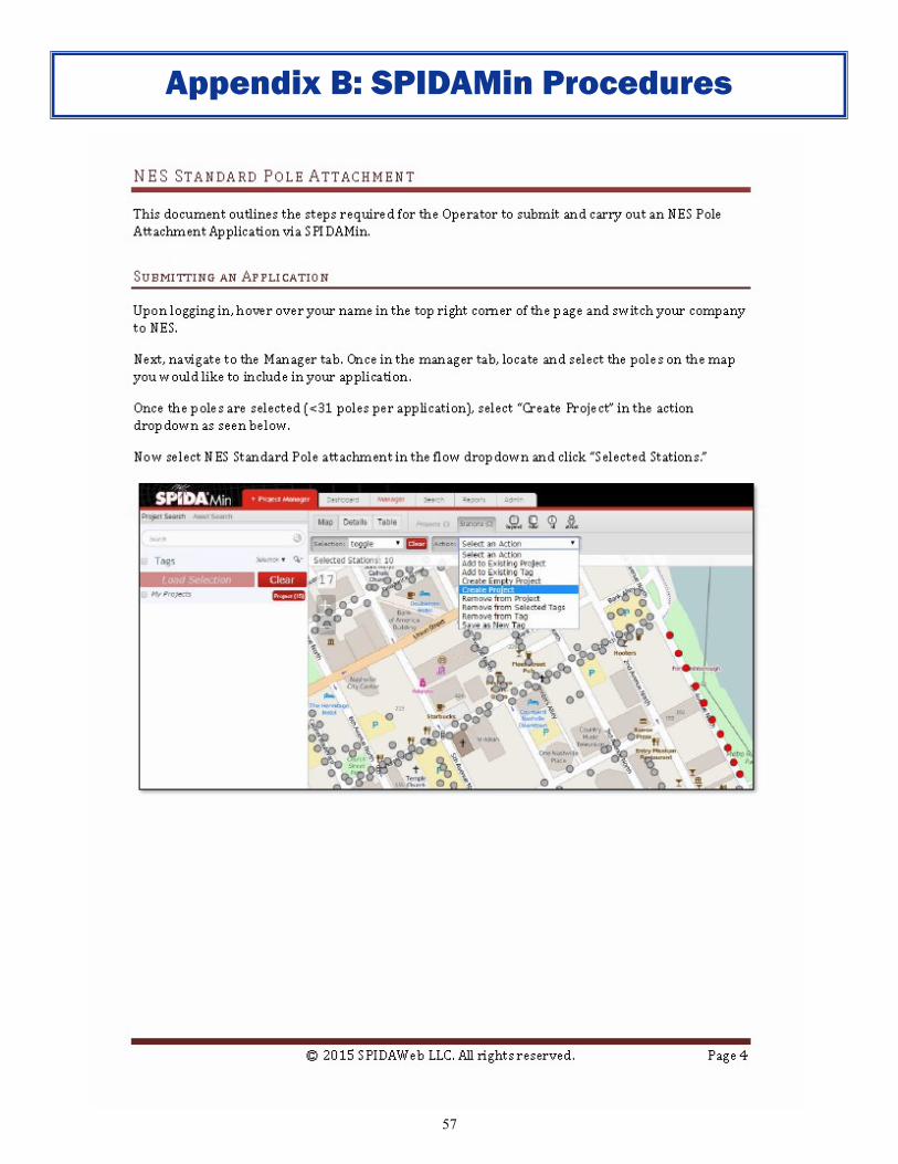
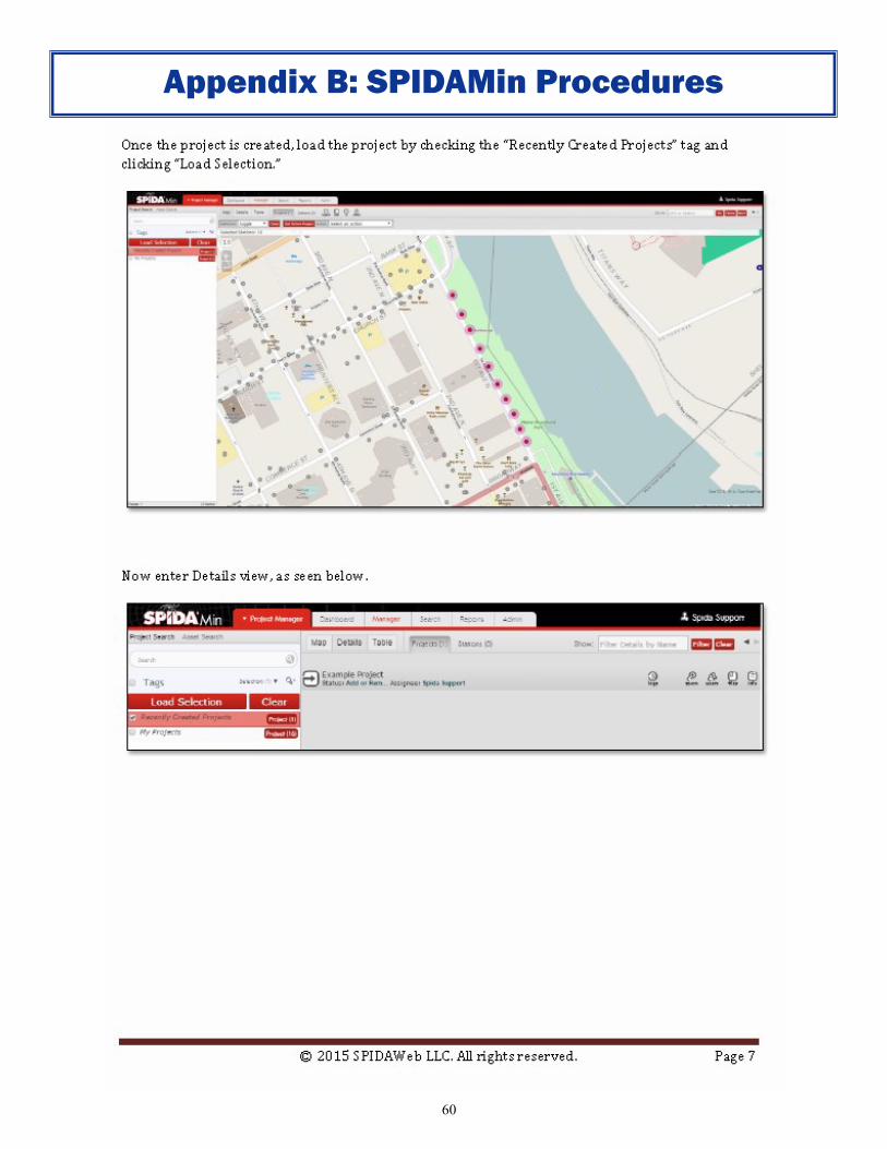
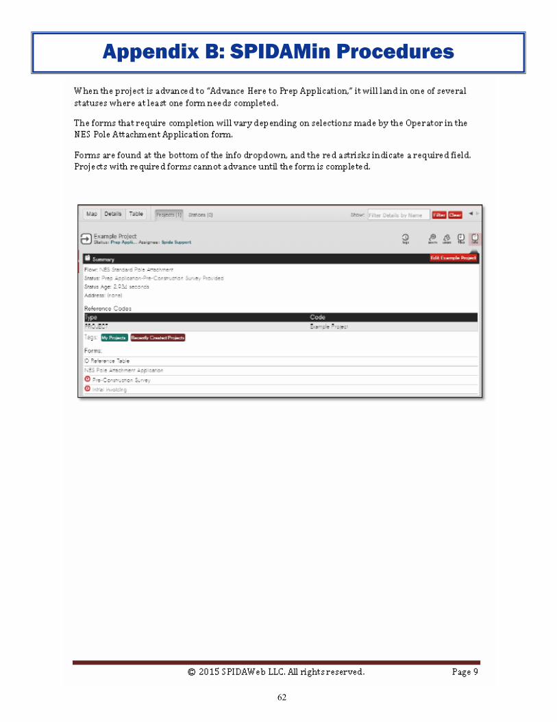
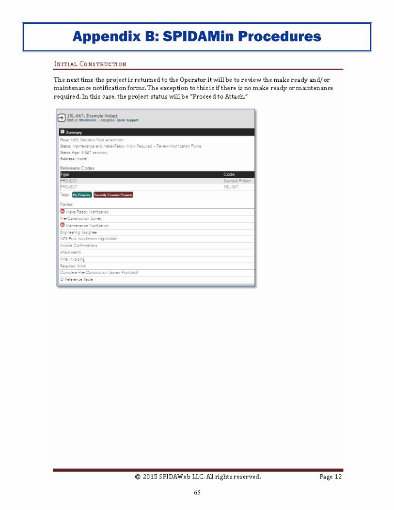
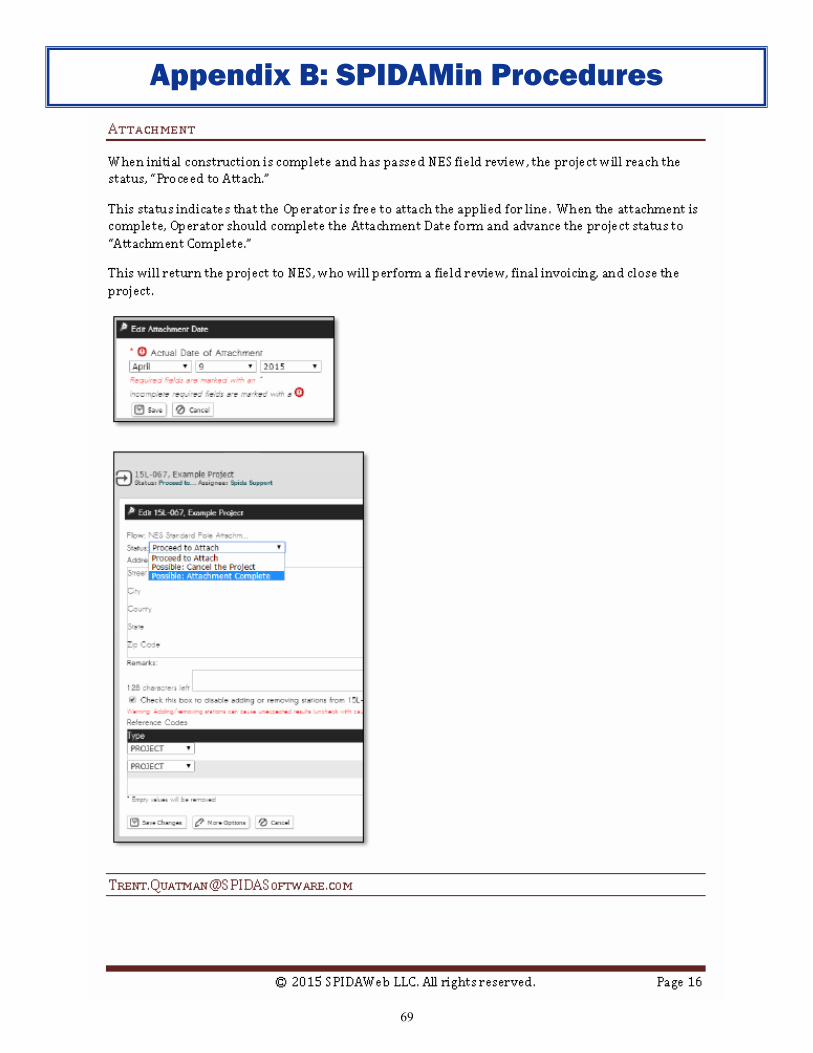
Appendix B: SPIDAMin Procedures ............................................................................... 54
Appendix C: Remediation Procedures ........................................................................... 70
Appendix D: Summary of Changes to this Revision ...................................................... 88
Approvals: Approvals for this Revision ........................................................................ 90
Page 3
3
The information contained in this document is intended to communicate the
requirements for pole attachment requests from companies who have a valid
Infrastructure Use Agreement with Nashville Electric Service (NES). Adherence to these
guidelines, procedures and requirements will improve timeliness of application and
approval processes.
This document outlines situations under which NES considers the attachment of
facilities to its poles and usage of its conduit. It also outlines the requirements and
procedures for granting such permission as well as the physical installation and
maintenance of facilities on NES poles.
It is the responsibility of all organizations that apply for attachment to NES facilities or
use NES conduits to follow all applicable standards.
Nashville Electric Service
Attachments Group
1214 Church Street
Room 347
Nashville, TN 37246
(615) 747-3970
FAX (615) 747-3968
[email protected]
Website: www.nespower.com
A: Overview
1. Introduction
Page 4
4
B: Definitions
1. The following terms, phrases, words, and their derivations shall have the meaning given below.
The words "shall" and "will" are mandatory and "may" is permissive. Words not defined shall be
given their common and ordinary meaning.
1.1 "Anchor" means an anchor owned by NES which is a device to reinforce the pole to which it
is attached by a guy wire.
1.2 "Applicant" means any person who applies to access and make attachment to or otherwise
occupy NES infrastructure.
1.3 “Applicable Standards” means all applicable engineering and safety standards governing
the installation, maintenance, and operation of facilities and the performance of all work
in or around electric infrastructure and includes the most then-current versions of the
National Electrical Safety Code (NESC), as adopted by the State of Tennessee, the
National Electric Code (NEC), and the regulations of the Occupational Safety and Health
Administration (OSHA), “A Local Government Officials Guide to Transmitting Antenna RF
Emissions Safety: Rules, Procedures, and Practical Guidance,” by the Federal
Communications Commission, Local and State Government Advisory Committee, June 2,
2000, each as may be amended from time to time, and/or other reasonable construction,
safety and engineering requirements of NES (including this document) or other federal,
state, or local authority with jurisdiction over NES' infrastructure.
1.4 "Application" means an application by the operator to install an attachment.
1.5 "Attachment" means with respect to the operator, wireline facilities or wireless equipment
affixed to or placed within NES infrastructure to provide communications services, and as
further designated in the application and with respect to other users, any communications
or electric facilities or equipment affixed to or placed within NES infrastructure.
1.6 "Cable" means any communications cable, wire, or strand, including without limitation
fiber optic cable, coaxial cable, and twisted pair copper cable.
1.7 "Communications System" or "System" means the operator's wire line facilities, including
but not limited to cables and electronics, as well as any and all associated equipment and
facilities owned or controlled by the operator to provide any communications services,
and attached to NES infrastructure.
1.8 “Communications Space” means the vertical space, agreed upon by joint and/or
infrastructure use agreements, identified on the pole below the communication worker
safety zone onto which communication facility attachments can be made.
1.9 "Conduit Attachment" means an attachment consisting of a single communications cable
or other object occupying one linear foot of a single conduit, duct, innerduct, or other
enclosed structure in NES' underground conduit system.
1.10 "Conduit System" means all the underground conduits owned by NES.
1.11 “Communication Worker Safety Zone” (CWSZ) means as defined in the NESC, section
235C4.
1. Introduction
Page 5
5
1.12 “Corrections” shall mean any of the operator's facilities found to be in violation of the
applicable standards. The operator shall use all reasonable efforts to correct such
violation immediately. Should the operator fail or be unable to correct such situations
immediately, NES may correct the violation and bill the operator for one hundred twenty-
five percent (125%) of the actual and documented costs incurred. If any of the operator's
facilities are found to be in violation of the applicable standards and such violations do
not pose a potential emergency conditions, NES will give the operator notice, and the
operator shall have thirty (30) days from receipt of notice to correct any such violation.
1.13 "Defective Pole" means a pole that is no longer serviceable due to decay, damage, or
deterioration.
1.14 "Emergency" means a situation exists which, in the reasonable discretion of the operator
or NES, if not remedied immediately, will result in a threat to public safety, a hazardous
condition, damage to property or a service outage.
1.15 "Equipment Attachment" means each power supply, amplifier, pedestal, banner,
decoration, appliance or other single device or piece of equipment affixed to or contained
in or around any unit of NES' infrastructure.
1.16 “Ground Space” means the area of a pole that is accessible by workers standing on the
ground or using a short step ladder. This is typically the first eight feet (8’) of the pole.
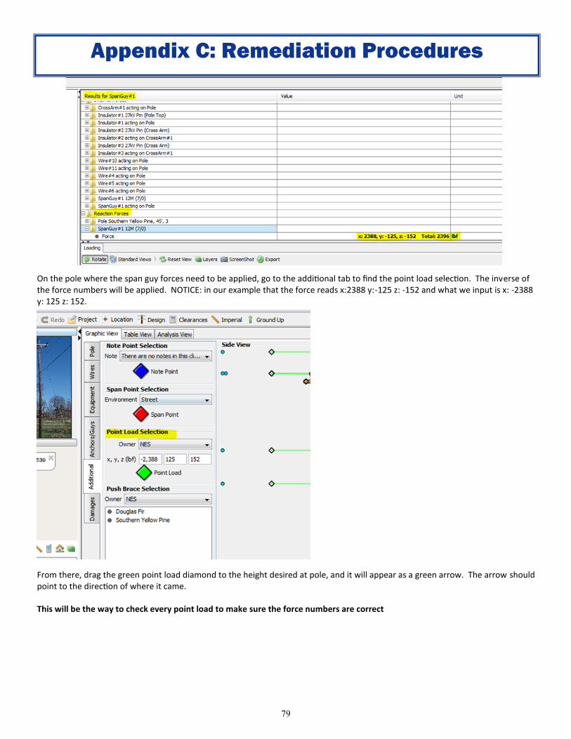
1.17 "Infrastructure" means NES distribution poles, transmission poles with distribution
underbuild, ducts, conduit, vaults, anchors, fiber optic cable capacity and active
communications capacity, facilities and all other utility infrastructure and associated
materials and equipment on or connected to these structures which are owned by, or
under the control of, NES.
1.18 "lnnerduct" means a flexible conduit installed by NES inside a larger conduit for the
placement of fiber optic cable.
1.19 "Joint-Use Agreement" means an agreement whereby each party in agreement owns poles
and has agreed that the other party has the right to attach to and occupy space upon the
poles owned by it.
1.20 "Joint User" means a joint user which may attach to a pole or anchor, or occupy conduit,
either solely or partially owned by NES, in return for granting NES equivalent rights of
attachment to poles and anchors and/or occupancy of conduit which it owns, either solely
or partially.
1.21 "License" means the written consent of NES for the operator to make its attachment.
1.22 "Make Ready" means all work that NES reasonably determines to be required to
accommodate the operator's attachments or those of another user, and/or to comply with
all applicable standards. Such work includes, but is not limited to, administrative work,
engineering work, rearrangement and/or transfer of NES facilities or existing attachments,
inspections, permitting work, tree trimming (other than tree trimming performed for
normal maintenance purposes), pole replacement and construction, or conduit system
clearing, but does not include the operator's routine maintenance.
B: Definitions
1. Introduction
Page 6
6
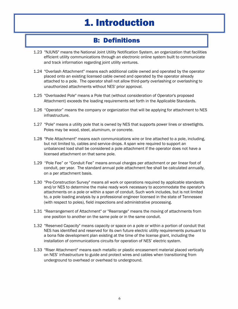
1.23 "NJUNS" means the National Joint Utility Notification System, an organization that facilities
efficient utility communications through an electronic online system built to communicate
and track information regarding joint utility ventures.
1.24 "Overlash Attachment" means each additional cable owned and operated by the operator
placed onto an existing licensed cable owned and operated by the operator already
attached to a pole. The operator shall not allow third-party overlashing or overlashing to
unauthorized attachments without NES' prior approval.
1.25 "Overloaded Pole" means a Pole that (without consideration of Operator's proposed
Attachment) exceeds the loading requirements set forth in the Applicable Standards.
1.26 “Operator” means the company or organization that will be applying for attachment to NES
infrastructure.
1.27 "Pole" means a utility pole that is owned by NES that supports power lines or streetlights.
Poles may be wood, steel, aluminum, or concrete.
1.28 "Pole Attachment" means each communications wire or line attached to a pole, including,
but not limited to, cables and service drops. A span wire required to support an
unbalanced load shall be considered a pole attachment if the operator does not have a
licensed attachment on that same pole.
1.29 “Pole Fee” or “Conduit Fee” means annual charges per attachment or per linear foot of
conduit, per year. The standard annual pole attachment fee shall be calculated annually,
on a per attachment basis.
1.30 "Pre-Construction Survey" means all work or operations required by applicable standards
and/or NES to determine the make ready work necessary to accommodate the operator's
attachments on a pole or within a span of conduit. Such work includes, but is not limited
to, a pole loading analysis by a professional engineer licensed in the state of Tennessee
(with respect to poles), field inspections and administrative processing.
1.31 "Rearrangement of Attachment" or "Rearrange" means the moving of attachments from
one position to another on the same pole or in the same conduit.
1.32 "Reserved Capacity" means capacity or space on a pole or within a portion of conduit that
NES has identified and reserved for its own future electric utility requirements pursuant to
a bona fide development plan existing at the time of the license grant, including the
installation of communications circuits for operation of NES’ electric system.
1.33 "Riser Attachment" means each metallic or plastic encasement material placed vertically
on NES’ infrastructure to guide and protect wires and cables when transitioning from
underground to overhead or overhead to underground.
B: Definitions
1. Introduction
Page 7
7
B: Definitions
1.34 “Safety Inspection” shall mean upon twelve (12) months advance written notice from
NES, and not more frequently than every five (5) years, NES may at its option jointly
perform a safety inspection in all or in part of the territory covered by this agreement with
all users to identify any safety violations of all attachments and facilities on or within NES
infrastructure. Such notice shall describe the scope of the inspection and provide the
operator and all users an opportunity to participate. The operator, NES and other users
shall share proportionately in the actual and documented safety inspection costs (based
on the proportion of attachments of NES and each other user) irrespective of whether
NES elects to perform the safety inspection itself or have it performed by a contractor.
1.35 "Service Drop" means a cable used to connect directly to a customer's location from one
pole and attached to no more than one additional pole where the additional pole does not
support voltage greater than six hundred volts (600V) or a cable used to connect a
customer's location through the use of multiple licensed poles where service drop make
ready has been performed.
1.36 “Supply Space” means the vertical portion of the structure that contains the electrical
supply facilities. Generally this space extends from the top of the structure to the lowest
point that the electrical supply facilities extend. The lowest point may be:
Bottom of a bracket
Bottom of a piece of equipment (i.e., Transformer, Sectionalizer, Recloser, Capacitor,
etc.)
Conductor
Top of a conduit riser for electrical supply conductors
NOTE: Under certain conditions street light conductors and hardware are excluded from
this list per NESC 238C.
1.37 “Transition Space” means the area located above the ground space and below the
communication space.
1.38 "Tag" means the placement of permanent identifying markers on attachments to make
the nature of the attachments and their ownership readily identifiable to NES and other
users. The acceptable methods for identifying communication cables are defined in this
document.
1.39 "Transfer of Attachments" or "Transfer" means the removing of attachments from one pole
and placing these onto another pole or moving of attachments from one location in NES'
conduit system to another location in NES' conduit system.
1.40 "Unauthorized Attachment" means any attachment placed on or within NES infrastructure
without authorization. An unauthorized attachment shall not include any attachment that
the operator is permitted to affix to a pole pursuant to their agreement with NES, even if
the installation of such attachment does not meet applicable standards or differs from
the design described in the applicable application.
1. Introduction
Page 8
8
B: Definitions
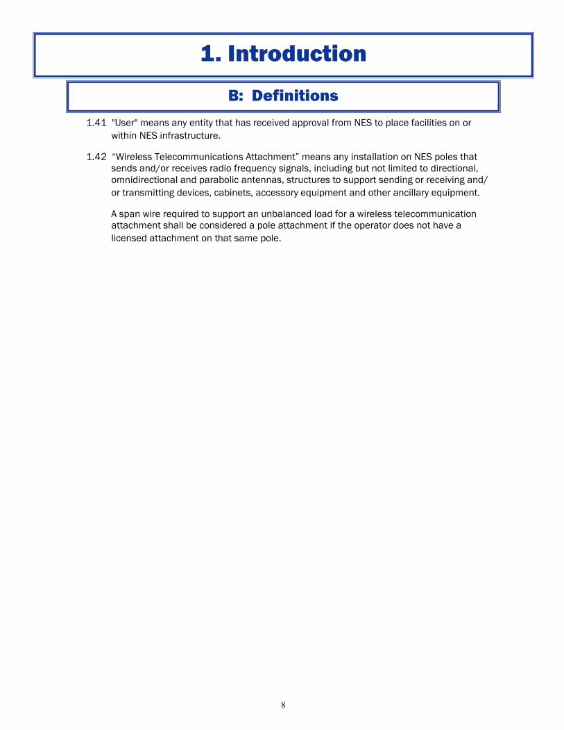
1.41 "User" means any entity that has received approval from NES to place facilities on or
within NES infrastructure.
1.42 “Wireless Telecommunications Attachment” means any installation on NES poles that
sends and/or receives radio frequency signals, including but not limited to directional,
omnidirectional and parabolic antennas, structures to support sending or receiving and/
or transmitting devices, cabinets, accessory equipment and other ancillary equipment.
A span wire required to support an unbalanced load for a wireless telecommunication
attachment shall be considered a pole attachment if the operator does not have a
licensed attachment on that same pole.
1. Introduction
Page 9
9
1. Enter Into Use Agreement: Prior to making attachments, the applicant must enter into an
Infrastructure Use Agreement (IUA) and apply for and obtain prior permission for the use of
each pole. To initiate this process, call 615-747-3970 or send an e-mail to
[email protected] . There will be a $750 initial set up fee invoiced to the applicant.
Once the fee is received, NES legal will send an agreement.
2. Obtain NJUNS Code: Prior to making attachments, the applicant shall obtain an NJUNS
member code. NJUNS is a national organization of member utilities formed for the purpose of
improving coordination for pole attachment transfers and other related issues. Go to
web.njuns.com to initiate the registration process. Users with less than fifty (50) attachments
are not required to have an NJUNS member code.
3. Submit Design Package: The applicant will be responsible for providing a design package
including the NES utility poles proposed for attachment. There is a limit of thirty (30) poles per
application
4. The applicant shall submit a proposal with the following:
Route Map
Attachment Construction Details
Pre-Construction survey files and results (optional, see appendices A & B)
Completed SPIDA®Calc file with necessary data (optional, see appendices A & B)
Construction drawing depicting adjustments to existing poles (optional, see appendices A &
B)
Compatible unit spreadsheet for power construction (optional, see appendices A & B)
Pole load analysis stamped by a Professional Engineer licensed in the state of Tennessee.
(optional, see appendices A & B)
5. Obtain Permits: Where attaching installations involve city, county and/or state road rights-of-
way or property owned by others such as Army Corp of Engineers, TVA or railroad companies,
NES strongly recommends the applicant contact (early in their planning process) the
appropriate authorities to obtain the necessary permit(s). The applicant will be required to
submit copies of the following permits (if required) before any license can be finalized:
Metro ROW and Road Crossing Permits:http://www.nashville.gov/Public-Works/
Permits.aspx
TDOT Permits: http://www.tdot.state.tn.us/environment/permits/waterquality.htm
US Army Corps of Engineer Permits: http://www.lrn.usace.army.mil/Missions/Regulatory/
ObtainaPermit.aspx
Railroad Crossing Permits: http://www.csx.com/fuseaction=about.property_corridor
TVA Crossing Permits: http://www.tva.com/river/26apermits/howto.htm
2. Basic Procedures
Page 10
10
6. Private Property Permission: At a minimum, applicants shall obtain written permission from all
private property owners when work related to the application results in anchors, poles,
attachments or other facilities will be located on or crossing private property.
7. Pay Fee: The operator shall be charged an application fee for each unit of NES infrastructure.
The application fee is due within forty five (45) days from receipt of invoice. At the time of this
publication the application is $65. NES reserves the right to revise the application fee at any
time to recover the actual costs incurred while processing applications.
8. Costs: Actual costs will be included in the Infrastructure Use Agreement. Reimbursements
shall include, but not necessarily be limited to, all design, engineering, administration,
supervision, payments, labor, overhead, materials, and equipment. Below is a list of additional
costs that may be occurred or are applicable.
Cable is charged based on each position on the pole.
Banners are charged based on the linear footage of the pole that is occupied.
Conduit usage is charged based on the linear footage.
Equipment charges vary based on the size and nature of the equipment.
Recurring Fees shall include a standard annual pole fee and an annual conduit rental fee.
Make Ready work and other associated costs.
Anchor Use Fees if allowed and agreed upon.
Penalties if necessary.
2. Basic Procedures
Page 11
11
2. Basic Procedures
A: Process Flow Chart
Page 12
12
A: Pole Attachment and Licensing Process
1. The Standard Pole Application and Licensing: The application process set out below shall be
followed.
1.1 Submission and Review of License Application: Operators shall submit their proposed
attachment through SPIDA®Min and the application shall contain the following:
A route map with each pole that the operator will be attaching
A list of materials that will be used for attaching
Operator’s construction standards
Required permits
Final OD for any overlashed spans with a final OD greater than two inches (2”).
1.2 When new Equipment Attachments are proposed, the operator is to provide construction
drawing/specs and build a mockup of any proposed equipment for engineering and
operations review.
1.3 If the operator's application does not include a pre-construction survey, NES shall review
the application and perform a pre-construction survey. If the attachment can be
accommodated, a description of any necessary make ready work will be prepared. NES will
respond to properly executed and complete permit application for routine installations as
promptly as is reasonable. NES’ response will either: (a) provide a description of make
ready and a cost estimate for the NES portion of that make ready; or (b) provide a written
explanation as to why the application is being denied.
1.4 Upon receipt of NES' make ready cost estimate, the operator shall have fourteen (14) days
to approve the estimate, and provide payment, if NES is going to perform the make ready.
1.5 All of the poles listed must be in close proximity to one another to be considered as part of
the same license application.
2. Make Ready Work: Once NES determines that the attachments can be accommodated
consistent with applicable standards, NES will either: (a) advise the operator that it agrees with
the operator's description and estimate of the kind of make ready necessary to accommodate
the attachments, including the need to rearrange and/or transfer attachments of other users,
or; (b) NES will prepare its own estimate of the kind of the make ready and explain the reasons
tor the difference; or (c) NES will recommend modifications to the operator's description and
estimate of the kind of make ready necessary to accommodate the attachments, including the
need to rearrange and/or transfer attachments of other users.
2.1 Make ready work in the electric supply space may be performed only by NES and/or a
qualified contractor authorized by NES to perform such work. NES may give operator the
option of either having NES perform any necessary make ready work, at the operator's cost,
3. License Application Process
Page 13
13
or allowing the operator to complete make ready work through the use of qualified
contractors authorized by NES.
2.2 If NES is to perform make ready work it will use good faith efforts to complete routine make
ready work within sixty (60) days of receipt of operator's approval of the make ready
estimate. If there are extenuating circumstances that make the necessary make ready
more complicated or time-consuming, including, but not limited to, the application
requesting attachment to more than one hundred (100) poles, or seasonal weather
conditions, NES shall identify those factors in the make ready description and cost estimate
and the parties shall agree upon a reasonable timeframe for completion
2.3 Upon completion of the make ready work performed by NES, NES shall invoice operator for
NES' actual and documented cost of such make ready work. The costs of the work shall be
itemized and if NES received advance payment, the costs shall be trued up. The operator
shall be responsible for entering into an agreement with existing other users to reimburse
them for any costs that they incur in rearranging or transferring their facilities to
accommodate the operator's attachments.
2.4 In performing all make ready work to accommodate operator's attachments, NES will
endeavor to include such work in its normal work schedule. If the operator requests, and
NES agrees, to perform make ready work on a priority basis or outside of NES' normal work
hours, the operator will pay any resulting increased actual and documented costs.
2.5 Before starting make ready work, NES shall notify all existing users of the date and location
of the scheduled work and notify them of the need to rearrange and/or transfer their
facilities at operator's cost within the specified time period, or NES will transfer its right to
the operator. To the extent that NES has the legal authority, it shall rearrange and/or
transfer existing facilities of such other users that have not been moved in a timely manner.
The operator shall pay for any such rearrangement or transfer
2.5 In instances where the operator is performing make ready, where an existing user has not
relocated or otherwise undertaken work required to complete make ready (such as
repairing existing attachments not in compliance with applicable standards) within thirty
(30) days of notice by NES or operator to such other user; the operator may be authorized,
to relocate or repair the other user's attachments on behalf of NES.
3. License as Authorization to Attach: Upon completion and inspection of any necessary make
ready work, NES will issue a license to the operator which shall serve as authorization for the
operator to make its attachments.
3.1 All of the operator's installation, removal, and maintenance work, by either the operator's
employees or authorized contractors, shall be performed at the operator's sole cost, in a
good and workmanlike manner, and shall not adversely affect the structural integrity of NES
infrastructure or other facilities or other users' facilities or equipment.
A: Pole Attachment and Licensing Process
3. License Application Process
Page 14
14
A: Pole Attachment and Licensing Process
3.2 The operator shall assure that any person installing, maintaining, or removing its facilities is
fully qualified and familiar with all applicable standards, including standards for working in
the supply space.
4. Notification of Make Ready Work Performed by NES: Before starting make ready work, NES
shall notify all applicable existing users of the date and location of the scheduled work and
notify them of the need to rearrange and/or transfer their facilities at the operator's cost, or
repair their facilities at such user's cost. The operator shall reimburse the owner or owners of
other facilities attached to NES poles for any actual and documented cost incurred by them for
rearranging or transferring such facilities, in order to accommodate the operator's attachments.
5. Repair: When an existing user has not undertaken work required to repair existing attachments
not in compliance with Applicable Standards within thirty (30) days of notice by NES or the
operator to such other user, the operator may be authorized, to repair the other user's
attachments on behalf of NES.
6. Payment for Make Ready Work: NES shall invoice the operator for NES' actual and documented
costs of such make ready work. The costs of the work shall be itemized and trued up. The
operator shall be responsible for entering into an agreement with existing attaching users to
reimburse them for any costs that they incur in rearranging or transferring their facilities to
accommodate the operator's attachments.
3. License Application Process
Page 15
15
1. NES or its contractors may perform a post-installation inspection for each attachment made to
NES infrastructure. Within thirty (30) days of written notice to NES that the operator has
completed installation of an attachment (including overlash, riser attachments, and/or service
drops), the operator shall pay the actual and documented costs for the post-installation
inspection.
1.1 lf NES elects to not perform any post-installation inspection, such non-inspection shall not
be grounds for any liability being imposed on NES or a waiver of any liability of operator.
1.2 NES will notify operator if the post-installation inspection reveals that the operator's facilities
have been installed in violation of applicable standards or the approved design. The
operator shall have thirty (30) days from the date of receipt of such notice to correct such
violations. NES may perform subsequent post installation inspections once the correction
has been made to ensure operator's attachments have been brought into compliance.
1.3 NES will provide notice of the continuing violation if the operator's attachments remain out
of compliance with applicable standards or approved design after any subsequent
inspection. The operator will have thirty (30) days from receipt of such notice to correct the
violation.
B: Post Installation Inspection
3. License Application Process
Page 16
16
1. Each user shall have a unique three digit code assigned to their cable. The user will be
assigned the three digit code by NES.
2. Cables shall be marked at the time of installation.
3. All tags shall:
Be secured so as to remain permanently affixed to the attaching company’s cable.
Be resistant to fading from the effects of weather, chemicals, etc.
Indicate the users three digit code in black characters on a yellow background. Have
characters no less than one inch (1”) and no greater than two inches (2”) in height.
Avoid the use of sharp edges and corners to prevent injury to personnel and damage to
cables.
Markers should be affixed at the point of attachment.
Multiple attachments on same pole shall be marked separately.
Have no information other than the three digit number assigned by NES. i.e.: Phone
number and/or company name are not acceptable.
Be located within two feet (2’) from a pole.
4. Please contact the NES Attachments Group for a listing of current markers and identifiers of
other companies attached on NES poles.
5. Cables should be tagged at the time of installation. Attaching companies should make tagging
an ongoing effort, and work toward complete tagging of all existing cables not previously
tagged.
6. It is the responsibility of the Operator to install tags such that the numbers are easily
identified from the ground.
C: Cable Identification
3. License Application Process
Page 17
17
1. The user should provide a plan with volume and expected turnaround time for the project.
2. The user and NES should agree on resources.
3. MOU with commitment to plan.
4. Allow eight (8) weeks to ramp up resources.
D: Expediting Large Projects
3. License Application Process
Page 18
18
The following procedures and requirements shall apply to the use of the conduit system.
1. Route Investigation/Survey: If the operator wishes to use a portion of NES conduit for
placement of its cables, the operator shall first request a Route Investigation/Survey to be
completed by NES. The Route Investigation/Survey shall be performed at operator's cost. Such
costs are to be actual and documented. Upon receipt and review of a Route Investigation/
Survey, the operator may apply for installation of its cable within the conduit system.
2. Conduit Usage License Application: The operator shall submit a properly executed Conduit
Usage License Application, which shall include detailed plans for the proposed attachments,
including:
A construction drawing indicating the location of and specifying the type of cable to be
installed.
All application requests shall be made through SPIDAMin
3. NES will review the application and discuss any issues with the operator, including engineering
or make ready work requirements associated with the Application.
4. NES shall review and respond to properly executed and complete Applications for routine
installations as promptly as is reasonable. NES’ response will either provide a written
explanation as to why the Application is being denied, or provide an estimate of the costs of all
necessary make ready work.
5. Upon receipt of NES' make ready estimate, the operator shall have fourteen (14) days to
approve the estimate and provide payment.
6. Upon receipt of payment of estimated make ready NES will begin routine make ready work
within the conduit and shall advise the operator of any extenuating circumstances that make
the necessary make ready more complicated or time-consuming.
7. Work Rules: NES will specify the type of construction required with respect to the conduit
system. NES will furnish to the operator written materials which will specify and explain the
required construction.
7.1 NES’ manholes or transformer vaults shall not be opened or tampered with by an
employee, agent or contractor of operator.
7.2 No employee, agent or contractor of the operator shall enter or work in any of NES’
manholes or transformer vaults without an authorized representative of NES present.
7.3 NES shall place, remove, change, and maintain all cable in the conduit system with
materials supplied by the operator. Once approved by NES and delivered to the location
designated by NES.
7.4 The operator's cable shall be permanently identified by tags (per the applicable standards)
at each manhole or other access opening in the conduit system. Tags shall be of a type
and wording reasonably satisfactory to NES, and consistent with NES guidelines. All cost of
this identification shall be the responsibility of operator.
4. Conduit Application and Use Requirements
A: General Requirements
Page 19
19
7.5 Where manholes or transformer vaults must be pumped in order to allow work operations
to proceed, pumping shall be done by NES at operator's cost, such cost to be actual and
documented.
7.6 Any leak detection liquid or device used by the operator or operator's agents, employees or
contractors shall be of a type approved in writing by NES.
7.7 No equipment or facilities other than cables are permitted within NES underground
structures. Slack loop and coils are not allowed within NES underground structures.
7.8 While work is performed around any part of NES' conduit system located in the streets,
alleys, highways, or other public rights-of-way or easements granted to NES or City of
Nashville, the protection of persons and property shall be provided by the operator. The
operator shall be solely responsible for providing adequate barricades, warning lights,
traffic cones, danger signs, and other similar devices to protect all traffic, persons, and
property around the work area from danger. The operator shall be required to provide
uniformed police during construction or installation in any areas of the City of Nashville
where NES is required.
7.9 NES' authorized representative shall have the authority to terminate operator's work
operations around NES’ manholes or transformer vaults if any hazardous condition arises
or any unsafe practice is being followed by operator's agents, employees or contractors.
7.10 The operator further agrees to comply with all safety laws, regulations, ordinances, and
statutes pertaining to the work to be performed and the tools and equipment used to
accomplish such work, bear the solely responsible for the compliance therewith by its
employees, agents, servants and/or contractors.
8. Conduit Attachment Procedures
8.1 All installations in conduits must be approved and performed by NES. The operator shall
reimburse NES for all actual and documented costs incurred.
8.2 The operator's representative shall be present during all NES installation of underground
cable, innerduct, splice capsules and accessories. The operator's representative shall be
knowledgeable and experienced in underground cable, innerduct, splice capsules and
accessory installation and shall be authorized by the operator to answer questions and
make decisions on the operator's behalf regarding problems and questions that occur
during NES installation of underground cable, innerduct, splice capsules and accessories.
The operator's representative shall be furnished at operator's cost. NES will maintain
ownership of the unused innerduct cells for future use.
8.3 NES may reserve conduit and ducts for its core electric service. NES may pull a cable into
any of NES' conduits either occupied by or scheduled to be occupied by operator's facilities.
Should it become necessary for NES to use a conduit occupied by the operator. The
operator's cable may upon notice be removed by NES. The operator may request NES to
expand conduit or duct capacity, at the cost of the operator.
A: General Requirements
4. Conduit Application and Use Requirements
Page 20
20
8.4 The operator shall compensate NES for the actual and documented cost, including
engineering and administrative cost, for the connection of the operator's conduit which
connects to NES’ manhole or transformer vault. The section of connecting conduit shall
not be longer than five feet (5’) and shall be maintained by NES at the operator's cost.
8.5 The operator shall compensate NES for the actual and documented cost, including
engineering and administrative cost, for any work required to make a conduit usable for
the initial placing of the operator's cable and/or innerduct.
8.6 NES may rearrange the operator's cable at the cost of the operator when necessary to
make maximum use of its conduit system. The cost to will be the actual and documented.
9. Emergency Circumstances
9.1 NES’ work shall take precedence over any and all operations of the operator.
9.2 The operator is responsible for supplying to NES a points of contact for non-emergency and
emergency twenty four (24) hour service and for informing NES of any change in points of
contact.
9.3 In the event the operator experiences an emergency with its attachments located in NES’
conduit system, an NES representative shall be at the site before the operator enters a
manhole and/or works on the cable in NES’ conduit system for any reason. NES will
respond to an emergency as arranged between the operator and an NES representative.
An emergency call associated with the operator or NES’ customers out of service will be
treated on a "priority" basis. NES' response time will be based on the situation existing at
the time of the emergency. All NES labor and material associated with any operator
emergency that does not arise from faults in the conduit system or the acts or omissions of
any other user of the conduit system will be billed to the operator.
A: General Requirements
4. Conduit Application and Use Requirements
Page 21
21
NES distribution poles are part of an overhead electrical distribution system. The power lines
attached to these poles should always be presumed energized. All persons, including the
operator’s employees and contractors must exercise caution and take all reasonable precautions
when working on or near electric utility poles, and/or near high voltage lines. NES employees and
contractors are specially trained to perform their jobs safely by adhering to OSHA safety
requirements.
1. Prior to proceeding with their physical installations on NES poles, operators should ensure their
workers (whether employees or contractors) are qualified to work on NES poles or near NES
electrical lines.
2. At all times during their construction activities on NES poles, operators should adhere to the
following:
When installing or maintaining its facilities, the operator’s construction crews, whether
employees or contractors, must be able to show some form of written interim
permission covering the specific construction.
Communication cables must be properly guyed and anchored before tensioning. This
means the operator must install separate guying and anchoring devices to secure their
cables.
On existing steel or concrete poles, use existing holes or banding. No new holes should
be drilled.
NOTE: The operator is responsible for the costs of any damage to NES facilities resulting
from improper guying, anchoring, and/or loading.
3. New wireline attachments should typically overbuild existing wireline attachments, while
satisfying all applicable standards.
4. Pole Replacements: At the operator’s request, an existing pole may be replaced with a taller or
stronger pole in order to accommodate an attachment. The operator shall pay the actual and
documented cost of the pole replacement including but not limited to all labor and
material. NES will replace a pole that is determined to be defective or overloaded (without
consideration of operator’s proposed attachment), provided the communications space on the
existing pole could have been arranged with sufficient spacing to accommodate the operator's
proposed attachments . Primary riser poles and gang-operated switch poles shall always be
replaced with a steel pole. In all cases the associated materials and equipment, including but
not limited to crossarms, cut-outs, insulators, and minor materials such as nuts, bolts, washers,
etc., shall be replaced and considered part of the pole replacement.
5. Equipment Attachments: The operator shall compensate NES for the actual and documented
cost, including engineering and administrative cost, for rearranging, transferring, and/or
relocating NES infrastructure to accommodate operator's equipment attachments. The
operator shall reimburse the owner or owners of other facilities attached to NES infrastructure
for any actual and documented cost incurred by them for rearranging or transferring such
facilities to accommodate the operator's equipment attachments.
6. Authorized Contractors: The operator shall only use authorized, qualified contractors approved
by NES to conduct make ready work (or any other work) in or around the electric supply space
on a pole.
5. Construction Guidelines
Page 22
22
7. Guys and Anchor Attachments: The operator shall place guys and anchors to sustain any unbalanced
loads caused by operator's attachments. Under unusual circumstances NES may allow the operator to
attach its guys to anchors owned by NES. The operator will be charged a one-time anchor fee. NES will
notify operator of the changes necessary to provide an adequate anchor or guy. The operator will
compensate NES for the actual and documented cost including engineering and administrative cost for
changing the guy and anchor.
New anchors six inches (6”) diameter or less should be set at minimum three feet (3’) from
existing NES power and NES communication anchors. Manta Ray driven anchors are included in
the less than six inch (6”) category.
Anchors larger than six inches (6”) should be placed five feet (5’) from NES power anchors and
three feet (3’) from NES communication anchors.
The installing anchor should be installed a few degrees away from existing to ensure proper
spacing at installed depth.
No anchor shall be installed closer than four feet (4’) from a pole.
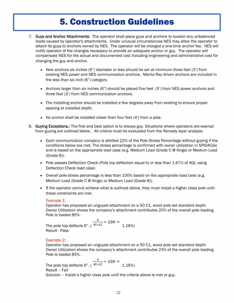
8. Guying Exceptions.: The first and best option is to always guy. Situations where operators are exempt
from guying are outlined below. All criteria must be evaluated from the Remedy layer analysis.
Each communication company is allotted 22% of the Pole Stress Percentage without guying if the
conditions below are met. The stress percentage is confirmed with owner utilization in SPIDACalc
and is based on the appropriate load case (e.g. Medium Load (Grade C @ Xings) or Medium Load
(Grade B)).
Pole passes Deflection Check (Pole top deflection equal to or less than 1.67% of AGL using
Deflection Check load case)
Overall pole stress percentage is less than 100% based on the appropriate load case (e.g.
Medium Load (Grade C @ Xings) or Medium Load (Grade B)).
If the operator cannot achieve what is outlined above, they must install a higher class pole until
these constraints are met.
Example 1:
Operator has proposed an unguyed attachment on a 50 C1, wood pole set standard depth.
Owner Utilization shows the company’s attachment contributes 20% of the overall pole loading.
Pole is loaded 85%.
The pole top deflects 6”. ( 1.16%)
Result - Pass
Example 2:
Operator has proposed an unguyed attachment on a 50 C1, wood pole set standard depth.
Owner Utilization shows the company’s attachment contributes 23% of the overall pole loading.
Pole is loaded 85%.
The pole top deflects 6”. ( 1.16%)
Result – Fail
Solution – Install a higher class pole until the criteria above is met or guy.
5. Construction Guidelines
Page 23
23
5. Construction Guidelines
Example 3:
Operator has proposed an unguyed attachment on a 50 C1, wood pole set standard depth.
Owner Utilization shows the company’s attachment contributes 5% of the overall pole loading.
Pole is loaded 85%.
The pole top deflects 9.3”. ( 1.8%)
Result – Fail
Solution – Install a higher class pole until the criteria above is met or guy .
9. Grounding and connections of the operator’s equipment to NES’ neutral system will be made for the
documented costs at the operators expense. All grounds installed by the operator shall be in
accordance with NES’ standards.
10. Service drops between poles must be bundled.
11. Upon completion of construction, the licensee must notify NES by e-mail ([email protected] )
or telephone (615-747-3970). Any existing codes violations should be brought to NES’ attention at this
time.
12. Refer to the most recent edition of the NESC; including but not limited to, Part 4 Work Rules for the
Operation of Electric Supply and Communication Lines and Equipment; Section 41 - Supply and
Communication systems - Rules for Employers; Subsection 411E - Identification and Location.
13. Banners may be permitted on decorative street light poles, but may require additional approvals and
shall meet the following conditions.
Banner installations and their content shall be approved by the owner of the property in which
the pole is located.
All banner arms shall be of the breakaway type.
Banners shall not be permitted in the power supply space.
13. Christmas decorations may be permitted on decorative streetlight poles but may require additional
approval and shall meet the following conditions.
Christmas decorations shall have the approval of the owner of the property in which the pole
is located.
Powered Christmas decorations shall follow the same process as other powered equipment.
Page 24
24
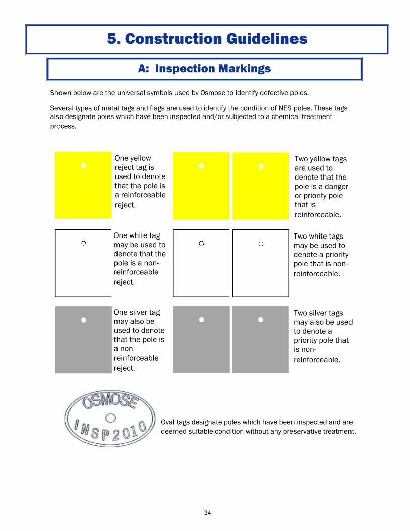
Shown below are the universal symbols used by Osmose to identify defective poles.
Several types of metal tags and flags are used to identify the condition of NES poles. These tags
also designate poles which have been inspected and/or subjected to a chemical treatment
process.
Oval tags designate poles which have been inspected and are
deemed suitable condition without any preservative treatment.
A: Inspection Markings
One yellow
reject tag is
used to denote
that the pole is
a reinforceable
reject.
Two yellow tags
are used to
denote that the
pole is a danger
or priority pole
that is
reinforceable.
One white tag
may be used to
denote that the
pole is a non-
reinforceable
reject.
Two white tags
may be used to
denote a priority
pole that is non-
reinforceable.
One silver tag
may also be
used to denote
that the pole is
a non-
reinforceable
reject.
Two silver tags
may also be used
to denote a
priority pole that
is non-
reinforceable.
5. Construction Guidelines
Page 25
25
B: Utility Operator Basics
Supply Space
Communication Worker Safety Zone
Communications Space
Transition Space
Ground Space
Support Space
5. Construction Guidelines
Page 26
26
C: Identifying NES Cables
SERVICE DROP
5. Construction Guidelines
Page 27
27
D: Communication Line Clearance Requirements
5. Construction Guidelines
1. NES’ requirements for vertical clearances of wires, conductors, and cables are based NESC Rule 232. It is
the responsibility of the owner to ensure that all installations meet or exceed the requirements listed in the
NESC. In some situations NES requirements will exceed the NESC requirements. All NES Minimum clearance
requirements are based on worst-case sag conditions. Note that weather conditions can cause significant
changes in sag.
Acknowledging that enforcing worst-case sag can be difficult, NES has established the following standard to
assist Attachers in remediation of clearance issues on NES owned poles.
NES objective is for Field Measured Minimum ground clearance to be one foot — six inches (1’-6”) greater
than the NES Minimum.
2. NES shall not allow installation of new facilities or lowering of existing facilities below this Field Measured
Minimum.
3. Existing facilities that are discovered to be less than NES Minimum shall be brought up to Field Measured
Minimum during remediation unless sag charts are provided to confirm that the remediated facility complies
with NES Minimum clearances.
4. Existing facilities will be allowed to remain below the Field Measured Minimum with the understanding that it
is the responsibility of the existing facility owner to ensure that all installations meet or exceed the NES
Minimum.
5. Again, weather conditions can cause significant changes in sag. Ice loading typically results in worst-case sag.
NES does not expect that Attachers will be remediating existing or installing new facilities to this Field
Measured Minimum when ice is present on the line. In all cases, it is the responsibility of the attachment
owner to ensure that all installations meet or exceed the NES Minimum.
Page 28
28
D: Communication Line Clearance Requirements
5. Construction Guidelines
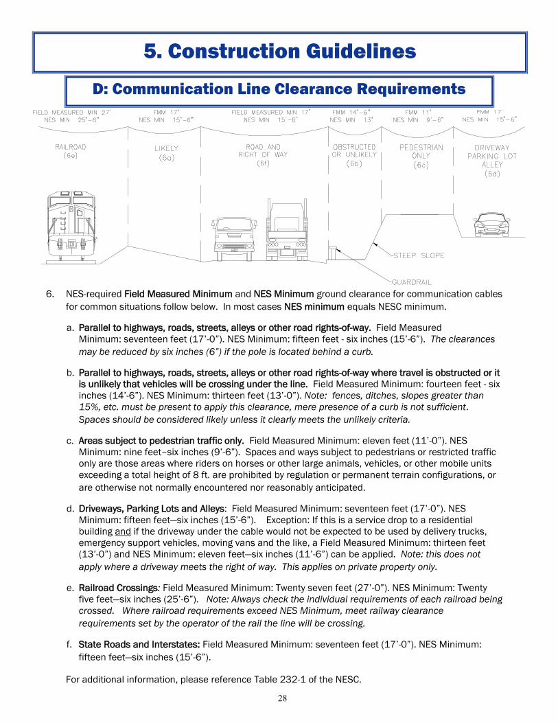
6. NES-required Field Measured Minimum and NES Minimum ground clearance for communication cables
for common situations follow below. In most cases NES minimum equals NESC minimum.
a. Parallel to highways, roads, streets, alleys or other road rights-of-way. Field Measured
Minimum: seventeen feet (17’-0”). NES Minimum: fifteen feet - six inches (15’-6”). The clearances
may be reduced by six inches (6”) if the pole is located behind a curb.
b. Parallel to highways, roads, streets, alleys or other road rights-of-way where travel is obstructed or it
is unlikely that vehicles will be crossing under the line. Field Measured Minimum: fourteen feet - six
inches (14’-6”). NES Minimum: thirteen feet (13’-0”). Note: fences, ditches, slopes greater than
15%, etc. must be present to apply this clearance, mere presence of a curb is not sufficient.
Spaces should be considered likely unless it clearly meets the unlikely criteria.
c. Areas subject to pedestrian traffic only. Field Measured Minimum: eleven feet (11’-0”). NES
Minimum: nine feet–six inches (9’-6”). Spaces and ways subject to pedestrians or restricted traffic
only are those areas where riders on horses or other large animals, vehicles, or other mobile units
exceeding a total height of 8 ft. are prohibited by regulation or permanent terrain configurations, or
are otherwise not normally encountered nor reasonably anticipated.
d. Driveways, Parking Lots and Alleys: Field Measured Minimum: seventeen feet (17’-0”). NES
Minimum: fifteen feet—six inches (15’-6”). Exception: If this is a service drop to a residential
building and if the driveway under the cable would not be expected to be used by delivery trucks,
emergency support vehicles, moving vans and the like, a Field Measured Minimum: thirteen feet
(13’-0”) and NES Minimum: eleven feet—six inches (11’-6”) can be applied. Note: this does not
apply where a driveway meets the right of way. This applies on private property only.
e. Railroad Crossings: Field Measured Minimum: Twenty seven feet (27’-0”). NES Minimum: Twenty
five feet—six inches (25’-6”). Note: Always check the individual requirements of each railroad being
crossed. Where railroad requirements exceed NES Minimum, meet railway clearance
requirements set by the operator of the rail the line will be crossing.
f. State Roads and Interstates: Field Measured Minimum: seventeen feet (17’-0”). NES Minimum:
fifteen feet—six inches (15’-6”).
For additional information, please reference Table 232-1 of the NESC.
Page 29
29
E: Attachment Clearance Requirements
5. Construction Guidelines
12" MIN
12" MIN
12" MIN
12" MIN
12" MIN TO DRIP LOOPFOR GROUNDED MAST ARMS AND GROUNDED SPAN WIRE CARRYING
LIGHTS, TRAFFIC SIGNALS OR BANNERS.20" IF UNGROUNDED, SEE NESC 238-2.
6"CATV POWER SUPPLY CONDUIT/ WEATHERHEADCATV DRIP LOOP
COMMUNICATION LINES ANDMINIMAL VOLTAGE PUBLIC WORKSSIGNALS, IN NO PARTICULAR ORDER
ARM MOUNTED TRAFFIC SIGNALS18' DESIRED HEIGHT
16'-6" MIN21' MAX
15 MPH
SCHOOL ZONE
40" COMMUNICATION WORKER SAFETY ZONE(NESC TABLES 235-5 AND 238-1)
3W SECONDARY RACK OR SPOOL INSULATOR
Page 30
30
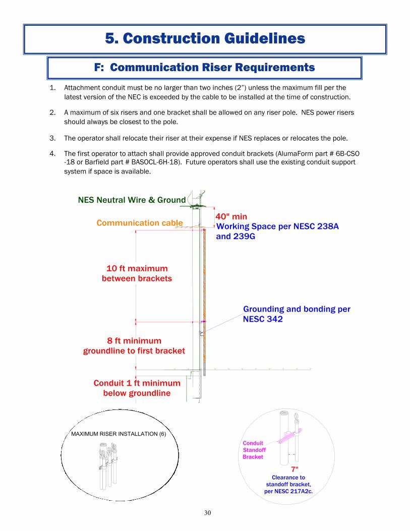
F: Communication Riser Requirements
1. Attachment conduit must be no larger than two inches (2”) unless the maximum fill per the
latest version of the NEC is exceeded by the cable to be installed at the time of construction.
2. A maximum of six risers and one bracket shall be allowed on any riser pole. NES power risers
should always be closest to the pole.
3. The operator shall relocate their riser at their expense if NES replaces or relocates the pole.
4. The first operator to attach shall provide approved conduit brackets (AlumaForm part # 6B-CSO
-18 or Barfield part # BASOCL-6H-18). Future operators shall use the existing conduit support
system if space is available.
NES Neutral Wire & Ground
8 ft minimum
groundline to first bracket
40" min
Conduit
Standoff
Bracket
7.5"
Maximum of
three (3) risersper pole
Conduit 1 ft minimum
below groundline
10 ft maximum
between brackets
Clearance to
standoff bracket,
per NESC 217A2c.
Communication cable Working Space per NESC 238A
and 239G
Grounding and bonding per
NESC 342
MAXIMUM RISER INSTALLATION (6)
Clearance to
standoff bracket,
per NESC 217A2c.
Conduit
StandoffBracket
7"
5. Construction Guidelines
Page 31
31
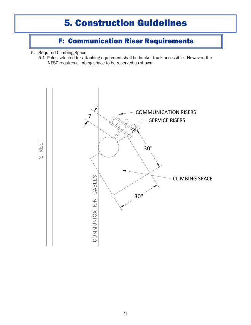
5. Required Climbing Space
5.1 Poles selected for attaching equipment shall be bucket truck accessible. However, the
NESC requires climbing space to be reserved as shown.
F: Communication Riser Requirements
5. Construction Guidelines
30"
CLIMBING SPACE
7"COMMUNICATION RISERS
SERVICE RISERS
30"
Page 32
32
6. Treatment of Poles with Existing Riser Installations
6.1 Existing Pole not being replaced.
If six (6) or more risers (including conduit and cables not installed in conduit) are present,
additional communication risers cannot be added. Reconfiguration of existing risers is not
expected.
6.1.1 Existing Communication Only Risers
If less than six (6) risers (including conduit and cables not installed in conduit) are
present, new riser conduit(s) may be installed only in a new or existing standoff
bracket, up to a total of six (6) (including existing conduits).
6.1.2 Existing NES Power Only Risers
If less than six (6) riser conduits are present, new riser conduit(s) may be installed
only in a new or existing standoff bracket, up to a total of six (6) (including existing
conduits).
6.1.3 Existing Communication and NES Power Risers
If less than six (6) riser conduits are present, new riser conduit(s) may be installed
only in a new or existing standoff bracket, up to a total of six (6) (including existing
conduits).
6.2 Existing Pole is to be Replaced
If six (6) or more risers (including conduit and cables not installed in conduit) are present,
additional communication risers cannot be added. The owners of existing risers shall
transfer to the new pole and comply as closely as possible with the standards.
6.2.1 Existing Communication Only Risers
If less than six (6) risers (including conduit and cables not installed in conduit) are
present, new riser conduit(s) may be installed in a new standoff bracket, up to a total
of six (6) (including existing conduits). Existing communication risers shall transfer to
the new bracket.
The new pole shall be installed in a location as close as practical to a majority of the
existing risers.
6.2.2 Existing NES Power Only Risers
If less than six (6) riser conduits are present, new riser conduit(s) may be installed in
a new standoff bracket, up to a total of six (6) (including existing conduits) after
existing NES power risers are transferred to the new bracket.
The new pole shall be installed in a location as close as practical to a majority of the
existing risers.
6.2.3 Existing Communication and NES Power Risers
If less than six (6) riser conduits are present, new riser conduit(s) may be installed in
a new standoff bracket, up to a total of six (6) (including existing conduits) after
existing NES power risers are transferred to the new bracket.
The new pole shall be installed in a location as close as practical to the existing NES
Power risers.
F: Communication Riser Requirements
5. Construction Guidelines
Page 33
33
1. Scope
This section establishes the requirements for installation of non-traditional equipment and
commonly known as “equipment attachments” on Nashville Electric Service (NES) structures.
2. Approval
2.1 Installation of non-wireless equipment requires notification to NES within 30 days of
installation.
2.2 Antenna equipment shall be approved on a pole-by-pole basis.
3. Operation and Maintenance
3.1 Equipment attachments shall not restrict the operation or maintenance of the power
distribution system equipment.
3.2 All equipment attachments that are located within the supply space shall be installed,
repaired, modified, and removed by qualified electrical workers who are employed by NES
or its approved contractors.
3.3 Cabinets should be used to house equipment. The maximum envelope of the cabinet can
be no larger than 70”H x 24”W x 24”D. The mounting must meet one of these three
conditions.
If the cabinet measures 6”H x 12”W x 4”D or smaller it may be direct mounted to the
pole.
Cabinets up to 70”H x 24”W x 24”D may be directed mounted to the pole if the pole is
located within 15’ of a bucket truck accessible paved road.
Cabinets up to 70”H x 24”W x 24”D not located within 15’ of a bucket truck accessible
paved road, must be mounted on a standoff bracket that does not interfere with NES
fall arrest equipment. That bracket and the cabinet must still fall inside that 24” depth
measurement.
4. Labeling
4.1 All equipment cabinets, boxes, and enclosures shall be clearly marked with:
The equipment owner’s name.
A 24-hour contact phone number.
Alpha/numeric designation such that the owner can determine the equipment location,
type and function.
NES-assigned three (3) digit code.
G: Equipment Attachments
5. Construction Guidelines
Page 34
34
5. Suitable Poles
5.1 Existing equipment that would exclude a pole is listed but not limited to the following:
Three phase gang-operated switches or three phase transformer bank
Capacitor Banks, reclosers
Distribution lines in more than two directions
Poles with existing cabinets and/or wireless equipment including but not limited to
power equipment controls, traffic controls, antennas and communications/CATV
equipment
5.2 All antenna installations may be made on poles that are located within 15’ of a bucket
truck accessible paved road.
5.3 Decorative Light Poles shall be approved on a case by case basis.
6. Suitable Locations for Antenna Equipment
6.1 Where installation of antenna equipment is requested, installation said facilities shall not
be allowed within the in the communication space or communication worker safety zone.
6.2 Antenna facilities will generally be installed on the top of the distribution pole. It shall be
the sole discretion of NES as to the location of the antenna facilities on NES owned poles.
7. Emergency Electrical Supply
7.1 Generators or other means of emergency electrical supply to communication cable
facilities are prohibited unless specifically approved by NES Engineering. Any generation or
back-up power supply shall not be interconnected with the NES electrical system.
G: Equipment Attachments
5. Construction Guidelines
Page 35
35
Notes:
1. Supply conduit cannot go through
equipment cabinet and must run
directly to the meter base.
2. Meter base to be provided by
communications company.
2. Meter shall be mounted 5’-6” from
ground.
3. Meter shall not face the street, alley,
or property side of the pole.
4. Meter base and disconnect shall be
bonded to a separate ground from the
pole ground with conductor having a
current capacity than no less than #6
solid copper conductor.
5. Conduit not to exceed 2” in diameter
without approval.
6. Conduit may be mounted directly to
the pole or u-guard may be used if the
pole is within 15’ of a bucket truck
accessible paved road. If not
accessible and the conduit is greater
than 1 1/2”, the conduit is to be
mounted with a standoff bracket that
provides 7” clearance from the pole to
the conduit.
7. Meter Base to be a single position,
ring-style, single phase, 4 terminal
100/125 amp overhead/underground
meter base unless it is fed from a
three phase transformer. If fed from
three phase it will require a fifth
terminal kit.
8. Meter base to be mounted to pole
using a Barfield Pole Mounting
Bracket # BAPMBL
9. Service will be provided at 120/240 V
(not just 120V).
10. A “DANGER DO NOT CLIMB” sign
should be securely attached at eye
level on the pole.
11. Equipment cannot overhand the
roadway.
12. The customer disconnect can not be
locked.
8. Communication Power Supply Riser
G: Equipment Attachments
5. Construction Guidelines
Communication WorkerSafety Zone 40" Min.
Customer-ProvidedMeter Base
5'-6"
Customer-ProvidedDisconnect If Requiredby Codes Or NES
CommunicationEquipment Cabinet(See EquipmentAttachments 3.3)
Communication Riser
2' BelowLowest Comm.
Max 20'
Page 36
36
9. Communication Power Supply Riser on a street light or secondary only pole
G: Equipment Attachments
5. Construction Guidelines
Notes:
1. All notes from 8. Communication Power Supply (previous page) still apply.
2. Equipment attachments on decorative and foundation poles will be considered on a case-by-case
basis.
Communication Riser
Power Riser
40" Min.
Page 37
37
10. Suitable Locations for Antenna Equipment Mounted to Poles
Equipment Mounted Above Primary Circuits
Notes:
1. The equipment owner shall educate the electrical workers prior to the start of work in the supply space such
that the workers understand the hazards of working around the equipment. The electrical workers shall be
knowledgeable of, and trained in methods necessary to monitor and mitigate the hazards associated with the
equipment.
2. Antennas that have a maximum permissible exposure that exceeds the FCC limits for General Population/
Uncontrolled Exposure, given in the FCC’s rules shall have a disconnect located within the ground space.
3. Under certain conditions wireless equipment will be allowed within the power space. Permission to locate
equipment within the power space will be determined on a case by case basis.
4. Conduit not to exceed 2” in diameter without approval.
5. Conduit 1 1/2” in diameter or less may be direct mounted to pole. If more than two 1 1/2” or less diameter
conduits are required, they must all be mounted in an approved standoff bracket. Conduits with a diameter
greater than 1 1/2” are to be mounted with a standoff bracket that provides 7” clearance from the pole to the
conduit.
6. Only one wireless communication attachment shall be allowed per pole.
7. The antenna size, configuration, mounting arrangement, location on the pole and other parameters may be
approved on an case-by-case basis.
G: Equipment Attachments
5. Construction Guidelines
Antenna Equipment
50" Min. From Drip Loop
or Antenna
RF Warning Sign
Page 38
38
11. Clearances for pad mounted equipment
Note: Refer to the NES Electric Service Guidelines for ditch details.
G: Equipment Attachments
5. Construction Guidelines
Min 36"Communication Lines
Min 10.0'
Secondary SupplyCommunications
RF Warning Sign
Lockable
Disconnect
Customer-Provided
Meter Base
Page 39
39
Note: Refer to the NES Electric Service Guidelines for ditch details.
12. Typical Customer-Owned Stub Pole for Communications Provider
G: Equipment Attachments
5. Construction Guidelines
Min 10'
40" Min.
Customer-Provided
Meter Base
Hand Hole
RF Emergency Power
Shut-Off Switch
Min 6'
RF Warning Sign
RF Warning Sign 72" Min.
120V-600V Service
Page 40
40
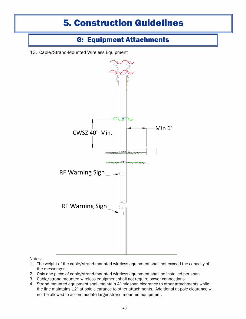
13. Cable/Strand-Mounted Wireless Equipment
Notes:
1. The weight of the cable/strand-mounted wireless equipment shall not exceed the capacity of
the messenger.
2. Only one piece of cable/strand-mounted wireless equipment shall be installed per span.
3. Cable/strand-mounted wireless equipment shall not require power connections.
4. Strand mounted equipment shall maintain 4” midspan clearance to other attachments while
the line maintains 12” at pole clearance to other attachments. Additional at-pole clearance will
not be allowed to accommodate larger strand mounted equipment.
G: Equipment Attachments
5. Construction Guidelines
RF Warning Sign
RF Warning Sign
CWSZ 40" Min.Min 6'
Page 41
41
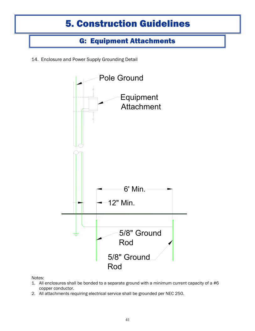
14. Enclosure and Power Supply Grounding Detail
Notes:
1. All enclosures shall be bonded to a separate ground with a minimum current capacity of a #6
copper conductor.
2. All attachments requiring electrical service shall be grounded per NEC 250.
G: Equipment Attachments
5. Construction Guidelines
Equipment
Attachment
Pole Ground
12" Min.
6' Min.
5/8" Ground
Rod
5/8" Ground
Rod
Page 42
42
Any time work is performed, notification should be given if lashed bundle is under 2” and a new
Application submitted if over 2”. This applies even for emergency replacements to give NES the
opportunity to inspect the work.
Method of Replacing Existing Facilities (depending time to complete)
< 30 days (<14 days preferred) – delash old, place old in rollers (secure and taunt),
lash new, cutover, remove old
> 30 days but <120 days – place old on temporary 12-14” standoff (provide
construction standard and standoff spec), install new in old position, cutover,
remove old and standoff
> 120 days – apply for new position, apply to remove old position
H: System Maintenance
5. Construction Guidelines
Page 43
43
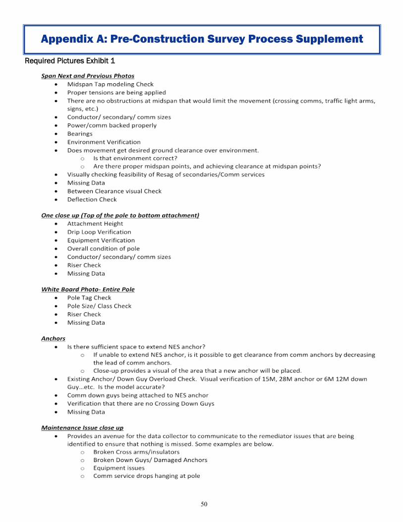
Appendix A: Pre-Construction Survey Process Supplement
Pole data and results shall be properly entered and modeled in a SPIDA®Calc file. As a part of the survey,
the operator will take field measurements entered into SPIDA®Calc to determine National Electrical Safety
Code (NESC) clearance requirements and wind and ice loading calculations to determine the structural
capacity of the pole. The SPIDA®Calc file will consist of narrative and pictures. The construction drawing
will serve as a guide for the installation of pole attachments and will include the operators attachment
height with any make ready recommendations necessary to prepare the pole for attachments.
SPIDA®Calc Required Design Layers:
Existing
Proposed
Remedy
Construction Drawings:
Refer to the Construction Drawing Standards section in the Nashville Electric Service Construction Plate
Book.
Page 44
44
Compatible Unit Spreadsheet
Proposal Submittal-SPIDA®Min:
1. Log into SPIDA®Min.
2. Select desired poles on the map.
3. Select Action, Create Project and choose desired workflow.
Appendix A: Pre-Construction Survey Process Supplement
APPLICATION - NAME
Date 4/28/2015
Prepared by [Operator]
CPR LOC. 10-Urban Services Item Pole No. X, Y
(State
Plane)
MR or
MNT Removal
Equipment
Type
Removal
Equipment Qty. Removal
Cost New
Equipment
Type
New
Equipment Quantity Install
Cost
1 123-45-678 MR Wood Pole RO-PW35-45 1 Wood
Pole OPW50-C1 1
1 123-45-678 MR 1 XARM OXW10 2
2 123-45-678 MNT Steel Pole RO-PW50-60 1 Steel Pole OP555-H1 1
2 123-45-678 MNT 1 XARM OSX10 1
Page 45
45
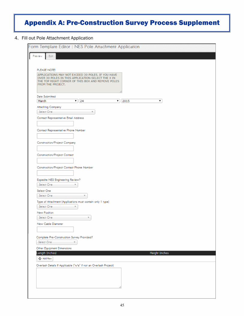
4. Fill out Pole Attachment Application
Appendix A: Pre-Construction Survey Process Supplement
Page 46
46
5. After the above form is completed, the project will land in a status and acquire the "Preconstruction
Survey Form" seen below. This form lists the items that are required to be uploaded in order for the
project to contain a complete preconstruction survey. The operator is to include these items and select
Yes in the "All of the above uploaded to the Files section?" field.
6. In the Forms section, fill out the "Initial Invoicing" form seen below. The "Application Fee" field will auto-
populate with the application fee for the project (based on # of poles in the project), and the Poles
table will auto-populate with all of the poles in the
application.
Appendix A: Pre-Construction Survey Process Supplement
Page 47
47
7. Finally, if Yes was selected in the "Expedite NES Engineering Review?" core form field, the project will
pick up the form below. The Estimated Charges fields will auto-populate with the charges (based on #
of poles in the project). Select yes or no in the drop down.
8. Once these forms are completed, the project will advance to Submit Application to NES.
Appendix A: Pre-Construction Survey Process Supplement
Page 48
48
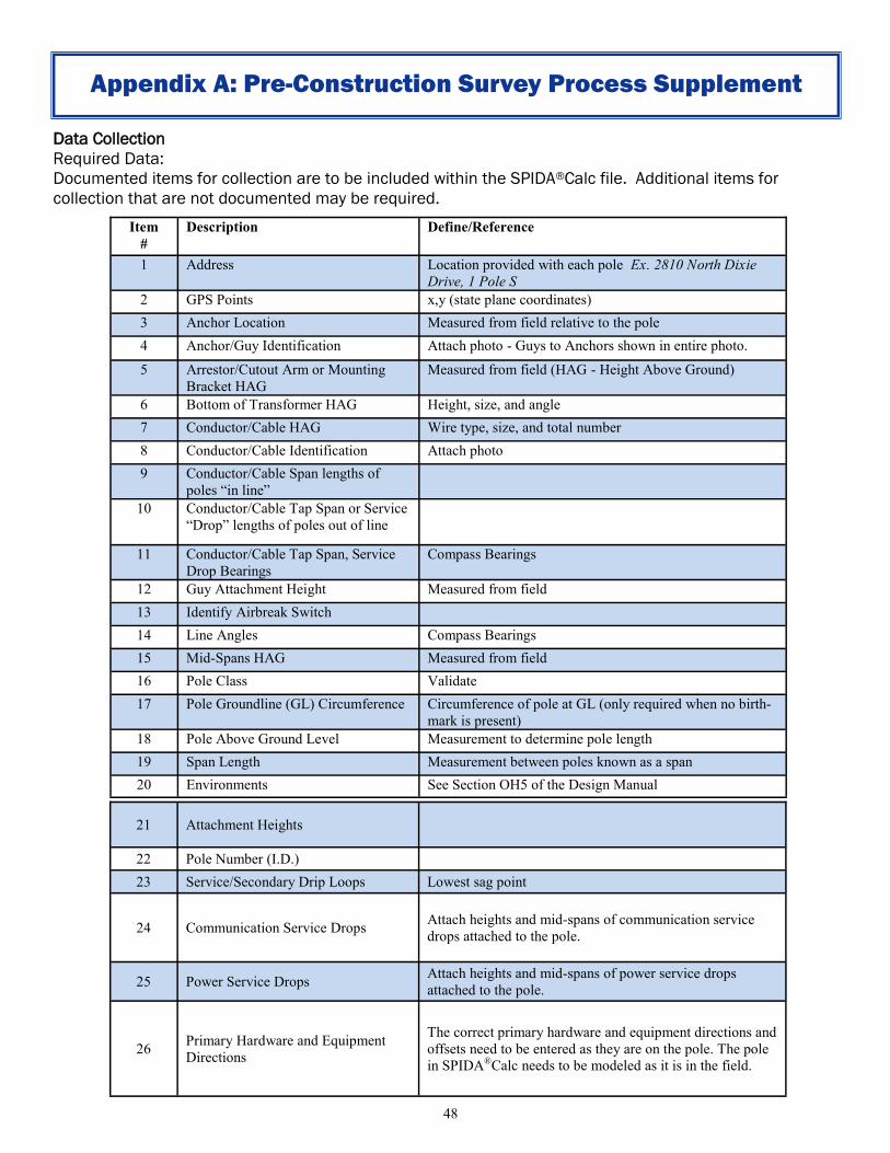
Data Collection
Required Data:
Documented items for collection are to be included within the SPIDA®Calc file. Additional items for
collection that are not documented may be required.
Appendix A: Pre-Construction Survey Process Supplement
Item
#
Description Define/Reference
1 Address Location provided with each pole Ex. 2810 North Dixie
Drive, 1 Pole S
2 GPS Points x,y (state plane coordinates)
3 Anchor Location Measured from field relative to the pole
4 Anchor/Guy Identification Attach photo - Guys to Anchors shown in entire photo.
5 Arrestor/Cutout Arm or Mounting
Bracket HAG
Measured from field (HAG - Height Above Ground)
6 Bottom of Transformer HAG Height, size, and angle
7 Conductor/Cable HAG Wire type, size, and total number
8 Conductor/Cable Identification Attach photo
9 Conductor/Cable Span lengths of
poles “in line”
10 Conductor/Cable Tap Span or Service
“Drop” lengths of poles out of line
11 Conductor/Cable Tap Span, Service
Drop Bearings
Compass Bearings
12 Guy Attachment Height Measured from field
13 Identify Airbreak Switch
14 Line Angles Compass Bearings
15 Mid-Spans HAG Measured from field
16 Pole Class Validate
17 Pole Groundline (GL) Circumference Circumference of pole at GL (only required when no birth-
mark is present)
18 Pole Above Ground Level Measurement to determine pole length
19 Span Length Measurement between poles known as a span
20 Environments See Section OH5 of the Design Manual
21 Attachment Heights
22 Pole Number (I.D.)
23 Service/Secondary Drip Loops Lowest sag point
24 Communication Service Drops Attach heights and mid-spans of communication service
drops attached to the pole.
25 Power Service Drops Attach heights and mid-spans of power service drops
attached to the pole.
26 Primary Hardware and Equipment
Directions
The correct primary hardware and equipment directions and
offsets need to be entered as they are on the pole. The pole
in SPIDA®Calc needs to be modeled as it is in the field.
Page 49
49
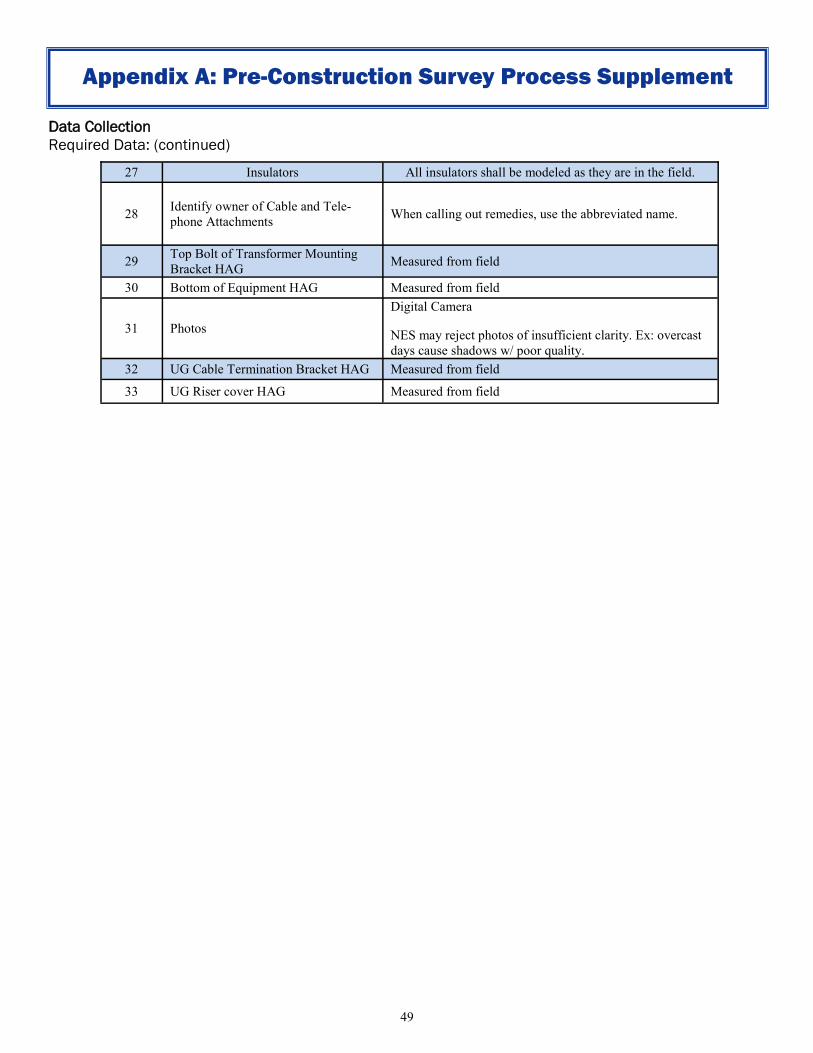
Data Collection
Required Data: (continued)
Appendix A: Pre-Construction Survey Process Supplement
27 Insulators All insulators shall be modeled as they are in the field.
28 Identify owner of Cable and Tele-
phone Attachments When calling out remedies, use the abbreviated name.
29 Top Bolt of Transformer Mounting
Bracket HAG Measured from field
30 Bottom of Equipment HAG Measured from field
31 Photos
Digital Camera
NES may reject photos of insufficient clarity. Ex: overcast
days cause shadows w/ poor quality.
32 UG Cable Termination Bracket HAG Measured from field
33 UG Riser cover HAG Measured from field
Page 50
50
Appendix A: Pre-Construction Survey Process Supplement
Required Pictures Exhibit 1
Page 51
51
Pole Tags
1. Verify the pole tag # at each and every pole.
1.1 If the field number and the map number are different, then record both numbers in the pole tag
section and identify which number is the map number and which number is the field number.
2. If there is no pole owner tag # on the pole you are inspecting, go to the next pole, and verify that pole #
to ensure you are at the correct pole.
3. Properly record any and all other pole tag #’s in the Pole Tags section.
4. On new pole installations, use the GIS number instead of the field number.
Pole Brand
1. Collect the pole height, pole class and material (concrete, steel or wood?)
2. If there is no visible pole brand, in the comments section type: “No Pole Brand" in the comments.
2.2 When a pole brand is not present estimate in the field the Size and Class based off of the GLC
and AGL.
Pole AGL
1. The height above groundline distance.
Pole GLC
1. Groundline Circumference shall be taken at the actual ground line. (When there is no birthmark).
1.1 If there is any type of UG riser attached to the pole measure up to either side of the riser and
then measure the width of the riser (add both measurements) to get your pole GLC
measurement.
1.2 If there is a truss attached at the groundline, measure for pole GLC just as you would with a UG
riser.
1.3 If the Pole is encased in Concrete, record the pole GLC as default. Additionally measure the pole
GLC. Then in the comments section type: “Pole encased in concrete. Measured GLC- xx inches”
Line Angles
1. Line Angles for spans Next (ahead) and Previous (back) will be recorded and based on the mainline of
the electrical circuit. This is not necessarily the route of the communication attachment.
Appendix A: Pre-Construction Survey Process Supplement
Page 52
52
Span Length
1. All span, tap, and service lengths are to be recorded.
Environments
Railroad
Highway
Rural
Street
Parallel to Street
Commercial Driveway
Residential Driveway
Parking Lot
Alley
Farm
Water with Sailboats
Water w/out Sailboats
Pedestrian
Obstructed Parallel to Street
Unlikely Parallel to Street
Attachment Heights
Attachment height measurements should be taken from the same spot as much as possible.
Identifying Down Guys and Anchors
1. When identifying the size of anchors and down guys you will need to utilize a caliper.
1.1 For Anchors
15M = ¾ in. diameter (only 2 eyes)
28M = 1 in. diameter (3 eyes)
32M = 1 ½ in. diameter (3 eyes)
1.2 For Down Guys
1/4 in = ¼ in. diameter
6M = 5/16 in. diameter
12M = 3/8 in. diameter
2. If communication is on an NES anchor, Google will set a new anchor for NES guy at proper
specification then assume the connector to the old NES anchor shared with existing communication.
Primary Hardware and Equipment
1. The correct primary hardware and equipment directions and offsets need to be entered as they are on
the pole. The pole in SPIDA®Calc needs to be modeled as it is in the field.
Insulators
1. All insulators shall be modeled as they are in the field.
Ensure that line extensions are modeled properly.
Appendix A: Pre-Construction Survey Process Supplement
Page 53
53
Mid-spans
1. Mid-span measurements will be taken at the actual mid-span (or close to it) and the environment where the mid
-span is taken will be the environment for the span.
2. If the span crosses multiple environments other than the environment noted for that mid-span location, all
other environments will be spatially located by the use of Span Points in SPIDA®Calc. Additional measurements
will be taken and entered for that span point.
3. Look for crossing mid-spans that could affect movement on a pole. If you see any crossing wires, street lights,
etc. make a note of it, and add a height that this is at if the crossing object is collectable.
4. It is important to note that in some situations you may need to add span points to capture your worst case
between clearances. Be mindful of this when data collecting.
5. Collection of mid-span of rail road crossing should be taken on the rail itself.
Properly Identifying Environments and Span Point
1. If the service span crosses over a front yard and residential driveway, then the environment will be “Residential
Driveway”. You will take the mid-span measurement over the lowest most critical part of the Residential
Driveway.
2. If the service span crosses over a street and yard then the environment will be “Street”. You will take the mid-
span measurement over the lowest most critical part of the Street.
3. If the service span crosses over two different environments with the same required minimum ground clearances
(example: *street and commercial parking lot). Mid-span measurement will be taken at the true mid-span (or
close to it) and the environment where the mid-span is taken will be the environment for the span. In addition
the other environment will be marked by the use of span points.
4. *For certain roads, such as state routes and highways, NES may have greater clearance requirements than
required by the NESC.
5. For more information on environments, see Pole Attachment and Conduit Usage Guidelines section D:
Communication Line Clearance Requirements.
Equipment on Pole
Model all equipment on Pole
The following equipment may be found attached to a pole and should modeled in SPIDACalc.
1. Cutouts
2. Lightning Arresters
3. Termination Brackets
4. Flood Lights
5. Antennas
Determination of Replacing a Pole as Maintenance
If there is room for the new attachment but the pole is overloaded, it may be replaced as maintenance. Poles that
do not have room for the attachment will not be replaced under maintenance. Poles shall be classified as
overloaded if when analyzed the pole is loaded greater than 100%. Overloaded poles must be replaced prior to the
installation of additional attachments. New and replacement poles shall be designed to be loaded less than 80%.
Appendix A: Pre-Construction Survey Process Supplement
Page 54
54
Appendix B: SPIDAMin Procedures
https://spidamin.nespower.com/projectmanager/
Page 55
55
Appendix B: SPIDAMin Procedures
Page 56
56
Appendix B: SPIDAMin Procedures
Page 57
57
Appendix B: SPIDAMin Procedures
Page 58
58
Appendix B: SPIDAMin Procedures
Page 59
59
Appendix B: SPIDAMin Procedures
Page 60
60
Appendix B: SPIDAMin Procedures
Page 61
61
Appendix B: SPIDAMin Procedures
Page 62
62
Appendix B: SPIDAMin Procedures
Page 63
63
Appendix B: SPIDAMin Procedures
Page 64
64
Appendix B: SPIDAMin Procedures
Page 65
65
Appendix B: SPIDAMin Procedures
Page 66
66
Appendix B: SPIDAMin Procedures
Page 67
67
Appendix B: SPIDAMin Procedures
Page 68
68
Appendix B: SPIDAMin Procedures
Page 69
69
Appendix B: SPIDAMin Procedures
Page 70
70
Appendix C: Remediation Procedures
NES Joint Use Remediation Manual
Page 71
71
Appendix C: Remediation Procedures
Table of Contents
Data Auditing ................................................................................................................................. 73
Primary: ..................................................................................................................................... 73
General Formatting Rules- Remediation ....................................................................................... 74
Remedy Box Formatting ............................................................................................................ 74
Documenting Maintenance and Make Ready ........................................................................... 74
Raising and Lower on pole– Order of Remedy Statements ...................................................... 74
Pole Replacements (Comm Down Guys) ................................................................................... 74
Company Nomenclature ........................................................................................................... 75
Determining Maintenance or Make Ready ............................................................................... 76
Solving Overloads .......................................................................................................................... 77
TAF (Tension Adjustment Factor) .............................................................................................. 77
Point Loads ................................................................................................................................ 78
Method 1: In the Field point load collection: ........................................................................ 78
Method 2: In the office point load check: ............................................................................. 78
Slack Spans & Reduced Tension Spans ..................................................................................... 80
General Remediation Statements ................................................................................................. 80
Communication Statements...................................................................................................... 80
Attaching to Pole: .................................................................................................................. 80
Raise or Lower Communication on Pole: .............................................................................. 80
Resag of a Communication Main Line / Cable or Resag and Piece Out: ............................... 80
Communication Services: ...................................................................................................... 80
Raise or Lower Communication Services: ............................................................................. 81
Resag Communication Services: ........................................................................................... 81
Offset Strand Attachment: .................................................................................................... 81
Relash Communication: ........................................................................................................ 81
Transferring Comm for Pole replacement: ........................................................................... 81
Comm Currently Not Attached to Pole: ................................................................................ 81
Double Pole Comm Transfers: ............................................................................................... 81
Crossing Comms: ................................................................................................................... 81
Guying and Anchoring - Communications: ............................................................................... 81
Down/ Span Guying and Anchoring for Communications: ................................................... 81
Down/ Span Guying and Anchoring: ..................................................................................... 82
Removing from an NES Anchor: ............................................................................................ 82
Page 72
72
Appendix C: Remediation Procedures
NES Statements ......................................................................................................................... 82
Raising Neutral / Secondary / Services:................................................................................. 82
Resag of NES Conductor: ....................................................................................................... 82
Retuck Drip Loop: .................................................................................................................. 83
Open Wire Secondary: ........................................................................................................... 83
Street Light: ........................................................................................................................... 83
Antenna: ................................................................................................................................ 83
Guying and Anchoring - NES: ..................................................................................................... 84
Down/ Span Guying and Anchoring for NES: ........................................................................ 84
Down guy Statements: .......................................................................................................... 84
Span Guy Statements: ........................................................................................................... 85
Reinstallation of a Broken NES Down Guy or Anchor: .......................................................... 85
Remove Abandoned Anchor: ................................................................................................ 85
Undocumented Attachment:................................................................................................. 85
Pole Replacement: ..................................................................................................................... 85
NES Remedy Statement for Pole Replacement: .................................................................... 86
Installation of Midspan pole: ................................................................................................. 86
Foreign Pole: .............................................................................................................................. 86
NES Standards: .......................................................................................................................... 87
NES Clearances: ......................................................................................................................... 87
Neutral Spacing Requirements ...................................................................................................... 87
Non-Pole Replacements: ........................................................................................................... 87
Pole Replacements: ................................................................................................................... 87
Pole Replacements with Pole Top or Horizontal Framing ..................................................... 87
Pole Replacements with Vertical Framing............................................................................. 87
Framing Selections: ................................................................................................................... 87
Page 73
73
Appendix C: Remediation Procedures
Data Auditing
Primary: The Data Collector audits wire sizes when they assign photos to ensure 100% accuracy.
The Remediator audits wire sizes when they start the project.
During Design review, again check to ensure that there are no errors.
Page 74
74
Appendix C: Remediation Procedures
General Formatting Rules- Remediation
Remedy Box Formatting - At the start of each remedy line; dash space “- “ - Attachment heights, span lengths, etc. are formatted as; 18’10” - Direction is formatted as; N, S, E, W, NE, NW, SE, SW - Pole height and class is formatted as; 40C4, 50H1 - Capitalize the first letter of a new remedy line
Example remedy box on covermap.
Documenting Maintenance and Make Ready
For pole replacements that are considered maintenance place “MNT:” before the remedy statement. For pole replacements that are considered make ready place “MR:” before the remedy statement.
- MNT: (insert work needed here) - MR: (insert work needed here)
Raising and Lower on pole– Order of Remedy Statements
When raising, lowering or transferring write the remedy in order of movement.
- NES power listed first
- Proposed listed last * *This is based off the assumption the proposed cable is a new attachment (not an overlash attachment) and was not attached to the pole prior to
the field remediation phase of the proposal. If overlash then adjust attachment in order to the overlashed cable being last.
Pole Replacements (Comm Down Guys)
On pole replacements with existing Comm down guys / span guys, it is not necessary to call out a remedy to install these existing Comm guys if they can be transferred.
Page 75
75
Appendix C: Remediation Procedures
Company Nomenclature
When calling out remedies in the ownership box use the abbreviated name. Have to know the nomenclature and, by default, use
whatever it says in SPIDACalc.
Attachment "Owner" Abbreviations & Names Competitive Access Providers
AFG = Access Fiber Group COM= Comcast (Intermedia/Hyperion/Adelphia) TWC = Time Warner Cable (DukeNet)
L3C = Level3 (Telcove) MUNI= MuniNet MET = Metro Government
NESC = NES Communications TCA = Teleport Communications America (ATT Local/TCG) TRS = Traffic and Signalization
TWT = TW Telecom (ICG) VAN = Vanderbilt University
WIND= Windstream (NDL/KDL) XOC = XO Communication (Nextlink)
ZAYO= Zayo (American Fiber Systems/Dolphini) P = Private O = Other/Unknown – (NES use only)
GOOG = Google Fiber Telephone
ATT = AT&T/BST TDS = TDS Telephone UTC = United Telephone Company
Power NES = Nashville Electric Service Power
Page 76
76
Appendix C: Remediation Procedures
Resolving Clearance and Loading Issues Clearances Clearances should be reviewed as a first possible remedy. Resolve clearance issues by moving comms first. This may include at pole attachments and/or pole attachments on adjacent poles. If the issue can’t be fully addressed by moving comms, attempt to resolve by moving power. If Clearance issues are identified, then work required to gain proper clearances should be designated as Make Ready. If the pole is not of sufficient height to allow for proper clearances, then the pole should be replaced as Make Ready. Loading After clearances are reviewed, loading should be evaluated. To solve overloads, try installing down guys, anchors, and/or span guys. For poles with existing overloads, ensure all load imbalances are backed up with guys and all data (heights, GLC, angles) which could affect the loading of the pole is accurate. Exhaust all options before suggesting a Maintenance pole replacement; a pole replacement is the last resort. Classify the work as Maintenance if all the remedy options stated above were considered and the existing pole is still overloaded (greater than 100%).
Classify all other work as Make Ready.
Page 77
77
Appendix C: Remediation Procedures
Solving Overloads
TAF (Tension Adjustment Factor) The NES messengers pole to pole can be adjusted with secondary drops. The adjustments are dependent on the amount of
secondary drops that are coming off of it.
1 cut-in (1000#)
2-3 cut-ins (1500#)
4+ cut-ins (2000#)
When TAF is applied for a midspan tap, the remediator should place a comment in the Calc file under the comments section as outlined below.
TAF APPLIED “# of cut-ins” “Tension applied”
TAF APPLIED 1 cut-in (1000#)
Page 78
78
Appendix C: Remediation Procedures
Point Loads
Span guys that are utilized from the Anchors and Guys tab allow for the tool to assess the actual tension on the span guy by calculating what wires it is supporting. As such, the subsequent pole, if analyzed, will only show a point load equal to the wires that are actually being backed up. This will help greatly in assessing the stresses actually seen on the pole and the analysis will be more in line with the actual field condition.
Point loads can be achieved in 2 ways. Method 1: In the Field point load collection:
Once collection is complete on the pole where the span guy is coming from, and the height of the attachment point on the other pole is collected, run analysis. You will be able to utilize the From Project, or From Previous buttons to bring the point loads through. Upon doing so, a box will appear to choose which loading case the wires should be brought in as. Select the appropriate Medium Load case. This will automatically pull in the point load from the span guy. During your office review before submittal, always use method two to check the force numbers to insure accuracy.
Method 2: In the office point load check:
Point loads will be attained by running analysis on the pole with the span guy affecting the loading on said pole. In the analysis tab, select which span guy you want to apply a point load for.
To the right of the loading analysis, Calc will show “Results for Span Guy #X”. Scroll to reaction forces on that list, select your span guy, and the force will show the numbers needed for the point load.
Page 79
79
Appendix C: Remediation Procedures
On the pole where the span guy forces need to be applied, go to the additional tab to find the point load selection. The inverse of the force numbers will be applied. NOTICE: in our example that the force reads x:2388 y:-125 z: -152 and what we input is x: -2388 y: 125 z: 152.
From there, drag the green point load diamond to the height desired at pole, and it will appear as a green arrow. The arrow should point to the direction of where it came. This will be the way to check every point load to make sure the force numbers are correct
Page 80
80
Appendix C: Remediation Procedures
Slack Spans & Reduced Tension Spans A slack span is defined as approximately ten percent (~10%) normal tension in the NES sag charts. Reduced tension spans are fifty percent (50%) of the design tension. Slack and reduced tension spans should be limited to the range of spans specified on the selected ruling span sag chart in Design Manual section OH1: Overhead Conductor. NES and Other Communication cables should be limited to the range of spans specified on the messenger with Fiber Optic Cable slack span sag charts in Design Manual section OH1: Overhead Conductor.
General Remediation Statements
Communication Statements
Attaching to Pole:
- Attach at x'y''
- Attach span “N,S,E,W” at “x’y”
Possible Additional statements (use on separate line from attach line):
- Ensure x’y” above (environment) through span “N,S,E,W”
- Ensure x’y” from NES conductor through span “N,S,E,W”
Note: Always use both ensure statements when the proposed cable is the only comm going in that direction
Note: Ensure is used for when there is not much room (midspans are going to be tight)
Note: Engineer to ensure minimum 0’4” midspan clearance to communication cable(s) span (N,S,E,W)
Raise or Lower Communication on Pole:
- At x’y” “raise or lower" x’y” to x’y”
- Span “N,S,E,W” at x’y” “raise or lower" x’y” to x'y''
Note: Use when referring to main lines or if multiple lines on pole in different directions
Note: Utilize existing bolt holes when possible; if not possible, maintain minimum 4” to existing bolt holes
Note: When utilizing existing bolt holes, maintain minimum 8” comm to comm
Note: When utilizing existing bolt holes, be aware of the direction of the existing bolt. Ex: dead-end through-bolt vs 3-bolt clamp
Resag of a Communication Main Line / Cable or Resag and Piece Out:
- Resag and Piece Out fiber optic cable (up/down) x’y” to achieve x’y” through span(s) “N,S,E,W”
Note: Always consult your Supervisor prior to using this remedy. This Resag and Piece Out remedy can only be done with Fiber Optic Cable. This can never be done with any solid phone cable (old copper strands / pairs)
Communication Services:
Communication service drops only need to be collected and modeled when attached directly to the pole or when the midspan drop is within three feet (3’) of the pole; however, non-compliant communication service drop clearances still require remediation (notification to owner).
Page 81
81
Appendix C: Remediation Procedures
Note: These attachments do need to be taken into account if rearrangements are taking place at pole, if the
communication services are obstructing the proposed cable, or if the communication services have a clearance violation.
Raise or Lower Communication Services:
- Services on J-hook at x’y’’ “raise or lower" x'y'' to x'y''
- Services on J-hooks “N,S,E,W” attach at x’y”
Note: Any services attached to messengers do not need separate raise or lower instructions
Note: Used when one company has multiple J-hooks with no main line on the pole and are lowering to the same height
- Remove service(s) from J-hook(s) and attach to main cable at x’y”
Note: Used when a company has a main cable and are lowering services to attach to main cable
Note: Anytime raise or lower J-hooks and there is a main cable present, attach to main cable to clean up pole
Resag Communication Services:
- Engineer service(s) to achieve x’y” above “environment” through span “N,S,E,W”
- Engineer service(s) to achieve x’y” from NES conductor through span “N,S,E,W”
Note: Utilize when you need to clarify between clearance to the communication company.
Offset Strand Attachment:
Floating attachments (flying dutchmen) are not allowed on NES Poles, and need to be removed and attach properly to the pole
- Remove from offset strand attachment; attach to pole at x’y”
Relash Communication:
- Relash cable span “N,S,E,W”
Transferring Comm for Pole replacement:
- Attach to new pole at x’y''
Comm Currently Not Attached to Pole:
- Currently not attached; attach to pole at x’y”
Double Pole Comm Transfers:
- Remove from double wood pole; attach to new pole at x’y”
Crossing Comms:
- Coordinate with (owner) to ensure NESC between clearance to crossing communication cable
Guying and Anchoring - Communications:
Down/ Span Guying and Anchoring for Communications:
Operator should guy all proposed load imbalances, angles, and dead-ends.
If the Operator identifies another comm providers facilities that are unguyed, Operator should make provisions for and prescribe that the other comm guy their facilities.
Page 82
82
Appendix C: Remediation Procedures
When other comms facilities are guyed, the operator is not expected to solve the other comms guy overload if one is discovered.
Installation of the Operators’ facilities should not make overloads on existing comm guys worse.
Down/ Span Guying and Anchoring:
- Engineer down guy and anchor to support span “N,S,E,W” - Engineer down guy and anchor to support on bisector - Engineer down guy to support “on bisector or for span” “N,S,E,W” and attach to NES anchor with a lead of x’y”
Note: NES will allow a Comm to attach to their anchor in unusual situations. These will be reviewed on a case by case basis. The most common example will likely be when there is some physical/environment conditions that prevent the extension of an existing anchor lead. Another less common, but possible situation may be if a property owner refuses to grant an easement.
- Re-Tension down guy(s) at x’y” “on bisector or for span” “N,S,E,W” - Engineer span guy to pole “XXXXXX” “N,S,E,W” to support on bisector - Engineer span guy to pole “XXXXXX” “N,S,E,W” to support span “N,S,E,W” - Attach span guy at x’y” from pole “XXXXXX” “N,S,E,W” Note: This statement is used on the pole the new span guy is going to - Ensure NES clearances for anchor placement
Note: ALWAYS USE THIS REMEDY STATMENT - Coordinate with NES right of way to secure necessary easements for new NES anchor
Note: USE WITH NES EXTENSION. This will fall under what company is causing NES to extend
Removing from an NES Anchor:
- Remove down guy from existing NES anchor “on bisector or for span” “N,S,E,W” - Engineer to install new down guy and anchor to support “on bisector or for span” “N,S,E,W” - Ensure NES clearances for anchor placement
Note: ALWAYS USE THIS REMEDY STATEMENT
NES Statements
Raising Neutral / Secondary / Services:
Call for splicing of all NES services if you are raising them or replacing a pole with services. Reference NES Framing Criteria and Construction Standards for spacing requirements. When raising Neutral or Secondary with no equipment on pole be aware of spacing on the pole with potential of a transformer being installed. Consult with supervisor.
- “wiretype” at x’y” “raise or lower” x’y” to x’y” - "wiretype" “services” span "N,S,E,W" at x'y" "raise or lower" x’y” to x'y'' - "wiretype" span "N,S,E,W" at x’y” "raise or lower" x'y'' to x’y'' - Splice in additional “wiretype” for span “N,S,E,W” Note: Span direction statement should only be used for dead-end attachments
Resag of NES Conductor:
- Resag “wiresize” at x’y” [RSXXX-wiresize-tension] (up/down) x’y” to achieve x’y” above (environment) through span "N,S,E,W"
Page 83
83
Appendix C: Remediation Procedures
Note: RSXXX-wiresize-tension is the tension of the wire from the sag chart Note: The at x’y” height in the remedy statement is for midspan height; not attachment height at pole
Retuck Drip Loop: - Retuck Power drip loop at x’y” (up/down) x’y” to x'y''
- Retuck STLT drip loop at x’y” (up/down) x’y” to x'y''
Open Wire Secondary:
The size of the triplex that the copper open wire is being replaced with is dependent on the size of the existing copper, transformer size, and actual load demand. Both poles in an open wire change outs are included since NES work is required. - Replace “wiresize” open wire for span “N,S,E,W” with a “wiresize”; attach at x’y” - Remove three (3) wire rack at x’y” - Install single wire rack and attach “wiresize” at x’y” Street Light:
Note: STLT= Street light The top or bottom of the STLT bracket shall be no closer than six inches (6”) to the Neutral. The STLT shall not be raised or lowered
into the secondary wire. If raising or lowering the STLT bracket more than five feet (5’0”) from the existing position, submit the
following information to begin the photometric review (additional information may be required, including but not limited to a
detailed photometric study):
- STLT at x’y” (bottom) “raise or lower” x’y” to x’y”
A proposed cable is allowed to attach to a wood STLT pole but will be denied attachment on decorative poles. Antenna: If an antenna is raised, this should be noted in the remedy statements for review by NES. Antenna heights are taken from the bottom of the antenna. An antenna should never be lowered. - Antenna at x’y” (bottom) raise x’y” to x’y”
Lowest Power for Antenna
Page 84
84
Appendix C: Remediation Procedures
Guying and Anchoring - NES:
Down/ Span Guying and Anchoring for NES: • Overloaded NES Guys and Anchors will always need to be solved. • Review which conductors/cables are guyed at every pole. Make note of where new guys are needed. Installing new guys and
anchors or increasing the lead of existing guys may solve an existing overload or prevent a proposed overload. If there are any comms that are not guyed, direct them to guy their facilities in the remedy.
Buried anchors will be addressed as a part of the Pole Inspection/ Treatment program or pole replacement.
An NES anchor can be placed outside the existing location and abandoned for a proposed company to attach.
Crossing down guys need to be solved if proposed company is installing in same direction or NES down guy/anchor is overloaded.
Maintain minimum anchor clearance to NES Anchors is five feet (5’)
Any new NES down guy installs will be 12M. An exception: 6M may be installed for neutral when attaching 3 down guys to one anchor
Down guy Statements:
- Remove existing “size” down guy at x’y”; abandon existing anchor for “span N,S,E,W / bisector” with a lead of x’y” Note: Utilized when communication will use NES abandoned anchor - Remove existing “size” down guy at x’y” and “size” anchor for “span N,S,E,W/bisector” with a lead of x’y” Note: When removing both down guy and anchor - Remove existing “size” down guy at x’y” from existing “size” anchor on the bisector with a lead of x’y” Note: Utilized when NES will continue using their anchor - Install "size" down guy at x’y” and “size” anchor for span “N,S,E,W” with lead of x’y” - Install "size" down guy at x’y” and “size” anchor on the bisector with lead of x’y” - Install “size” down guy at x’y” to existing “size” anchor on the bisector with a lead of x’y” - Install “size” down guy with (12”, 54”, 120”) FGI and “size” anchor on the bisector with a lead of x’y” Note: Utilized when guys need to be insulated - Re-Tension down guy(s) at x’y” “for span N,S,E,W or on bisector” - Ensure NES clearance for anchor placement
Note: ALWAYS USE THIS REMEDY STATEMENT
Page 85
85
Appendix C: Remediation Procedures
Span Guy Statements:
- Install "size" span guy “with Johnny ball or (12”, 54”, 120”) FGI” at x’y'' to pole “XXXXXX” “N,S,E,W” Note: Johnny ball used for 4kV Note: Fiberglass link stick used for 13.8 & 23.9 kV - Attach “size” span guy at x’y” from pole “XXXXXX” “N,S,E,W”
Note: To be used on the pole the span guy is going to
Reinstallation of a Broken NES Down Guy or Anchor:
- Install new “size” down guy at x’y” and attach to existing anchor for span “N,S,E,W” with a lead of x’y” Note: Use when only down guy is broken and anchor still exist
- Install new “size” down guy at x’y” and “size” anchor for span “N,S,E,W” with a lead of x’y”
Note: Use when only anchor is broken/missing - Install new “size” down guy at x’y” and “size” anchor on the bisector with a lead of x’y”
Note: Use when only anchor is broken/missing
Remove Abandoned Anchor:
- Remove abandoned anchor for span “N,S,E,W” with a lead of x’y” Note: Use when existing abandoned anchor
Undocumented Attachment:
Record undocumented attachment(s) in SPIDACalc summary notes for NES review.
Pole Replacement:
All pole replacements shall utilize existing stock size & class poles. Reference the "Standard Pole Sizes" chart in section OH2 of the Design Manual. New poles shall be designed to be loaded to 80% of capacity or less.
Steel poles: 50’ – H1, H3 55’ – H1 60’ – H3, H5, H8 65’ – H3, H5 70’ – H3, H5 75’ – H3
When a pole is to be replaced use the Deflection Check in loading. The pole top Deflection shall be no more than 1.66% of the
pole height above ground. (EX: 50’C1 installed at standard depth of seven feet (7’) is forty three feet (43’) above ground. 0.0166 X 43’ = 0.71’. 0.71 X 12 = 8.56”.
Poles should be raked when the deflection is 6” or greater.
Reference NES Framing Selection Standards for proper Framing.
Residential Neighborhood: If there is equipment (except transformer or cutouts) on the
pole or a primary riser then the replaced pole needs to be Weathering Steel If all of the existing poles are Galvanized steel then change it to Galvanized Steel Do not install Weathering Steel poles in sidewalks.
Commercial Area:
Page 86
86
Appendix C: Remediation Procedures
Pole replacements in commercial areas can be Wood or Galvanized Steel Reference “Pole Material Properties” located in the Structures section of the NES Design Manual for more information
regarding pole types and replacement guidelines.
NES Remedy Statement for Pole Replacement:
- Replace “height””CorH””Class size” with a “height””CorH””Class size” (ie: 45C2 with a 50H1) - Construct to “Enter all framing construction standards that apply” - Attach Neutral no lower than x’y” - Attach Secondary/Services no lower than x’y” - Ensure Power drip loop no lower than x’y” - Install new (size) down guy at x’y” and (size) anchor for span “N,S,E,W” with a lead of x’y” - Install STLT at x’y” (bottom)
Note: The Framing remedy statements should be put in vertical order (top, middle, bottom). Framing should be examined in the framing selection Standards. Note: Pole replacements may require new NES down guys and anchors. Place the new anchor 5’ from the existing anchor to ensure quality of the ground for new anchor
Installation of Midspan pole:
This is extremely rare
Follow “Pole Replacement” format on new midspan pole On Existing Pole: - Install “height””CorH””Class size” pole xxx’ “N,S,E,W” At New Midspan Pole Location: Callout should be the same as a normal pole replacement remedy.
Foreign Pole:
Violations should be attempted to be solved on NES poles but if work on a foreign pole appears to be possible to solve any remaining violations on a NES pole and we don’t make the existing condition worse, we may tell the company to solve remaining violations on foreign pole XXXXXX
Foreign Poles may be used to install a span guy to. Make sure the pole number is known
An issue can be fixed on a foreign pole, we cannot make the situation worse. - Solve remaining midspan "between or ground" clearance span "N,S,E,W" on foreign pole “XXXXXX”
Note: Can use / add ensure statement if you need a certain clearance For all new NES span guys added to a foreign pole, the following steps must be completed:
Collect the foreign pole after remediation if NES attachment will be needed
Model the foreign pole in the calc file and run the loading (ensure at pole clearances and NES midspan clearances)
Create remedy statements for the foreign pole
Add the foreign pole to the CM but do not include in the exhibitA
Span guy AND down guy/anchor will need to be included on the MNT/MR sketch
Add CU units in the WO for the NES work to foreign pole
Page 87
87
Appendix C: Remediation Procedures
NES Standards: Refer to NES Overhead and Underground design standards found on NES Intranet under the Customer Engineering department. These standards are under the “plate book” link.
NES Clearances: Refer to NES Clearance Standards for specifics.
Neutral and Framing Spacing Requirements
Non-Pole Replacements: Existing NES poles may not meet current spacing or framing standards. In certain situations, it may be acceptable to raise the Neutral or Secondary on the pole. See the Framing Spacing and Framing Standards sections of the Transmission and Distribution Construction Plate Book for more details. NES may have the latitude to raise conductors when they fall in these situations:
Neutral spacing greater than preferred Raising the Neutral is allowed but must maintain preferred spacing. Example: If existing Neutral spacing on crossarm framing measures 9’-6” it may be raised to 8’-4”.
Neutral spacing less than preferred but greater than preferred minus 2’. The Neutral may be raised to preferred minus 2’. Example: If existing Neutral spacing on crossarm framing measures 7’-6” it may be raised to 6’-4”.
Neutral spacing less than preferred minus 2’. Raising the Neutral is allowed up to the minimum. Example: If existing Neutral spacing on crossarm framing measures 5’-6” it may be raised to the 4’ minimum.
Note: Neutral spacing dimensions in the T&D framing standards sections not labeled minimum are preferred. Note: Reflect any proposed reductions to spacing under the Design Details tab in the SPIDACalc location form. Note: Preferred minus 2’ is not allowed if it results in clearance less than minimum. Note: If a pole has any equipment installed, Neutral must meet preferred spacing for that framing.
Pole Replacements: NES requires all Neutral and Framing spacing to meet the criteria outlined below. See the Framing Spacing and Framing Standards sections in the Transmission and Distribution Construction Plate Book for more details.
Framing Spacing
Build to the NES construction standards with preferred Neutral spacing.
Ensure all equipment transferring to the new pole follows proper construction standards.
Exception: May reduce framing spacing to less than preferred but not less than minimum to avoid an additional 15’ taller
pole. Note: Framing spacing dimensions in the T&D framing standards sections not labeled minimum are preferred. Note: Reflect any proposed reductions to spacing under the Design Details tab in the SPIDACalc location form.
Framing Selections: The construction standard used for a pole replacement is based on the type of construction (pole top, horizontal, or vertical), size of primary wire(s), span length, and the line angle. When replacing a pole, in almost all cases, replacing with same type of construction will be preferred – assuming it falls within the current framing criteria located in the Transmission and Distribution Construction Plate Book for the aforementioned variables. Each replacement is unique so refer to the NES 1P, 2P and 3P framing selections.
Page 88
88
Appendix D: Summary of Changes for this Revision
This guideline has undergone extensive modification. The following list of changes are not intended to
be inclusive of all changes such as re-wording, clarifications, or corrections.
1. Clarification of 1.1 bullet points. Moved one note to 1.2. Page 12
2. Clarified character height restrictions. Page 16
3. Added NES clarification to Power and Communication Anchor references and added Guying
Exceptions. Page 22
4. Added notes and clarified dimensions. Page 27 and 28
5. Clarified and fixed dimensions. Page 29
6. Revised note 1. Page 30
7. Removed Wireless equipment note and fixed number. Page 31
8. Added note 6 for existing risers. Page 32
9. Modified cabinet dimensions, 3.3. Page 33
10. Clarified and added dimensions. Page 35
11. Moved “with street light” example to follow other equipment attachment page. Page 36
12. Revised notes. Page 37
13. Changed antenna riser to secondary clearance to 40” Page 39
14. Removed antenna and wireless note. Page 40
15. Added Rural, Obstructed and Unlikely parallel to street environments. Page 52
16. Revised Environments language and clarified when a pole is replaced under maintenance. Page 53
17. Added Spidamin web address. Page 54
18. Fixed page numbers. Page 71 and 72
19. Changed header. Page 76
20. Added “Engineer to ensure minimum 0’4” midspan clearance…” Page 80
21. Removed raise conductor if transformer exists. Page 82
22. Revised Street Light section. Page 83
23. Revised Neutral clearance definitions and when reduced framing spacing can be used. Page 87