www.vbripress.com/aml, DOI: 10.5185/amlett.2016.6011 Published online by the VBRI Press in 2016
Poly(3, 4-ethylene dioxythiophene) grafted multiwalled carbon nanotube decorated polyurethane foam for antistatic and EMI shielding applications
M. Farukh1,2 and S. K. Dhawan1* 1Polymeric & Soft Materials Section, CSIR-National Physical Laboratory, Dr. K. S. Krishnan Road, New Delhi 110012, India 2Academy of Scientific and Innovation Research, CSIR-National Physical Laboratory, Dr. K. S. Krishnan Road, New Delhi 110012, India *Corresponding author. Tel: (+91) 11-45609401; E-mail: [email protected] Received: 04 June 2015, Revised: 01 December 2015 and Accepted: 29 April 2016
Keywords: PEDOT; MWCNTs; PU foam; EMI shielding; anti-static decay.
Introduction
PU is one of the most popular foam material and continuing to grow at a progressive rate throughout the world. This rapid increase in interest can be attributed to the exotic properties like light weight, excellent mechanical strength, and energy absorbing behaviour (including shock,
vibration, and sound) [1-3]. PU foams are widely used as soles, building materials, thermal insulation, bedding, and packing materials. However, PU foams are insulating in nature with volume resistivity of about 1010 to 1013Ω cm which can result in the build-up of high static charge. Static charge severely damages electronic devices and electronic
components when discharge due to electric spark [4]. Thus it is very important to improve conductivity of PU foam for anti-static application. Another very important application for which conducting PU foam can be utilized is EMI
shielding materials are of great importance for the reduction of electromagnetic noise since electromagnetic (EM) waves adversely affect the functionality of the
electronic equipments [6], particularly in the areas of stealth and aviation technology. These microwaves are also
very harmful to the health of the human beings [7],
therefore it is mandatory to shield EM waves [8]. The electrical conductivity can be imparted to the PU foam by
coating it with light weight intrinsically conducting polymers. In the recent decades intrinsically conducting polymer (ICPs) composites have shown great potentials in the areas of EMI shielding and anti-static coatings. Flexible and lightweight are two very important properties required for most technological applications to save material and energy. Therefore much attention has been paid to the development of peculiar light weight shielding materials
several advantages over conventional metal based EMI shielding materials like resistant to corrosion, good processability, tunable conductivity, economic and flexibility. The EMI shielding efficiency and electrical conductivity of conducting polymer composites depends on intrinsic conductivity, high aspect ratio, and concentration of electrically conducting filler. Carbon nanotubes (CNTs) have high mechanical strength and modulus, good electrical conductivity and excellent chemical stability, and high aspect ratio which make them useful electrically conducting filler for the preparation of polymer grafted CNT composite
[15,16]. Recently, several efforts have been made by researchers to make conducting foam for different applications. For instance, Kannaiyan et al. reported polyaniline coated polyurethane foam for pressure sensing applications by in situ polymerization of aniline on
superelastic, flexible three-dimensional (3D) graphene/polyimide based architectures for strain sensor
applications [18]. Cheng et al. synthesized grapheme/polydimethylsiloxane composite foam by chemical vapour deposition and reported an electrical conductivity of 10 Scm-1 at 0.5 wt % graphene loading
[19]. Gupta C et al. fabricated CNT/polystyrene foam composites for EMI shielding applications and obtained shielding effectiveness of 18 dB at 7 wt % loading of CNTs
[20]. Zhang et al. prepared lightweight and flexible composite films of waterboure polyurethane/MWCNTs which showed a shielding effectiveness of 80 dB at a
critical thickness of 0.8 mm in the X-band frequency [21]. Ren W et al. reported fabrication of highly conducting light weight graphene/polymer foam by chemical vapour
deposition for EMI shielding applications [22]. In the present work two kinds of approaches are used to
impart electrical conductivity to PU foam; first was dip coating and another was in-situ coating of PU foam. In the dip coating method PU foam was made conductive, simply by immersing it in aqueous PEDOT: PSS dispersion while in other method PEDOT DBSA grated MWCNTs composite was polymerized over PU foam.
PEDOT an intrinsically conducting polymer is widely used for anti-static coatings and organic solar cell applications. PEDOT possess high environmental stability, outstanding transparency in doped state, low band gap, and
high conductivity [23, 24]. Herein, we have synthesized PEDOT in a medium containing multi walled carbon nanotubes (MWCNTs) as a template which results in the formation of unique PEDOT grafted MWCNT composite. Saini et al. reported that at a critical concentration of MWCNTs in the monomer solution, the polymerization
takes place exclusively on the surface of MWCNTs [25], which results in the formation of PEDOT grafted MWCNT composite (PCNT). However, it is difficult to use PCNT composite as such due to its poor mechanical properties. Hence, we decorated polyurethane (PU) foam with PCNT composite via in-situ polymerization route. We also compared the properties of PCNT decorated PU foam with commercially available PEDOT: PSS dip coated PU foam. In addition to high stability, good conductivity and transparency in doped form PEDOT: PSS have very good film forming properties, which was utilized to for dip
coating of PU foam [26]. The resulting PCNT and PEDOT: PSS decorated PU
foams show good electrical conductivity required for EMI shielding and anti-static applications. The foam samples were characterized by XRD, SEM, FTIR TGA and conductivity meter. The EMI shielding and anti-static measurements were done on Agilent’s vector network analyzer E8362B and JCI 155v5 charge decay test unit.
Experimental
Materials
The EDOT monomer is supplied by TCI, chemicals and is used as such without further distillation. Dodecyl benzene sulfonic acid (DBSA) was procured from Acros Organics (Belgium). Isopropyl alcohol (IPA) and N, N-dimethyl formamide (DMF) were obtained from Qualigen, India.
The PEDOT: PSS 1.3 wt % dispersion in H2O was purchased from Sigma Aldrich, India. Ammonium per sulphate (APS) was obtained from Merck, India. The MWCNTs were synthesized in-house by chemical vapour deposition (CVD) using toluene and ferrocene as precursor and catalyst, respectively. The purity of MWCNTs was 90 % with diameter ranges between 20-50 nm and length
between 50-100 nm [12]. Preparation of PEDOT: PSS coated PU foam
The PEDOT: PSS coated PU foam was prepared by simple dip coating method. The dip coating was performed at room temperature by immersing the PU foam in the aqueous dispersion of PEDOT: PSS and then kept soaking for half an hour. Thereafter, PEDOT: PSS soaked PU foam was kept in vacuum oven for drying at 60 ºC. The morphology of resulting PEDOT: PSS coated PU foam was characterized by SEM which shows uniform coating of PEDOT: PSS over PU foam. Preparation of PCNT coated PU foam
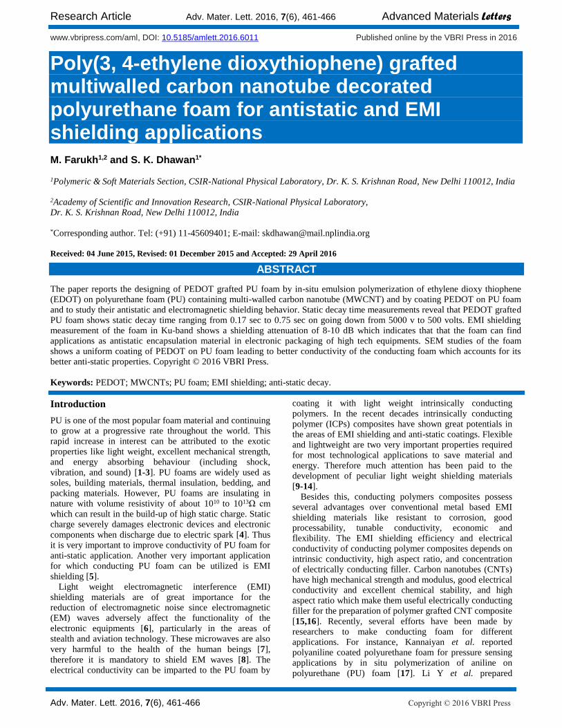
The PCNT coated PU foam was prepared by in situ polymerization of PEDOT in the presence of MWCNTs
(Fig. 1). Initially, 0.1 M EDOT, 0.3 M DBSA and MWCNTs were taken in a beaker and then homogenized at 12000 rpm for 2 hrs to form a stable emulsion. MWCNTs added were 1/4th to the weight of the monomer EDOT. After homogenization the PU foam is put into emulsion and allowed to soak with the emulsion. After those 0.1 M APS was added dropwise to the solution with continuous shaking on a rotary shaker. After 6 hrs PCNT decorated PU foam was obtained which is then washed with distilled water and then dried in vacuum oven for 24 hrs at 50 ºC.
Fig. 1. Schematic showing in situ coating of PCNT over PU foam.
Material characterization
The morphological analyses of foam samples were investigated by scanning electron microscope (SEM) (Zeiss EVO MA-10) at an accelerating voltage of 10 kV. X-ray diffraction (XRD) studies were carried out using D8 Advance XRD (Bruker) using Cu K-α radiation (λ=1.54 A◦) in the scanning rate of 0.02°/sec. The Fourier Transform Infrared (FT-IR) spectra were recorded on a Nicolet 5700 in transmission mode in the wave number range 400-4000 cm-1. The Raman spectra were recorded by Renishaw in Via Reflex Raman Spectrometer, UK, with an excitation source of 514.5 nm and 2.5 mW power. The thermal behaviour of the composites were studied using
Research Article Adv. Mater. Lett. 2016, 7(6), 461-466 Advanced Materials Letters
thermogravimetric analysis (TGA) (Mettler Toledo TGA/SDTA851) in the temperature range 25-600oC under nitrogen atmosphere. The room temperature electrical conductivity measurement was obtained by standard four probe method using computer controlled Keithley current source (Model 6221) and nano-voltmeter (Model 2182A). Anti-static measurements were carried out by using JCI 155v5 charge decay test unit. Electromagnetic shielding measurements have been carried out using Agilent E8362B Vector Network Analyzer having coaxial cable attached with rectangular waveguide of Ku-band dimension.
Fig. 2. SEM micrographs of bare PU foam (a), PEDOT: PSS coated PU foam (b) and (c).
Results and discussion
Morphological analysis
SEM was performed to visualize the morphology of the
macroporous PU foam (see Fig. 2). From Fig. 2(a) it can be observed that the bare PU foam without coating had a highly porous structure, consisting of open pore channel and inter-connecting framework and the pore size was
between 200-400 μm. Fig. 2(b, c) shows the PEDOT: PSS dip coated PU foam at low and high magnification,
respectively. It is evident from the Fig. 2(b, c) that morphology of the PU foam does not changed after coating with PEDOT: PSS. This can be attributed to the excellent film forming property of the PEDOT: PSS.
Fig. 3 shows in-situ polymerized PCNT over PU foam.
Fig. 3(a) shows that the open cell structure of the PU foam was not affected by in-situ coating of PU foam with PCNT.
Fig. 3(b) shows strut surface of the PCNT coated PU foam
which is rougher than the bare PU foam. Fig. 3(c) and (d) shows high magnification images which establish that the PCNT was uniformly distributed over the surface of the PU foam thereby resulting in the formation of electrically conducting network over the surface of PU foam.
To determine the size and core shell structure of the PCNT, we carried out the SEM and TEM of the PCNT collected from the reaction vessel used for in-situ
polymerization process. Fig. 4(a) shows SEM image of PCNT, PEDOT is uniformly grafted over MWCNTs and
look like rods of snowflakes with the size around
150-200 nm. Fig. 4(b) shows TEM image of the PCNT where uniform coating of PEDOT polymer over MWCNTs was observed. The thickness of the PEDOT layer was found to be ~45 nm and diameter of the MWCNT was ~48 nm.
Fig. 3. SEM images of PUPCNT foam at low magnification (a), PUPCNT foam strut at low magnification (b), and surface of PUPCNT foam strut at high magnification revealing uniform coating of PCNT.
Fig. 4. SEM of PCNT composite (a), TEM image confirming the coating of PEDOT over MWCNT (b)
In order to determine the crystallinity of the materials XRD measurements were carried out. XRD patterns of the samples including MWCNTs, bare PU foam, and PEDOT:
PSS and PCNT coated PU foam are shown in Fig. 5(a). MWCNTs shows diffraction peaks at 26.5o for (002) plane and at 42.5o for (100) plane corresponding to the inter layer
spacing of 0.34 nm and 2.12 nm, respectively [27]. The bare PU foam and PEDOT: PSS coated foam shows no diffraction peaks, but broad diffraction peaks are observed
at 24.5 which confirms their amorphous nature. In case of PUPCNT foam besides, a broad peak at 24.5o and an additional peak was also observed at 26.5o attributed to the (002) plane of the MWCNT which supports the co-existence of PCNT coated PU foam.
Fig. 5. (a) XRD patterns of PUPCNT, PUP, PU foam samples and
MWCNT; (b) Raman spectra of PUPCNT, MWCNT, and PU foam samples; (c) Thermogravimetric plots of PU, PUP, and PUPCNT foam samples from 25 to 600 oC; (d) Variation in DC conductivity of PU, PUP and PUPCNT foam sample.
Raman studies
Fig. 5(b) shows the Raman spectra of PU foam, MWCNT, and PUPCNT (PCNT coated PU foam). The spectra of PU foam consist of peaks at 1324 and 1623 cm-1 due to the C‒N/C‒O and aromatic C=C bond vibrations. The MWCNTs shows characteristic G and D band at 1582 cm-1 due to the in-plane vibration of the C ̶ C bond and 1342 cm-1 because of disordered carbon systems,
respectively [28]. The Raman spectra of PCNT coated PU foam shows all the characteristic peaks of PEDOT confirming the formation of PEDOT. The band related to PEDOT structure are as follows; the bands near 1561 and
1526 cm-1 can be assigned to Cα Cβ anti-symmetric vibrations in the aromatic thiophene ring. The peaks at 1429 cm-1 is due to symmetric stretching deformations in Cα ̶ Cβ group. The band at 1366 cm-1 is due to Cβ-Cβ
stretching deformations in the aromatic thiophene ring. There are a number of bands of PEDOT arises due to Cα-Cα inter-ring stretching at 1258 cm-1, C-O-C deformation at 1097 cm-1, oxyethylene ring deformation at 995 cm-1, C-S-C deformation at 697 cm-1, oxy-ethylene deformation at 577 cm-1, and SO2 bending at 439 cm-1
[29, 30] are also present in the spectra. The MWCNT peaks suppressed by the peak of PEDOT, and hence not appears in the spectra.
Thermogravimetric analysis
Fig. 5(c) shows the thermogravimetric analysis of the bare PU foam, PUP foam and PUPCNT foam. The degradation of PU starts with decomposition of urethane bond at temperature between 150 and 200 oC and is affected by the presence of substituents on the isocyanate and polyol side
[31]. All three samples show a two-step degradation mechanism. The 5 % weight loss of PU foam occurs at 271oC while of PUP and PUPCNT samples, it is 268 and 228 oC, respectively. The difference in the 5 % weight loss of the PUP sample is very small (3 oC), due to the very thin film coating of PEDOT: PSS over the surface of PU foam. On the other hand, there is high difference in the 5 % weight loss of the PUPCNT sample which is due to the less thermal stability of PEDOT polymer, and also reveals that thick layer of PCNT was deposited over the surface of the PU foam. The first step of degradation in the PU and PUP foam samples can be attributed to the decomposition of isocyanate group at ~ 220 oC. In case of PUPCNT foam sample first step of degradation occurs at 180 oC due to the removal of dopant molecules in PEDOT polymeric chain. The second degradation step appearing at 360-390 oC can be ascribed to the decomposition of soft part of PU foam and PEDOT polymer in the PUP and PUPCNT samples.
Table 1. Room temperature DC conductivity of PU, PUP and PUPCNT foam samples showing variation in specific shielding effectiveness (dB) and anti-static decay (s) with increase in conductivity.
S. No. Foam
Sample
Conductivity
S/cm
Specific EMI SE
at 18 GHz (dB)
Antistatic Decay (s)
1/e 10%
1. PU 1.33 x 10⁻¹¹
11 92.4 413.5
2. PUP 3.1 x 10⁻⁴
105 0.171 0.75
3. PUPCNT 5.3 x 10⁻¹
220 0.1714 0.544
DC electrical conductivity
The room temperature DC electrical conductivity of the foam samples were obtained by measuring resistance of the samples using standard four probe method. The conductivities of the foam samples were calculated by the
formula, . Where, L is the length of the foam, R is resistance and A is the cross-sectional area of the foam normal to the direction of current flow. It is observed that the conductivity of the coated foam samples increased by simple dip coating with PEDOT: PSS to 6-7 orders and by in-situ polymerization processes to 10 orders of magnitude. This enhanced conductivity is due to the presence of MWCNTs in the PEDOT matrix. MWCNTs possess high electrical conductivity, which further enhances the conductivity of the PEDOT to several order of the magnitude in the PCNT composite, due to this conductivity of the PUPCNT is higher than the PUP foam. It is well known fact that EMI shielding and anti-static properties
increases with conductivity (see Fig. 5(d) and Table 1).
Anti-static studies
Static charge decay studies of PU foam samples were carried out by JCI 155v5 charge decay test unit at corona
Research Article Adv. Mater. Lett. 2016, 7(6), 461-466 Advanced Materials Letters
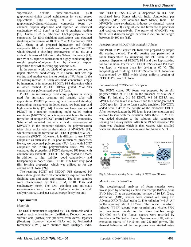
voltage of 5.0 kV. From Fig. 6(a) it is observed that bare PU foam shows a peak at ~550V which means that bare PU foam accepted only 11 % of the applied voltage (5 kV). Moreover, the deposited surface charge decays to 1/e and 10 % of the initial voltage in 92.4 and 413.5 s which are much higher than the criterions set for 1/e (less than half a
second) and for 10 % (less than 2 seconds) [32, 33]. However, PUP and PUPCNT foam samples show drastic decrease in the charge accept and retention ability due to
rapid charge dissipation (see Fig. 6(b) and (c)). Hence, PUP sample receives 90 V when 5 kV was applied to its surface and dissipates charge within the criterion limit. The PUP sample takes 0.171 and 0.75 second to dissipate 1/e and 10 % of the charge deposited, respectively within the set criterions. Similarly, PUPCNT sample dissipates 1/e and 10 % of charge in 0.17148 and 0.5445 seconds, respectively. The excellent charge dissipation properties in the PUP and PUPCNT samples result due to the formation of conducting path over the surface of foam samples.
(a)
(b)
(c)
(c)
(b)
Fig. 6. Plots of variation of static decay time at 1/e and 10% surface voltage for the various samples of foam
EMI shielding effectiveness
The EMI shielding effectiveness of a material is the ability to attenuate/reduce the power of the incident and transmitted radiation. EMI shielding depends on three
mechanisms [34, 35], (a) reflection from the surface of the shield, (b) absorption when wave goes inside bulk of the material, and (c) multiple reflections from the various interfaces of the shield. Hence, EMI shielding effectiveness
can be expressed as [15, 36],
(1)
When shielding effectiveness due to absorption is
greater than 10 dB, multiple reflections can be ignored
safely [37] and the eq. 1 reduces to:-
(2)
SEA and SER can further be described as:
(3)
(4)
where, T and R are transmittance and reflectance,
respectively, derived from scattering parameters as:
(5)
(6)
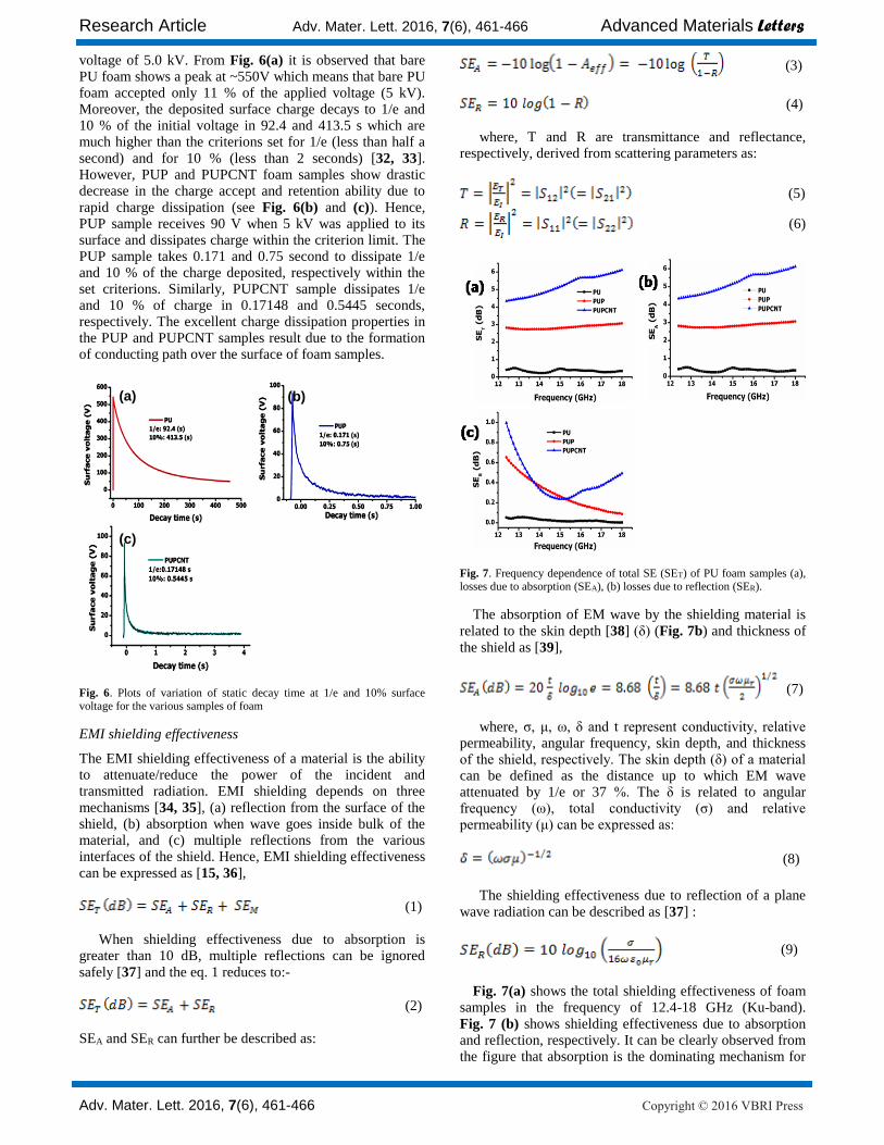
Fig. 7. Frequency dependence of total SE (SET) of PU foam samples (a), losses due to absorption (SEA), (b) losses due to reflection (SER).
The absorption of EM wave by the shielding material is
related to the skin depth [38] (δ) (Fig. 7b) and thickness of
the shield as [39],
(7)
where, σ, μ, ω, δ and t represent conductivity, relative
permeability, angular frequency, skin depth, and thickness of the shield, respectively. The skin depth (δ) of a material can be defined as the distance up to which EM wave attenuated by 1/e or 37 %. The δ is related to angular frequency (ω), total conductivity (σ) and relative permeability (μ) can be expressed as:
(8)
The shielding effectiveness due to reflection of a plane
wave radiation can be described as [37] :
(9)
Fig. 7(a) shows the total shielding effectiveness of foam samples in the frequency of 12.4-18 GHz (Ku-band).
Fig. 7 (b) shows shielding effectiveness due to absorption and reflection, respectively. It can be clearly observed from the figure that absorption is the dominating mechanism for
the shielding effectiveness due to the increase in conductivity of the PUPCNT foam on adding MWCNTs.
Conclusion
We investigated the anti-static and EMI shielding effectiveness of PEDOT: PSS and PEDOT/MWCNT coated PU foam. The PUPCNT coated PU foam shows the least anti-static decay time of 0.54 (s) while PUP foam shows 0.75 (s) for 10 % criterion. Morphological analysis explains that uniform coating of PCNT over PU foam is responsible for higher conductivity of PUPCNT foam which results in excellent anti-static properties. EMI shielding effectiveness of the samples was also measured and it was found that samples show absorption dominating shielding mechanism than reflection. The EMI (SET)increased by two orders of magnitude in case of PUPCNT foam due to the formation of a better interconnected network. Hence, we developed highly efficient PU foam with excellent anti-static and EMI shielding properties. In future our attempt will be directed towards further modifications in PU foam which lead to increase in shielding effectiveness to (20 dB) required for commercial applications.
Acknowledgements
The authors wish to thank to Director, NPL for his kind support and interest in this work. The author also thanks to K N Sood, Mr Naval and Shweta Sharma for SEM, XRD and Raman spectroscopy measurements, respectively.
Reference
1. Klempner, D.; Frisch, K. C. Handbook of polymeric foams and
foam technology; Hanser Munich etc., 1991; Vol. 404. 2. Randall, D.; Lee, S. The polyurethanes book; Huntsman
Polyurethanes Belgium, 2002.
3. Landrock, A. H. Handbook of plastic foams: types, properties,
manufacture and applications; Elsevier, 1995.
4. Davies, D. K. Journal of Electrostatics 1985, 16, 329.