Report No. CDOT -D T D-R-91 -9 POLYETHYLENE PIPES FOR USE AS HIGHWAY CULVERTS Thomas R. Hunt Colorado Department of Transportation 4201 East Arkansas A venue Denver, Colorado 80222 Final Report July 1991 Prepared in cooperatio n with the U.S. Department of Transportation Federal Highway Administration
Transcript
Report No. CDOT -DTD-R-91 -9
POLYETHYLENE PIPES FOR USE AS
HIGHWAY CULVERTS
Thomas R. Hunt
Colorado Department of Transportation
4201 East Arkansas A venue
Denver, Colorado 80222
Final Report Jul y 1991
Prepared in cooperation with the
U.S. Department of Transportation Federal Highway Administration
\
The contents of this report reflect the views of
the author who is responsible for the facts and
the accuracy of the data presented herein. The
contents do not necessarily reflect the official
views of the Colorado Department of Transportation
or the Federal Highway Administration. This report
does not constitute a standard, specification, or
regulation.
i
ACKNOWLEDGEMENTS
I would like to thank the panel members: Del Roupp, Bob LaForce, and Werner Hutter for their input on this project. I would also like to thank Rich Griffin, Dave Woodham, and Audrey Perich for reviewing this report and making corrections and recommendations.
ii
Technical Report Documentation Page
I. R.,I.r, N •• 2. Go ... ,"",.", Acc ••• io" No.
CDOT-DTD-R-91-9
4. Ti,l. and Sub'itl. S. R.,Io" Co,.
polyethylene Pipes for Use as Highway Culverts Julv. 1991 6. P."o""i", O'IO"ilo,io" Coo.
Thomas R. Hunt 9. P.'I0 .... i"' O" .. ilo,i." N_ ... eI Add, ...
Colorado Department of Transportation
CDOT-DTD-R-91-9 10. Wo,le Uni' No. (TRAIS)
Division of Transportation Development 11. Con,rDct Dr Gro", No.
4201 East Arkansas Avenue HPR-B Denver, CO 80222 13. r,..,. 01 Roport ond P.,ioel Co ..... eI ~~~~~----~----~~--------------------------~ 12. S .. .,..o,in, A,o"c,. Ham ... d Ad .. , ...
Colorado Department of Transportation 4201 East Arkansas Avenue Denver, CO 80222
Final Report 14. Sfoo".o.i", A,."c,. Coci.
740.80
Prepared in Cooperation With the U. S. Department of Transportation, Federal Highway Administration
16. Job.lfoct The first CDOH installation of polyethylene pipes for culvert use was in 1988, on SH 50, .north of Olathe. Five to ten feet of well compacted in-situ material was used as backfill. No obvious deflections occurred in the pipe·during or after construction, or as a result of in-service live loads. After three years of service, the pipes have not cracked, melted, or worn, and are in good overall condition. One culvert, however, burned for about ten feet into one end as a result of the ignition of sawdust that had collected in it from a nearby sawmill. This section of pipe was replaced.
A literature search found that with proper backfill, loads of 100 feet of fill could safely be supported. Some pipes, however, were reported to have deformed excessively even with small loads. These were for the most part 12" and 15" diameter pipes that had a thinner wall, and were not well supported.
The main advantages of polyethylene pipes are: light weight, easier installation, corrosion resistance, and relatively good aesthetic qualities.
ImplernenutiOft
Plastic pipe is a current option for use in the 1991 Colorado Standard Specifications. In most cases it will be left up to the contractor to determine which pipe material to use to mee~ the specifications for each particular project. Adequate wall thicknesses and corrugations should be specified. Only class 1 or better material, compacted in thin lifts to 95% maximum density, should be used. Extra care should be taken to comoact under the haunches With care fills of at least- I;.n ~",,,,t- ;or." nn .... ~hl'"
19. S.curity CI ... iI. (.f ttli. ~,tl Unclassified
No Restrictions: This report is available to the public through the National Information Service Springfield, Virginia 22161
20. S.cu.ity CI ... il. (.f ,hi. , ... 1
Unclassified 21. N •• 01 p.... 21. Pric.
53
Farm DOT F 1700.1 (1-72) R.,alOducti_ of compl.ted p.,e auth.rlzed
iii
CONTENTS
I. INTRODUCTION
II. PERFORMANCE DATA FROM LITERATURE REVIEW OF PREVIOUS STUDIES
1
1
A. Introduction to Literature Review 1 B. Types of Failure 3 C. Backfilling 5 D. Selection of Backfill Material 7 E. Wall Thickness and corrugation Shape 8 F. Allowable Fill Heights 10
1. Minimum Fill Heights 10 2. Maximum Fill Heights 10
G. Installation 17 H. Miscellaneous Information from Published Reports 17
III. COLORADO'S EXPERIENCE
A. Previous Colorado Reports B. SH 50 Experimental Installation
1. Background 2. Construction 3. Performance information
C. COSTS
IV. CONCLUSIONS
V. IMPLEMENTATION
VI. TOPICS TO LOOK AT MORE CLOSELY IN THE FUTURE
BIBLIOGRAPHY
APPENDICES
19
19 19 19 21 26 31
32
32
33
34
36
APPENDIX A: -Conclusions and Suggested Research (from 36 NCHRP)
APPENDIX B: Weight and Cost Comparisons 37 APPENDIX C: Specifications for Project FC 050-1(22) 39
iv
FIGURES
FIGURE 1: Terminology 2 FIGURE 2: strain Diagram 2 FIGURE 3: Failure Modes 3 FIGURE 4: Shear Zones 3 FIGURE 5: corrugation Profiles 8 FIGURE 6: Soil Pressure vs. Ring Deflection 12 FIGURE 7: Soil Pressure vs. Soil Strain 12 FIGURE 8: Fill Height vs. Design criteria 14 FIGURE 9: Allowable Fill Hts. for 4 to 8 in. Pipes 15 FIGURE 10: Allowable Fill Hts. for 10 to 15 in. Pipes 15 FIGURE 11: Allowable Fill Hts. for 18 to 30 in. Pipes 16 FIGURE 12: Location Map 20
(PHOTOGRAPHS ARE NOT INDEXED IN THIS REPORT)
TABLES
TABLE 1: TABLE 2: TABLE 3 : TABLE 4: TABLE 5:
section Properties 9 Allowable Loads 11 Allowable Fill Heights 14 Interpolation for Soil Quality and Compaction 16 Average Installed Costs for Culverts 31
v
I. INTRODUCTION
Proper drainage under highways is important for safety, pavement life, and environmental impact. steel culverts have been used successfully for this purpose in Colorado since 1907, while reinforced concrete pipes have been used since 1911. 1 Various other materials such as aluminum, stainless steel, asbestos coated steel, and clay tile have been used as well.
It is estimated that concrete culverts have a useful life of 50 to 100 years, and galvanized steel about 30 to 50 years in non-corrosive environments. Some other materials, such as aluminum, have undetermined design lives. Some factors that affect culvert life include resistivity, pH, stream flow, velocity, land runoff, and the periods of time which portions of the invert remain submerged.
For the most corrosive Colorado soils (designated CR-6) the most common choice has been concrete pipes made with Type V cement. Now in plastic pipes there is a new option for these highly corrosive soils.
As of November 5, 1987, the use of plastic pipe was still considered experimental in Colorado. At that time fill heights were limited to 13ft.
The two most common types of plastic pipe are HDPE (high density polyethylene) and PVC (poly-vinyl chloride). The primary object of this discussion will beHDPE pipes. They are available with either corrugated exteriors and smooth interiors, corrugated interiors and exteriors, or smooth interiors with ribbed exteriors. HDPE resins are virtually chemically inert, resisting chemicals that degrade other plastics. Carbon black is added to prevent UV degradation.
The body of this report consists of two main parts. First, design and performance data collected from other reports, and second, the construction and field performance of an installation in Colorado. Conclusions and recommendations are based on both sections.
II. PERFORMANCE DATA FROM LITERATURE REVIEW OF PREVIOUS STUDIES
A. Introduction to Literature Review
The discussion in this section is based on several other reports that were examined. At two sites in different states, plastic pipes were instrumented with strain gages to see how much they deflected under load. The maximum
1. Research Branch, CULVERT PERFORMANCE AT TEST SITES IN COLORADO, Report No. 68-8, Colo. Dept. of Highways, Denver, Co., August, 1968, p. 1
1
fill height for these studies was 100 feet. Some of the field studies included monitoring of: handling characteristics during installation, effect of UV on exposed areas, potential for cold temperature cracking, failure due to traffic loads, possible abrasion due to scour, cover over the pipe, type of backfill, culvert age, ADT, pipe deflection, flow depth and velocity, bed load depth and size, water pH, and pipe slope.
A plastic pipe installation is a structural system comprised of the pipe and the embedment materials surrounding the pipe. The embedment structure is constructed in the field from soils or aggregates that are inherently variable and that are frequently installed under less than ideal conditions. The following general guidelines should be followed2 : 1. Pipe support should be uniform over the circumference
and length. 2. Backfill should be composed of aggregate that can be
readily compacted to maximum density in the field, and won't permit migration of in-situ materials into the embedment.
3. Backfill should be compacted to at least 90% of maximum density (T-99) or 95% when subject to traffic.
The main topics addressed in this discussion are: basic manner in which failures occur, the importance of proper backfill technique and materials, the significance of wall thickness and size of corrugations, and allowable fill heights.
crown
shoulder
springings
haunch
invert
Figure 1 Diagram showing names of the parts of a pipe wal1 3
Figure 2 Yertical
V.D.S. = 6/Do
6 = change in internal diameter (mm)
D = original external o .diameter (mm)
Diagram explaining ~iametral ~train3
2. Chambers, R.E., McGrath, T.J., and Heger, F.J., PLASTIC PIPE FOR SUBSURFACE DRAINAGE OF TRANSPORTATION FACILITIES, NCHRP #225, Washington, D.C., october 1980, p. 44
3. Rogers, C.D.F., THE INFLUENCE OF SURROUNDING SOIL ON FLEXIBLE PIPE PERFORMANCE, Loughborough, England, in TRR #1129, Washington, D.C., 1987
2
B. Types of Failure
Some Advanced Drainage Systems, Inc. (ADS) pipes delivered to a test site in vermont in 1983 were cracked or separated along 30% of the seams. In some cases the cracks ran almost the entire circumference. The manufacturer believed that the damage was due to vibration forces between interlocked segments of pipe during transportation, and a result of both shipping and manufacturing problems. They have since rectified the problem. 4
A study of 172 culverts in Ohio revealed that a few thinwalled pipes had failed by buckling or flattening of the walls. In a couple of these cases, the buckling also produced cracking at the plastic hinges. 5 Concurrently, flattening of the corrugations weakened the structure and accelerated the buckling.
o o Deflection Flattening
BuCklinQ
FIGURE 3 Schematic representation of flexible pipe deflection, flattening, and buckling.
A - Setffement B - Soil Slip
FIGURE 4 Schematic representation of shear loading.
In this same study it ·was found that increases in ring deflection occurred at shear loading points such as soil settlement behind retaining walls or soil slip planes. Slight increases in deflection occurred at quick changes in grade.
As a part of the Ohio study, seven culverts were measured for deflection right after construction, and some time later. There was no increase in the pipe deflections in any of these. This is consistent with other reports that suggest that the majority of deformation in plastic pipes
4. Houston, E.C., EXPERIMENTAL USE OF CORRUGATED POLYETHYLENE PIPE - CULVERTS AND STORM DRAINS ON ROUTE 12, Vermont Agency of Transportation, Montpelier, VT, 1985, pp. 5, 17-20
5. Hurd, J.O., FIELD PERFORMANCE OF CORRUGATED POLYETHYLENE PIPE CULVERTS IN OHIO, Ohio DOT, in TRR #1087, Washington, D.C., 1986, p. 3
3
occurs during or immediately after construction, with little or no long-term creep. Polyethylene pipes in some cases actually recover some of their strain over a period of time.
Elliptical ring deformation occurs in an unconfined flexible pipe when it is loaded vertically. This elliptical deformation is likely to be present in a buried pipe when the pipe is subjected to predominantly cyclic loading or where the surrounding soil is not very stiff.
A pear-shaped deformation occurs with arching at the invert, in situations with poorly supported haunches resting on a hard bedding. Because of high localized stresses and strains, cracking can occur in these situations even if there is not much deflection. 6 Increased internal pressure increases construction induced flexural stresses.
The basic performance limit of plastic pipes is excessive deformation. Various agencies permit a maximum ring deflection of from 5% to 10%. Ring buckling is usually identified by the first visible evidence of formation of plastic hinges in the pipe wall. other types of failure include hydrostatic collapse of the ring, longitudinal beam deflection, indentations or crushed corrugations. 7
The SUbstantial reduction in stability as structure size increases, as indicated by most approaches, is not correct according to the continuum theory. Commonly used theories are often shown to be very conservative compared with the continuum theory. However, in some cases, for example shallow burial, the reverse may be true. 8
For ring deflection under minimum soil cover, there are two components: permanent deflection, and rebound deflection. After a certain loading level, instability is reached, and the permanent deformation increases with each successive pass.
6. Zarghamee, M.S., and Tigue, D.B., SOIL-STRUCTURE INTERACTION OF FLEXIBLE PIPE UNDER PRESSURE, in TRR #1087, Washington, D.C., 1986, p. 53
7. Watkins, R.K., Dwiggins, J.M., and Altermatt, W.E., STRUCTURAL DESIGN OF BURIED CORRUGATED POLYETHYLENE PIPES, Utah state Univ., in TRR #1129, Washington, D.C., 1987
8. Moore, I.D., Selig, E.T.', and Haggag, A., ELASTIC BUCKLING STRENGTH OF BURIED FLEXIBLE CULVERTS, in TRR #1191, Washington, D.C., 1988, p. 57
4
C. Backfilling
In some references, the fill material on the sides of the pipe is called sidefill, others call it backfill. The words are used interchangeably in this report.
Probably the most important consideration for structural performance of plastic culverts is proper backfill techniques and material. In several controlled studies, very high fills were obtained because of the care taken in backfilling. Unfortunately, this much care will not usually be taken in the field.
A 24-inch diameter ADS pipe was installed beneath a 100' fill near pittsburgh, Pa., and studied by the University of Massachusetts. 9 Very little deformation was observed in this pipe. To provide the best support, well-graded compacted crushed limestone was used to backfill the pipe in a 5' deep by 6' wide trench. six inches of the material was placed below the pipe. The material was carefully placed and compacted beneath the haunches. Thin layers were placed and compacted until the trench was filled to one foot from the top. The next 10' of fill was silty, clayey gravel and sand. The rest of the 100' embankment was blasted fill rock placed and compacted in layers of 3' or less.
During construction, strain and pressure gages were placed on the pipe wall, in the soil within the trench, and in the in-situ soil at the same depth as the trench. Based on these gages, the pipe performed very well. The vertical diameter decreased 3.8% while the horizontal diameter increased 0.4%. The vertical deflection was largely caused by ring compression rather than bending. The pipe wall strains began to increase at a higher rate when the fill reached 65' and up. Higher strains were measured on the inside crest of the corrugations than the outside trough. The entire pipe wall was in compression. The circumferential strain was more linear with the fill height than the springline strain. At least for the short term, no material distress was observed, and the culvert maintained a relatively round shape.
Representatives from ADS reported recently that the vertical deflection after two years was actually less, due to the stress relieving characteristics of the polyethylene pipes by circumferential compression.
Another experiment consisted of backfilling pipes in a steel box and loading them in the laboratory with
9. Adams, D.N., Muindi, T., and Selig, E.T., POLYETHYLENE PIPE UNDER HIGH FILL, Univ. of Mass., in TRR #1231, Washington, D.C., 1989, p. 88
5
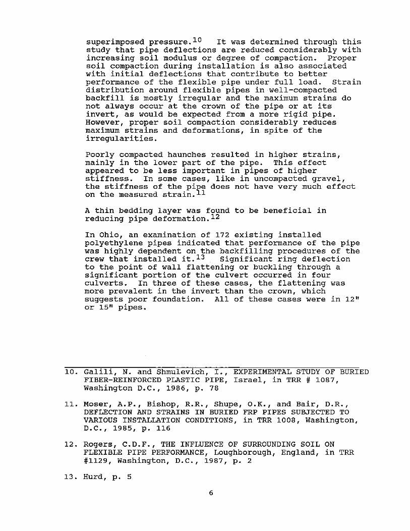
superimposed pressure. 10 It was determined through this study that pipe deflections are reduced considerably with increasing soil modulus or degree of compaction. Proper soil compaction during installation is also associated with initial deflections that contribute to better performance of the flexible pipe under full load. strain distribution around flexible pipes in well-compacted backfill is mostly irregular and the maximum strains do not always occur at the crown of the pipe or at its invert, as would be expected from a more rigid pipe. However, proper soil compaction considerably reduces maximum strains and deformations, in spite of the irregularities.
Poorly compacted haunches resulted in higher strains, mainly in the lower part of the pipe. This effect appeared to be less important in pipes of higher stiffness. In some cases, like in uncompacted gravel, the stiffness of the pi~e does not have very much effect on the measured strain. 1
A thin bedding layer was found to be beneficial in reducing pipe deformation. 12
In Ohio, an examination of 172 existing installed polyethylene pipes indicated that performance of the pipe was highly dependent on the backfilling procedures of the crew that installed it. 13 Significant ring deflection to the point of wall flattening or buckling through a significant portion of the culvert occurred in four culverts. In three of these cases, the flattening was more prevalent in the invert than the crown, which suggests poor foundation. All of these cases were in 1211 or 15 11 pipes.
10. Galili, N. and Shmulevich, I., EXPERIMENTAL STUDY OF BURIED FIBER-REINFORCED PLASTIC PIPE, Israel, in TRR # 1087, Washington D.C., 1986, p. 78
11. Moser, A.P., Bishop, R.R., Shupe, O.K., and Bair, D.R., DEFLECTION AND STRAINS IN BURIED FRP PIPES SUBJECTED TO VARIOUS INSTALLATION CONDITIONS, in TRR 1008, Washington, D.C., 1985, p. 116
12. Rogers, C.D.F., THE INFLUENCE OF SURROUNDING SOIL ON FLEXIBLE PIPE PERFORMANCE, Loughborough, England, in TRR #1129, Washington, D.C., 1987, p. 2
13. Hurd, p. 5
6
D. Selection of Backfill Material
Split backfill of sand and clay, both well compacted, was quite successful. 14 such a backfill might safely be recommended if results of prolonged tests were available.
According to C.D.F. Rogers15 , the type of soil used to surround the pipe has the most influence on its performance. Various uncompacted granular materials were shown to provide good support to the pipe. In order of performance, these included: pea gravel, concrete ballast, washed quarry tailings, and building sand. Relatively large deformations were obtained in silty sand and silty clay. The better, granular materials were more affected by cyclic loads than static loads, whereas the pipes in poorer soils were influenced more by static loads.
Through Rogers' experiments it was determined that the benefit of sidefill compaction was wholly dependent on the soil type. Thorough compaction of a silty clay sidefill in thin (80mm) layers greatly improved the support afforded by this soil. It's performance became comparable to that of the better uncompacted granular soils. Light compaction of a broadly graded soil (concrete ballast) produced a significant improvement in pipe performance. A more uniform soil (pea gravel) proved to be largely unaffected by compaction.
Distortional behavior, consistent with the characteristics of the sidefill, occurred under static load in pipes that were given good support. Elastic recovery of static load deformation was greatest in soils of highest elasticity and in cases where the pipe support was best. The arching behavior of granular soils is important. 16
Specifications usually exclude rocks over 1.5" in diameter from bearing against the pipe. ADS recommends using backfill with no stones larger than 1".
14. Galili, p. 78
15. Rogers, C.D.F., THE INFLUENCE OF SURROUNDING SOIL ON FLEXIBLE PIPE PERFORMANCE, Loughborough, England, in TRR #1129, Washington, D.C., 1987, p. 1
16. Rogers, C.D.F., SOME OBSERVATIONS ON FLEXIBLE PIPE RESPONSE TO LOAD, in TRR #1191, Washington, D.C., 1988, p. 1
7
E. Wall Thickness and Corrugation Shape
In the previously mentioned report from Ohio, it was found that 12" and 15" diameter polyethylene pipes were far more likely to deform in the field than 18" or 24" pipes. This is contrary to classic theory of pipe performance. In the Ohio caselhoweve~ it was most likely a result of the use of much smaller wall thicknesses in the smaller diameter pipes (see the diagram below).
T 1.47" T
12" Oio. 18"0;0. 0 T=0.178" ~ T= 0.065"
--r'" 2.70 "
T IS"Oio.
T=0.091" 24" 010.
T=024" 1.60·
2.93
Fi gure 5 Corrugati on profn~s fore·orrugated: polyethylene pipes. (form IIField Performance of Corrugated Polyethylene Pipe Culverts in Ohioll, TRR 1087, 1986, J.O. Hurd)
In some of the pipes the internal corrugation crests had been stressed by bending moment to the point of tearing apart. In other cases it is possible that flattening of the corrugations occurred and thus allowed more bending. Observations of culverts with severe ring deflection and buckling showed a definite flattening of corrugation profile at points of maximum deflection.
8
TABLE 1 MANUFACTURED SECTION PROPERTIES
Corrugation Depth
NOMINAL MANU- INSIDE DIAMETER FACTURER·
In
4 A 0 P - U H
6 A 0 P U H
8 A 0 P U H
10 A 0 P U H
12 A 0 P U H
15 A 0 P U H
1B A 0 P U H
24 A 0 p U H
30 A 0 p U H
"MANUFACTURERS
A = ADS 0= BlgO U = United Extrusions P = Plastic Service, Inc. H = Hancor
Although the corrugation depth is easily measured, a design relationship is sought that will give a lower bound estimate for h as a fraction of pipe size. Shown in Figure are the data points. IDlh versus 10, taken from Table 1. Here it is observed that lDth = 14 provides the desired relationship, that is,
OUTSIDE AREA MOMENT I AREA DIA. (ORIGINAL) INERTIA I (REVISED)
In In2/1n In4/1n I In2/in l
4.72 0.0533 0.001103 I 0.056 4.86 0.186 0.00211 I 0.060 I
in all cases the corrugation height is greater than VI. of the diameter.
To summarize, this study provides a simple method to accurately determine the section area A using Equation 1. Knowing A, a lower bound estimate for the moment of inertia is given by Equation 2 in which the corrugation height can be taken as 1(14 of the inside diameter.
MANUFACTURED SECTION PROPERTIES FOR CORRUGATED POLYETHYLENE PIPES (AASHTO 294)
(from: M.G. Katona, ALLOWABLE FILL HEIGHTS FOR CORRUGATED POLYETHYLENE PIPE, in TRR #1191, Washington, D.C., 1988)
9
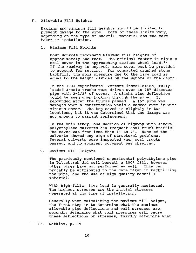
F. Allowable Fill Heights
Maximum and minimum fill heights should be limited to prevent damage to the pipe. Both of these limits vary, depending on the type of backfill material and the care taken in installation.
1. Minimum Fill Heights
Most sources recommend mlnlmum fill heights of approximately one foot. The critical factor in mlnlmum soil cover is the approaching surface wheel load. 17 If the roadway is unpaved, more cover must be provided to account for rutting. For compacted crushed stone backfill, the soil pressure due to the live load is equal to the weight divided by the square of the depth.
In the 1983 experimental Vermont installation, fully loaded 3-axle trucks were driven over an 18" diameter pipe with 2-1/2' of cover. A slight ring deflection could be seen when looking through the pipe. It rebounded after the trucks passed. A 15" pipe was damaged when a construction vehicle backed over it with minimum cover. The top caved in slightly in two locations, but it was determined that the damage was not enough to warrant replacement.
In the Ohio study, one section of highway with several polyethylene culverts had frequent coal truck traffic. The cover was from less than I' to 4'. None of the culverts showed any sign of structural problems. Several culverts were inspected when coal trucks passed, and no apparent movement was observed.
2. Maximum Fill Heights
The previously mentioned experimental polyethylene pipe in pittsburgh did well beneath a lOa' fill, however other pipes have not performed as well. This can probably be attributed to the care taken in backfilling the pipe, and the use of high quality backfill material.
with high fills, live load is generally neglected. The highest stresses are the initial stresses generated at the time of installation.
Generally when calculating the maximum fill height, the first step is to determine what the maximum allowable pipe deflections and wall stresses are, secondly determine what soil pressures will cause these deflections or stresses, thirdly determine what
17. Watkins, p. 15
10
fill height will cause these soil pressures in the soil type to be used, and fourthly to apply a factor of safety.
Two different methods of determining maximum fill heights were examined. The first was based on . laboratory and field testing bK R.K. Watkins, J.M. Dwiggins, and W.E. Altermatt. 1 This study only tested pipes in competent, compacted, granular backfill. A series of formulas was derived for determining the maximum allowable load. It was the assertion of the authors that a pipe can carry much more load through ring compression than flexural strength of the pipe walls. Therefore, as the ring deflects, the pipe cannot carry as much load. The table below relates this deflection to the allowable load P, and the height H of fill that will cause that load, for an 18" CPEP. The height of fill is calculated assuming the unit weight of the soil is 120#/cf.
Table 2
The following is a table of values for IS-in. CPEP.
The values for Hare based on unit weight of soil of 120 Ib/ft3.
The allowable values of H / sfare based on a safety factor of sf = 2.5. Figure 9 is a plot of P as a function of d from the table. The safety factor of sf = 2.5 is higher than necessary if the backfill is good granular soil. On the other hand, if the backfill is marginal, or if the pipe is installed carelessly, a generous safety factor may be justified because of the high cost of repair or replacement.
Allowable loads for flexible pipes at various levels of deflection. (18-inch Corrugated Polyethylene Pipe)
18. Watkins, p. 12
11
The vertical soil strain and the vertical ring deflection must be equal. When soil is compacted more, there is less vertical soil strain under high loads, and therefore less vertical ring deflection. This allows pipes in well compacted soil to carry more load. One graph below shows the pipe deflection, the other shows the soil deflection (the soil density is most important in the immediate area of the pipe). If the two graphs below are scaled to the same x-axis and superimposed on one another, the maximum load (vertical soil pressure) is at the point of intersection, which is where the soil strain is equal to the ring deflection for each soil density. The fill height can then be determined from Table 2 on the previous page.
~ ~. I ----j' ~~.=. -.~.~-'- ~-:- 1 .. ----I u .... ex ... .. 1· ! . I
I I I i
~ o~ __ ~i ____ ~ ____ ~i ____ ~ ____ ~ __ __
o 5 10 IS 20 25
d = a = VERTICAL RI~G D~FLECTION (Percent)
d .. C. = VERTICAL SOIL STP.~.III
FI G URE 6 Vertical pressure at performam:e Umit (dimpUnE at 9 and 3 o'clock) as a function of rinE deflection for II-ln. CPEP.
o 2 3 4
t = VERTICAL SOIL STRAIN (Percent)
FIGURE 7 Hypothetical graphs ohertical soil stress as a function of vertical soil strain for granular soil from compression tests in the laboratory.
Note the difference in scale along the x-axis. The ring deflection must equal the percent soil strain.
For each pipe size, wall shape and soil type, a different set of tables must be established. If good installation is assured, the safety factor of 2.5 may be reduced.
Specifications should establish minimum values for compacted density and should assure competent granular material.
The second method of determining maximum fill heights was a series of tables and charts developed through the use of a computer program called CANOE (Culvert
12
6
Analysis and Design).19 The input data included pipe size, corrugation geometry, backfill soil quality, and design life. Fill heights were calculated, and compared favorably with laboratory test data for all corrugated plastic pipe whose material properties conform to AASHTO specifications. Soil density was assumed to be 120#/ft3 . Formulas were given for interpolations between long and short term fill heights, soil density and quality of backfill material. In most cases, the allowable fill heights may be used with conservative confidence. (The results of this method are outlined in the tables, graphs, and discussion on the next three pages from M.G. Katona's article on allowable fill heights in TRR #1191)19
19. Katona, M.G., ALLOWABLE FILL HEIGHTS FOR CORRUGATED POLYETHYLENE PIPE, in TRR #1191, Washington, D.C., 1988, p. 30
13
Katona
200
180
160
ti 140 \.II I&.
!i 120 c:J iii :
100 ~ II: ~ 80 III C
~ ~ <C
~GOODSOIL o FAIR SOIL
L= LONG TERM S = SHORT TERM X .. EXPERIMENTAL
DESIGN CRITERIA
_ ' what sectional area is required to with-stand a given burial depth?
DESIGN GUIDELINES
The use of Table 3 and the associated Figures 9.10, andll is straightforward as long as the design problem matches the prescribed conditions, that is, soil density is 120 Ib/ft1 , soil quality is either fair or good, and design life is long tenn or short term only. For more generality. the following interpolation schemes are provided to permit design solutions for variations in soil density, soil quality, and design life.
Soil Density
The allowable fill height given in Table~ or, equivalently, in Figures' ,10, andll, is based on a reference soil density, S = 120 lb/ftl. Letting S* denote the actual soil density, then the corresponding fill height H* may be computed as.
S = Short·lann design life (0.05 years) L = Long-tann design Ilfa (SO year.)
14
Fair Quality Soli S L
(ft) (ft)
31.5 12.0 63 .• • 23.7 76.r 35.2
26.3 10.3 51.3 18.2 65.7· 26.0
23.6 U 42.3 15.2 58.S· 21.3
25.0 '" 10.1 40.0 14.8 54.8 19.5
26.0 10.4 38.4 14.4 50.7 1S.3
30.7 12.0 40.6 15.1 SO.5 18.2
' 34.0 12.8 42.3 15.8 SO.5 18.3
-33.4 13.1 40.0 15.2 48.8 17.2
30.2 12.2 35.2 13.8 40.2 15.3
DGOODSOIL
O°FAIRSOIL
TRANSPORTATION RESEARCH RECORD 119}
--SHORT TERM
- LONG TERM
DIAMETER = 4 IN. DIAMETER = 6 IN. DIAMETER = 8 IN. 1 DO ........ -r-...--.,.....,.......-,-,-.-.,
90
80
.1
AREA 1N2"N
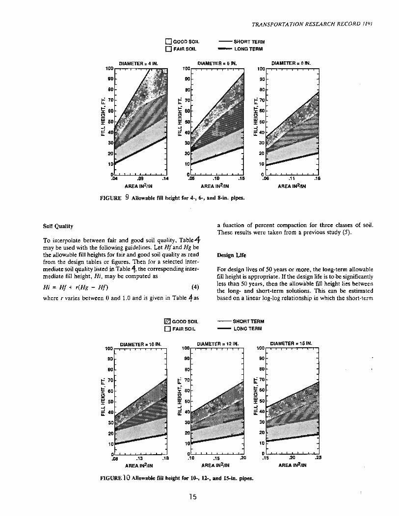
FIGURE 9 Allowable fill height for 4-, 6-, and 8-in. pipes.
Soil Quality
To interpolate between fair and good soil quality, Table4 may be used with the following guidelines. Let Ht and Hg be the allowable fill heights for fair and good soil quality as read from the design tables or figures. Then for a selected intermediate soil quality listed in Table 4, the corresponding intermediate fill height, Hi, may be computed as
Hi = HI + r(Hg - Ht) (4)
where, varies between 0 and 1.0 and is given in Table 4as
~GOODSOIL o FAIR SOIL
a function of percent compaction for three classes of soil. These results were taken from a previous study (5).
Design Life
For design lives of 50 years or more, the long-term allowable fill height is appropriate. If the design life is to be significantly less than 50 years, then the allowable fill height lies between the long- and short-term solutions. This can be estimated based on a linear log-log relationship in which the short-term
--SHORT TERM
- LONG TERM
DIAMETER = 10 IN. DIAMETER = 12 IN. DIAMETER = 151N. 100
.13 .18 .15 .20
AREAIN211N AREAIN211N
FIGURE 10 Allowable fill height for 10-, 12-, and 15-in. pipes.
15
100
90
10
O~~~~~~-L~ .15 .20 .25
AREAIN2/IN
Katona
~GOODSOIL lilll FAIR SOIL
-SHORTTERM
- LONG TERM
DIAMETER = 18 IN. DIAMETER = 24 IN. DIAMETER = 30 IN. 100~~~~~~~~
90
.25 AREAIN2nN
.30
AREA IN211N
90
D~~~~~-L~~ .30 .35 .40
AREAIN211N
FIGURE 11 Allowable nil height for 18-. 14-, and JO.in. pipes.
time period is taken as 0.05 years and the long-term as 50 years. Letting Hs and HI represent the ~Ilowable fill heights ror short- and long-term design periods. and denoting the actual design-life time as t. then the corresponding fill height. HI. is given by
HI = HI (50/t)'" (5)
where the exponent m log(Hs/HI)/3; here the divisor 3 comes from evaluating log(501.05).
Example Design Problems
A 24-in. plastic pipe with a sectional area of 0.3 in.2/in. is to be in service for at least 50 years in a well-graded silty sand
TABLE 4 CORRESPONDENCE OF INTERPOLATION RATIO TO PERCENT COMPACfION
Interpolation Granular Ratio SM
r %
(Fair) 0.0 80
0.25 82
0.50 85
0.75 90
1.00 95 (Good)
SN( = Silty Sand, Well Graded SC = Silty Clayey Sand CL = Clay (No Organic)
Mixed Cohesive SC CL % "-
85 90
87 95
90 100
95 NA
100 NA
16
weighing 130 Ib/ft3 at 85 percent relative compaction. Determine the maximum allowable burial depth .
Referring to Table t lor a SM-85 percent soil condition. it is determined that r = 0.5. Using tbis value in Equation 4 along with HI = 15.2 ft and Hg = 31.5 ft from the long-term fill heights in Table). the temporary result is that HI = 23.4 ft . Readjusting this value for a density of 130 Ib/ft3• the final answer is Hi'" = 21.6 ft.
Now suppose the problem is to be reworked for a 2-year design life. all else remains unchanged. The answer is given by Equation 5. in which HI = 21.6 ft from above. and Hs is determined in the same manner using short-term fill height values to get Hs = 44.3 ft. Thus. the exponent m = 0.104. and the final allowable fill height for a 2-year service life is HI = 30.2 ft .
CONCLUSION
The design results are applicable to all corrugated plastic pipe whose material properties conform to AASHTO specifications (2). whose sectional areas are within limits and whose corrugation height is at least '114 of the diameter. Within the stated restrictions, the allowable fill heights may be used with conservative confidence.
ACKNOWLEDGMENTS
Thanks are extended to the Corrugated Plastic Tubing Association for their support of this study and to William Altermatt of Hancor, Inc .• and James Goddard of Advanced Drainage Systems for their technical guidance.
G. Installation
Even with the extra work involved to keep the polyethylene pipes aligned, the workers say they are easier to work with than steel or concrete pipes. Two men can easily maneuver a 20' long section into a trench.
Movement of the pipe during backfill will create differential loading, causing the culvert to not behave in a theoretical ring compression-deflection manner. The flexibility of the 12 and 15 inch pipes makes them harder to install and more ' suscepti~le to unbalanced bending moments. 20
Splices on the corrugated polyethylene pipes in vermont were done using a two-foot long spin-on coupling. The system did not work because the coupling band would not spin as designed. The coupling had to be screwed onto the in-place pipe for half the band width; then actually turn and thread the 20-foot long 24-inch pipe into the coupling. 21
H. Miscellaneous Information from Published Reports
20. 21. 22. 23. 24. 25. 26.
Due to their flexibility, the ADS pipes did not hold their exact shape when backfilled. The 18 and 24 inch pipes had very slight loss of alignment and some oblong characteristics. When sighting down through the pipeL minor variations in the sides and top could be seen. 2z In general, there was concurrent increase in the horizontal dimension with decrease in the vertical dimension. Deflections at pipe joints were slightly larger than the rest of the culvert. 23
There were no pavement depressions at the locations where the pipe was deflected. Therefore, it was concluded that the deflections occurred during construction. 24
After one year, the cuiverts were subjected to a ten-year flood condition and no significant problems were encountered. 25 In one case, a 24 inch pipe was installed in a low pH, high abrasion location, and was doing fine after 4 years. The previous polymer-coated GCMP deteriorated in less than one year. 26
Damaged ends were observed on seven of the culverts inspected in Ohio. Three were damaged during installation, and four were damaged by vehicles, mowers or
Hurd, p. 5 Houston, p. 9 Houston, p. 12 Hurd, p. 5 Hurd, p. 4 Houston, p. 15 Hurd, p. 4
17
plows. These do not present structural problems, but could affect hydraulic performance. Vulnerable culvert ends should be delineated or protected, or both, especially for shallow installations. There was no apparent deterioration of exposed ends due to uv. 27
According to NCHRP 225, polyethylene can with prolonged exposure be affected by strong oxidizing acids, oils, polar reagents such as detergents, silicones, alcohols, esters, and ketones. PVC can be affected by ketones, esters, aromatic and chlorinated hydrocarbons, and vegetable oils. 28
In Vermont, the HDPE pipes were installed at approximately the same bid price as Asphalt Cement Coated Galvanized Metal Pipes - Around $18jft for 24", $15jft for 18" and 15", and $4.50jft for 6" in 1983.
27. Hurd, p. 4 28. Chambers, p. 15
18
III. COLORADO'S EXPERIENCE
A. Previous Colorado Reports
Two reports have been published in the last couple of years by the CDOH Research Branch on plastic pipes. In the first, "Plastic Pipe Use Under Highways", 1988, no problems occurred with the storm sewers during the 3-1/2 years of service monitored. These pipes were made of poly-vinyl chloride. The diameters ranged from 8 in. to 24 in. The pipe was ribbed on the outside, but smooth on the inside. The cost savings due to reduced material costs were significant. 29
The second report was called, "Evaluation of High-Density Polyethylene pipe." The HDPE pipe in this study was used for rundowns on a steep slope where severe corrosion had b.een a problem with the previous metal pipes. Working on a steep slope, the pipes were much easier to install than other pipes due to their light weight. They have performed well for six years. 30
B. SH 50 Experimental Installation
In March replaced Olathe. the old area.
of 1988 several corroded metal pipes were with plastic pipes on state Highway 50 North of The new pipes were expected to fair better than
ones in the corrosive alkaline environment of the
1. Background Olathe is in the central western slope area of Colorado. The area of this section of highway is fairly flat, but receives a lot of spring run-off from the nearby mountains. The average elevation where the culverts were installed is about 5300 feet. The average daily traffic through this section of highway was about 6000 vehicles, with 14% truck traffic.
At the time of the installation, there were three basic types of smooth-lined plastic pipe available: Corrugated Polyethylene (AASHTO 294 Type S), Ribbed Polyethylene (ASTM F-894 Class 63), and Ribbed PVC (AASHTO approval pending at the time). The pipes selected by the contractor for use on this job were ADS N-12 corrugated polyethylene pipes.
29. Woodham, D., PLASTIC PIPE USE UNDER HIGHWAYS, Report No. CDOH-DTD-R-88-12, Colo. Dept. of Highways, Denver, Co., May 1988, p. iii
30. Woodham, D., EVALUATION OF HIGH-DENSITY POLYETHYLENE PIPE, Report No. CDOH-DTD-R-89-16, Colo. Dept. of Highways, Denver, Co., December 1989, p. iii
19
r. ~/". -
FEDERAL AID PROJECT NO. Fe 050-1 (22) STATE HIGHWAY NO. 50
MONTROSE COUNTY
Figure 12
20
. ... ". ;
Sta. 205 +39.16, End FC 050-1 (22)= -Sta. 701+80 on Proj. NRH 23 F
Sta.100+46.07, Begin FC 050-1 (22)= Stc. 600+69.9 on Proj. RF 050-1 (6)
.P. 81.525
N
c 'h I
-----SCALE IN MILES
2 . Construction
u.s. 50 north of Olathe, approximately 10 miles north of Montrose in western Colorado, was the site of the first installation of polyethylene pipe with smooth interior and corrugated exterior under a state highway. Members of the Research Branch were at the project site on March 18 and 19 to observe the installation of a typical cross culvert. Project FC050-1(22) included culvert installation consisting of nearly 2,000 feet of high-density polyethylene pipe manufactured by Advanced Drainages Systems, Inc. (ADS) .
Pipe diameters for the project ranged from 18 inches to three feet. The installation described in this report involves the construction of a 24-inch cross culvert under the existing u.s. 50 and the future northbound lanes of the roadway. A backhoe excavator, frontloader, and gas-powered compactors were the basic equipment used in the operation. A trench approximately five feet wide was cut into the existing roadway to remove the old asbestos covered corrugated steel pipe. After the appropriate depth was reached, the pipe gradeline was established and the base of the trench was compacted with the gas-powered tampers. The first section of the polyethylene pipe was placed into the trench, and a flared end section was attached. Existing excavated material was placed on both sides of the pipe to a depth of one foot, and compacted. Backfilling continued in this fashion, leaving the other pipe end free for attachment of the next pipe section.
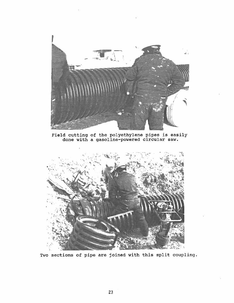
The next pipe section was connected to the first with a split coupling. This coupling had six radial ribs which permitted interlocking three ribs on each of the pipes to be joined. The split coupling had drilled flanges along the split side. High-strength nylon cable ties were used to secure the coupling around the two pipe sections to be joined.
Backfilling and compaction continued without any significant problems. A hydraulic compactor attached to the backhoe was used to compact the soil once the pipe was covered entirely. Density measurements were attempted, but because of the rocky backfill material were deemed erroneous.
The final three sectiqns of pipe for the first cross culvert were placed the following day, extending to the east end of the new roadway right-of-way. One of the twenty-foot pipes had to be cut to obtain a proper fit. A gas-powered circular saw with a mUlti-purpose blade was used to cut the polyethylene pipe without any difficulty.
21
It was noted that handling of this type of pipe was with relative ease. Two men could roll the pipe section off the trailer and into the prepared trench. "Floating" of the pipe sections was not considered to be a particular problem during this installation. Pipe alignment was controlled and maintained quite readily, because the split coupling permitted a certain degree of freedom due to a somewhat loose fit. This on the other hand was one of the concerns of the project engineer. It was thought that this type of connector might leak because of the looseness.
Overall, it was the opinion of the resident engineer and the project engineer that this type of pipe material would provide an excellent alternative to previously used materials in this area of highly corrosive soils. Other advantages are: the light weight, ease of installation, and good hydraulic performance due to the smooth inside surface of the pipe which in some instances may permit using a smaller diameter pipe.
One of the main concerns was the exposed end sections of the culvert system. In this rural section of the state, the main method of controlling weeds in the drainage ditches is by burning them. Although protected by rip-rap, the end sections could sustain some damage if subjected to prolonged high-intensity heat.
(Field Notes by: Werner Hutter)
The gradeline for the new cross-culvert has been established, and soil is being compacted before placing of the pipes.
22
,
Field cutting of the polyethylene pipes is easily done with a gasoline-powered circular saw.
Gasoline-powered compactors are used to obtain a controlled compaction, avoiding "floating" of the pipe sections.
25
No noticeable deflections were seen in any of the pipes after construction.
3. Performance information No noticeable deformations were present in the culverts after construction. After three years , there still does not appear to be any significant deformations within the pipes. Most of the end sections are still in excellent condition, with no evidence of UV deterioration, or any other type of damage. A large amount of seasonal flow with high alkalinity·has gone through the pipes with no visible damage. No cracking was observed. Despite their light weight, the end sections did not move from the proper positions where they were backfilled and attached to the pipe ends with plastic ties. The plastic ties themselves were in good. condition.
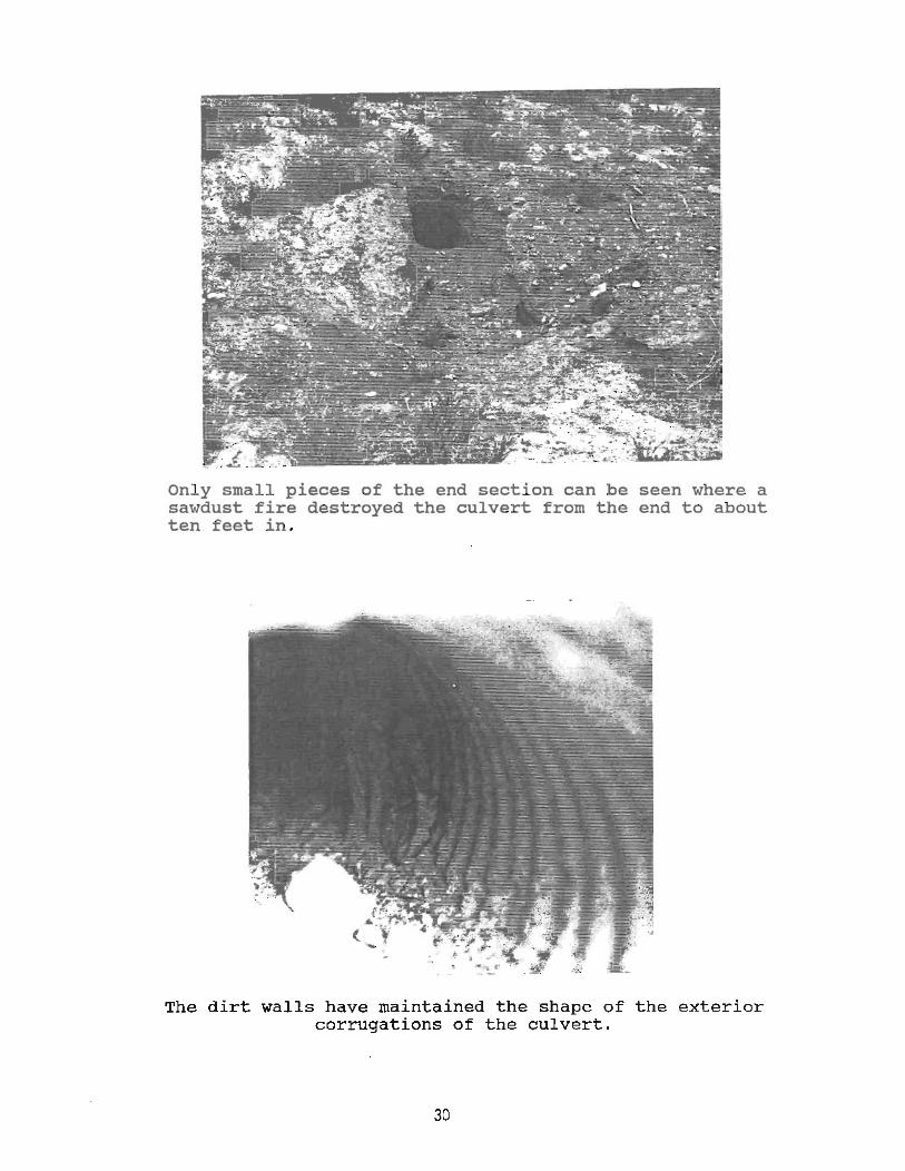
There was a problem with fire in one c:: the culverts. A large amount of sawdust from a nearby saw mill had accumulated in the side ditch and the culvert. In the E.ununer of 1990, this sawdust was somehow ignited, and b~rned in the ditch and about ten feet into the culvert. The soil around the culvert was exposed, but did not collapse. A new segment of pipe was installed in its place. According to the manufacturer, the temperature at which the p~lyethylene pipes melt is 450oF.
26
M_,_ .' ___ "M _____ ._._ .• ___ .,.
These nylon straps were used to attach the end sections. concerns of deterioration or breakage, they remain intact three years. On new installations, end sections are held place with a threaded rod instead of the nylon straps.
The end sections have not moved out of position either, despite their light weight. Some of them, like the one above, still look brand new. The others are only dirty .
27
sometimes the flow in the culverts is very murky and abrasive as in the photo above from October of 1990. At other times, like October of 1988, below, the water is more translucent. The pipes do not show any evidence of deterioration from abrasiveness or chemical action.
28
This culvert was over one-third full after only eight months of service. large flows which sometimes occur in accelerated the deterioration of the
of rocks and sediment This illustrates the these pipes, and metal culverts .
In this flash photo, taken in May of 1991, no deformation can be seen inside the culvert.
29
Only small pieces of the end section can be seen where a sawdust fire destroyed the culvert from the end to about ten feet in .
The dirt walls have maintained the shape of the exterior corrugations of the culvert.
30
Right after the fire, the opposite end of the culvert still contained sawdust several inches thick.
C. COSTS
The average 1990 installed costs per linear foot o f various sizes of reinforced concrete pipes, corrugated steel pipes, and corrugated plastic pipes for the Colorado Department of Highways are shown below:
Table 5: 1990 Average Installed Costs for Culverts
CSP RCP Plastic 12" 21.13 20.39 15.34
15" 20.36 21.52 13.25
18" 19.85 23.05 22.44
24" 22.44 28.30 22.47
30" 28.22 42.30
3 6" 36.04 43 . 94
31
IV. CONCLUSIONS
Corrugated polyethylene pipes are light-weight and easy to install. They are far more resistant to corrosion than metal pipes and probably many concrete pipes. They appear to be more resistant to cracking than concrete pipes. On this Colorado project, there were no problems with deformation of the culverts due to enbankment loads or live loads. Good construction techniques were used.
The carbon black in the culverts does appear to control UV deterioration. It also makes the culverts blend in with dark soils, and does not look bad even in areas of light colored soils. Care should be taken to avoid damage to the end sections from mowers, plows, and other vehicles.
An unsupported plastic pipe will not carry as much load as the much stiffer and thicker concrete pipes. However, with high quality backfill material and proper compaction, very high fills can be supported. Other crucial factors in determining the load carrying capacity are the wall thickness and shape of corrugations. There are tables available which take into account these measurements when determining allowable fill heights.
V. IMPLEMENTATION
Polyethylene pipes are recommended as an alternative to steel or concrete pipes when corrosion, weight, ease of installation, or aesthetics are a concern. Plastic pipe is a current option for use in the 1991 Colorado Standard Specifications for the following items: Culvert Pipe (Section 617), Corrosion Resistant Culverts (Section 624), and Culverts and Sewers (Section 603). In most cases it will be left up to the contractor to determine which pipe material to use. The largest size plastic pipe currently in use by COOT is 36", except for a 42" Spirolite pipe placed inside a deteriorated 60" metal pipe near Dillon.
The minimum depth of cover over the pipe is one fo.ot if compacted well. The allowable maximum enbankment height over the pipe at the time of the experimental installation was 13ft. This has since been increased to 20ft. for PVC, 25ft. for ribbed polyethylene, and 30ft. for corrugated polyethylene.
Specifications should require Class 1 (COOT Standard Spec. 703.08) or better material for backfill. The engineer on the project should make sure that the contractor carefully compacts the material to at least 95% maximum density in lifts no greater than six inches, being extra careful to compact underneath the haunches.
32
In my oplnlon, with careful backfilling and compaction techniques, the fill height may be increased. Since it is difficult to assure that the best construction techniques will be used, a second option is the use of highly granular material, which is less affected by compactive effort. In either case, embankments of at least 50 feet should be possible. Adequate wall thicknesses and corrugations should be specified for the pipes (refer to table 1).
There is an experimental site in Colorado with 58' of fill. This is over a 24" HDPE pipe at SH 133 near Paonia. There is no obvious deformation inside the pipe at this time.
VI. TOPICS TO LOOK AT HORE CLOSELY IN THE FUTURE
Do larger diameter pipes deform more easily? How large of pipes should be allowed? How long do plastic pipes last?
33
BIBLIOGRAPHY
Adams, D.N., Muindi, T., and Selig, E.T., POLYETHYLENE PIPE UNDER HIGH FILL, Univ. of Mass., in TRR #1231, Washington, D.C., 1989
Chambers, R.E., McGrath, T.J., and Heger, F.J., PLASTIC PIPE FOR SUBSURFACE DRAINAGE OF TRANSPORTATION FACILITIES, NCHRP #225, Washington, D.C., October 1980
Galili, N. and Shmulevich, I., EXPERIMENTAL STUDY OF BURIED FIBER-REINFORCED PLASTIC PIPE, Israel, in TRR # 1087, Washington D.C., 1986, p. 78
Hallmark, D.E., and Hendrickson, J.G., EARTH AND TRAFFIC LOADS ON CONDUITS, Portland Cement Association, Chicago, IL, 1967
Houston, E.C., EXPERIMENTAL USE OF CORRUGATED POLYETHYLENE PIPE - CULVERTS AND STORM DRAINS ON ROUTE 12, Vermont Agency of Transportation, Montpelier, VT, 1985
Hurd, J.O., FIELD PERFORMANCE OF CORRUGATED POLYETHYLENE PIPE CULVERTS IN OHIO, Ohio DOT, in TRR #1087, Washington, D.C., 1986
Jacobs, K.M., CULVERT LIFE STUDY, Maine DOT, Bangor, ME, January 1974
Katona, M.G., ALLOWABLE FILL HEIGHTS FOR CORRUGATED POLYETHYLENE PIPE, in TRR #1191, Washington, D.C., 1988
Kurdziel, J.M., CULVERT DURABILITY RATING SYSTEMS, American Pipe Association, in TRR #1191, Washington, D.C., 1988
Kurdziel, J.M., LEAST COST (LIFE CYCLE) ANALYSIS MICROCOMPUTER PROGRAM, in TRR #1191, Washington, D.C., 1988
Moser, A.P., Bishop, R.R., Shupe, O.K., and Bair, D.R., DEFLECTION AND STRAINS IN BURIED FRP PIPES SUBJECTED TO VARIOUS INSTALLATION CONDITIONS, in TRR 1008, Washington, D.C., 1985
Rogers, C.D.F., THE INFLUENCE OF SURROUNDING SOIL ON FLEXIBLE PIPE PERFORMANCE, Loughborough, England, in TRR #1129, Washington, D.C., 1987
Rogers, C.D.F., SOME OBSERVATIONS ON FLEXIBLE PIPE RESPONSE TO LOAD, in TRR #1191, Washington, D.C., 1988
Sharp, K.D., Anderson, L.R., Moser, A.P., and Bishop, R.R., FINITE-ELEMENT ANALYSIS APPLIED TO THE RESPONSE OF BURIED FRP PIPE UNDER VARIOUS INSTALLATION CONDITIONS, in TRR 1008, Washington, D.C., 1985
34
Swanson, H.N., and Donnelly, D.E., PERFORMANCE OF CULVERT MATERIALS IN VARIOUS COLORADO ENVIRONMENTS, Report No. CDOHP&R-R-77-7, Colo. Dept. of Highways, Denver, Co., September, 1977
Watkins, R.K., Dwiggins, J.M., and Altermatt, W.E., STRUCTURAL DESIGN OF BURIED CORRUGATED POLYETHYLENE PIPES, Utah State Univ., in TRR #1129, Washington, D.C., 1987
Woodham, D., EVALUATION OF HIGH-DENSITY POLYETHYLENE PIPE, Report No. CDOH-DTD-R-89-16, Colo. Dept. of Highways, Denver, Co., December 1989
Woodham, D., PLASTIC PIPE USE UNDER HIGHWAYS, Report No. CDOH-DTD-R-88-12, Colo. Dept. of Highways, Denver, Co., May 1988
Zarghamee, M.S., and Tigue, D.B., SOIL-STRUCTURE INTERACTION OF FLEXIBLE PIPE UNDER PRESSURE, in TRR #1087, Washington, D.C., 1986
Research Branch, CULVERT PERFORMANCE AT TEST SITES IN COLORADO, Report No. 68-8, Colo. Dept. of Highways, Denver, Co., August, 1968
35
APPENDIX A
CONCLUSIONS AND SUGGESTED RESEARCH (FROM NCHRP)
NCHRP #225 PLASTIC PIPE FOR SUBSURFACE DRAINAGE OF TRANSPORTATION FACILITIES, October 1980
Chapter Four: Conclusions and Suggested Research Several plastic pipe and corrugated tubing systems are appropriate for subsurface drainage of transportation facilities.
General performance: 1. Chemical resistance - good for natural chemicals and de-icing salts. Prolonged exposure to oils, gasoline, solvents, and strong acids may degrade p"roperties or cause stress cracking if accidental spills occur. 2. Animals, insects and Microorganisms - rodents may chew on corrugated tubing - protect with animal guards. 3. Temperature and thermal effects - relatively large coefficient of thermal expansion must be accounted for in system design. High temperatures increase the flexibility of the pipe, making it more prone to deflection during installations where they are exposed to intense solar radiation. Corrugated tubing is particularly sensitive to this. Plastics may embrittle in cold weather and require special care during installation to prevent impact damage. 4. Handling - light and rugged but some care needed to prevent breakage. 5. Abrasion and wear - Plastic pipe demonstrates good resistance to wear by abrasive slurries, and is frequently used in applications requiring this attribute, such as in the transport of mine tailings. When flow rates are high and capable of transporting large aggregates or when high velocity flow changes direction, special evaluation of abrasion resistance is needed. 6. Resistance to sunlight - at the time of this report, it was not known how resistant to sunlight exposure these pipes were. It was recommended that they be protected. 7. Repair - Plastic pipe can be repaired by cutting and patching, usually with solvent-bonded attachment of patches. Because criteria for quality of repairs are not available, the desired repair method is cutting and replacement with new section. 8.Fire - Plastic pipe burns. It should be protected from direct exposure to fires at its terminus.
36
APPENDIX B
WEIGHT COMPARISONS AND COST COMPARISONS
(from: Houston, E.C., EXPERIMENTAL USE OF CORRUGATED POLYETHYLENE PIPE - CULVERTS AND STORM DRAINS ON ROUTE 12, Vermont Agency of Transportation, Montpelier, VT, 1985, pp. 4 and 14.
37
WEIGHT COMPARISON (Approximate pounds per linear foot)
Inside ADS Corrugated Corrugated Clay or Diameter Plastic Tubing Metal Concrete
18" 6.6 1S.8 131
24" 13.8 19.4 217
COST INFORMATION
Special Provisions called for the ADS pipes as a substitute for steel
culverts at certain locations. The cost of the experimental feature
was higher than what could be expected on the open market. The following
orices were obtained from distributors in the Montpelier area as of Feb., 1985.
Size Cost of Metal Pipes Cost of ADS Pipes
24 inch $11.12/lf. $1S.2S/lf. 18 inch $ 8.7S/If. $ 7.2S/If. 1S inch $ S.3S/If. $ S.70/lf. 6 inch $ 2.00Ilf. $ O.64/lf.
38
APPENDIX C
PROJECT SPECIFICATIONS FOR CDOH PROJECT FC 050-1(22)
39
(
,. (.
REVISION OF SECTION 624 CORROSION RESISTANT CULVERTS
COLORADO PROJECT NO. FC 050-1(22)
Oct. 21, 1987
Section 624 is hereby added to the Standard Specifications and shall include the following:
DESCRIPTION'
624 .01 This work shall consist of furnishing and installing corrosion resistant culvert pipe in accordance with these specifications and in reasonably close conformity with the lines and grades shown on the plans or as established.
624 .02 Katerials specifications as
Abbreviations
CSP
Bit. Co. CSP
ASB . Bo. CSP
CAP
PCSP-both sides
PCSP-one side
RCP
NRC?
PVC
PE
MATERIALS
shall meet the requirements shown on the plans and the indicated below for the type of culvert pipe furnished.
Description
Corrugated Steel Pipe
Bituminous Coated Corrugated Steel Pipe
Asbestos Bonded Corrugated Steel Pipe
Corrugated Aluminum Pipe
Precoated Corrugated Steel Pipe coated on both sides with 0.010 in. min.
Precoated Corrugated Steel Pipe coated on one side
Reinforced Concrete Pipe-Type of Cement to be specified
Non-reinforced Concrete Pipe-Type of Cement to be specified
Polyvinyl Chloride
Specification
707.02
707.03
707.03
707. 06
AASHTO K 245 and K 246
AASHTO K 245 and K 246
706.02
706.01
ASTM F 794*
Polyethylene*** AASHTO M 294** (Smooth-lined interior)
-continued-
40
c
t
\,
-2-REVISION OF SECTION 624
CORROSION RESISTANT CULVERTS COLORADO PROJECT NO. FC 050-1(22)
*J-K Perma Loc meets ASTK F 794.
oct. 21, 1987
**PE-ADS by Advanced Drainage Systems meets AASHTO K 294.
***Spirolite, Class 40, as manufactured by Spiral Engineered Systems, 4094 Blue Ridge Industrial Parkway, Norcross, Georgia 30071, is an acceptable polyethylene pipe. Local contact is Dick Sorenson, Intermountain Utility Sales, 3280 South Wadsworth Blvd., Denver, Colorado 80227 (303) 980-1312.
All PCSP culvert shall be tested for holidays or other damage to coating after fabrication, and all damage so found shall be repaired in an approved manner.
Connecting bands and end sections shall receive the same corrosion protection as the pipe with which they are used. Coatings conforming to the requirements of Revisions of Sections 706 and 707 will be permitted as applicable.
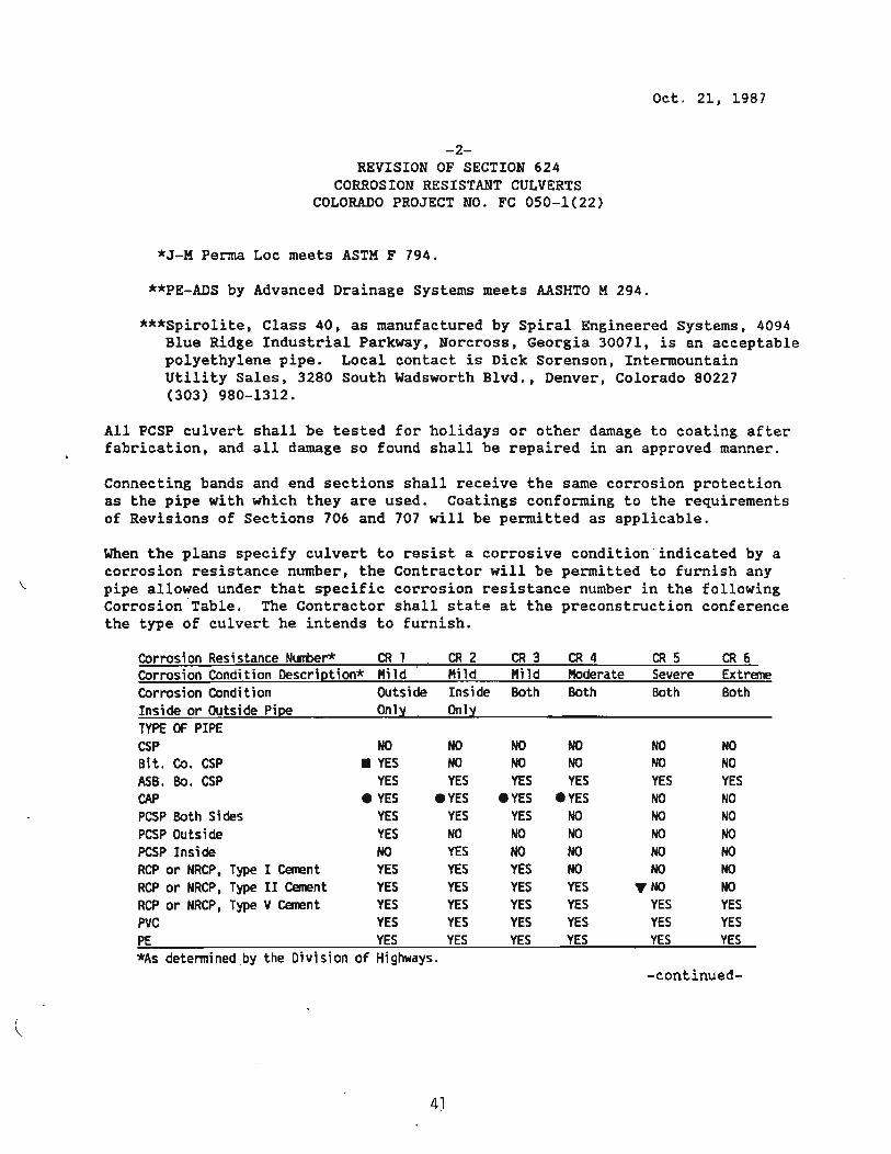
When the plans specify culvert to resist a corrosive condition " indicated by a corrosion resis~ance number, the Contractor will be permitted to furnish any pipe allowed under that specific corrosion resistance number in the following Corrosion "Table. The Contractor shall state at the preconstruction conference the type of culvert he intends to furnish.
Corrosion Resistance Number* CRl CR2 CR 3 CR 4 CRS CR6 Corrosion Condition Descrietion* Mild Mild MHd Moderate Severe Extreme Corrosion Condition Outside Inside Both Both Both Both Inside or Outside Pi~ Onl~ Onl:t TYPE OF PIPE CSP NO NO NO NO NO NO Bit. Co. CSP • YES NO NO NO NO NO ASB. Bo. CSP YES YES YES YES YES YES CAP eYES eYES eYES eYES NO NO PCSP Both Sides YES YES YES NO NO NO pcsp Outside YES NO NO NO NO NO PCSP Inside NO YES NO NO NO NO RCP or NRCP, Type I Cement YES YES YES NO NO NO RCP or NRCP, Type II Cement YES YES YES YES ~NO NO RCP or NRCP, Type V Cement YES YES YES YES YES YES PVC YES YES YES YES YES YES PE YES YES YES YES YES YES *As detennined " b~ the Division of Highwa~s.
-continued-
4)
(
-3-REVISION OF SECTION 624
CORROSION RESISTANT CULVERTS COLORADO PROJECT NO. FC 050-1(22)
oct. 21. 1987
.RCP or NRCP made with Type II cement having maximums of 5~ C3A and 25~ (C4AF+2C3A) may be used for all corrosion conditions except CR-6 if approved by the Central Laboratory .
• Coated Steel Structural PLate Pipe of equal or greater diameter, conforming to Section 510 of the Standard Specifications, may be substituted for Bit. Co. CSP at no additional cost to the project .
• Aluminum Alloy Structural Plate Pipe of equal or greater diameter, conforming to Section 510 of the Standard Specifications, may be substituted for CAP at no additional cost to the project. -
COUSTRUCTIOU REQUIREMENTS
624.03 Installation shall conform to the requirements of Section 603 or section 510 as applicable.
Joining and installation of plastic pipe shall conform to ASTM 02321 and the manufacturer's recommendations.
HETMOD OF HEASUREMENT
624.04 Corrosion resistant culvert pipe will be measured by linear foot of length "L" as shown on the plans, completed and accepted. Length "L" shall include end sections when required.
BASIS OF PAYMENT
624.05 The accepted quantities of corrosion resistant culvert pipe will be paid for at the contract unit price per linear foot for the specified size and corrosion number.
Payment will be made under:
Pay Item Pay Unit Inch Culvert Pipe (CR 6) Linear Foot
Structure excavation and structure backfill will be measured and paid for in accordance with Section 206. Quantities are based on the use of plastic pipe. If the Contractor elects to use larger sizes of CSP or RCP, structure excavation and backfill will be paid based on the quantities shown in the plans.
42
PATCHING DETAIL (For Culvert Replacement and Remoyol)