Optics 2015; 4(1): 1-12 Published online April 16, 2015 (http://www.sciencepublishinggroup.com/j/optics) doi: 10.11648/j.optics.20150401.11 ISSN: 2328-7780 (Print); ISSN: 2328-7810 (Online) Polymer Optic Technology Askari Mohammad Bagher 1 , Bahrampour Mohammad Reza 2 1 Department of Physics, Payame Noor University, Tehran, Iran 2 Department of metallurgy, Shahid Dadbin institute of Kerman 171, Vocational and Technical University, Kerman, Iran Email address: [email protected] (Askari M. B.) To cite this article: Askari Mohammad Bagher, Bahrampour Mohammad Reza. Polymer Optic Technology. Optics. Vol. 4, No. 1, 2015, pp. 1-12. doi: 10.11648/j.optics.20150401.11 Abstract: A polymer is a large molecule, or macromolecule, composed of many repeated subunits. Because of their broad range of properties, [1] both synthetic and natural polymers play an essential and ubiquitous role in everyday life.[2] Polymers range from familiar synthetic plastics such as polystyrene to natural biopolymers such as DNA and proteins that are fundamental to biological structure and function. Polymers, both natural and synthetic, are created via polymerization of many small molecules, known as monomers. Their consequently large molecular mass relative to small molecule compounds produces unique physical properties, including toughness, viscoelasticity, and a tendency to form glasses and semi crystalline structures rather than crystals. In this article we will investigate the role of polymers in optics and photonics and we will cite examples of polymers used in optics. Keywords: Polymer Optic, Polymer Crystal, P-oled, Solar Cell, Optical, Fiber, Organic Polymer, Polymer Lasers, Optical Lenses 1. Introduction Polymer physics is the field of physics that studies polymers, their fluctuations, mechanical properties, as well as the kinetics of reactions involving degradation and polymerization of polymers and monomers respectively.[3][4][5][6].While it focuses on the perspective of condensed matter physics, polymer physics is originally a branch of statistical physics. Polymer physics and polymer chemistry are also related with the field of polymer science, where this is considered the applicative part of polymers. Polymers are large molecules and thus are very complicated for solving using a deterministic method. Yet, statistical approaches can yield results and are often pertinent, since large polymers (i.e., polymers with a large number of monomers) are describable efficiently in the thermodynamic limit of infinitely many monomers (although the actual size is clearly finite).Thermal fluctuations continuously affect the shape of polymers in liquid solutions, and modeling their effect requires using principles from statistical mechanics and dynamics. As a corollary, temperature strongly affects the physical behavior of polymers in solution, causing phase transitions, melts, and so on. The statistical approach for polymer physics is based on an analogy between a polymer and either a Brownian motion, or other type of a random walk, the self- avoiding walks. The simplest possible polymer model is presented by the ideal chain, corresponding to a simple random walk. Experimental approaches for characterizing polymers are also common, using Polymer characterization methods, such as size exclusion chromatography, Viscometer, Dynamic light scattering, and Automatic Continuous Online Monitoring of Polymerization Reactions (ACOMP)[7][8] for determining the chemical, physical, and material properties of polymers. These experimental methods also helped the mathematical modeling of polymers and even for a better understanding of the properties of polymers. A crystal or crystalline solid is a solid material whose constituents, such as atoms, molecules or ions, are arranged in a highly ordered microscopic structure, forming a crystal lattice that extends in all directions. In addition, macroscopic single crystals are usually identifiable by their geometrical shape, consisting of flat faces with specific, characteristic orientations. The scientific study of crystals and crystal formation is known as crystallography. The process of crystal formation via mechanisms of crystal growth is called crystallization or solidification. The word crystal is derived from the Ancient Greek word (krustallos), meaning both “ice” and “rock crystal”,[9]Examples of large
Transcript
Optics 2015; 4(1): 1-12 Published online April 16, 2015 (http://www.sciencepublishinggroup.com/j/optics) doi: 10.11648/j.optics.20150401.11 ISSN: 2328-7780 (Print); ISSN: 2328-7810 (Online)
Polymer Optic Technology
Askari Mohammad Bagher1, Bahrampour Mohammad Reza
2
1Department of Physics, Payame Noor University, Tehran, Iran 2Department of metallurgy, Shahid Dadbin institute of Kerman 171, Vocational and Technical University, Kerman, Iran
To cite this article: Askari Mohammad Bagher, Bahrampour Mohammad Reza. Polymer Optic Technology. Optics. Vol. 4, No. 1, 2015, pp. 1-12. doi: 10.11648/j.optics.20150401.11
Abstract: A polymer is a large molecule, or macromolecule, composed of many repeated subunits. Because of their broad range of properties, [1] both synthetic and natural polymers play an essential and ubiquitous role in everyday life.[2] Polymers range from familiar synthetic plastics such as polystyrene to natural biopolymers such as DNA and proteins that are fundamental to biological structure and function. Polymers, both natural and synthetic, are created via polymerization of many small molecules, known as monomers. Their consequently large molecular mass relative to small molecule compounds produces unique physical properties, including toughness, viscoelasticity, and a tendency to form glasses and semi crystalline structures rather than crystals. In this article we will investigate the role of polymers in optics and photonics and we will cite examples of polymers used in optics.
Polymer physics is the field of physics that studies polymers, their fluctuations, mechanical properties, as well as the kinetics of reactions involving degradation and polymerization of polymers and monomers respectively.[3][4][5][6].While it focuses on the perspective of condensed matter physics, polymer physics is originally a branch of statistical physics. Polymer physics and polymer chemistry are also related with the field of polymer science, where this is considered the applicative part of polymers. Polymers are large molecules and thus are very complicated for solving using a deterministic method. Yet, statistical approaches can yield results and are often pertinent, since large polymers (i.e., polymers with a large number of monomers) are describable efficiently in the thermodynamic limit of infinitely many monomers (although the actual size is clearly finite).Thermal fluctuations continuously affect the shape of polymers in liquid solutions, and modeling their effect requires using principles from statistical mechanics and dynamics. As a corollary, temperature strongly affects the physical behavior of polymers in solution, causing phase transitions, melts, and so on. The statistical approach for polymer physics is based on an analogy between a polymer and either a
Brownian motion, or other type of a random walk, the self-avoiding walks. The simplest possible polymer model is presented by the ideal chain, corresponding to a simple random walk. Experimental approaches for characterizing polymers are also common, using Polymer characterization methods, such as size exclusion chromatography, Viscometer, Dynamic light scattering, and Automatic Continuous Online Monitoring of Polymerization Reactions (ACOMP)[7][8] for determining the chemical, physical, and material properties of polymers. These experimental methods also helped the mathematical modeling of polymers and even for a better understanding of the properties of polymers.
A crystal or crystalline solid is a solid material whose constituents, such as atoms, molecules or ions, are arranged in a highly ordered microscopic structure, forming a crystal lattice that extends in all directions. In addition, macroscopic single crystals are usually identifiable by their geometrical shape, consisting of flat faces with specific, characteristic orientations. The scientific study of crystals and crystal formation is known as crystallography. The process of crystal formation via mechanisms of crystal growth is called crystallization or solidification. The word crystal is derived from the Ancient Greek word (krustallos), meaning both “ice” and “rock crystal”,[9]Examples of large
2 Askari Mohammad Bagher and Bahrampour Mohammad Reza: Polymer Optic Technology
crystals include snowflakes, diamonds, and table salt. Most inorganic solids are not crystals but polycrystals, i.e. many microscopic crystals fused together into a single solid. Examples of polycrystals include most metals, rocks, ceramics, and ice. A third category of solids is amorphous solids, where the atoms have no periodic structure whatsoever. Examples of amorphous solids include glass, wax, and many plastics. The scientific definition of a "crystal" is based on the microscopic arrangement of atoms inside it, called the crystal structure. A crystal is a solid where the atoms form a periodic arrangement. (Quasicrystals are an exception, see below.)Not all solids are crystals. For example, when liquid water starts freezing, the phase change begins with small ice crystals that grow until they fuse, forming a polycrystalline structure. In the final block of ice, each of the small crystals (called "crystallites" or "grains") is a true crystal with a periodic arrangement of atoms, but the whole polycrystalline does not have a periodic arrangement of atoms, because the periodic pattern is broken at the grain boundaries. Most macroscopic inorganic solids are polycrystalline, including almost all metals, ceramics, ice, rocks, etc. Solids that are neither crystalline nor polycrystalline, such as glass, are called amorphous solids, also called glassy, vitreous, or no crystalline. These have no periodic order, even microscopically. There are distinct differences between crystalline solids and amorphous solids: most notably, the process of forming a glass does not release the latent heat of fusion, but forming a crystal does. A crystal structure (an arrangement of atoms in a crystal) is characterized by its unit cell, a small imaginary box containing one or more atoms in a specific spatial arrangement. The unit cells are stacked in three-dimensional space to form the crystal. The symmetry of a crystal is constrained by the requirement that the unit cells stack perfectly with no gaps. There are 219 possible crystal symmetries, called crystallographic space groups. These are grouped into 7 crystal systems, such as cubic crystal system (where the crystals may form cubes or rectangular boxes, such as halite shown at right) or hexagonal crystal system (where the crystals may form hexagons, such as ordinary water ice).
Polycrystalline materials are solids that are composed of many crystallites of varying size and orientation. Crystallites are also referred to as grains. They are small or even microscopic crystals and form during the cooling of many materials. Their orientation can be random with no preferred direction, called random texture, or directed, possibly due to growth and processing conditions. Fiber texture is an example of the latter. The areas where crystallite grains meet are known as grain boundaries. Most inorganic solids are polycrystalline, including all common metals, many ceramics, rocks and ice. The extent to which a solid is crystalline (crystalline) has important effects on its physical properties.[10] Sulfur, while usually polycrystalline, may also occur in other allotropic forms with completely different properties.[11] Although crystallites are referred to as grains, powder grains are
different, as they can be composed of smaller polycrystalline grains themselves.[12]
Polymorphism is the ability of a substance to exist in several different amorphous modifications. It is analogous to the polymorphism of crystalline materials. Many amorphous substances can exist with different amorphous characteristics (e.g. polymers). However, polymorphism requires two distinct amorphous states with a clear, discontinuous (first-order) phase transition between them. When such a transition occurs between two stable liquid states, a polymorphic transition may also be referred to as a liquid–liquid phase transition. [13]
Even though amorphous materials exhibit no long-range periodic atomic ordering, there is still significant and varied local structure at inter-atomic length scales (see structure of liquids and glasses). Different local structures can produce amorphous phases of the same chemical composition with different physical properties such as density. In several cases sharp transitions have been observed between two different density amorphous states of the same material. Amorphous ice is one important example (see also examples below).[14] Several of these transitions (including water) are expected to end in a second critical point. Polymorphism may apply to all amorphous states, i.e. glasses, other amorphous solids, super cooled liquids, ordinary liquids or fluids. A liquid–liquid transition however, is one that occurs only in the liquid state (red line in the phase diagram, top right). In this article liquid–liquid transitions are defined as transitions between two liquids of the same chemical substance. Elsewhere the term liquid–liquid transition may also refer to the more common transitions between liquid mixtures of different chemical composition. The stable liquid state unlike most glasses and amorphous solids, is a thermodynamically stable equilibrium state. Thus new liquid–liquid or fluid-fluid transitions in the stable liquid (or fluid) states are more easily analyses than transitions in amorphous solids where arguments are complicated by the non-equilibrium, non-ergodic nature of the amorphous state. Liquid–liquid transitions were originally considered by Rapport in 1967 in order to explain high pressure melting curve maxima of some liquid metals.[16] Rapport's theory requires the existence of a melting curve maximum in polymorphic systems. One physical explanation for polymorphism is the existence of a double well inter-atomic pair potential (see lower right diagram). It is well known that the ordinary liquid–gas critical point appears when the inter-atomic pair potential contains a minimum. At lower energies (temperatures) particles trapped in this minimum condense into the liquid state. At higher temperatures however, these particles can escape the well and the sharp definition between liquid and gas is lost. Molecular modeling has shown that addition of a second well produces an additional transition between two different liquids (or fluids) with a second critical point.[16]Polymorphism has also been observed in organic compounds, such as liquid triphenyl phosphate at temperatures about 200 K.[17][18][19][20]
Optics 2015; 4(1): 1-12 3
Polymorphism is also a potentially important area in pharmaceutical science. The amorphous form of a drug typically has much better aqueous solubility (cf. the analogous crystalline form) but the actual local structure in an amorphous pharmaceutical can be different, depending on the method used to form the amorphous phase.
2. Crystallization of Polymers
Crystallization of polymers is a process associated with partial alignment of their molecular chains. These chains fold together and form ordered regions called lamellae, which compose larger spherical structures named spherulites.[21] Polymers can crystallize upon cooling from the melt, mechanical stretching or solvent evaporation. Crystallization affects optical, mechanical, thermal and chemical properties of the polymer. The degree of crystalline is estimated by different analytical methods and it typically ranges between 10 and 80%, thus crystallized polymers are often called "semi crystalline". The properties of semi crystalline polymers are determined not only by the degree of crystalline, but also by the size and orientation of the molecular chains. Polymers are composed of long molecular chains which form irregular, entangled coils in the melt. Some polymers retain such a disordered structure upon freezing and thus convert into amorphous solids. In other polymers, the chains rearrange upon freezing and form partly ordered regions with a typical size of the order 1 micrometer.[22] Although it would be energetically favorable for the polymer chains to align parallel, such alignment is hindered by the entanglement. Therefore, within the ordered regions, the polymer chains are both aligned and folded. Those regions are therefore neither crystalline nor amorphous and are classified as semi crystalline. Examples of semi-crystalline polymers are linear polyethylene (PE), polyethylene terephthalate (PET), polytetrafluoroethylene (PTFE) or are tactic polypropylene (PP). [23]
Whether or not polymers can crystallize depends on their molecular structure – presence of straight chains with regularly spaced side groups facilitates crystallization. For example, crystallization occurs much easier in is tactic than in the atactic polypropylene form. A tactic polymers crystallize when the side groups are very small, as in polyvinyl and don't crystallize in case of large substituent's like in rubber or silicones.[23]
2.1. Nucleation
Lamellae form during crystallization from the melt. The arrow shows the direction of temperature gradient. [24]
Nucleation starts with small, nanometer-sized areas where as a result of heat motion some chains or their segments occur parallel. Those seeds can either dissociate, if thermal motion destroys the molecular order, or grow further, if the grain size exceeds a certain critical value.[24][23]
Apart from the thermal mechanism, nucleation is strongly affected by impurities, dyes, plasticizers, fillers and other
additives in the polymer. This is also referred to as heterogeneous nucleation. This effect is poorly understood and irregular, so that the same additive can promote nucleation in one polymer, but not in another. Many of the good nucleating agents are metal salts of organic acids, which themselves are crystalline at the solidification temperature of the polymer solidification. [24]
2.2. Crystal Growth from the Melt
Schematic model of a spherules. Black arrows indicate direction of molecular alignment
Crystal growth is achieved by the further addition of folded polymer chain segments and only occurs for temperatures below the melting temperature Tm and above the glass transition temperature Tg. Higher temperatures destroy the molecular arrangement and below the glass transition temperature, the movement of molecular chains is frozen. [25] Nevertheless, secondary crystallization can proceed even below Tg, in the time scale of months and years. This process affects mechanical properties of the polymers and decreases their volume because of a more compact packing of aligned polymer chains. [23][26]
The chains interact via various types of the van der Waals forces. The interaction strength depends on the distance between the parallel chain segments and it determines the mechanical and thermal properties of the polymer. [27]
The growth of the crystalline regions preferably occurs in the direction of the largest temperature gradient and is suppressed at the top and bottom of the lamellae by the amorphous folded parts at those surfaces. In the case of a strong gradient, the growth has a unidirectional, dendritic character.[28] However, if temperature distribution is isotropic and static then lamellae grow radially and form larger quasi-spherical aggregates called spherulites. Spherulites have a size between about 1 and 100 micrometers[22] and form a large variety of colored patterns (see, e.g. front images) when observed between crossed polarizer's in an optical microscope, which often include the "Maltese cross" pattern and other polarization phenomena caused by molecular alignment within the individual lamellae of a spherullite.[21][24][23]
2.3. Crystallization by Stretching
The arrangement of the molecule chains upon crystallization by stretching. [23]
The above mechanism considered crystallization from the melt, which is important for injection molding of plastic components. Another type of crystallization occurs upon extrusion used in making fibers and films. In this process, the polymer is forced through, e.g., a nozzle that creates tensile stress which partially aligns its molecules. Such alignment can be considered as crystallization and it affects the material properties. For example, the strength of the fiber is greatly increased in the longitudinal direction, and optical properties show large anisotropy along and perpendicular to the fiber axis. Such anisotropy is more enhanced in presence of rod-
4 Askari Mohammad Bagher and Bahrampour Mohammad Reza: Polymer Optic Technology
like fillers such as carbon annotates, compared to spherical fillers.[28]Polymer strength is increased not only by extrusion, but also by blow molding, which is used in the production of plastic tanks and PET bottles.[27] Some polymers which do not crystallize from the melt, can be partially aligned by stretching.[29]Some elastomers which are amorphous in the unstrained state undergo rapid crystallization upon stretching.
2.4. Crystallization from Solution
Polymers can also be crystallized from a solution or upon evaporation of a solvent. This process depends on the degree of dilution: in dilute solutions, the molecular chains have no connection with each other and exist as a separate polymer coils in the solution. Increase in concentration which can occur via solvent evaporation, induces interaction between molecular chains and a possible crystallization as in the crystallization from the melt. [30] Crystallization from solution may result in the highest degree of polymer crystalline. For example, highly linear polyethylene can form platelet-like single crystals with a thickness on the order 10–20 nm when crystallized from a dilute solution. The crystal shape can be more complex for other polymers, including hollow pyramids, spirals and multilayer dendritic structures. [21]
A very different process is precipitation; it uses a solvent which dissolves individual monomers but not the resulting polymer. When a certain degree of polymerization is reached, the polymerized and partially crystallized product precipitates out of the solution. The rate of crystallization can be monitored by a technique which selectively probes the dissolved fraction, such as nuclear magnetic resonance. [29]
2.5. Confined Crystallization
When polymers crystallize from an isotropic, bulk of melt or concentrated solution, the crystalline lamellae (10 to 20 nm in thickness) are typically organized into a spherulitic morphology as illustrated above. However when polymer chains are confined in a space with dimensions of a few tens of nanometers, comparable to or smaller than the lamellar crystal thickness or the radius of gyration, nucleation and growth can be dramatically affected. As an example, when a polymer crystallizes in a confined ultrathin layer, the isotropic spherulitic organization of lamellar crystals is hampered and confinement can produce unique lamellar crystal orientations.[30] Sometimes the chain alignment is parallel to the layer plane and the crystals are organized as ‘‘on-edge’’ lamellae. In other cases, "in-plane" lamellae with chain orientation perpendicular to the layers are observed. The unique crystal orientation of confined polymers imparts anisotropic properties. In one example the large, in-plane polymer crystals reduce the gas permeability of nanolayered films by almost 2 orders of magnitude. [30]
2.6. Density Measurements
Crystalline areas are generally more densely packed than amorphous areas. This results in a higher density, up to 15%
depending on the material. For example, polyamide 6 (nylon) has crystalline density ρc = 1.24 g/cm3 and amorphous density ρa = 1.08 g/cm3). However, moisture which is often present in the sample does affect this type of measurement. [25]
2.7. Calorimetric
Additional energy is released upon melting a semi crystalline polymer. This energy can be measured with differential scanning calorimetric and compared with that released upon melting of the standard sample of the same material with known crystallization degree.[25][31]
2.8. X-ray Diffraction
Regular arrangement of atoms and molecules produce sharp diffraction peaks whereas amorphous regions result in broad halos. The diffraction pattern of polymers usually contains a combination of both. Degree of crystalline can be estimated by integrating the relative intensities of the peaks and halos.[25]
2.9. Infrared Spectroscopy (IR)
Infrared absorption or reflection spectra from crystalline polymers contain additional peaks which are absent in amorphous materials with the same composition. These signals may originate from deformation vibrations of the regular arrangement of molecular chains. From the analysis of these bands, the degree of crystalline can be estimated. [25]
2.10. Nuclear Magnetic Resonance (NMR)
Crystalline and amorphous areas differ by the mobility of protons. The latter can be monitored through the line shape of NMR signals and used to estimate the degree of crystalline. [25]
2.11. Kinetics of Polymer Crystalline
The methods used to determine the degree of crystalline can be incorporated over time to measure the kinetics of crystallization. The most basic model for polymer crystallization kinetics comes from Hoffman Nucleation Theory. The crystallization process of polymers does not always obey simple chemical rate equations. Polymers can crystallize through a variety of different regimes and unlike simple molecules; the polymer crystal lamellae have two very different surfaces. The two most prominent theories in polymer crystallization kinetics are the Avrami equation and Lauritzen-Hoffman Growth Theory. [32]
3. Properties of Semi Crystalline
Polymers
3.1. Thermal and Mechanical Properties
Below their glass transition temperature, amorphous polymers are usually hard and brittle because of the low mobility of their molecules. Increasing the temperature
Optics 2015; 4(1): 1-12 5
induces molecular motion resulting in the typical rubber-elastic properties. A constant force applied to a polymer at temperatures above Tg results in a viscoelastic deformation, i.e., the polymer begins to creep. Heat resistance is thus given for amorphous polymers just below the glass transition temperature. [33]
Relatively strong intermolecular forces in semi crystalline polymers prevent softening even above the glass transition temperature. Their elastic modulus changes significantly only at high (melting) temperature.[3]It also depends on the degree of crystalline: higher crystalline results in a harder and more thermally stable, but also more brittle material, whereas the amorphous regions provide certain elasticity and impact resistance.[11][14] Another characteristic feature of semi crystalline polymers is strong anisotropy of their mechanical properties along the direction of molecular alignment and perpendicular to it.[34]
Plastics are viscoelastic materials meaning that under applied stress, their deformation increases with time (creep). The elastic properties of plastics are therefore distinguished according to the time scale of the testing to short-time behavior (such as tensile test which lasts minutes), shock loading, the behavior under long-term and static loading, as well as the vibration-induced stress.[35]
3.2. Optical Properties
Semicrystalline polymers are usually opaque because of light scattering on the numerous boundaries between the crystalline and amorphous regions. The density of such boundaries is lower and thus the transparency is higher either for low (amorphous polymer) or high (crystalline) degree of crystalline.[14] For example, ataxic polypropylene is usually amorphous and transparent while syndiotactic polypropylene, which has crystalline ~50%, is opaque.[36] Crystalline also affects dyeing of polymers: crystalline polymers are more difficult to stain than amorphous ones because the dye molecules penetrate much easier through amorphous regions.[37]
Polycarbonates (PC), known by the trademarked names Lexan, Makrolon and others, are a particular group of thermoplastic polymers. They are easily worked, molded, and thermoformed. Because of these properties, polycarbonates find many applications. Polycarbonates do not have a unique resin identification code and are identified as other, 7. Items made from polycarbonate can contain the precursor monomer biphenyl A (BPA).Polycarbonates received their name because they are polymers containing carbonate groups (–O–(C=O)–O–). A balance of useful features including temperature resistance, impact resistance and optical properties position polycarbonates between commodity plastics and engineering plastics. Polycarbonate is a durable material. Although it has high impact-resistance, it has low scratch-resistance and so a hard coating is applied to polycarbonate eyewear lenses and polycarbonate exterior automotive components. The characteristics of polycarbonate are quite like those of polymethyl methacrylate (PMMA, acrylic), but polycarbonate is stronger and usable over a
greater temperature range. Polycarbonate is highly transparent to visible light, with better light transmission than many kinds of glass.
Polycarbonate has a glass transition temperature of about 147 °C (297 °F),[6] so it softens gradually above this point and flows above about 155 °C (311 °F).[38] Tools must be held at high temperatures, generally above 80 °C (176 °F) to make strain- and stress-free products. Low molecular mass grades are easier to mold than higher grades, but their strength is lower as a result. The toughest grades have the highest molecular mass, but are much more difficult to process.
Unlike most thermoplastics, polycarbonate can undergo large plastic deformations without cracking or breaking. As a result, it can be processed and formed at room temperature using sheet metal techniques, such as bending on a brake. Even for sharp angle bends with a tight radius, heating may not be necessary. This makes it valuable in prototyping applications where transparent or electrically non-conductive parts are needed, which cannot be made from sheet metal. Note that PMMA/Plexiglas, which is similar in appearance to polycarbonate, is brittle and cannot be bent at room temperature.
4. Main Transformation Techniques for
Polycarbonate Resins
Extrusion into tubes, rods and other profiles including multiwall extrusion with cylinders (calendars) into sheets (0.5–20 mm (0.020–0.787 in)) and films (below 1 mm (0.039 in)), which can be used directly or manufactured into other shapes using thermoforming or secondary fabrication techniques, such as bending, drilling, routing, laser cutting etc.
5. Electronic Components
Polycarbonate is mainly used for electronic applications that capitalize on its collective safety features. Being a good electrical insulator and having heat-resistant and flame-retardant properties, it is used in various products associated with electrical and telecommunications hardware. It can also serve as a dielectric in high-stability capacitors.[39] However, commercial manufacture of polycarbonate capacitors mostly stopped after sole manufacturer Bayer AG stopped making capacitor-grade polycarbonate film at the end of year 2000.[40]
6. Construction Materials
The second largest consumer of polycarbonates is the construction industry, e.g. for dome lights, flat or curved glazing, and sound walls.
6.1. Data Storage
A major application of polycarbonate is the production of
6 Askari Mohammad Bagher and Bahrampour Mohammad Reza: Polymer Optic Technology
Compact Discs, DVDs, and Blue-ray Discs. These discs are produced by injection molding polycarbonate into a mold cavity that has on one side a metal stamper containing a negative image of the disc data, while the other mold side is a mirrored surface. Typical products of sheet/film production include applications in advertisement (signs, displays, poster protection).[38]
6.2. Automotive, Aircraft, and Security Components
In the automotive industry, injection-molded polycarbonate can produce very smooth surfaces that make it well-suited for sputter deposition or evaporation deposition of aluminum without the need for a base-coat. Decorative bezels and optical reflectors are commonly made of polycarbonate. Due to its low weight and high impact resistance, polycarbonate is the dominant material for making automotive headlamp lenses. However, automotive headlamps require outer surface coatings because of its low scratch resistance and susceptibility to ultra violet degradation (yellowing). The use of polycarbonate in automotive applications is limited to low stress applications. Stress from fasteners, plastic welding and molding render polycarbonate susceptible to stress corrosion cracking when it comes in contact with certain accelerants such as salt water and plastisol. It can be laminated to make bullet-proof "glass", although "bullet-resistant" is more accurate for the thinner windows, such as are used in bullet-resistant windows in automobiles. The thicker barriers of transparent plastic used in teller's windows and barriers in banks are also polycarbonate. So-called "theft-proof" large plastic packaging for smaller items, which cannot be opened by hand, is uniformly made from polycarbonate. The cockpit canopy of the F-22 Raptor jet fighter is made from a piece of high optical quality polycarbonate, and is the largest piece of its type formed in the world.[41][42]South African security companies have launched the 'transparent burglar bar' under a variety of retail names, made from polycarbonate.[43]
6.3. Niche Applications
Polycarbonate, being a versatile material with attractive processing and physical properties, has attracted myriad smaller applications. The use of injection molded drinking bottles, glasses and food containers is common, but the use of BPA in the manufacture of polycarbonate has stirred serious controversy (see Potential hazards in food contact applications), leading to development and use of "BPA-free" plastics in various formulations. Polycarbonate is commonly used in eye protection, as well as in other projectile-resistant viewing and lighting applications that would normally indicate the use of glass, but require much higher impact-resistance. Polycarbonate lenses also protect the eye from UV light. Many kinds of lenses are manufactured from polycarbonate, including automotive headlamp lenses, lighting lenses, sunglass/eyeglass lenses, swimming goggles and SCUBA masks, and safety
glasses/goggles/visors including visors in sporting helmets/masks and police riot gear. Windscreens in small motorized vehicles are commonly made of polycarbonate, such as for motorcycles, ATVs, golf carts, and small planes and helicopters. The light weight of polycarbonate as opposed to glass has led to development of electronic display screens that replace glass with polycarbonate, for use in mobile and portable devices. Such displays include newer e-ink and some LCD screens, though CRT, plasma screen and other LCD technologies generally still require glass for its higher melting temperature and its ability to be etched in finer detail. As more and more governments are restricting the use of glass in pubs and clubs [44] due to the increased incidence of glassing, polycarbonate glasses [45] are becoming popular for serving alcohol because of their strength, durability, and glass-like feel. Other miscellaneous items include durable, lightweight luggage, MP3/digital audio player cases, ocarinas, computer cases, riot shields, instrument panels, tea light candle containers and blender jars. Many toys and hobby items are made from polycarbonate parts, e.g. fins, gyro mounts, and fly bar locks for use with radio-controlled helicopters. [46] Standard Polycarbonate resins are not suitable for long term exposure to UV radiation. To overcome this primary resin can have UV Stabilizers added. These grades are sold as UV Stabilized Polycarbonate to Injection Molding and Extrusion companies. Other applications including Polycarbonate sheet may have the anti-UV layer added as a special coating or a co extrusion for enhanced weathering resistance. Polycarbonate is also used as a printing substrate for nameplate and other forms of industrial grade under printed products. The polycarbonate provides a barrier to wear, the elements, and fading.
6.4. Phones
Some major Smartphone manufacturers use polycarbonate. Nokia has used polycarbonate in their phones starting with the N9's anybody case in 2011. This practice continues with various phones in the Lumia series. Samsung has started using polycarbonate with Galaxy S III's battery cover in 2012. This practice continues with various phones in the Galaxy series. Apple has started using polycarbonate with iPhone 5c's unibody case in 2013.
6.5. Organic Polymer
Compared to carbon-based polymers, polydimethylsiloxane (PDMS) polymers:
● Have more open, more flexible molecular chains – are less rigid.
● Have the ability to form much longer chains without solidifying.
● Have stronger, more stable bonds and are more resistant to harsh environmental, processing, and operating conditions.
● Are more flexible and flowable at low temperatures, and do not break down under high temperatures.
Optics 2015; 4(1): 1-12 7
● Are able to align their organic substituents more effectively at interfaces; can more easily “connect” with other materials and formulation ingredients.
● Flow more easily and are capable of forming thinner films.
6.6. Some Important Differences Between Silicon and
Carbon
● The silicon atom is larger than the carbon atom. Its bonds are longer and more flexible with wider bond angles.
● Silicon is less electronegative than carbon (1.8 for silicon vs. 2.5 for carbon); it is able to give up more of its electrons to form strong, energetic bonds with other elements.
● Silicon only forms single bonds, not multiple bonds (single bonds are more stable and harder to break than double or triple bonds).
6.7. Organic Polymer in Lasers
Fig. 1. (Organic polymer in lasers) (This is a brief guide to some aspects of
the literature of solid-state organic lasers. These organic lasers use dye-
doped organic polymer gain media and they are also known as dye-doped
polymer lasers. It should be noted that these lasers have been demonstrated
to lase under optical excitation that can be accomplished either by the use of
a pump laser or by the use of non-laser (incoherent) means. In all cases this
pumping, or excitation, represents an indirect electrical mode of excitation.
Non-laser, electrically indirect, pumping for this class of lasers was first
demonstrated in 1967.) www.tunablelasers.com
The dye-doped polymer laser has a long history and its development came in various stages that began with the basic discoveries of 1967 and continued, via the development of improved gain media, until the event of high-performance polymer narrow-line width laser oscillators.[47]
6.8. Organic Polymer in P-oled
OLEDs are solid-state devices composed of thin films of organic molecules that create light with the application of electricity. OLEDs can provide brighter, crisper displays on electronic devices and use less power than conventional light-emitting diodes (LEDs) or liquid crystal displays (LCDs) used today. OLEDs are made by placing thin films of organic (carbon based) materials between two conductors. When electrical current is applied, a bright light is emitted. The OLED materials emit light and do not require a backlight (unlike LCDs). Each pixel is a small light-emitting diode, in
fact. OLEDs emit light they do not require a backlight and so are thinner and more efficient than LCD displays (which do require a white backlight).In this paper we investigate the characteristics of OLED[48].
Fig. 2. (Interferogram showing single-longitudinal-mode emission from
Note that these images were originally recorded on black and white silver-
halide film and have been colored to approximate the emission of the laser.)
The basic principle of operation of P-OLEDs is as follows: ● An amorphous film of the P-OLED material is
sandwiched between two electrodes forming the anode and cathode on a transparent substrate
● Electronic charges are transported and injected into the polymer from the electrodes: electrons from the cathode, and ‘holes’ from the anode
● The electrons and holes ‘capture each other’ through electrostatic interaction
● Radioactive recombination of electron and hole generates light
● The wavelength of this emitted light depends on the band gap of the polymer used.
P-OLEDs can be used to produce light of a very wide range of wavelengths – including light outside the visible range – by modifying the precise structure of the polymer used.
The structure of a basic P-OLED display device can be extremely simple, consisting of a sandwich containing:
● A transparent conducting anode with a large work function. Indium tin oxide (ITO) is commonly used, coated on a substrate
● A conducting polymer layer which transports and injects holes into the active layers (Hole Injection / Transport Layer)
● A thin organic interlayer material sometimes referred to primer layer developed by CDT to improve efficiency and lifetime
● A thin light emitting polymer layer less than 100nm thick (emissive Layer)
● A metallic cathode with a low work function, such as a barium/aluminum bi-layer.
8 Askari Mohammad Bagher and Bahrampour Mohammad Reza:
Fig. 3. (Organic polymer in p-oled) www.cdtltd.co.uk
The simplicity and solution process abilitymaterials together make P-OLEDs an excitingapplications from small mobile displaysscreen TVs and large area lighting panels.
6.9. Technology Developments
Device efficiencies have been improved of polymer and device modifications. Thepolymer (LEP) has been modified photoluminescence quantum yield (PLQY),have been improved by adding a thinbetween the hole transport layer material (typicallyPSS) and the LEP. This additional layer is commonlyto as an interlayer/primer layer (IL).
Fig. 4. (p-oled) (P-OLEDs can be used to produce light
of wavelengths – including light outside the visible range
precise structure of the polymer used.)www.cdtltd.co.uk
The LEP has been designed to exhibitmobility than whole mobility. The interlayer/primerthe other hand, is designed with hole transportpossesses a higher hole mobility than electronelectron transport is favored in the LEP, whileis favored in the primer layer. The net effectelectron and hole charges accumulate at theand away from either the cathode or anode.charge balance within the devices can be
Askari Mohammad Bagher and Bahrampour Mohammad Reza: Polymer Optic Technology
www.cdtltd.co.uk.
ability of P-OLED exciting prospect for
displays though to large
via a combination The light emitting to increase its
(PLQY), while devices thin polymeric layer
(typically PEDOT-commonly referred
light of a very wide range
range – by modifying the
www.cdtltd.co.uk
exhibit higher electron interlayer/primer layer, on
transport in mind and electron mobility, i.e.
while hole transport effect of this is that the LEP: iL interface anode. In this way, obtained, exaction
(electron-hole pair in the maximized, and exaction quenchinganode is avoided.
Using this approach we Quantum Efficiencies (EQE) ofcolors from blue to deep red.[49]
6.10. Organic Polymer in Solar
A polymer solar cell is a typewith polymers, large moleculesunits that produce electricityphotovoltaic effect. Polymer solarcells (also called "plastic solarthin film solar cell; others includesilicon solar cell.Most commerciala refined, highly purified siliconmaterial used in the manufacturecomputer chips (wafer silicon).solar cells and their complex interest in alternative technologiesbased devices, polymer solar cellsimportant for small autonomousdisposable and inexpensive toprinted electronics), flexible, customizablelevel and potentially have less adversePolymer solar cells also havetransparency, suggesting applicationsflexible electronics, etc. An example1. The disadvantages of polymerthey offer about 1/3 of the efficiencyexperience substantial photochemical
Polymer solar cells inefficiencycombined with their promise ofefficiency[53] made them a research. As of 2015, polymerachieve over 10% efficiency via
Fig. 5. (Flexible, organic solar cells -
and resources in making devices like organic
printed .) phys.org
Polymer solar cells usually consistblocking layer on top of anconductive glass followed by electronacceptor (in the case of bulk
echnology
excited state) formation is quenching by either cathode or
have demonstrated External of 5% or above for a range of
[49]
Solar Cell
type of flexible solar cell made molecules with repeating structural electricity from sunlight by the
solar cells include organic solar solar cells"). They are one type of include the more stable amorphous
commercial solar cells are made from silicon crystal, similar to the
manufacture of integrated circuits and silicon). The high cost of these silicon
production process generated technologies. Compared to silicon-
cells are lightweight (which is autonomous sensors), potentially
to fabricate (sometimes using customizable on the molecular adverse environmental impact.
have the potential to exhibit applications in windows, walls,
example device is shown in Fig. polymer solar cells are also serious:
efficiency of hard materials, and photochemical degradation[50] inefficiency and stability problems,[51]
of low costs[52] and increased popular field in solar cell
polymer solar cells were able to via a tandem structure.[54]
- IMRE's polymer can help save costs
organic solar cells and next generation
consist of an electron- or hole-an indium tin oxide (ITO) electron donor and an electron heterojunction solar cells), a
Optics 2015; 4(1): 1-12 9
hole or electron blocking layer, and metal electrode on top. The nature and order of the blocking layers – as well as the nature of the metal electrode – depends on whether the cell follows a regular or an inverted device architecture. In an inverted cell, the electric charges exit the device in the opposite direction as in a normal device because the positive and negative electrodes are reversed. Inverted cells can utilize cathodes out of a more suitable material; inverted OPVs enjoy longer lifetimes than regularly structured OPVs, but they typically don’t reach efficiencies as high as regular OPVs.[55]
In bulk heterojunction polymer solar cells, light generates excitons. Subsequent charge separation in the interface between an electron donor and acceptor blend within the device’s active layer. These charges then transport to the device’s electrodes where the charges flow outside the cell, perform work and then re-enter the device on the opposite side. The cell's efficiency is limited by several factors, especially non-geminate recombination. Hole mobility leads to faster conduction across the active layer.[56][57]
Polymer solar cells have many intrinsic advantages, such as their light weight, flexibility, and low material and manufacturing costs. Recently, polymer tandem solar cells have attracted significant attention due to their potential to achieve higher performance than single cells [58] Organic photovoltaic's are made of electron donor and electron acceptor materials rather than semiconductor p-n junctions. The molecules forming the electron donor region of organic PV cells, where exciton electron-hole pairs are generated, are generally conjugated polymers possessing delocalized π electrons that result from carbon p orbital hybridization. These π electrons can be excited by light in or near the visible part of the spectrum from the molecule's highest occupied molecular orbital (HOMO) to the lowest unoccupied molecular orbital (LUMO), denoted by a π -π* transition. The energy bandgap between these orbitals determines which wavelength(s) of light can be absorbed. Unlike in an inorganic crystalline PV cell material, with its band structure and delocalized electrons, exactions in organic photovoltaic's are strongly bound with energy between 0.1 and 1.4 eV. This strong binding occurs because electronic wave functions in organic molecules are more localized, and electrostatic attraction can thus keep the electron and hole together as an exaction. The electron and hole can be dissociated by providing an interface across which the chemical potential of electrons decreases. The material that absorbs the photon is the donor, and the material acquiring the electron is called the acceptor. the polymer chain is the donor and the fullerene is the acceptor. Even after dissociation, the electron and hole may still be joined as a "geminate pair", and an electric field is then required to separate them. The electron and hole must be collected at contacts. If charge carrier mobility is insufficient, the carriers will not reach the contacts, and instead recombine at trap sites or remain in the device as undesirable space charges that oppose the flow of new carriers. The latter problem can occur if electron and hole motilities are not matched. In that case,
space-charge limited photocurrent (SCLP) hampers device performance. Organic photovoltaic's can be fabricated with an active polymer and a fullerene-based electron acceptor. Illumination of this system by visible light leads to electron transfer from the polymer to a fullerene molecule. As a result, the formation of a photo induced quasiparticle, or polar on (P+), occurs on the polymer chain and the fullerene becomes a radical anion (C−60). Polarons are highly mobile and can diffuse away.
7. Polymer Used in Optical Lenses
Polymer lenses can be produced cost-effectively and have a low weight. Because of the convenient design freedom they are found in numerous markets, such as Automotive & Mobility, Lighting & Energy, Health Care & Life Science and Optical Measurement & Machine Vision.
Fig. 6. (Complex optical designs previously limited to glass optics are now
possible in plastic, including this lens which has multiple optical surfaces
with various ) www.laserfocusworld.com
8. Polymer Used in Optical Fiber
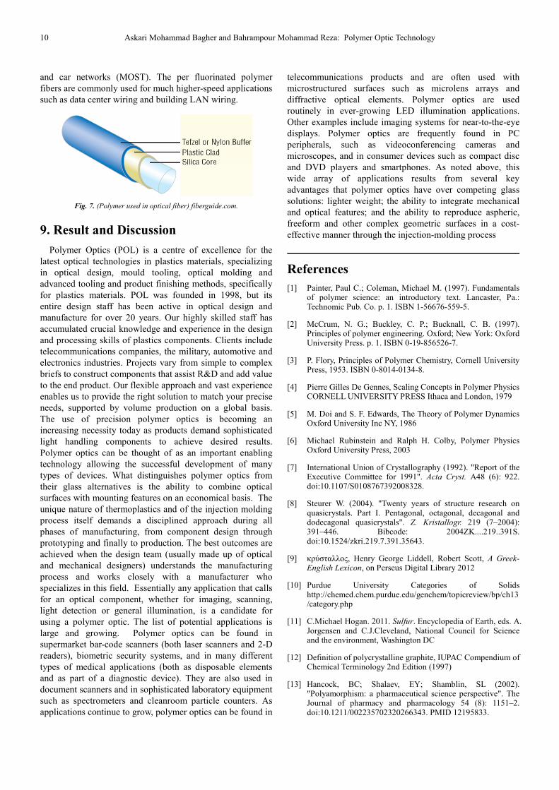
Plastic optical fiber (POF) (or Polymer optical fiber) is an optical fiber which is made out of plastic. Traditionally PMMA (acrylic) is the core material, and fluorinated polymers are the cladding material. Since the late 1990s however, much higher-performance POF based on per fluorinated polymers (mainly polyperfluorobutenylvinylether) has begun to appear in the marketplace. In large-diameter fibers, 96% of the cross section is the core that allows the transmission of light. Similar to traditional glass fiber, POF transmits light (or data) through the core of the fiber. The core size of POF is in some cases 100 times larger than glass fiber. POF has been called the "consumer" optical fiber because the fiber and associated optical links, connectors, and installation are all inexpensive. Due to the attenuation and distortion characteristics of the traditional PMMA fibers are commonly used for low-speed, short-distance (up to 100 meters) applications in digital home appliances, home networks, industrial networks (PROFIBUS, PROFINET),
10 Askari Mohammad Bagher and Bahrampour Mohammad Reza: Polymer Optic Technology
and car networks (MOST). The per fluorinated polymer fibers are commonly used for much higher-speed applications such as data center wiring and building LAN wiring.
Fig. 7. (Polymer used in optical fiber) fiberguide.com.
9. Result and Discussion
Polymer Optics (POL) is a centre of excellence for the latest optical technologies in plastics materials, specializing in optical design, mould tooling, optical molding and advanced tooling and product finishing methods, specifically for plastics materials. POL was founded in 1998, but its entire design staff has been active in optical design and manufacture for over 20 years. Our highly skilled staff has accumulated crucial knowledge and experience in the design and processing skills of plastics components. Clients include telecommunications companies, the military, automotive and electronics industries. Projects vary from simple to complex briefs to construct components that assist R&D and add value to the end product. Our flexible approach and vast experience enables us to provide the right solution to match your precise needs, supported by volume production on a global basis. The use of precision polymer optics is becoming an increasing necessity today as products demand sophisticated light handling components to achieve desired results. Polymer optics can be thought of as an important enabling technology allowing the successful development of many types of devices. What distinguishes polymer optics from their glass alternatives is the ability to combine optical surfaces with mounting features on an economical basis. The unique nature of thermoplastics and of the injection molding process itself demands a disciplined approach during all phases of manufacturing, from component design through prototyping and finally to production. The best outcomes are achieved when the design team (usually made up of optical and mechanical designers) understands the manufacturing process and works closely with a manufacturer who specializes in this field. Essentially any application that calls for an optical component, whether for imaging, scanning, light detection or general illumination, is a candidate for using a polymer optic. The list of potential applications is large and growing. Polymer optics can be found in supermarket bar-code scanners (both laser scanners and 2-D readers), biometric security systems, and in many different types of medical applications (both as disposable elements and as part of a diagnostic device). They are also used in document scanners and in sophisticated laboratory equipment such as spectrometers and cleanroom particle counters. As applications continue to grow, polymer optics can be found in
telecommunications products and are often used with microstructured surfaces such as microlens arrays and diffractive optical elements. Polymer optics are used routinely in ever-growing LED illumination applications. Other examples include imaging systems for near-to-the-eye displays. Polymer optics are frequently found in PC peripherals, such as videoconferencing cameras and microscopes, and in consumer devices such as compact disc and DVD players and smartphones. As noted above, this wide array of applications results from several key advantages that polymer optics have over competing glass solutions: lighter weight; the ability to integrate mechanical and optical features; and the ability to reproduce aspheric, freeform and other complex geometric surfaces in a cost-effective manner through the injection-molding process
References
[1] Painter, Paul C.; Coleman, Michael M. (1997). Fundamentals of polymer science: an introductory text. Lancaster, Pa.: Technomic Pub. Co. p. 1. ISBN 1-56676-559-5.
[2] McCrum, N. G.; Buckley, C. P.; Bucknall, C. B. (1997). Principles of polymer engineering. Oxford; New York: Oxford University Press. p. 1. ISBN 0-19-856526-7.
[3] P. Flory, Principles of Polymer Chemistry, Cornell University Press, 1953. ISBN 0-8014-0134-8.
[4] Pierre Gilles De Gennes, Scaling Concepts in Polymer Physics CORNELL UNIVERSITY PRESS Ithaca and London, 1979
[5] M. Doi and S. F. Edwards, The Theory of Polymer Dynamics Oxford University Inc NY, 1986
[6] Michael Rubinstein and Ralph H. Colby, Polymer Physics Oxford University Press, 2003
[7] International Union of Crystallography (1992). "Report of the Executive Committee for 1991". Acta Cryst. A48 (6): 922. doi:10.1107/S0108767392008328.
[8] Steurer W. (2004). "Twenty years of structure research on quasicrystals. Part I. Pentagonal, octagonal, decagonal and dodecagonal quasicrystals". Z. Kristallogr. 219 (7–2004): 391–446. Bibcode: 2004ZK....219..391S. doi:10.1524/zkri.219.7.391.35643.
[9] κρύσταλλος, Henry George Liddell, Robert Scott, A Greek-English Lexicon, on Perseus Digital Library 2012
[10] Purdue University Categories of Solids http://chemed.chem.purdue.edu/genchem/topicreview/bp/ch13/category.php
[11] C.Michael Hogan. 2011. Sulfur. Encyclopedia of Earth, eds. A. Jorgensen and C.J.Cleveland, National Council for Science and the environment, Washington DC
[12] Definition of polycrystalline graphite, IUPAC Compendium of Chemical Terminology 2nd Edition (1997)
[13] Hancock, BC; Shalaev, EY; Shamblin, SL (2002). "Polyamorphism: a pharmaceutical science perspective". The Journal of pharmacy and pharmacology 54 (8): 1151–2. doi:10.1211/002235702320266343. PMID 12195833.
Optics 2015; 4(1): 1-12 11
[14] Mishima, O.; Calvert, L. D.; Whalley, E. (1985). "An apparently 1st-order transition between two amorphous phases of ice induced by pressure". Nature 314 (6006): 76. Bibcode:1985Natur.314...76M. doi:10.1038/314076a0.
[15] Rapoport, E. (1967). "Model for melting curve maxima at high pressure". J. Chem. Phys. 46 (2891): 1–5. Bibcode:1967JChPh..46.2891R. doi:10.1063/1.1841150.
[16] Franzese, G.; Malescio, G; Skibinsky, A; Buldyrev, SV et al. (2001). "Generic mechanism for generating a liquid–liquid phase transition". Nature 409 (6821): 692–5. arXiv:cond-mat/0102029. Bibcode: 2001Natur.409..692F. doi:10.1038/35055514. PMID 11217853.
[17] K. J. Rao (2002). Structural chemistry of glasses. Elsevier. p. 120. ISBN 0-08-043958-6.
[18] Ha, Alice; Cohen, Itai; Zhao, Xiaolin; Lee, Michelle et al. (1996). "Supercooled Liquids and Polyamorphism†". The Journal of Physical Chemistry 100: 1. doi:10.1021/jp9530820.
[19] Poole, P. H. (1997). "Polymorphic Phase Transitions in Liquids and Glasses". Science 275 (5298): 322. doi:10.1126/science.275.5298.322.
[20] Paolo M. Ossi (2006). Disordered materials: an introduction. Springer. p. 65. ISBN 3-540-29609-3.
[21] Charles E. Carraher, Raymond Benedict Seymour (2003). Seymour/Carraher's polymer chemistry. CRC Press. pp. 43–45. ISBN 0-8247-0806-7.
[22] Linda C. Sawyer, David T. Grubb, Gregory F. Meyers (2008). Polymer microscopy. Springer. p. 5. ISBN 0-387-72627-6.
[23] G. W. Ehrenstein, Richard P. Theriault (2001). Polymeric materials: structure, properties, applications. Hanser Verlag. pp. 67–78. ISBN 1-56990-310-7.
[24] Georg Menges, Edmund Haberstroh, Walter Michaeli, Ernst Schmachtenberg: Plastics Materials Science Hanser Verlag, 2002, ISBN 3-446-21257-4
[25] GW Becker, Ludwig Bottenbruch, Rudolf Binsack, D. Braun: Engineering Thermoplastics. Polyamides. (in German) Hanser Verlag, 1998 ISBN 3-446-16486-3
[26] Wilbrand Woebcken, Klaus Stöckhert, HBP Gupta: Plastics Encyclopedia. (in German) Hanser Verlag, 1998, ISBN 3-446-17969-0
[27] Wolfgang Weissbach: Materials science and materials testing. Vieweg + Teubner Verlag, 2007, ISBN 3-8348-0295-6
[28] Nilesh Patil, Luigi Balzano, Giuseppe Portale and Sanjay Rastogi (2010). "A study on the chain - particle interaction and aspect ratio of nanoparticles on structure development of a linear polymer". Macromolecules 43 (16): 6749. Bibcode:2010 MaMol..43.6749P. doi:10.1021/ma100636v.
[29] J. Lehmann (1966). "The observation of the crystallization of high polymer substances from the solution by nuclear magnetic resonance". Colloid & Polymer Science 212 (2): 167–168. doi:10.1007/BF01553085.
[30] Wang, Haopeng; Jong K. Keum; Anne Hiltner; Eric Baer; Benny Freeman; Artur Rozanski; Andrzej Galeski (6 February 2009). "Confined Crystallization of Polyethylene Oxide in Nanolayer Assemblies". Science 323 (5915): 757–760. Bibcode:2009Sci...323..757W. doi:10.1126/science.1164601.
[31] Gottfried W. Ehrenstein, Gabriela Riedel, Pia Trawiel: Practice of thermal analysis of plastics. Hanser Verlag, 2003, ISBN 3-446-22340-1
[32] Paul C. Painter, Michael M. Coleman (1997). "8". Fundamentals of Polymer Science An Introductory Text, Second Edition. CRC Press.
[33] Joachim Nentwig: Plastic films (in German) Hanser Verlag, 2006, ISBN 3-446-40390-6
[34] Martin Bonnet: Plastics in engineering applications: properties, processing and practical use of polymeric materials. (in German) Vieweg+Teubner Verlag, 2008 ISBN 3-8348-0349-9
[35] James F. Shackelford (2009). Introduction to Materials Science for Engineers. Prentice Hall. pp. 168–169. ISBN 0-13-601260-4.
[36] Andrew J. Peacock, Allison R. Calhoun (2006). Polymer chemistry: properties and applications. Hanser Verlag. pp. 286–287. ISBN 1-56990-397-2.
[37] Ágnes Tímár-Balázsy, Dinah Eastop (1998). Chemical principles of textile conservation. Butterworth-Heinemann. p. 11. ISBN 0-7506-2620-8.
[38] "Polycarbonate". city plastics. Retrieved 2013-12-18.
[39] Volker Serini "Polycarbonates" in Ullmann's Encyclopedia of Industrial Chemistry, Wiley-VCH, Weinheim, 2000. doi:10.1002/14356007.a21_207
[40] Wima (capacitor manufacturer) on discontinuation of polycarbonate capacitors and recommended substitutes. 2012-6-2.
[41] Egress technicians keep raptor pilots covered. Pacaf.af.mil. Retrieved on 2011-02-26.
[42] F-22 Cockpit. Globalsecurity.org (2008-01-21). Retrieved on 2011-02-26.
[43] M. Parvin and J. G. Williams (1975). "The effect of temperature on the fracture of polycarbonate". Journal of Materials Science 10 (11): 1883. Bibcode:1975JMatS..10.1883P. doi:10.1007/BF00754478.
[50] Joachim Luther, Michael Nast, M. Norbert Fisch, Dirk Christoffers, Fritz Pfisterer, Dieter Meissner, Joachim Nitsch "Solar Technology" 2002, Wiley-VCH, 2008 Weinheim. doi:10.1002/14356007.a24_369
12 Askari Mohammad Bagher and Bahrampour Mohammad Reza: Polymer Optic Technology
[51] Jørgensen, M., K. Norrman, and F.C. Krebs (2008). "Stability/degradation of polymer solar cells". Solar Energy Materials and Solar Cells 92 (7): 686. doi:10.1016/j.solmat.2008.01.005.
[52] Po, Riccardo; Carbonera, Chiara; Bernardi, Andrea; Tinti, Francesca; Camaioni, Nadia (2012). "Polymer- and carbon-based electrodes for polymer solar cells: Toward low-cost, continuous fabrication over large area". Solar Energy Materials and Solar Cells 100: 97. doi:10.1016/j.solmat.2011.12.022.
[53] Scharber, M. C.; Mühlbacher, D.; Koppe, M.; Denk, P.; Waldauf, C.; Heeger, A. J.; Brabec, C. J. (2006). "Design Rules for Donors in Bulk-Heterojunction Solar Cells—Towards 10 % Energy-Conversion Efficiency". Advanced Materials 18 (6): 789. doi:10.1002/adma.200501717.
[54] You, Jingbi; Dou, Letian; Yoshimura, Ken; Kato, Takehito; Ohya, Kenichiro; Moriarty, Tom; Emery, Keith; Chen, Chun-Chao (5 February 2013). "A polymer tandem solar cell with 10.6% power conversion efficiency". Nature Communications 4. doi:10.1038/ncomms2411.
[55] Zyga, Lisa. "Inverted polymer solar cell efficiency sets world record". Phys.org. Retrieved 18 February 2015.
[56] Pivrikas, A.; Sariciftci, N. S.; Juška, G.; Österbacka, R. (2007). "A review of charge transport and recombination in polymer/fullerene organic solar cells". Progress in Photovoltaics: Research and Applications 15 (8): 677. doi:10.1002/pip.791.
[57] Tessler, Nir; Preezant, Yevgeni; Rappaport, Noam; Roichman, Yohai (2009). "Charge Transport in Disordered Organic Materials and Its Relevance to Thin-Film Devices: A Tutorial Review". Advanced Materials 21 (27): 2741. doi:10.1002/adma.200803541.