Polymer Optical Fiber Termination WithUse of Liquid Nitrogen
Marcelo Vaca Pereira Ghirghi, Vladimir P. Minkovich, and Armando Garcia Villegas
Abstract— In this letter, we present a new method for prepar-ing perpendicular end faces in polymer optical fibers on a base ofpolymethyl metacrylate. Initially, a scratch is circumferentiallymade around the fiber. Then, the fiber is briefly cooled withliquid nitrogen or liquid nitrogen vapor, and subsequently bentover a curved surface to obtain a perpendicular fracture. Wedemonstrate a significant improvement in insertion loss for suchfaces, which are comparable with those of polished fibers.
Index Terms— Optical fibers, optical fiber testing, opticallosses, optical polymers.
I. INTRODUCTION
POLYMER optical fibers (POFs) have a lot of applicationsat present, especially in short-distance communication
systems, in the automotive industry [1], [2], and also in specialsensing devices [1]–[3], due to their high flexibility and lowstiffness in comparison to those of glass fibers. The attenuationin optical fibers is one of the most important parameters. It isnecessary to have in mind that POFs have significantly greaterattenuation than conventional glass or silica fibers (about150 dB/km in POFs, and only about 0.2 dB/km in glass fibers,respectively, at the optical communication window). A non-destructive scheme for measuring attenuation in POFs wasreported recently [4]. Attenuation in POFs is usually measuredthrough the use of the cut-back method [5]. In this case, thefiber end face preparation is of great importance. The follow-ing conventional methods for preparing POF end faces havebeen developed [1]:
1. Cutting at a perpendicular angle and polishing with asand paper;
2. Simple cutting with a thin blade (usually once for a singlecut);
3. Hot-plate POF end face preparation, when, after cutting,the fiber is additionally pressed against a hot mirror;
4. Laser cutting;5. Microtome cut;6. Press and cut, when a suitable radial pressure is applied
to the fiber before cutting.The existing conventional methods of POF end face prepa-
ration yield an insertion loss for one POF end surface of
Manuscript received August 20, 2013; revised November 26, 2013; acceptedDecember 16, 2013. Date of publication January 2, 2014; date of currentversion February 11, 2014.
Digital Object Identifier 10.1109/LPT.2013.2295885
about 0.24−0.68 dB. The problem is that some of thesetechniques are time-consuming and costly, depend on theskills of the operator, and do not give POF end faces thatare sufficiently identical. It is necessary to point out that itis likely that excellent results at preparing POF end facesvia hot razor-blade/hot-fiber cleaving techniques have beenobtained lately for multimode graded-index microstructuredPOFs with outside diameters of 400 µm [6], [7], as well asfor single-mode microstructured POFs with outside diametersof 125 µm and 280 µm [8]. Unfortunately, any informationabout attenuation in used fibers and also information aboutinsertion losses for fabricated POF end faces is absent in thesearticles.
II. CONFIGURATION AND PRINCIPLES
The main idea of this letter is to prove that we canobtain low insertion loss with a new technique that producespractically identical POF end faces. For preparing POF endfaces, we propose the use of the score-and-break or thescribe-and-break methods, which are the basic methods forpreparing identical enough end faces in glass optical fibers[9], [10]. We think that if we briefly cool POFs with liquidnitrogen or liquid nitrogen vapor at temperatures lower than−50 °C, we can suppress elastic POF properties. Then itwill be possible to use the above-mentioned scribe-and-breakmethod for preparing POF end faces. The step index POFsemployed in our experiments were fabricated in our laborato-ries, and consist of a polymethyl methacrylate (PMMA) corewith a diameter of 0.96 mm and a single cladding from fluoro-acrylate with an outside diameter of 1.0 mm. The refractiveindex of the PMMA core is 1.49, the refractive index ofthe cladding is about 1.4 at 650 nm. Fig. 1 shows mea-surement results of attenuation in our fiber for a wavelengthrange of 450−700 nm; we used the cut-back method in ourmeasurements. POFs with a length of about 130 m werethe ones employed. POF end faces were prepared by usingthe hot-plate method. In Fig. 1, we can see that our fiberhas attenuation of 119 dB/km at 650 nm. To compare theproposed scribe-and-break method of preparing POF end faceswith the existing conventional methods for POF end termi-nation, we also fabricated conventional POF end faces with“RPsingle-cut” guillotines [11], using a cutting instrumentfrom Rennsteig Werkzeuge GmbH & Co. [12], and also with ahot-plate. A schematic view of the proposed scribe-and-breakmethod for preparing POF end faces is presented in Fig. 2.
GHIRGHI et al.: POLYMER OPTICAL FIBER TERMINATION 517
Fig. 1. Attenuation in our home-made POF.
Fig. 2. Scheme of the proposed POF end face preparation by the scribe-and-break method.
III. EXPERIMENTAL RESULTS AND DISCUSSION
We prepared POF end faces with this method in thefollowing way. Initially, a scratch was circumferentially madearound the fiber at laboratory temperature of about 25 °Cusing a “RPsingle-cut” guillotine. Then, the fiber was fixedat two edges of a thermos containing liquid nitrogen, and wasallowed to for about 15 seconds in the liquid nitrogen or ina liquid nitrogen vapor. Using a curved form with a 2.7-cmradius, perpendicular POF fractures with no visible defectswere produced by moving the curved form down, see Fig. 2;for reference, we also broke the fiber without using liquidnitrogen. Of course, it is not possible to break non-refrigeratedPOF using the 2.7-cm radius curved form, so we broke itby decreasing the fiber bending radius until the fiber broke.
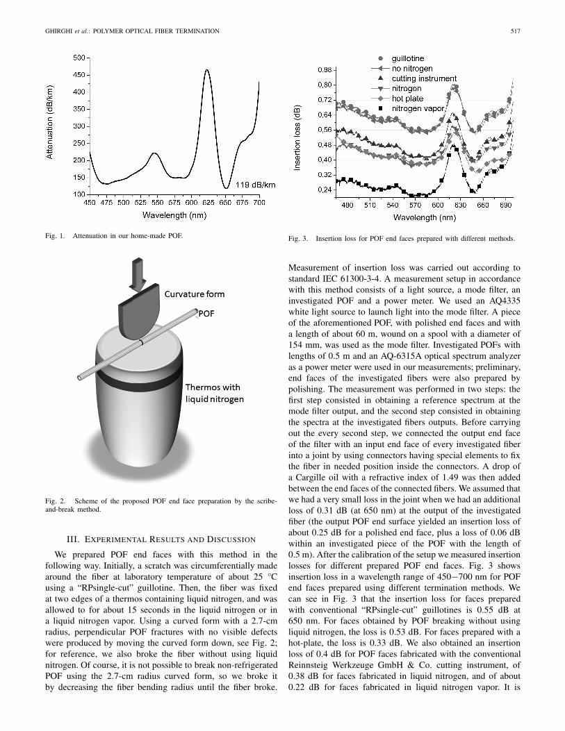
Fig. 3. Insertion loss for POF end faces prepared with different methods.
Measurement of insertion loss was carried out according tostandard IEC 61300-3-4. A measurement setup in accordancewith this method consists of a light source, a mode filter, aninvestigated POF and a power meter. We used an AQ4335white light source to launch light into the mode filter. A pieceof the aforementioned POF, with polished end faces and witha length of about 60 m, wound on a spool with a diameter of154 mm, was used as the mode filter. Investigated POFs withlengths of 0.5 m and an AQ-6315A optical spectrum analyzeras a power meter were used in our measurements; preliminary,end faces of the investigated fibers were also prepared bypolishing. The measurement was performed in two steps: thefirst step consisted in obtaining a reference spectrum at themode filter output, and the second step consisted in obtainingthe spectra at the investigated fibers outputs. Before carryingout the every second step, we connected the output end faceof the filter with an input end face of every investigated fiberinto a joint by using connectors having special elements to fixthe fiber in needed position inside the connectors. A drop ofa Cargille oil with a refractive index of 1.49 was then addedbetween the end faces of the connected fibers. We assumed thatwe had a very small loss in the joint when we had an additionalloss of 0.31 dB (at 650 nm) at the output of the investigatedfiber (the output POF end surface yielded an insertion loss ofabout 0.25 dB for a polished end face, plus a loss of 0.06 dBwithin an investigated piece of the POF with the length of0.5 m). After the calibration of the setup we measured insertionlosses for different prepared POF end faces. Fig. 3 showsinsertion loss in a wavelength range of 450−700 nm for POFend faces prepared using different termination methods. Wecan see in Fig. 3 that the insertion loss for faces preparedwith conventional “RPsingle-cut” guillotines is 0.55 dB at650 nm. For faces obtained by POF breaking without usingliquid nitrogen, the loss is 0.53 dB. For faces prepared with ahot-plate, the loss is 0.33 dB. We also obtained an insertionloss of 0.4 dB for POF faces fabricated with the conventionalReinnsteig Werkzeuge GmbH & Co. cutting instrument, of0.38 dB for faces fabricated in liquid nitrogen, and of about0.22 dB for faces fabricated in liquid nitrogen vapor. It is
Fig. 4. POF fracture surfaces obtained (a) in liquid nitrogen (surface 1), and(b) in normal environmental conditions (surface 2).
Fig. 5. Relief of POF fracture fabricated in liquid nitrogen.
possible to conclude from these data that the proposed methodof POF face preparation yield lower insertion loss than theconventionally used methods of POF preparation. We alsolooked into the quality and perpendicularity of the fracturesurfaces obtained using liquid nitrogen and without using it.A National DC-163 digital optical microscope and an atomicforce microscope (AFM) with a resolution of 50 nm for 30 ×30 µm images were used in this research effort. Fig. 4 showsthe image of a POF fracture surface obtained in liquid nitrogen[Fig. 4(a)] and the image of the best POF fracture surfaceobtained under normal environmental conditions [Fig. 4(b)].The images were prepared by means of the aforementionedoptical microscope.
It is seen in Fig. 4 that it is difficult to evaluate thequality of these fracture surfaces visually. That is why we ana-lyzed the surfaces with the atomic force microscope (AFM).Figs. 5 and 6 show relief of the POF fracture surfaces shownin Fig. 4(a) and in (b), respectively.
These figures present the relief in the centers of the POFfracture surfaces. We also analyzed relief of the surfaces inintermediate zones, and in a zone near the edge of the fiber.Results of our measurements are presented in Table I. We cansee in Table I that the surface relief of the POF face fabricatedwith use of liquid nitrogen is 2 or 3 times smaller thanthe relief of the face fabricated under normal environmentalconditions.
Fig. 6. Relief of POF fracture fabricated in normal environmental conditions.
TABLE I
RELIEF OF THE INVESTIGATED FRACTURE SURFACES
OBTAINED WITH ATM
Of course, the relief in the zone near the edge of thePOF fibers is almost the same, due to the fact that the sameguillotine was used to make circumferential scratches. We alsodecided, upon preparing POF faces with the scribe-and-breakmethod, not to put the fibers into liquid nitrogen, but only toexpose them to a liquid nitrogen vapor. The experiment wasperformed with the POFs positioned at 5-10 mm above theliquid nitrogen level in a thermos; we kept the fibers in theliquid nitrogen vapor for periods of 10, 15, 20 and 30 seconds,and the time of exposure determines the temperature of thefibers at breaking. We then broke the POFs using the same2.7 cm radius curved form. Fig. 7 shows results of insertionloss measurements for the fabricated POF end faces. We cansee in Fig. 7 that the insertion loss is lower when the fibers areexposed to the liquid nitrogen vapor for about 10-15 seconds.It seems that in this case, the POF breaking temperatures arethe optimal ones for POFs on a base of PMMA. Fig. 8 showsimages obtained with the digital optical microscope of POFfracture surfaces that were fabricated in liquid nitrogen vaporafter an exposure time of 15 sec [Fig. 8(a)], and of POF frac-ture surfaces fabricated with a conventional hot-plate method[Fig. 8(b)]. In this case, we have found that the insertion lossfor POF faces fabricated in liquid nitrogen vapor is smallerthan for POF faces fabricated with the hot-plate method andis comparable to the loss of polished faces. Also, usingthe POF scribe-and-break method proposed here, we foundthe insertion loss to be mainly less than of 0.2 dB, in the20 breaks we prepared. So, using this POF end face prepara-tion method we obtained a high repetition of insertion loss.
GHIRGHI et al.: POLYMER OPTICAL FIBER TERMINATION 519
Fig. 7. Insertion loss for POF faces fabricated at different times of exposureto liquid nitrogen vapor.
Fig. 8. POF fracture surfaces fabricated (a) in liquid nitrogen vapor afterbeing exposed to the vapor for 15 seconds, (b) with a hot-plate method.
IV. CONCLUSION
In conclusion, we have demonstrated a new method ofPOF end face preparation. It includes preparing a scratchcircumferentially made around the fiber at temperature ofabout 25 °C, cooling the fiber for a short time in liquid nitrogenor liquid nitrogen vapor, and breaking the fiber using a specialcurved form. Perpendicular fractures for a home-made stepindex POF, which consists of a PMMA core with a diameterof 0.96 mm, and a single cladding from fluoro-acrylate withan outside diameter of 1.0 mm, were prepared with the radiuscurved form. The insertion loss for the fabricated POF end
faces was measured, and for comparison, we also measuredthe insertion loss for the POF end faces fabricated usingconventional methods for POF end face preparation. We havefound that by using the proposed method of POF end facepreparation, it is possible to fabricate the POF end faces withan insertion loss of about 0.2 dB, which is less than theloss when using the now existing methods for POF end facepreparation. We have also obtained a high reproducibility ininsertion loss for POF end faces fabricated using the newlyproposed method. We also believe that the proposed methodwill find a wide application for preparing end faces of POFswith a thinner core than what we used, and also for preparingend faces of microstructured POFs.
REFERENCES
[1] O. Ziemann, J. Krauser, P. E. Zamzov, and W. Daum, “Passive com-ponents for optical fibers,” in POF-Handbook, Optical Short RangeTransmission Systems, 2nd ed. Berlin Heidelberg, Germany: Springer-Verlag, 2008.
[2] M. G. Kuzyk, “Fabricating fibers,” in Polymer Fiber Optics: Materials,Physics, and Applications. Boca Raton, FL, USA: Taylor & Francis,2006.
[3] M. Rothmaier, B. Selm, S. Spichtig, D. Haensse, and M. Wolf, “Photonictextiles for pulse oximetry,” Opt. Express, vol. 16, no. 17,pp. 12973–12986, Aug. 2008.
[4] X. Lin, L. Ren, and J. Liang, “Nondestructive scheme for measuringthe attenuation coefficient of polymer optical fiber,” Opt. Lett., vol. 38,no. 4, pp. 528–530, Feb. 2013.
[5] A. Ghatak and K. Thyagarajan, Introduction to Fiber Optics. Cambridge,U.K.: Cambridge Univ. Press, 1998.
[6] S. H. Law, et al., “Cleaving of microstructured polymer optical fibres,”Opt. Commun., vol. 258, no. 2, pp. 193–202, Feb. 2006.
[7] S. H. Law, M. A. van Eijkenlenborg, G. W. Barton, C. Yan, R. Lwin,and J. Gan, “Cleaved end-face quality of microstructured polymer opticalfibres,” Opt. Commun., vol. 265, no. 2, pp. 513–520, Sep. 2006.
[8] A. Stefani, K. Nielsen, H. K. Rasmussen, and O. Bang, “Cleaving ofTOPAS and PMMA microstructured polymer optical fibers: Core-shiftand statistical quality optimization,” Opt. Commun., vol. 285, no. 7,pp. 1825–1833, Apr. 2012.
[9] D. Gloge, P. W. Smith, D. L. Bisbee, and E. L. Chinnock, “Optical fiberend preparation for low-loss splices,” Bell Syst. Tech. J., vol. 52, no. 9,pp. 1579–1588, Nov. 1973.
[10] G. D. Khoe, G. Kuyt, and J. A. Luijendijk, “Optical fiber end prepara-tion: A new method for producing perpendicular fractures in glass fibers,coated-glass fibers, and plastic-clad fibers,” Appl. Opt., vol. 20, no. 4,pp. 707–714, Feb. 1981.
[11] Cutting Tool “RPsimple-Cut” for Polymer-Optical-Fiber [Online].Available:http://www.ratioplast.com/index.php/en/component/jshopping/product/view/159/1205
[12] Tool for Cutting and Stripping MOST System Polymeric OpticalFibres, Article 8002 0004 3 [Online]. Available: http://www.rennsteig.com/en/products/cable-a-connector-tools/fibre-optic-cable/tools-for-working-fibre-optic-cable.html