University of Kentucky University of Kentucky UKnowledge UKnowledge Chemical and Materials Engineering Faculty Publications Chemical and Materials Engineering 4-23-2021 Polymers and Solvents Used in Membrane Fabrication: A Review Polymers and Solvents Used in Membrane Fabrication: A Review Focusing on Sustainable Membrane Development Focusing on Sustainable Membrane Development Xiaobo Dong University of Kentucky, [email protected]David Lu University of Kentucky, [email protected]Tequila A. L. Harris Georgia Institute of Technology Isabel C. Escobar University of Kentucky, [email protected]Follow this and additional works at: https://uknowledge.uky.edu/cme_facpub Part of the Chemical Engineering Commons, and the Materials Science and Engineering Commons Right click to open a feedback form in a new tab to let us know how this document benefits you. Right click to open a feedback form in a new tab to let us know how this document benefits you. Repository Citation Repository Citation Dong, Xiaobo; Lu, David; Harris, Tequila A. L.; and Escobar, Isabel C., "Polymers and Solvents Used in Membrane Fabrication: A Review Focusing on Sustainable Membrane Development" (2021). Chemical and Materials Engineering Faculty Publications. 80. https://uknowledge.uky.edu/cme_facpub/80 This Review is brought to you for free and open access by the Chemical and Materials Engineering at UKnowledge. It has been accepted for inclusion in Chemical and Materials Engineering Faculty Publications by an authorized administrator of UKnowledge. For more information, please contact [email protected].
Transcript
University of Kentucky University of Kentucky
UKnowledge UKnowledge
Chemical and Materials Engineering Faculty Publications Chemical and Materials Engineering
4-23-2021
Polymers and Solvents Used in Membrane Fabrication: A Review Polymers and Solvents Used in Membrane Fabrication: A Review
Focusing on Sustainable Membrane Development Focusing on Sustainable Membrane Development
Follow this and additional works at: https://uknowledge.uky.edu/cme_facpub
Part of the Chemical Engineering Commons, and the Materials Science and Engineering Commons
Right click to open a feedback form in a new tab to let us know how this document benefits you. Right click to open a feedback form in a new tab to let us know how this document benefits you.
Repository Citation Repository Citation Dong, Xiaobo; Lu, David; Harris, Tequila A. L.; and Escobar, Isabel C., "Polymers and Solvents Used in Membrane Fabrication: A Review Focusing on Sustainable Membrane Development" (2021). Chemical and Materials Engineering Faculty Publications. 80. https://uknowledge.uky.edu/cme_facpub/80
This Review is brought to you for free and open access by the Chemical and Materials Engineering at UKnowledge. It has been accepted for inclusion in Chemical and Materials Engineering Faculty Publications by an authorized administrator of UKnowledge. For more information, please contact [email protected].
Polymers and Solvents Used in Membrane Fabrication: A Review Focusing on Polymers and Solvents Used in Membrane Fabrication: A Review Focusing on Sustainable Membrane Development Sustainable Membrane Development
Digital Object Identifier (DOI) https://doi.org/10.3390/membranes11050309
Notes/Citation Information Notes/Citation Information Published in Membranes, v. 11, issue 5, 309.
This article is an open access article distributed under the terms and conditions of the Creative Commons Attribution (CC BY) license (https://creativecommons.org/licenses/by/4.0/).
This review is available at UKnowledge: https://uknowledge.uky.edu/cme_facpub/80
1 Department of Chemical and Materials Engineering, University of Kentucky, Lexington, KY 40506, USA;[email protected] (X.D.); [email protected] (D.L.)
2 George W. Woodruff School of Mechanical Engineering, Georgia Institute of Technology,Atlanta, GA 30332, USA; [email protected]
Abstract: (1) Different methods have been applied to fabricate polymeric membranes with non-solvent induced phase separation (NIPS) being one of the mostly widely used. In NIPS, a solvent orsolvent blend is required to dissolve a polymer or polymer blend. N-methyl-2-pyrrolidone (NMP),dimethylacetamide (DMAc), dimethylformamide (DMF) and other petroleum-derived solvents arecommonly used to dissolve some petroleum-based polymers. However, these components may havenegative impacts on the environment and human health. Therefore, using greener and less toxiccomponents is of great interest for increasing membrane fabrication sustainability. The chemicalstructure of membranes is not affected by the use of different solvents, polymers, or by the differencesin fabrication scale. On the other hand, membrane pore structures and surface roughness can changedue to differences in diffusion rates associated with different solvents/co-solvents diffusing intothe non-solvent and with differences in evaporation time. (2) Therefore, in this review, solventsand polymers involved in the manufacturing process of membranes are proposed to be replaced bygreener/less toxic alternatives. The methods and feasibility of scaling up green polymeric membranemanufacturing are also examined.
Membrane technology has been utilized in liquid and gas separations for decades dueto the relative ease in fabrication and operation, high selectivity rates and the absence ofsorbent regeneration. In particular, membranes have played an increasingly importantrole in desalination, water treatment, and food and pharmaceutical industry applications.Membranes can be categorized based on the material of synthesis and they are dividedinto organic (polymeric) and inorganic membranes. Organic membranes are those madeof petroleum-based synthetic polymers, including polysulfone (PS), polyethersulfone(PES), and polyvinylidene fluoride (PVDF), while inorganic membranes include ceramics,carbon molecular sieves, zeolites, amorphous silica, among others. A majority of industrialmembranes consist of synthetic or natural polymers. Furthermore, significant amountsof organic solvents are used during membrane fabrication for polymer dissolution [1];traditional solvents are petroleum-derived and include dimethylformamide (DMF), N-methyl-2-pyrrolidone (NMP), and dimethylacetamide (DMAc). However, these componentsignificantly hinder the sustainability of membranes; in particular, traditional solvents usedin synthesis and post-synthesis steps can have a negative impact on operational safety andcosts, the environment, and human health [2–4]. Due to their hazards, solvents requirespecialized control measures. Therefore, the need for greener, low-toxicity, and moresustainable solvents and polymers has prompted considerable research into the processingof renewable feedstocks to obtain platform molecules and downstream end products. The
development and usage of green solvents would allow the global solvent market, whichhas been on the order of 20 million metric tons and billions of dollars, to align with theUnited Nations’ Sustainable Development Goals (SDGs) for 2030, as would the integrationof green polymers [5–7]. Using renewable components derived from biomass, which doesnot compete with food applications, satisfies both consumer and legislative demands withregards to sustainability.
This review examines the advances in sustainable membrane development and per-formance. In particular, these advances for polymeric membranes are discussed in terms ofphase separation methods, polymers, and solvents due to their prevalent use. In addition tomembrane fabrication, evaluating the polymer-solvent interactions, extent of sustainabilityand scale-up methods are crucial aspects that are examined.
While phase separations techniques are widely used to cast microfiltration (MF), ultra-filtration (UF) and nanofiltration (NF) membranes, the gold standard method for reverseosmosis (RO) and for thin film composite NF membranes is interfacial polymerization.The development of ultra-thin polyamide membranes through interfacial polymerizationwas a groundbreaking achievement that set the foundation for modern commercial de-salination membranes. Diffusion of amine into an organic solution with acyl chloride orother highly reactive monomers results in formation of a dense polymeric membrane. Theresulting membrane is referred to as a thin film composite membrane. As the membranelayer grows, it eventually limits diffusion of amine, thus limiting the active layer to athickness between 50–200 nm. Among the most common monomers used for nanofiltrationmembranes are piperazine and trimesoyl chloride (TMC). While TMC is also used in ROmembrane, piperazine is less bulky than m-phenyldiamine, which is used in RO mem-branes and is critical for giving NF membranes selective separations properties. As theinterfacial polymerization layer is very thin, interfacial polymerization is also done on UFmembranes, so the membrane is formed without defects and has structural reinforcementduring pressure-based filtration. A schematic for the general interfacial polymerizationprocess for thin film composite (TFC) membranes is shown in Figure 1 [8].
Membranes 2021, 11, x FOR PEER REVIEW 2 of 25
low-toxicity, and more sustainable solvents and polymers has prompted considerable re-
search into the processing of renewable feedstocks to obtain platform molecules and
downstream end products. The development and usage of green solvents would allow
the global solvent market, which has been on the order of 20 million metric tons and bil-
lions of dollars, to align with the United Nations’ Sustainable Development Goals (SDGs)
for 2030, as would the integration of green polymers [5–7]. Using renewable components
derived from biomass, which does not compete with food applications, satisfies both con-
sumer and legislative demands with regards to sustainability.
This review examines the advances in sustainable membrane development and per-
formance. In particular, these advances for polymeric membranes are discussed in terms
of phase separation methods, polymers, and solvents due to their prevalent use. In addi-
tion to membrane fabrication, evaluating the polymer-solvent interactions, extent of sus-
tainability and scale-up methods are crucial aspects that are examined.
2. Membrane Fabrication
2.1. Fabrication Methods
2.1.1. Interfacial Polymerization
While phase separations techniques are widely used to cast microfiltration (MF), ul-
trafiltration (UF) and nanofiltration (NF) membranes, the gold standard method for re-
verse osmosis (RO) and for thin film composite NF membranes is interfacial polymeriza-
tion. The development of ultra-thin polyamide membranes through interfacial polymeri-
zation was a groundbreaking achievement that set the foundation for modern commercial
desalination membranes. Diffusion of amine into an organic solution with acyl chloride
or other highly reactive monomers results in formation of a dense polymeric membrane.
The resulting membrane is referred to as a thin film composite membrane. As the mem-
brane layer grows, it eventually limits diffusion of amine, thus limiting the active layer to
a thickness between 50–200 nm. Among the most common monomers used for nanofiltra-
tion membranes are piperazine and trimesoyl chloride (TMC). While TMC is also used in
RO membrane, piperazine is less bulky than m-phenyldiamine, which is used in RO mem-
branes and is critical for giving NF membranes selective separations properties. As the
interfacial polymerization layer is very thin, interfacial polymerization is also done on UF
membranes, so the membrane is formed without defects and has structural reinforcement
during pressure-based filtration. A schematic for the general interfacial polymerization
process for thin film composite (TFC) membranes is shown in Figure 1 [8].
Figure 1. Schematic of interfacial polymerization preparation of TFC membrane. Reprinted with permission from [8],
Copyright 2011 IACSIT Publishing.
2.1.2. Phase Separation Methods
Membranes are commonly comprised of polymeric [9,10], ceramic [11,12], stainless
steel [13,14], and hybrid materials [15]. From these, polymeric membranes are the most
Figure 1. Schematic of interfacial polymerization preparation of TFC membrane. Reprinted with permission from [8],Copyright 2011 IACSIT Publishing.
2.1.2. Phase Separation Methods
Membranes are commonly comprised of polymeric [9,10], ceramic [11,12], stainlesssteel [13,14], and hybrid materials [15]. From these, polymeric membranes are the mostpopular due to the high selectivity rates, relative ease of operation and surface featuremodifications, and the vast extent of studies [16]. Therefore, this discussion focuses on poly-meric membranes and their phase separation-based fabrication methods. Namely, these
Membranes 2021, 11, 309 3 of 25
methods include non-solvent induced phase separation (NIPS), temperature induced phaseseparation (TIPS), vapor induced phase separation (VIPS) and solvent evaporation inducedphase separation (EIPS). Each phase separation method is defined and discussed in termsof several literature studies and compared with respect to advantages and disadvantages.
Non-solvent induced phase separation (NIPS) is a conventional method to fabricateporous polymeric membranes, as displayed in Figure 2. First, a polymer or polymer mixtureis dissolved by at least one solvent to form a homogeneous dope solution; pore formersand other additives that influence the membrane formation may also be included in thesolution [17,18]. The dope solution is then cast as a liquid film on a substrate, commonly aglass plate or a polymeric substrate. The liquid film on the substrate is then immersed into acoagulation non-solvent bath, such as water in most instances. Afterwards, phase inversionoccurs as the solvent in the film exchanges with the non-solvent [19]. This process resultsin the formation of an asymmetric polymeric membrane with a dense selective layer and aporous supportive sublayer. These two layers have different functionality; the selectivelayer provides the separation selectivity for the membranes due to size exclusion or charge,while the porous support layer provides mechanical strength and stability underneath theselective layer [20]. Pagliero et al. [21] used NIPS to prepare polyvinylidene fluoride (PVDF)membranes for membrane distillation and concluded that the principal factor affectingthe membrane structure was the rate of crystallization of PVDF during the liquid-liquidde-mixing process.
Membranes 2021, 11, x FOR PEER REVIEW 3 of 25
popular due to the high selectivity rates, relative ease of operation and surface feature
modifications, and the vast extent of studies [16]. Therefore, this discussion focuses on
polymeric membranes and their phase separation-based fabrication methods. Namely,
these methods include non-solvent induced phase separation (NIPS), temperature in-
oration induced phase separation (EIPS). Each phase separation method is defined and
discussed in terms of several literature studies and compared with respect to advantages
and disadvantages.
Non-solvent induced phase separation (NIPS) is a conventional method to fabricate
porous polymeric membranes, as displayed in Figure 2. First, a polymer or polymer mix-
ture is dissolved by at least one solvent to form a homogeneous dope solution; pore for-
mers and other additives that influence the membrane formation may also be included in
the solution [17,18]. The dope solution is then cast as a liquid film on a substrate, com-
monly a glass plate or a polymeric substrate. The liquid film on the substrate is then im-
mersed into a coagulation non-solvent bath, such as water in most instances. Afterwards,
phase inversion occurs as the solvent in the film exchanges with the non-solvent [19]. This
process results in the formation of an asymmetric polymeric membrane with a dense se-
lective layer and a porous supportive sublayer. These two layers have different function-
ality; the selective layer provides the separation selectivity for the membranes due to size
exclusion or charge, while the porous support layer provides mechanical strength and
stability underneath the selective layer [20]. Pagliero et al. [21] used NIPS to prepare pol-
yvinylidene fluoride (PVDF) membranes for membrane distillation and concluded that
the principal factor affecting the membrane structure was the rate of crystallization of
PVDF during the liquid-liquid de-mixing process.
Figure 2. Non-solvent induced phase separation casting process (NIPS). Reprinted from [22], Cop-
yright 2018 MDPI.
Separately, temperature-induced phase separation (TIPS) is a phase inversion pro-
cess, as shown in Figure 3, in which a dope solution of polymers and solvents is prepared
at a temperature near the melting point of the polymer, and subsequently casted into a
film and cooled down to a lower temperature. During the temperature change, phase sep-
aration occurs and a solid film forms. Whereas, membranes fabricated using NIPS are
usually from ternary systems, TIPS can be used for binary systems, thereby simplifying
the process. However, the temperature requirement can limit TIPS as a more energy-in-
tensive fabrication method [23].
Figure 2. Non-solvent induced phase separation casting process (NIPS). Reprinted from [22], Copy-right 2018 MDPI.
Separately, temperature-induced phase separation (TIPS) is a phase inversion process,as shown in Figure 3, in which a dope solution of polymers and solvents is preparedat a temperature near the melting point of the polymer, and subsequently casted into afilm and cooled down to a lower temperature. During the temperature change, phaseseparation occurs and a solid film forms. Whereas, membranes fabricated using NIPS areusually from ternary systems, TIPS can be used for binary systems, thereby simplifying theprocess. However, the temperature requirement can limit TIPS as a more energy-intensivefabrication method [23].
Membranes 2021, 11, 309 4 of 25Membranes 2021, 11, x FOR PEER REVIEW 4 of 25
Figure 3. Temperature induced phase separation process (TIPS). Reprinted with permission from
[24]. Copyright 2012 Royal Society of Chemistry.
M’barki et al. [23] used TIPS along with crosslinking to prepare porous poly(vinyl
alcohol) (PVA) membranes. In this study, water was chosen to dissolve PVA to avoid the
use of organic solvents. The resulting membranes exhibited connected cellular pores
throughout the cross-section of the membranes. However, an open pore structure (larger
than 10 μm) was obtained instead of a defect free skin layer due to the use of water as the
solvent and higher humidity.
Vapor induced phase separation (VIPS) is another method to fabricate porous mem-
branes. As shown in Figure 4, a dope solution is prepared and cast into a liquid film that
is then exposed to the atmosphere of the non-solvent vapors, in a vapor chamber. While
similar in procedure to NIPS, the phase separation occurs with water vapor being trans-
ferred into the film, while the solvent diffuses into the vapor to form a solid membrane
film.
Figure 4. Vapor induced phase separation process (VIPS). Reprinted from [25], Copyright 2018
Journal of Membrane Science and Technology.
Zhao et al. [26] studied the use of VIPS to prepare poly(vinylidene fluoride) (PVDF)
porous membranes. The membranes exhibited a cellular structure when the vapor tem-
perature was 65 °C and relative humidity of 70% for 20 min of exposure time. Unlike NIPS,
where the dope liquid film is immersed into a non-solvent bath, the dope liquid film was
exposed to the vapor phase non-solvent during VIPS, which delays the phase separation
process and leads to a cellular membrane structure [26]. It was found that mechanical
strength was enhanced, as the cellular structures was bi-continuous [26].
Figure 3. Temperature induced phase separation process (TIPS). Reprinted with permission from [24]. Copyright 2012Royal Society of Chemistry.
M’barki et al. [23] used TIPS along with crosslinking to prepare porous poly(vinylalcohol) (PVA) membranes. In this study, water was chosen to dissolve PVA to avoidthe use of organic solvents. The resulting membranes exhibited connected cellular poresthroughout the cross-section of the membranes. However, an open pore structure (largerthan 10 µm) was obtained instead of a defect free skin layer due to the use of water as thesolvent and higher humidity.
Vapor induced phase separation (VIPS) is another method to fabricate porous mem-branes. As shown in Figure 4, a dope solution is prepared and cast into a liquid film that isthen exposed to the atmosphere of the non-solvent vapors, in a vapor chamber. While simi-lar in procedure to NIPS, the phase separation occurs with water vapor being transferredinto the film, while the solvent diffuses into the vapor to form a solid membrane film.
Membranes 2021, 11, x FOR PEER REVIEW 4 of 25
Figure 3. Temperature induced phase separation process (TIPS). Reprinted with permission from
[24]. Copyright 2012 Royal Society of Chemistry.
M’barki et al. [23] used TIPS along with crosslinking to prepare porous poly(vinyl
alcohol) (PVA) membranes. In this study, water was chosen to dissolve PVA to avoid the
use of organic solvents. The resulting membranes exhibited connected cellular pores
throughout the cross-section of the membranes. However, an open pore structure (larger
than 10 μm) was obtained instead of a defect free skin layer due to the use of water as the
solvent and higher humidity.
Vapor induced phase separation (VIPS) is another method to fabricate porous mem-
branes. As shown in Figure 4, a dope solution is prepared and cast into a liquid film that
is then exposed to the atmosphere of the non-solvent vapors, in a vapor chamber. While
similar in procedure to NIPS, the phase separation occurs with water vapor being trans-
ferred into the film, while the solvent diffuses into the vapor to form a solid membrane
film.
Figure 4. Vapor induced phase separation process (VIPS). Reprinted from [25], Copyright 2018
Journal of Membrane Science and Technology.
Zhao et al. [26] studied the use of VIPS to prepare poly(vinylidene fluoride) (PVDF)
porous membranes. The membranes exhibited a cellular structure when the vapor tem-
perature was 65 °C and relative humidity of 70% for 20 min of exposure time. Unlike NIPS,
where the dope liquid film is immersed into a non-solvent bath, the dope liquid film was
exposed to the vapor phase non-solvent during VIPS, which delays the phase separation
process and leads to a cellular membrane structure [26]. It was found that mechanical
strength was enhanced, as the cellular structures was bi-continuous [26].
Figure 4. Vapor induced phase separation process (VIPS). Reprinted from [25], Copyright 2018Journal of Membrane Science and Technology.
Zhao et al. [26] studied the use of VIPS to prepare poly(vinylidene fluoride) (PVDF)porous membranes. The membranes exhibited a cellular structure when the vapor temper-ature was 65 ◦C and relative humidity of 70% for 20 min of exposure time. Unlike NIPS,where the dope liquid film is immersed into a non-solvent bath, the dope liquid film wasexposed to the vapor phase non-solvent during VIPS, which delays the phase separationprocess and leads to a cellular membrane structure [26]. It was found that mechanicalstrength was enhanced, as the cellular structures was bi-continuous [26].
In the solvent evaporation induced phase separation (EIPS) method, illustrated inFigure 5, a homogeneous solution is prepared by dissolving a polymer in the mixture of asolvent and a non-solvent, where the solvent has higher volatility than the non-solvent.
Membranes 2021, 11, 309 5 of 25
Through evaporation of the solvent, phase separation occurs and de-mixing of polymer-solvent-non-solvent system occurs, resulting in a porous film. The pore structures can becontrolled by changing the composition of polymer-solvent-non-solvent solutions [27].
Membranes 2021, 11, x FOR PEER REVIEW 5 of 25
In the solvent evaporation induced phase separation (EIPS) method, illustrated in
Figure 5, a homogeneous solution is prepared by dissolving a polymer in the mixture of
a solvent and a non-solvent, where the solvent has higher volatility than the non-solvent.
Through evaporation of the solvent, phase separation occurs and de-mixing of polymer-
solvent-non-solvent system occurs, resulting in a porous film. The pore structures can be
controlled by changing the composition of polymer-solvent-non-solvent solutions [27].
Samuel et al. [28] investigated the use of EIPS to cast polymethylmethacrylate
(PMMA) membranes in tetrahydrofuran (THF) solvent with water as the non-solvent.
During the rapid solvent evaporation, condensation of water droplets occurred and
formed the porous polymer films. Therefore, water content affected the pore morphology
on the membrane surface; the average pore size of the obtained membranes increased
along with the water content.
The advantages and disadvantages of the four main phase-separations-based meth-
ods are summarized in Table 1. It is important to address that while all these phase sepa-
rations methods convert a dope solution from liquid to solid, most of the phase separation
methods are mass transfer processes, while TIPS alone is based on heat transfer. While
other processes have significant differences, it is important to differentiate VIPS and EIPS.
First, the mechanisms are different: The non-solvent diffuses into the polymer solution
film as vapor in VIPS. In EIPS, the solution film is originally a homogenous polymer/sol-
vent/non-solvent mixture system, and the solvent evaporation promotes phase separa-
tion. Furthermore, the driving force of phase separation in VIPS is the diffusion of the
non-solvent vapor into the solution film. Whereas, both solvent and non-solvent diffusion
from the polymer-solvent-non-solvent liquid film are responsible for phase separation in
EIPS [27,29].
Table 1. Comparison of four phase separation methods [30].
NIPS [16] TIPS [31] VIPS [29,32] EIPS [27]
Principle Mass Transfer Heat Transfer Mass Transfer Mass Transfer
Components
Polymer Polymer Polymer Polymer
Solvent Solvent Solvent Solvent
Non-solvent Non-solvent (vapor) Non-solvent
Advantages
Diverse porous struc-
ture, high selectivity,
low operation tempera-
ture
Easy control, uniform
structure, good repro-
ducibility
Crystallization, gen-
tle formation process Good reproducibility
Disadvantages
Many operation param-
eters, finger-like pore
structures do not have
High energy consump-
tion, requirements for
solvents: low molecular
Many operation pa-
rameters, energy con-
sumption
Difficult to find suita-
ble solvents and non-
solvents used in EIPS
Figure 5. Solvent evaporation induced phase separation (EIPS). Reprinted from [27], Copyright 2019Royal Society of Chemistry.
Samuel et al. [28] investigated the use of EIPS to cast polymethylmethacrylate (PMMA)membranes in tetrahydrofuran (THF) solvent with water as the non-solvent. Duringthe rapid solvent evaporation, condensation of water droplets occurred and formed theporous polymer films. Therefore, water content affected the pore morphology on themembrane surface; the average pore size of the obtained membranes increased along withthe water content.
The advantages and disadvantages of the four main phase-separations-based methodsare summarized in Table 1. It is important to address that while all these phase separationsmethods convert a dope solution from liquid to solid, most of the phase separation meth-ods are mass transfer processes, while TIPS alone is based on heat transfer. While otherprocesses have significant differences, it is important to differentiate VIPS and EIPS. First,the mechanisms are different: The non-solvent diffuses into the polymer solution film asvapor in VIPS. In EIPS, the solution film is originally a homogenous polymer/solvent/non-solvent mixture system, and the solvent evaporation promotes phase separation. Further-more, the driving force of phase separation in VIPS is the diffusion of the non-solvent vaporinto the solution film. Whereas, both solvent and non-solvent diffusion from the polymer-solvent-non-solvent liquid film are responsible for phase separation in EIPS [27,29].
Table 1. Comparison of four phase separation methods [30].
NIPS [16] TIPS [31] VIPS [29,32] EIPS [27]
Principle Mass Transfer Heat Transfer Mass Transfer Mass Transfer
Crystallization, gentleformation process Good reproducibility
Disadvantages
Many operationparameters, finger-likepore structures do nothave goodmechanical strength
High energyconsumption,requirements for solvents:low molecular weight,high boiling point, lowvolatility, high miscibilitywith polymers,thermal stability
Many operationparameters, energyconsumption
Difficult to find suitablesolvents and nonsolventsused in EIPS
Membranes 2021, 11, 309 6 of 25
From Table 1 and literature studies, it is evident that NIPS can be used to producedifferent pore morphology, as desired. In fact, NIPS is considered to be the dominantmethod for fabricating polymeric membranes and has been extensively studied in theliterature [23]. Therefore, NIPS was chosen as the principal fabrication method to discussin this review, thereby minimizing the variables and focus on investigating greener/lesstoxic polymers and solvents for this method.
2.2. NIPS Materials2.2.1. Polymers
In the fabrication of polymeric membranes, organic solvents have been used in allapplications, while polymers have been investigated in different applications. Conven-tional polymers such as cellulose acetate (CA), polysulfone (PSf), polyethersulfone (PES),polyamide (PA) and polyvinylidene fluoride (PVDF) are studied in different applications,microfiltration (MF), ultrafiltration (UF), nanofiltration (NF), reverse osmosis (RO) andothers. CA is a common polymer to make MF. UF and RO membranes; PSf, PES, PVDF areusually used to make UF and MF membranes; PA has been reported to develop membranesused in all the applications mentioned above.
CA is a polymer commonly employed in membrane fabrication and has been ex-tensively researched. CA can be used to prepare microfiltration (MF) [33], ultrafiltration(UF) [34,35], nanofiltration (NF) [36], and reverse osmosis (RO) [37] membranes, and itis usually used as a material for dialysis applications [38]. Unlike other conventionalpolymers, CA is derived from cellulose, which can be obtained from natural resourcesand is considered biodegradable. Since cellulose is insoluble, it is processed with aceticanhydride and acetic acid to form CA [23]. However, CA has several disadvantages, suchas low chemical resistance, thermal resistance, and mechanical strength [16]. As such, theaddition of additives or surface modifications are often needed to improve the propertiesof CA membranes [35,39,40].
PSf is one of the most prominent polymers used in membrane fabrication. Thepopularity of PSf is not only due to its commercial availability, but also due to the easeof processing. PSf provides a portfolio of relatively high thermal resistance, chemicalresistance and mechanical strength [16].
PES is structurally similar to PSf with suitable chemical and thermal stability [41]. Fur-thermore, the ether groups within the PES structure allow for easier chemical modificationsin comparison to PSf [39–41].
Separately, PVDF exhibits high chemical resistance, thermal resistance, and mechanicalstrength, though it is also notably hydrophobic [42]. The hydrophobicity of PVDF allowsfor the possibility to be used in membrane distillation [43,44]. Moreover, in order for themembranes to be used in water treatment, surface modification is necessary for increasingthe hydrophilicity of membranes [45].
Aside from conventional, mostly petroleum-based polymers, considerable researchhas been performed on developing and evaluating sustainable polymers. For example,cellulose [46], poly(lactic acid) (PLA) [47], bamboo fiber, chitosan, and others [48–52].Green polymers have been investigated to minimize the use of petroleum-derived poly-mers and meet the performance requirements of membranes [53–55]. These polymers arederived from natural products, which significantly decrease the carbon footprint of themanufacturing process [56].
Chitosan is a polysaccharide, a polymer derived from the deacetylation of chitin [57,58].It has numerous advantages, such as being commercially available, environmentallyfriendly, and having good chemical and thermal stability, biodegradability and mechanicalstrength. However, finding a solvent that can dissolve chitosan has proven challeng-ing [59–62]. Acetic acid is commonly used to decrease the pH of a chitosan solution,which increases the solubility of chitosan in the solution [63,64]. However, acetic acid isconsidered a hazardous solvent [64,65]. Alternatively, Cui et al. [66] used an ionic liquid(IL), 1-ethyl-3-methylimidazolium acetate ([EMIM]AC), in order to dissolve chitosan and
Membranes 2021, 11, 309 7 of 25
prepare membranes. The obtained membranes had a smooth surface without curling and astrong tensile strength of up to 24 MPa, validating that ILs have the potential to be used asalternatives to acetic acid to cast chitosan membranes.
Phuong et al. [48] investigated the use of PLA and bamboo fibers as membrane supportmaterials. PLA is a polyester derived from biomass and is biodegradable. However, thelow thermal stability and mechanical strength hindered the use of PLA. Bamboo fiberwas then introduced to increase the mechanical stability of the PLA matrix, which wasthen investigated as a membrane support. In terms of an optimized recipe, the membranesupport matrix was found to provide tensile strength comparable to that of a commercialmembrane support, as well as higher water permeance.
2.2.2. Solvents
In NIPS, solvents play an essential role in shaping the morphology of membranesand even affecting the properties and performance [16]. During membrane fabrication,large amounts of traditional organic solvents are used [1]. Traditional solvents usedin membrane synthesis, including dimethylformamide (DMF), N-methyl-2-pyrrolidone(NMP), dimethylacetamide (DMAc), dimethyl sulfoxide (DMSO), and tetrahydrofuran(THF), have the potential to be hazardous. Traditional petroleum-derived solvents canbe highly flammable, irritant, and even have reproductive toxicity [67–69]. Due to theirhazards, solvents require specialized control measures. In addition to the high toxicity of thesolvents used during polymeric membrane fabrication processes [1], energy consumptionto remove or recycle solvents from the water is significant [70].
While petroleum-derived solvents have been traditionally used in membrane fabri-cation, greener/low toxicity solvents are starting to attract attention due to the decreasedimpacts on human health and the environment from their use [1]. As the world movestowards a more bio-derived manufacturing base, the opportunities for new and bio-derivedlow hazardous solvents are only expected to increase worldwide. Recently, green solventshave been investigated for membrane fabrication, including methyl lactate, triethylphos-phate, ionic liquids, organic carbonates, PolarClean, γ-valerolactone, and others.
Methyl Lactate
Methyl lactate is biodegradable, versatile, and has the potential to dissolve CA pow-ders, resulting in a homogeneous dope solution [71]. Gonzalez et al. [71] produced amembrane polymer dope solution using CA and methyl lactate by phase inversion. Pre-pared using a green process, the resulting membranes were defect-free ultrafiltrationmembranes. Alqaheem et al. [72] investigated methyl lactate to fabricate polyetherimide(PEI) membranes on the basis that the Hansen solubility parameter indicated methyl lactatehad the potential to dissolve PEI, though the experiments subsequently failed to supportthis notion. The membranes prepared with methyl lactate have exhibited several defectsand quality issues, such as inhomogeneity, micro-voids appearing on the surface and vary-ing water permeability [71]. In addition, methyl lactate cannot dissolve a board spectrumof polymers.
Triethylphosphate
Triethylphosphate (TEP) has been used as an industrial catalyst in the agriculturalindustry. Due to its low toxicity, chemical resistance and thermal stability [42], TEP can beconsidered as a substitute for traditional solvents. Wang et al. [73] prepared polyvinylidenedifluoride (PVDF) flat-sheet membranes and a hollow-fiber membrane using TEP as asolvent. Their studies suggested that when TEP was used as a solvent for copolymer blends,a delay in phase separation was observed, and as a result, sponge-like void membraneswere formed. Sponge-like membranes resulted in low flux compared to the flux rangeof finger-like membranes. Tao et al. [74] fabricated PVDF membranes using dimethylfor-mamide (DMF), trimethylphosphate (TMP), hexamethylphosphoramide (HMPA), and TEPby phase inversion and evaluated the resulting membrane performance. It was observed
Membranes 2021, 11, 309 8 of 25
that the membranes prepared using TEP exhibited the lowest flux decline, the highest purewater, and lowest rejection of proteins as compared to other membranes; these trends weremainly attributed to the larger pore size and less compaction of the PVDF/TEP membranesin comparison to the other membranes. The study showed that TEP can be used to preparePVDF microfiltration membranes. However, the weak mechanical strength of the resultingmembranes became a limiting factor to use TEP. Chang et al. [75] also employed TEP tofabricate PVDF hollow fiber membranes for membrane distillation. Without additives, themembranes exhibited a flux of 20 kg/m2h at 60 °C with an NaCl rejection of 99.99%. How-ever, the mechanical strength of the membrane was compromised; TEP was subsequentlyintroduced in the coagulation bath, which increased the amount of TEP used. Karkhanechiet al. [76] investigated TEP to prepare polyvinylidene difluoride co-chlorotrifluoroethylene(PVDF-co-CTFE) hollow-fiber membranes and compared them to NMP. Based on the anal-ysis of the trinary phase diagram and rheological properties, it was determined that phaseseparation occurring within the TEP system was easier than within the NMP system, andthat the viscosity of the TEP system increased dramatically when water was added intothe system. However, it was pointed out that TEP waste may lead to eutrophication inbodies of water, which might stimulate algae growth, resulting in toxic algal blooms anddevastation of the habitat of aquatic animals and plants [1,76–78].
Ionic Liquids
Ionic liquids (ILs) are types of organic salts that consist of an organic cation and apolyatomic inorganic anion. The cation can be imidazolium or pyridinium, while theanion can be a halogen, triflate, or trifluoroborate. Ionic liquids are widely used to replaceenvironmentally toxic organic solvents [71,79–81]. Their vapor pressure is often negligi-ble [82]. It should be noted that some ILs (for example, [EMIM][BF4] and [BMIM][PF6])have been synthesized with a measurable vapor pressure [83,84]. Moreover, the physicaland chemical properties of ILs can be altered by changing the cations and anions to meetrequirements for different applications. ILs are non-flammable and generally have highthermal stability [60]. Chichowska-Kopczynska et al. [85] used imidazolium ILs with alkylfluoride anions in CO2 separation and reported that the supported IL membranes were sta-ble and the increase of alkyl chain length would decrease the permeation values of CO2. Ifa trifluoromethanesulfonate anion was used in CO2 separation, the solubility of CO2 couldbe lower. Furthermore, supported IL membranes can be used in hollow fiber membranefabrication. Xing et al. [86] used 1-butyl-3-methylimidazolium thiocyanate ([BMIM][SCN])to prepare flat-sheet and hollow-fiber CA membranes and compared them to membranesprepared using traditional NMP and acetone solvents. The membranes prepared with ILsexhibited a denser structure; it was also reported that ILs could be recycled and reusedto fabricate membranes. Xing et al. [87] used 1-ethyl-3-methylimidazolium thiocyanate([EMIM]SCN) and 1-ethyl-3-methylimidazolium acetate ([EMIM]OAc) to fabricate CAhollow-fiber membranes. [EMIM]OAc interacted with CA more than [EMIM]SCN, whilethe CA/[EMIM]OAc dope solution presenting a more highly entangled network thanthe CA/[EMIM]SCN dope solution. Therefore, the CA/[EMIM]OAc system was morepractical for fabricating CA membranes. Colburn et al. [88] also investigated [EMIM]OActo fabricate cellulose/graphene quantum dot (GQD) membranes. Since cellulose is difficultto dissolve in common solvents, dissolution of cellulose in an IL was evaluated in this study.Within the IL, GQDs were incorporated homogeneously into the cellulose membranes,which improved the membranes performance in regard to photoactivity and sensing. How-ever, the viscosity of dope solutions significantly increased, which has the potential to leadto deficits on the surface of the membranes during the phase inversion process.
It is important to note that the synthesis of ILs is neither clean nor energy-efficient;hence, the cost of using ILs could be high [79]. The toxicities of ILs may vary significantlyacross organisms and tropic levels [79,89–92]. Furthermore, the biodegradability of ILs isslow [89]. Considering these perspectives, ILs may be considered adequate, though theymay not be considered as ideal “green” substitutes for conventional solvents.
Membranes 2021, 11, 309 9 of 25
Organic Carbonates
Organic carbonates are classified as esters of carbonic acid and are commonly used assolvents, including propylene carbonate, glycerol 1,2-carbonate, and butylene carbonate.These solvents generally have green properties, namely low toxicity, biodegradability, andbeing synthesized in supercritical CO2 [93]. Despite usage in other applications, studies onorganic carbonates as green solvents for membrane fabrication are currently limited. Re-cently, Rasool et al. [93] used NIPS to prepare NF membranes from 15% cellulose triacetate(CTA) in dimethyl carbonate (DMC)/NMP and 15% PES in PC/NMP solvent mixtureswith rejections exceeding 90% and permeances of 17.2 LMH/bar and 10.8 LMH/bar, re-spectively; mixing the green solvents with NMP in a 2:1 ratio aided in the dissolution ofthe polymers and decreased the total volume of hazardous solvent used [93].
Rhodiasolv® PolarClean
PolarClean is a water-soluble, eco-friendly, and biodegradable polar solvent, as shownin Figure 6, with no reported health hazards when used for casting PVDF membranes [94,95].It is a green solvent commercialized by Solvay Novecare and is derived from the valoriza-tion of 2-methylglutaronitrile (MGN), which is a byproduct from the synthesis of Nylon6,6 [96,97]. As such, the production of PolarClean can reduce the carbon footprint andminimize the environmental impact [96]. Hassankiadeh et al. [94] used PolarClean tofabricate PVDF hollow-fiber membranes via TIPS. However, the rate of PolarClean outflowfrom the PVDF/PolarClean system was observed to be higher than the rate of water inflow;this difference resulted in dense hollow-fiber membranes with low-water permeability. Dueto the high miscibility of PolarClean with water, phase separation can be affected by bothtemperature changes and the diffusion of water and solvent during membrane fabrication,thus, indicating the presence of a NIPS effect during the TIPS process. Jung et al. [95]investigated the combined TIPS-NIPS (N-TIPS) effect on the membrane surface during thefabrication process, along with the kinetics of the membrane formation process. By increas-ing the coagulation bath temperature and polymer concentration, the phase separation andmembrane morphology were primarily influenced by TIPS. In addition, over-dense toplayers were also reported and required a pore-former, such as Pluronic F-127, to improvewater permeability at the expense of mechanical properties [95].
Membranes 2021, 11, x FOR PEER REVIEW 10 of 25
Figure 6. Chemical structure of Rhodiasolv® PolarClean (Methyl-5-(Dimethylamino)-2-Methyl-5-
Oxopentanoate).
Gamma-Valerolactone
Gamma-valerolactone (GVL) is a 5-carbon cyclic ester with 5 atoms in the ring. It is
water-soluble and can be bio-derived from lignocellulosic biomass, specifically from hem-
icellulose and cellulose, according to the process shown in Figure 7 [98]. Briefly, hemicel-
lulose is converted to furfural and furfural alcohol as intermediates by acid hydrolysis;
the furfural alcohol is then esterified with ethanol to produce ethyl levulinate [98–100].
Cellulose is converted to hydroxymethylfurfural (HMF) as an intermediate and then con-
verted to levulinic acid also through acid hydrolysis [99,100]. Both ethyl levulinate and
levulinic acid are hydrogenated to GVL [98]. Rasool et al. [101] prepared membranes us-
ing GVL using a variety of different polymers, most notably CA and cellulose triacetate
(CTA). Specifically, 15% CA/GVL and 10% CTA/GVL dopes were used to cast nanofiltra-
tion (NF) membranes that rejected 90% Rhodamine B at permeances of 1.8 Lm−2 h−1 bar−1
(LMH/bar), and 11.7 LMH/bar, respectively.
Figure 7. Lignocellulosic biomass and reaction pathways to produce GVL. Reprinted with permis-
sion from [98]. Copyright 2013 Royal Society of Chemistry.
PolarClean and GVL as Co-Solvents
Figure 6. Chemical structure of Rhodiasolv® PolarClean (Methyl-5-(Dimethylamino)-2-Methyl-5-Oxopentanoate).
Gamma-Valerolactone
Gamma-valerolactone (GVL) is a 5-carbon cyclic ester with 5 atoms in the ring. Itis water-soluble and can be bio-derived from lignocellulosic biomass, specifically fromhemicellulose and cellulose, according to the process shown in Figure 7 [98]. Briefly, hemi-cellulose is converted to furfural and furfural alcohol as intermediates by acid hydrolysis;the furfural alcohol is then esterified with ethanol to produce ethyl levulinate [98–100].Cellulose is converted to hydroxymethylfurfural (HMF) as an intermediate and then con-verted to levulinic acid also through acid hydrolysis [99,100]. Both ethyl levulinate andlevulinic acid are hydrogenated to GVL [98]. Rasool et al. [101] prepared membranes usingGVL using a variety of different polymers, most notably CA and cellulose triacetate (CTA).Specifically, 15% CA/GVL and 10% CTA/GVL dopes were used to cast nanofiltration
Membranes 2021, 11, 309 10 of 25
(NF) membranes that rejected 90% Rhodamine B at permeances of 1.8 Lm−2 h−1 bar−1
(LMH/bar), and 11.7 LMH/bar, respectively.
Membranes 2021, 11, x FOR PEER REVIEW 10 of 25
Figure 6. Chemical structure of Rhodiasolv® PolarClean (Methyl-5-(Dimethylamino)-2-Methyl-5-
Oxopentanoate).
Gamma-Valerolactone
Gamma-valerolactone (GVL) is a 5-carbon cyclic ester with 5 atoms in the ring. It is
water-soluble and can be bio-derived from lignocellulosic biomass, specifically from hem-
icellulose and cellulose, according to the process shown in Figure 7 [98]. Briefly, hemicel-
lulose is converted to furfural and furfural alcohol as intermediates by acid hydrolysis;
the furfural alcohol is then esterified with ethanol to produce ethyl levulinate [98–100].
Cellulose is converted to hydroxymethylfurfural (HMF) as an intermediate and then con-
verted to levulinic acid also through acid hydrolysis [99,100]. Both ethyl levulinate and
levulinic acid are hydrogenated to GVL [98]. Rasool et al. [101] prepared membranes us-
ing GVL using a variety of different polymers, most notably CA and cellulose triacetate
(CTA). Specifically, 15% CA/GVL and 10% CTA/GVL dopes were used to cast nanofiltra-
tion (NF) membranes that rejected 90% Rhodamine B at permeances of 1.8 Lm−2 h−1 bar−1
(LMH/bar), and 11.7 LMH/bar, respectively.
Figure 7. Lignocellulosic biomass and reaction pathways to produce GVL. Reprinted with permis-
sion from [98]. Copyright 2013 Royal Society of Chemistry.
PolarClean and GVL as Co-Solvents
Figure 7. Lignocellulosic biomass and reaction pathways to produce GVL. Reprinted with permissionfrom [98]. Copyright 2013 Royal Society of Chemistry.
PolarClean and GVL as Co-Solvents
Dong et al. used PolarClean and GVL to dissolve PSf to fabricate ultrafiltrationmembranes both as sole solvents and as co-solvents. When PolarClean was used as a solesolvent, it produced membranes with sponge-like pore structures that were different fromthe finger-like structures, observed when DMAc was used to cast PSf membranes [22].Furthermore, the PSf/PolarClean pore structure collapsed upon backwashing, which madethe water flux after backwashing decrease; these were considered not optimal. Conversely,GVL alone was found not to be suitable to fabricate PSf membranes because the dopeformed gel-like films instead of solid films during non-solvent-induced phase separation(NIPS) with water as the non-solvent [102], so a viable membrane was not produced. Onthe other hand, under equal amounts of PolarClean and GVL as a co-solvent mixture,it was observed that membranes had similar structural, morphological and operationalproperties compared to membranes made using the petroleum-derived and toxic solvent,DMAc [103], as shown in Figure 8.
Given the green solvents in this review, it is evident that numerous alternatives existfor potentially replacing traditional solvents. Furthermore, the derivation of green solventsfrom various sources and their potential usage as single or co-solvent mixtures supporttheir versatility for membrane applications. As more green solvents are developed andevaluated, the prospect of replacing traditional solvents and overcoming their limitationsis becoming more feasible, thereby reducing the hazards and environmental impacts ofmembrane fabrication. On the other hand, there are drawbacks and concerns towards theuse of green solvents. For example, the prices of many green solvents are higher than thoseof petroleum-derived solvents. The cost of distillation of these different green solventsshould be investigated and compared to determine the economic feasibility of solventrecovery. Last, these solvents are biodegradable so that they may cause eutrophication ofreceiving waters.
Membranes 2021, 11, 309 11 of 25
Membranes 2021, 11, x FOR PEER REVIEW 11 of 25
Dong et al. used PolarClean and GVL to dissolve PSf to fabricate ultrafiltration mem-
branes both as sole solvents and as co-solvents. When PolarClean was used as a sole sol-
vent, it produced membranes with sponge-like pore structures that were different from
the finger-like structures, observed when DMAc was used to cast PSf membranes [22].
Furthermore, the PSf/PolarClean pore structure collapsed upon backwashing, which
made the water flux after backwashing decrease; these were considered not optimal. Con-
versely, GVL alone was found not to be suitable to fabricate PSf membranes because the
dope formed gel-like films instead of solid films during non-solvent-induced phase sepa-
ration (NIPS) with water as the non-solvent [102], so a viable membrane was not pro-
duced. On the other hand, under equal amounts of PolarClean and GVL as a co-solvent
mixture, it was observed that membranes had similar structural, morphological and op-
erational properties compared to membranes made using the petroleum-derived and
toxic solvent, DMAc [103], as shown in Figure 8.
Figure 8. Cross-sectional morphologies, atomic force microscopy imaging to show roughness, and comparison of flux
decline for membranes made from dopes that used the PolarClean and GVL as co-solvents to those made using the petro-
leum-derived solvent.
Given the green solvents in this review, it is evident that numerous alternatives exist
for potentially replacing traditional solvents. Furthermore, the derivation of green sol-
vents from various sources and their potential usage as single or co-solvent mixtures sup-
port their versatility for membrane applications. As more green solvents are developed
and evaluated, the prospect of replacing traditional solvents and overcoming their limita-
tions is becoming more feasible, thereby reducing the hazards and environmental impacts
of membrane fabrication. On the other hand, there are drawbacks and concerns towards
the use of green solvents. For example, the prices of many green solvents are higher than
those of petroleum-derived solvents. The cost of distillation of these different green sol-
vents should be investigated and compared to determine the economic feasibility of sol-
vent recovery. Last, these solvents are biodegradable so that they may cause eutrophica-
tion of receiving waters.
2.3. Influencing Factors on Membrane Morphology
The morphology of polymeric membranes is dependent on numerous factors, includ-
ing the polymer(s) and solvent(s) used in the dope solution. Regardless of the component
selection, several factors related to NIPS can influence the morphology, namely evapora-
tion time, casting thickness, demixing path and diffusion rate of solvent/non-solvent.
One of the advantages to using phase separation methods is the number of adjustable
fabrication parameters that can factor into the membrane morphology and performance.
Aside from the dope solution composition, one external parameter that is often adjusted
during phase separation is the amount of time the casted solution film is exposed to air
Figure 8. Cross-sectional morphologies, atomic force microscopy imaging to show roughness, and comparison of fluxdecline for membranes made from dopes that used the PolarClean and GVL as co-solvents to those made using thepetroleum-derived solvent.
2.3. Influencing Factors on Membrane Morphology
The morphology of polymeric membranes is dependent on numerous factors, includ-ing the polymer(s) and solvent(s) used in the dope solution. Regardless of the componentselection, several factors related to NIPS can influence the morphology, namely evaporationtime, casting thickness, demixing path and diffusion rate of solvent/non-solvent.
One of the advantages to using phase separation methods is the number of adjustablefabrication parameters that can factor into the membrane morphology and performance.Aside from the dope solution composition, one external parameter that is often adjustedduring phase separation is the amount of time the casted solution film is exposed to airbefore non-solvent immersion, known as evaporation time or an evaporation step. Theaddition of evaporation time is particularly useful for systems with a volatile solvent/co-solvent as the volatile solvent/co-solvent is selectively reduced, the polymer concentrationin the top “skin” layer increases and acts as a resistance barrier between the non-solventbath and bulk membrane layers during non-solvent immersion. This increased resis-tance limits the diffusion of non-solvent into the membrane and delays the de-mixingprocess [104].
The influence of evaporation time on polymeric membrane morphology has beenexamined in several studies. Holda et al. [105] investigated the relationship between evap-oration time and membrane morphology in PSf solvent resistant nanofiltration (SRNF)membranes. SEM images of membrane cross-sections indicated that the amount of mi-crovoids found underneath the top skin layer decreased as evaporation time increased andcompletely disappeared once evaporation time surpassed 120 s. Moreover, the formationof the resistance barrier at the top surface resulted in a denser skin layer with increasingevaporation time [105]. Hendrix et al. [106] reported similar observations in the fabricationof poly(ether ether ketone) (PEEK) membranes, in which membranes fabricated at longerevaporation times exhibited fewer microvoids due to the increased polymer concentrationdecreasing water diffusion during NIPS. As such, evaporation time may serve as a tool fordensifying membranes [106].
During the immersion of the polymer film in the non-solvent coagulation bath, sol-vent diffuses out of the film while the polymer film solidifies. As a result, the volume andthickness of the film decrease, even leading to the formation of membranes with half thethickness of the initially casted polymer film in cases [106]. Manipulation of the castingthickness has influenced this process and produced different membrane morphologies.PEEK membranes with a casting thickness above 400 µm exhibited macrovoids, whereasdenser, sponge-like structures were found in thinner-cast membranes. It was speculatedthat more interaction between the polymer and solvent occurred in thicker membranes,
Membranes 2021, 11, 309 12 of 25
resulting in incomplete solvent diffusion and subsequently reduced shrinkage [106]. Sim-ilarly, a critical structure-transition thickness of 12 µm was found P84 (BTDA-TDI/MDIco-polyimide)/NMP membranes where the morphology transitioned from a sponge-likestructure to finger-like structure with increasing thickness [107].
The scale of the membrane casting, that is, doctor blade extrusion at the small batchscale and slot die casting on a roll to roll (R2R) at the large/continuous scale, have alsobeen observed to affect the morphology of membranes [108,109]. Membrane fabricationat laboratory scale is performed with a casting knife without any set velocity using astationary substrate. The dope solution is poured on the substrate manually and is spreadover the substrate without pre-determined flow rate and velocity by hand. Conversely, slotdie casting on a R2R involves predetermined process parameters, such as flow rate of thepolymer dope and velocity, hence, the dope is subjected to shear. Therefore, the chosenfabrication method can cause differences in the membrane structure.
3. Measures of System Compatibility
In order to introduce a new solvent mixture into the NIPS fabrication process, severalfactors need to be taken into consideration, namely the Hansen solubility parameter model,viscosity of the dope solution, ternary phase diagram of the polymer/solvent/nonsolventsystem, and diffusion rate of the solvent and non-solvent [109–111]. Together, these factorscontribute to modelling the thermodynamic and kinetic aspects of the system, as well as aclearer understanding of the phase inversion process.
3.1. Hansen Solubility Parameter
The interactions between the components of a dope solution (e.g., polymer, solvent,non-solvent) can influence the polymer behavior in the solution and the progression ofphase inversion and mutual solubility parameters can be used to determine these inter-actions. In particular, the Hansen solubility parameters account for the dispersion forces,polar forces, and hydrogen bonding to calculate three partial solubility parameters [112].The affinity of the polymer and solvent, deemed Ra, can be calculated using Equation (1),as shown:
Ra =√
4(δd2 − δd1)2 +
(δp2 − δp1
)2+ (δh2 − δh1)
2 (1)
where δd represents energy density from dispersion bonds, δp is energy from the dipolarintermolecular force, and δh is energy from hydrogen bonds. A small Ra value indicatesfavorable compatibility of the polymer and solvent [103]. As another component of Hansensolubility parameter theory, the parameters of a polymer and solvent form a sphere. Therelative energy difference (RED) can describe the interaction between the polymer andsolvent and can be calculated using Equation (2):
RED =Ra
R0(2)
where R0 represents the radius of the Hansen solubility parameter sphere for the polymer.A RED value equal to or less than 1 indicates a suitable solvent for the polymer [103].
3.2. Viscosity of the Dope Solution
Akin to the Hansen solubility parameter, the viscosity of the dope solution relatesto the hydrogen bonds between the polymer and solvent. As such, the viscosity can bemeasured to monitor the mixing process of the solution and estimate the optimal mixingtime and temperature. During mixing, the viscosity increases as dissolution progresses,reaching a maximum value once the polymer is fully dissolved in the solvent, thus, reachingan equilibrium state. The viscosity change over shear rate can be measured to identifythe liquid behavior of dope solution under shear force. By enabling the estimate of theviscosity at any point of time during the casting process, the relationship with the viscosity
Membranes 2021, 11, 309 13 of 25
of shear rate provides quantified support in membrane casting and can subsequently beused to manage the flow behavior [104].
3.3. Ternary Phase Diagram
Once a polymer/solvent/non-solvent mixture is selected, a ternary phase diagram canbe generated to predict the possible de-mixing behaviors of the dope solution. Each cornerof the diagram represents a pure component; the boundary lines between corners representtwo-component mixtures, while the space inside the diagram indicates the presence of allthree components. The features found within the phase diagram, including the spinodaland binodal curves, critical point, and tie lines, contribute to characterizing the phasebehavior of the mixture [113]. The ternary phase diagram, illustrated in Figure 9, displaysthese aspects for a polymer-solvent-non-solvent mixture. The ternary phase diagramtheoretical curves are significant when a new polymer or solvent is to be investigated tofabricate membranes because these curves can quantitatively guide the specific polymericmembrane formation, including the compositions of the polymer/solvent/nonsolventsystem and the prediction of morphology of the membranes.
Membranes 2021, 11, x FOR PEER REVIEW 14 of 25
Figure 9. Ternary phase diagram of polymer-solvent-non-solvent mixture. Reprinted from [113],
Copyright 2012 Australian Journal of Basic and Applied Sciences (AJBAS).
Constructing a ternary phase diagram can be done by defining the thermodynamics
of the system. Namely, cloud point measurements obtained via titration can be organized
into a cloud point curve; for a ternary system, the cloud point curve serves as the binodal
curve. Determining the spinodal curve involves extrapolation of the isothermal compress-
ibility, heat capacity, or diffusion coefficient of the system as it transitions from a stable to
metastable state [104].
A ternary phase diagram of polymer/solvent/water, as shown in Figure 9 is also com-
monly used to characterize the de-mixing processes in the phase inversion process. In
Figure 9, the binodal curve is the liquid-liquid phase boundary, and the line that connects
the two points of equilibrium compositions is the tie line. Any composition inside the bi-
nodal curve de-mixes into two different composition points, polymer-rich and polymer
lean phases, which are in thermodynamic equilibrium. The composition points outside
the binodal curve are in the same liquid phase. For the instantaneous de-mixing process,
when the liquid film immerses into water, the liquid film de-mixes immediately into a
polymer-rich phase and a polymer-lean phase. For the delayed de-mixing process, follow-
ing immersion into water, the liquid film remains outside the binodal curve, thus, indicat-
ing that the delayed de-mixing process was a relatively slow process.
Different de-mixing processes may be due to different factors; for instance, the mis-
cibility of solvent in non-solvent and the viscosity of the polymer/solvent liquid film
[110,114–116]. Low miscibility of solvent in non-solvent leads to a delayed de-mixing pro-
cess, while high miscibility of solvent in non-solvent results in an instantaneous de-mixing
process [114,115]. Similarly, high viscosity of the dope solution may lead to a delayed de-
mixing process, and low viscosity may lead to an instantaneous de-mixing process
[110,116]. As shown in Figure 10, for an instantaneous de-mixing process, the solvent/non-
solvent exchange is fast, and finger-like structures form; for a delayed de-mixing process,
the solvent/non-solvent exchange is slow, which results in spongey-like structures.
Figure 9. Ternary phase diagram of polymer-solvent-non-solvent mixture. Reprinted from [113],Copyright 2012 Australian Journal of Basic and Applied Sciences (AJBAS).
Constructing a ternary phase diagram can be done by defining the thermodynamicsof the system. Namely, cloud point measurements obtained via titration can be organizedinto a cloud point curve; for a ternary system, the cloud point curve serves as the binodalcurve. Determining the spinodal curve involves extrapolation of the isothermal compress-ibility, heat capacity, or diffusion coefficient of the system as it transitions from a stable tometastable state [104].
A ternary phase diagram of polymer/solvent/water, as shown in Figure 9 is alsocommonly used to characterize the de-mixing processes in the phase inversion process. InFigure 9, the binodal curve is the liquid-liquid phase boundary, and the line that connectsthe two points of equilibrium compositions is the tie line. Any composition inside thebinodal curve de-mixes into two different composition points, polymer-rich and polymerlean phases, which are in thermodynamic equilibrium. The composition points outsidethe binodal curve are in the same liquid phase. For the instantaneous de-mixing process,when the liquid film immerses into water, the liquid film de-mixes immediately into
Membranes 2021, 11, 309 14 of 25
a polymer-rich phase and a polymer-lean phase. For the delayed de-mixing process,following immersion into water, the liquid film remains outside the binodal curve, thus,indicating that the delayed de-mixing process was a relatively slow process.
Different de-mixing processes may be due to different factors; for instance, themiscibility of solvent in non-solvent and the viscosity of the polymer/solvent liquidfilm [110,114–116]. Low miscibility of solvent in non-solvent leads to a delayed de-mixingprocess, while high miscibility of solvent in non-solvent results in an instantaneousde-mixing process [114,115]. Similarly, high viscosity of the dope solution may leadto a delayed de-mixing process, and low viscosity may lead to an instantaneous de-mixing process [110,116]. As shown in Figure 10, for an instantaneous de-mixing pro-cess, the solvent/non-solvent exchange is fast, and finger-like structures form; for a de-layed de-mixing process, the solvent/non-solvent exchange is slow, which results inspongey-like structures.
Membranes 2021, 11, x FOR PEER REVIEW 15 of 25
Figure 10. Cross sectional morphologies of membranes formed by instantaneous and delayed de-
mixing processes. Reprinted with permission from [16]. Copyright 2011 American Chemical Soci-
ety.
3.4. Diffusion Rate of Solvent and Non-Solvent
Aside from the thermodynamic aspects of mixture compatibility, one of the main ki-
netic aspects is the diffusion rate of solvent out of the dope solution and non-solvent into
the solution, which can be used to quantify the de-mixing process. During the phase in-
version process, the chemical potential gradient is highest between the polymer solution
and non-solvent, as well as the exchange rate of solvent and non-solvent; over time, the
diffusion rate decreases as the concentration gradient levels out [104].
3.5. Case Study
Dong et al. [111] calculated the Hansen Solubility Parameters of PolarClean, GVL and
their mixtures and theoretically determined that they are suitable to dissolve polysulfone
resin. Then, a ternary phase diagram was developed using cloud point titration method
to thermodynamically predict the de-mixing behaviors of polymer/solvent system. Vis-
cosity of the dope solutions was then measured to determine their liquid behavior during
casting and guide further formulation. Last, during phase inversion, the diffusion rate of
solvent/non-solvent was measured to predict the cross-section morphology of membranes
from a kinetic perspective. These four measures were employed to study the system com-
patibility and could be used as a protocol for further study.
4. Evaluation of Membrane Sustainability
One of the main concerns for the use of green polymers and solvents in membranes
is the sustainability of polymer and solvent production. While a membrane comprised of
green components may minimize direct environmental impacts, the use of polymer/sol-
vent manufacturing processes that produce significant environmental impacts would off-
set the benefits of the product. As such, an evaluation of the environmental and health
impacts of these components with a scope spanning from raw material extraction to end-
of-use should be considered.
Life Cycle Assessments (LCA) are a common method for quantifying impacts and
can be applied to evaluating membrane sustainability. The main objectives of an LCA are
Figure 10. Cross sectional morphologies of membranes formed by instantaneous and delayed de-mixing processes. Reprinted with permission from [16]. Copyright 2011 American Chemical Society.
3.4. Diffusion Rate of Solvent and Non-Solvent
Aside from the thermodynamic aspects of mixture compatibility, one of the mainkinetic aspects is the diffusion rate of solvent out of the dope solution and non-solventinto the solution, which can be used to quantify the de-mixing process. During the phaseinversion process, the chemical potential gradient is highest between the polymer solutionand non-solvent, as well as the exchange rate of solvent and non-solvent; over time, thediffusion rate decreases as the concentration gradient levels out [104].
3.5. Case Study
Dong et al. [111] calculated the Hansen Solubility Parameters of PolarClean, GVL andtheir mixtures and theoretically determined that they are suitable to dissolve polysulfoneresin. Then, a ternary phase diagram was developed using cloud point titration method
Membranes 2021, 11, 309 15 of 25
to thermodynamically predict the de-mixing behaviors of polymer/solvent system. Vis-cosity of the dope solutions was then measured to determine their liquid behavior duringcasting and guide further formulation. Last, during phase inversion, the diffusion rate ofsolvent/non-solvent was measured to predict the cross-section morphology of membranesfrom a kinetic perspective. These four measures were employed to study the systemcompatibility and could be used as a protocol for further study.
4. Evaluation of Membrane Sustainability
One of the main concerns for the use of green polymers and solvents in membranes isthe sustainability of polymer and solvent production. While a membrane comprised ofgreen components may minimize direct environmental impacts, the use of polymer/solventmanufacturing processes that produce significant environmental impacts would offset thebenefits of the product. As such, an evaluation of the environmental and health impactsof these components with a scope spanning from raw material extraction to end-of-useshould be considered.
Life Cycle Assessments (LCA) are a common method for quantifying impacts and canbe applied to evaluating membrane sustainability. The main objectives of an LCA are toidentify stages in the life cycle of a product that significantly contribute to environmentalimpacts and to determine how a process influences alter the environmental impacts [117].Several studies have utilized the LCA framework to evaluate membrane sustainability.Yadav et al. [117] performed an LCA to determine the changes in potential environmentalimpact for substituting traditional solvents (e.g., NMP, DMAc, DMF) with ethylene carbon-ate (EC) as a green solvent, as well as substituting PSf and PVDF with CA. Potential impactcategories, used for LCA, included global warming potential (GWP; kg CO2 eq.), ionizingradiation potential (IRP; kBq Co-60 eq.), marine ecotoxicity potential (MEP; kg 1,4-DCB),human non-carcinogenic toxicity potential (HNCTP; kg 1,4-DCB eq.), land use potential(LUP; m2a crop eq.), and fossil resource scarcity (FRSP; kg oil eq.) [117]. The magnitude ofeach impact category (scaled from 0 to 30) for producing 1 kg of poly mer and solvent aredisplayed in Figure 11.
Based on the evaluation, the substitution of PSf and PVDF with CA produced mainlyminor reductions in environmental impacts. One likely reason is that converting cellu-lose into CA to improve its solubility involves the use of chemicals and the generationof byproducts that contribute to environmental impacts. However, the integration ofgreen acetylation and bio-derived feedstocks in CA production would mitigate theseimpacts [117].
To evaluate the environmental impacts of green solvent use, a PVDF/EC system wascompared to traditional solvent systems of PVDF/NMP, PVDF/DMAc, and PVDF/DMF. Itwas determined that EC accounted for only a minor portion of the environmental impactsof the system, whereas NMP, DMAc, and DMF produced larger contributions to the system.Additionally, a lower magnitude of impact was measured for the production of 1 kg of ECin comparison to the traditional solvents (illustrated in Figure 9) [117].
However, the use of LCAs to measure membrane sustainability remains limited, as isthe scope of existing LCAs on membrane sustainability. To gain a more thorough evaluationof the integration of green components into membranes, future LCA should examine theimpacts related to membrane maintenance and disposal/recycling, including a wider rangeof green polymers and solvents, and expand to take a Life Cycle Thinking (LCT) approachthat considers the social and economic aspects [118].
Membranes 2021, 11, 309 16 of 25
Membranes 2021, 11, x FOR PEER REVIEW 16 of 25
to identify stages in the life cycle of a product that significantly contribute to environmen-
tal impacts and to determine how a process influences alter the environmental impacts
[117]. Several studies have utilized the LCA framework to evaluate membrane sustaina-
bility. Yadav et al. [117] performed an LCA to determine the changes in potential environ-
mental impact for substituting traditional solvents (e.g., NMP, DMAc, DMF) with eth-
ylene carbonate (EC) as a green solvent, as well as substituting PSf and PVDF with CA.
Potential impact categories, used for LCA, included global warming potential (GWP; kg
(MEP; kg 1,4-DCB), human non-carcinogenic toxicity potential (HNCTP; kg 1,4-DCB eq.),
land use potential (LUP; m2a crop eq.), and fossil resource scarcity (FRSP; kg oil eq.) [117].
The magnitude of each impact category (scaled from 0 to 30) for producing 1 kg of poly
mer and solvent are displayed in Figure 11.
Figure 11. Magnitude of potential environmental impacts for producing 1 kg of conventional and
green polymers; and (a) solvents (b). Reprinted from [117], Copyright 2021 Elsevier.
Based on the evaluation, the substitution of PSf and PVDF with CA produced mainly
minor reductions in environmental impacts. One likely reason is that converting cellulose
into CA to improve its solubility involves the use of chemicals and the generation of by-
products that contribute to environmental impacts. However, the integration of green
acetylation and bio-derived feedstocks in CA production would mitigate these impacts
[117].
To evaluate the environmental impacts of green solvent use, a PVDF/EC system was
compared to traditional solvent systems of PVDF/NMP, PVDF/DMAc, and PVDF/DMF.
It was determined that EC accounted for only a minor portion of the environmental im-
pacts of the system, whereas NMP, DMAc, and DMF produced larger contributions to the
Figure 11. Magnitude of potential environmental impacts for producing 1 kg of conventional andgreen polymers; and (a) solvents (b). Reprinted from [117], Copyright 2021 Elsevier.
5. Scaling Up the Fabrication Process Using Green Solvents5.1. Scale Up of the Membrane Fabrication Process
Despite extensive research on membrane development and fabrication at the small,laboratory scale [22,75,86,96,102,119], there is a dearth of studies and reports on scalingup membranes. There is substantial research activity in laboratories on casting polymericmembranes. However, many of these methods, such as doctor blade casting, spin coating,dip coating, etc., only work in a batch mode and cannot be easily transferred to large-scale roll-to-roll (R2R) methods [109]. Recently, there have been studies on the scale-upof plain membranes using profile roller coating [109] and slot die casting embedded onroll-to-roll (R2R) systems [115,120,121]. Slot die casting is the most prominent methodbecause it is capable of scaling up thin films across a broad array of areas, while retainingthe functionality of the films [122,123].
Here, the doctor blade and slot die casting methods are compared as examples of thedifferent fabrication scales. As shown in Figure 12, the doctor blade casting process beginswith a dope solution being placed on a substrate, while the doctor blade is positioned at aset height above the substrate. The blade is then moved at a constant velocity to spread thesolution onto the substrate to form a film [124].
Membranes 2021, 11, 309 17 of 25
Membranes 2021, 11, x FOR PEER REVIEW 17 of 25
system. Additionally, a lower magnitude of impact was measured for the production of 1
kg of EC in comparison to the traditional solvents (illustrated in Figure 9) [117].
However, the use of LCAs to measure membrane sustainability remains limited, as
is the scope of existing LCAs on membrane sustainability. To gain a more thorough eval-
uation of the integration of green components into membranes, future LCA should exam-
ine the impacts related to membrane maintenance and disposal/recycling, including a
wider range of green polymers and solvents, and expand to take a Life Cycle Thinking
(LCT) approach that considers the social and economic aspects [118].
5. Scaling Up the Fabrication Process Using Green Solvents
5.1. Scale Up of the Membrane Fabrication Process
Despite extensive research on membrane development and fabrication at the small,
laboratory scale [22,75,86,96,102,119], there is a dearth of studies and reports on scaling
up membranes. There is substantial research activity in laboratories on casting polymeric
membranes. However, many of these methods, such as doctor blade casting, spin coating,
dip coating, etc., only work in a batch mode and cannot be easily transferred to large-scale
roll-to-roll (R2R) methods [109]. Recently, there have been studies on the scale-up of plain
membranes using profile roller coating [109] and slot die casting embedded on roll-to-roll
(R2R) systems [115,120,121]. Slot die casting is the most prominent method because it is
capable of scaling up thin films across a broad array of areas, while retaining the function-
ality of the films [122,123].
Here, the doctor blade and slot die casting methods are compared as examples of the
different fabrication scales. As shown in Figure 12, the doctor blade casting process begins
with a dope solution being placed on a substrate, while the doctor blade is positioned at
a set height above the substrate. The blade is then moved at a constant velocity to spread
the solution onto the substrate to form a film [124].
Figure 12. The doctor blade coating process. Reprinted from [125], Copyright 2013 IOP Publishing.
In the slot die casting process, a slot die, as illustrated in Figure 13a,b, is used to de-
posit a liquid solution onto a substrate that is moving at a constant velocity to form a
liquid film on the substrate, as shown in Figure 11b. The difference between the slot die
and doctor blade coating methods is that the slot die casting process is pre-metered, and
is thus, more flexible in terms of obtaining a wide range of film thicknesses.
Figure 12. The doctor blade coating process. Reprinted from [125], Copyright 2013 IOP Publishing.
In the slot die casting process, a slot die, as illustrated in Figure 13a,b, is used todeposit a liquid solution onto a substrate that is moving at a constant velocity to form aliquid film on the substrate, as shown in Figure 11b. The difference between the slot dieand doctor blade coating methods is that the slot die casting process is pre-metered, and isthus, more flexible in terms of obtaining a wide range of film thicknesses.
Membranes 2021, 11, x FOR PEER REVIEW 18 of 25
Figure 13. The slot die coating process: (a) the slot die head structure; (b) the schematic of slot die
coating process.
5.2. Comparison of Doctor Blade Casting and Slot Die Casting of Membranes
Doctor blade casting has been a popular primary film casting method in the labora-
tory [126], though it is not always the best method to fabricate membranes on an industrial
scale because the membrane morphology is largely reliant on the viscosity of the dope
solutions and, therefore, not suitable for continuous casting [127,128]. Conversely, slot die
casting is a well-developed and commonly used method to manufacture polymer films. It
is suitable for continuous casting of liquid films and has been subsequently investigated
to scale up polymeric membranes [121,123]. In manufacturing of thin films, there is a con-
stant demand to increase processing speed while maintaining film thickness to fit appli-
cations in coating industry. However, several factors, including solution properties, fab-
rication process and processing parameters can affect the film quality [120,122,127]. Fail-
ure to balance critical factors, such as processing speed and flow rate, can lead to defects
on resulting films. Scaling up from a small production scale, such as doctor blade to a
larger one, such as slot die, is not intuitively obvious and several parameters must first be
identified to determine dope solution flow rate and substrate velocity. One such parame-
ter is the surface tension of the polymer since coating speed depends on surface tension
values, as solutions with lower surface tension can restrict the coating speeds to lower
values [127]. Another key parameter is viscosity, which plays a significant role in deter-
mining the processing conditions, specifically the flow behavior and consequently fabri-
cation defects, such as air bubble entrapment, which is reduced in lower viscosity solu-
tions [120,122,127].
5.3. Advantage of Slot Die Casting for Scale Up
In most cases, laboratory methods, such as doctor blade casting, spin coating and
solution casting, are not scalable and/or do not introduce the same stress on the membrane
as those formed using scalable approaches, e.g., slot die casting. Furthermore, different
manufacturing techniques may lead to significantly different membrane properties (e.g.,
tionality, and its ability to treat water. The integration of slot die casting into a R2R system
allows for continuous casting of polymeric membranes. An illustration of a simple R2R
system embedded with a slot die coater is shown in Figure 14, which has been used to
study scale up of microfiltration, ultrafiltration and AgNP composite membranes previ-
ously [111,128]. This system allows for pumping a dope solution at a preset flow rate be-
tween two die halves onto a moving substrate positioned below the slot die by a small
distance.
Figure 13. The slot die coating process: (a) the slot die head structure; (b) the schematic of slot die coating process.
5.2. Comparison of Doctor Blade Casting and Slot Die Casting of Membranes
Doctor blade casting has been a popular primary film casting method in the labora-tory [126], though it is not always the best method to fabricate membranes on an industrialscale because the membrane morphology is largely reliant on the viscosity of the dopesolutions and, therefore, not suitable for continuous casting [127,128]. Conversely, slot diecasting is a well-developed and commonly used method to manufacture polymer films. Itis suitable for continuous casting of liquid films and has been subsequently investigated toscale up polymeric membranes [121,123]. In manufacturing of thin films, there is a constantdemand to increase processing speed while maintaining film thickness to fit applicationsin coating industry. However, several factors, including solution properties, fabricationprocess and processing parameters can affect the film quality [120,122,127]. Failure to bal-ance critical factors, such as processing speed and flow rate, can lead to defects on resultingfilms. Scaling up from a small production scale, such as doctor blade to a larger one, suchas slot die, is not intuitively obvious and several parameters must first be identified todetermine dope solution flow rate and substrate velocity. One such parameter is the surfacetension of the polymer since coating speed depends on surface tension values, as solutionswith lower surface tension can restrict the coating speeds to lower values [127]. Anotherkey parameter is viscosity, which plays a significant role in determining the processingconditions, specifically the flow behavior and consequently fabrication defects, such as airbubble entrapment, which is reduced in lower viscosity solutions [120,122,127].
Membranes 2021, 11, 309 18 of 25
5.3. Advantage of Slot Die Casting for Scale Up
In most cases, laboratory methods, such as doctor blade casting, spin coating andsolution casting, are not scalable and/or do not introduce the same stress on the membraneas those formed using scalable approaches, e.g., slot die casting. Furthermore, differ-ent manufacturing techniques may lead to significantly different membrane properties(e.g., mechanical, chemical, etc.), microstructure, particle distribution, overall membranefunctionality, and its ability to treat water. The integration of slot die casting into a R2Rsystem allows for continuous casting of polymeric membranes. An illustration of a sim-ple R2R system embedded with a slot die coater is shown in Figure 14, which has beenused to study scale up of microfiltration, ultrafiltration and AgNP composite membranespreviously [111,128]. This system allows for pumping a dope solution at a preset flowrate between two die halves onto a moving substrate positioned below the slot die by asmall distance.
Membranes 2021, 11, x FOR PEER REVIEW 19 of 25
Figure 14. Schematic of a simple R2R experimental setup with a slot die coater. Reprinted with
permission from [121]. Copyright 2020 John Wiley & Sons.
The slot die process offers the advantage of controlled coating thickness, (h) as it is
only a function of specific process parameters: Pre-metered flow rate of solution per unit
die width (Q’) and substrate speed (uw) [127]. That is, h = Q’/uw. Other process parameters,
such as the slot gap width (W) and the coating gap height (H), can affect the quality of the
film as cast with defects being introduced into the film if the process is not properly con-
trolled. The space of process parameters in which defect-free casting can occur for a given
coating fluid is called the casting/coating window [129]. A graphical representation of this
space as a function of the volumetric flow rate and the substrate speed during the coating
process and the associated defects seen at the boundaries is shown in Figure 15.
Figure 15. Schematic of a generic casting window to illustrate the upper and lower boundaries of a
slot die casting process before the onset of defects. Reprinted with permission from [120,130]. Cop-
yright 2013 Elsevier.
5.4. Case Study of Scale Up
Dong et al. [111] used the slot die technique to explore the feasibility to scale up PSf
membranes, using PolarClean and GVL and PolarClean/GVL mixtures and compared it
with the doctor blade technique and using the traditional solvent DMAc. Viscosity was
Figure 14. Schematic of a simple R2R experimental setup with a slot die coater. Reprinted withpermission from [121]. Copyright 2020 John Wiley & Sons.
The slot die process offers the advantage of controlled coating thickness, (h) as it isonly a function of specific process parameters: Pre-metered flow rate of solution per unitdie width (Q’) and substrate speed (uw) [127]. That is, h = Q’/uw. Other process parameters,such as the slot gap width (W) and the coating gap height (H), can affect the quality ofthe film as cast with defects being introduced into the film if the process is not properlycontrolled. The space of process parameters in which defect-free casting can occur for agiven coating fluid is called the casting/coating window [129]. A graphical representationof this space as a function of the volumetric flow rate and the substrate speed during thecoating process and the associated defects seen at the boundaries is shown in Figure 15.
Membranes 2021, 11, 309 19 of 25
Membranes 2021, 11, x FOR PEER REVIEW 19 of 25
Figure 14. Schematic of a simple R2R experimental setup with a slot die coater. Reprinted with
permission from [121]. Copyright 2020 John Wiley & Sons.
The slot die process offers the advantage of controlled coating thickness, (h) as it is
only a function of specific process parameters: Pre-metered flow rate of solution per unit
die width (Q’) and substrate speed (uw) [127]. That is, h = Q’/uw. Other process parameters,
such as the slot gap width (W) and the coating gap height (H), can affect the quality of the
film as cast with defects being introduced into the film if the process is not properly con-
trolled. The space of process parameters in which defect-free casting can occur for a given
coating fluid is called the casting/coating window [129]. A graphical representation of this
space as a function of the volumetric flow rate and the substrate speed during the coating
process and the associated defects seen at the boundaries is shown in Figure 15.
Figure 15. Schematic of a generic casting window to illustrate the upper and lower boundaries of a
slot die casting process before the onset of defects. Reprinted with permission from [120,130]. Cop-
yright 2013 Elsevier.
5.4. Case Study of Scale Up
Dong et al. [111] used the slot die technique to explore the feasibility to scale up PSf
membranes, using PolarClean and GVL and PolarClean/GVL mixtures and compared it
with the doctor blade technique and using the traditional solvent DMAc. Viscosity was
Figure 15. Schematic of a generic casting window to illustrate the upper and lower boundariesof a slot die casting process before the onset of defects. Reprinted with permission from [120,130].Copyright 2013 Elsevier.
5.4. Case Study of Scale Up
Dong et al. [111] used the slot die technique to explore the feasibility to scale up PSfmembranes, using PolarClean and GVL and PolarClean/GVL mixtures and compared itwith the doctor blade technique and using the traditional solvent DMAc. Viscosity was animportant factor in this investigation, as it was used to quantify the mixing time requiredto dissolve the polymers, using the solvents, and to study the liquid behavior of dopesolutions. Adding GVL into PolarClean effectively reduced the mixing time needed todissolve PSf and decreased the viscosity of the dope solution to enhance the casting window.The membranes prepared using the solvent mixture of 50% GVL and 50% PolarClean andthe slot die technique displayed similar operational parameters, including flux decline,permeability and filtration performance, compared to the membranes prepared usingDMAc and the doctor blade technique.
In view of climate change and the increasing scarcity and rising prices of naturalresources, improving resource efficiency is becoming an increasingly significant factorin manufacturing sector. Eco-manufacturing is essential for achieving sustainable greengrowth, as well as being economically sensible. In eco-manufacturing, no wastes shouldbe produced, and any by-products should be broken down by microbial action to pro-duce non-hazardous products. Eco-friendly products are also made as little as possiblefrom harmful chemicals and toxic compounds, such as petroleum-derived polymers andsolvents, wood preservatives or creosote, volatile organic compounds, chlorine, amongothers. The products should also serve multiple purposes. An example of an eco-friendlyproduct is a cloth bag made from jute or hemp that can be used for numerous tasks, suchas bagging groceries and carrying books, and it lasts for years. Eco-manufacturing is anemerging new best practice in manufacturing and other industries. Eco-friendly machin-ery and installation of greener machinery parts would also help to reduce the overallcarbon footprint.
6. Conclusions and Perspectives
Given the hazards of traditional solvents, there is an urgent need to identify alternative,green solvents for polymeric membrane fabrications that are inherently safer and meetregulations. In addition, the use of green polymers in membranes would further reducethe environmental impacts. As such, there are numerous studies on the use of differenteco-friendly polymers and solvents in polymeric membrane fabrication. However, futurestudies should further evaluate the sustainability of green component manufacturing andintegration with membranes.
Membranes 2021, 11, 309 20 of 25
While a plethora of eco-friendly solvents have been studied to cast polymeric mem-branes, the scale-up study has not been heavily addressed. More casting techniques needto be investigated in order to introduce novel green solvents into the membrane fabricationprocess at an industrial scale. Aside from the regulatory pressure of banning currentpetroleum-derived solvents, two other factors can contribute to developing the use ofgreen solvents in industry. First, the proposed green solvents can be directly used on thecurrent casting manufacturing line, thus, no, or minimum, capital investment is required.Secondly, affordable solvents with a reliable supply chain would increase the possibilityfor green solvents being considered in industry. Considering all factors, there is no doubtthat eco-friendly solvents will be used in membrane manufacturing processes as promisingsolutions continue to emerge.
Author Contributions: Writing–original draft preparation, X.D. and D.L.; writing–review and edit-ing, T.A.L.H.; writing-review and editing, supervision, funding acquisition, I.C.E. All authors haveread and agreed to the published version of the manuscript.
Funding: This research was funded by the National Science Foundation (NSF) under CooperativeAgreement (grant number 1355438), by the NSF KY EPSCoR Program, by NSF DGE: NRT 1922694,and by NSF CMMI 1562255, which funded Ara Parsekian who contributed Figure 13a,b.
Institutional Review Board Statement: Not applicable.
Informed Consent Statement: Not applicable.
Data Availability Statement: The data presented in this study is based on a literature review ofpublished materials and are available on request from the corresponding author.
Conflicts of Interest: The authors declare no conflict of interest.
References1. Figoli, A.; Marino, T.; Simone, S.; Di Nicolò, E.; Li, X.-M.; He, T.; Tornaghi, S.; Drioli, E. Towards non-toxic solvents for membrane
preparation: A review. Green Chem. 2014, 16, 4034–4059. [CrossRef]2. Clark, J.H.; Tavener, S.J. Alternative Solvents: Shades of Green. Org. Process. Res. Dev. 2007, 11, 149–155. [CrossRef]3. Jessop, P.G. Searching for green solvents. Green Chem. 2011, 13, 1391–1398. [CrossRef]4. Capello, C.; Fischer, U.; Hungerbühler, K. What is a green solvent? A comprehensive framework for the environmental assessment
of solvents. Green Chem. 2007, 9, 927–934.5. Clark, J.H.; Farmer, T.J.; Hunt, A.J.; Sherwood, J. Opportunities for Bio-Based Solvents Created as Petrochemical and Fuel Products
Transition towards Renewable Resources. Int. J. Mol. Sci. 2015, 16, 17101–17159. [CrossRef]6. Gu, Y.; Jérôme, F. Bio-based solvents: An emerging generation of fluids for the design of eco-efficient processes in catalysis and
organic chemistry. Chem. Soc. Rev. 2013, 42, 9550–9570. [CrossRef] [PubMed]7. Nie, L.; Chuah, C.Y.; Bae, T.; Lee, J. Graphene-Based Advanced Membrane Applications in Organic Solvent Nanofiltration. Adv.
Funct. Mater. 2021, 31, 2006949. [CrossRef]8. Lau, W.J.; Ismail, A.F. Progress in interfacial polymerization technique on composite membrane preparation. In Proceedings of
the 2011 2nd International Conference on Environmental Engineering and Applications (ICEEA 2011), Shanghai, China, 19–21August 2011.
9. Wong, C.Y.; Wong, W.Y.; Loh, K.S.; Daud, W.R.W.; Lim, K.L.; Khalid, M.; Walvekar, R. Development of Poly(Vinyl Alcohol)-BasedPolymers as Proton Exchange Membranes and Challenges in Fuel Cell Application: A Review. Polym. Rev. 2020, 60, 171–202.[CrossRef]
10. Rosli, N.A.H.; Loh, K.S.; Wong, W.Y.; Yunus, R.M.; Lee, T.K.; Ahmad, A.; Chong, S.T. Review of Chitosan-Based Polymers asProton Exchange Membranes and Roles of Chitosan-Supported Ionic Liquids. Int. J. Mol. Sci. 2020, 21, 632. [CrossRef]
11. Chen, M.; Zhu, L.; Chen, J.; Yang, F.; Tang, C.Y.; Guiver, M.D.; Dong, Y. Spinel-based ceramic membranes coupling solid sludgerecycling with oily wastewater treatment. Water Res. 2020, 169, 115180. [CrossRef]
15. Filippov, A.; Petrova, D.; Falina, I.; Kononenko, N.; Ivanov, E.; Lvov, Y.; Vinokurov, V. Transport asymmetry of novel bi-layerhybrid perfluorinated membranes on the base of mf-4sc modified by halloysite nanotubes with platinum. Polymers 2018, 10, 366.[CrossRef]
16. Guillen, G.R.; Pan, Y.; Li, M.; Hoek, E.M.V. Preparation and Characterization of Membranes Formed by Nonsolvent InducedPhase Separation: A Review. Ind. Eng. Chem. Res. 2011, 50, 3798–3817. [CrossRef]
17. Hausman, R.; Digman, B.; Escobar, I.C.; Coleman, M.; Chung, T.-S.; Chung, N.T.-S. Functionalization of polybenzimidizolemembranes to impart negative charge and hydrophilicity. J. Membr. Sci. 2010, 363, 195–203. [CrossRef]
19. Kim, J.; van der Bruggen, B. The use of nanoparticles in polymeric and ceramic membrane structures: Review of manufacturingprocedures and performance improvement for water treatment. Environ. Pollut. 2010, 158, 2335–2349. [CrossRef]
20. Mallevialle, J.; Bersillon, J.L.; Anselme, C.; Aptel, P. Membrane Filtration in drinking-water treatment—A case story. In Influenceand Removal of Organics in Drinking Water; Mallevialle, J., Suffet, I.H., Chan, U.S., Eds.; CRC Press: Boca Raton, FL, USA, 1992;pp. 299–310.
21. Pagliero, M.; Bottino, A.; Comite, A.; Costa, C. Novel hydrophobic PVDF membranes prepared by nonsolvent induced phaseseparation for membrane distillation. J. Membr. Sci. 2020, 596, 117575. [CrossRef]
22. Dong, X.; Al-Jumaily, A.; Escobar, I.C. Investigation of the Use of a Bio-Derived Solvent for Non-Solvent-Induced Phase Separation(NIPS) Fabrication of Polysulfone Membranes. Membranes 2018, 8, 23. [CrossRef]
23. M’Barki, O.; Hanafia, A.; Bouyer, D.; Faur, C.; Sescousse, R.; Delabre, U.; Blot, C.; Guenoun, P.; Deratani, A.; Quemener, D.; et al.Greener method to prepare porous polymer membranes by combining thermally induced phase separation and crosslinking ofpoly(vinyl alcohol) in water. J. Membr. Sci. 2014, 458, 225–235. [CrossRef]
24. Lei, B.; Shin, K.-H.; Noh, D.-Y.; Jo, I.-H.; Koh, Y.-H.; Choi, W.-Y.; Kim, H.-E. Nanofibrous gelatin—Silica hybrid scaffolds mimickingthe native extracellular matrix (ECM) using thermally induced phase separation. J. Mater. Chem. 2012, 22, 14133–14140. [CrossRef]
25. Zahid, M.; Rashid, A.; Akram, S.; Rehan, Z.A.; Razzaq, W. A Comprehensive Review on Polymeric Nano-Composite Membranesfor Water Treatment. J. Membr. Sci. Technol. 2018, 8, 1–20. [CrossRef]
26. Zhao, Q.; Xie, R.; Luo, F.; Faraj, Y.; Liu, Z.; Ju, X.-J.; Wang, W.; Chu, L.-Y. Preparation of high strength poly(vinylidene fluoride)porous membranes with cellular structure via vapor-induced phase separation. J. Membr. Sci. 2018, 549, 151–164. [CrossRef]
27. Pervin, R.; Ghosh, P.; Basavaraj, M.G. Tailoring pore distribution in polymer films via evaporation induced phase separation.RSC Adv. 2019, 9, 15593–15605. [CrossRef]
28. Samuel, A.Z.; Umapathy, S.; Ramakrishnan, S. Functionalized and Postfunctionalizable Porous Polymeric Films throughEvaporation-Induced Phase Separation Using Mixed Solvents. ACS Appl. Mater. Interfaces 2011, 3, 3293–3299. [CrossRef]
29. Ismail, N.; Venault, A.; Mikkola, J.-P.; Bouyer, D.; Drioli, E.; Kiadeh, N.T.H. Investigating the potential of membranes formed bythe vapor induced phase separation process. J. Membr. Sci. 2020, 597, 117601. [CrossRef]
31. Kim, J.F.; Kim, J.H.; Lee, Y.M.; Drioli, E. Thermally induced phase separation and electrospinning methods for emergingmembrane applications: A review. AIChE J. 2016, 62, 461–490. [CrossRef]
32. Khare, V.P.; Greenberg, A.R.; Krantz, W.B. Vapor-induced phase separation—Effect of the humid air exposure step on membranemorphology: Part I. Insights from mathematical modeling. J. Membr. Sci. 2005, 258, 140–156. [CrossRef]
33. Chen, Z.; Deng, M.; Chen, Y.; He, G.; Wu, M.; Wang, J. Preparation and performance of cellulose acetate/polyethyleneimineblend microfiltration membranes and their applications. J. Membr. Sci. 2004, 235, 73–86. [CrossRef]
34. Sivakumar, M.; Mohan, D.R.; Rangarajan, R. Studies on cellulose acetate-polysulfone ultrafiltration membranes: II. Effect ofadditive concentration. J. Membr. Sci. 2006, 268, 208–219. [CrossRef]
35. Kutowy, O.; Sourirajan, S. Cellulose acetate ultrafiltration membranes. J. Appl. Polym. Sci. 1975, 19, 1449–1460. [CrossRef]36. Haddada, R.; Ferjani, E.; Roudesli, M.S.; Deratani, A. Properties of cellulose acetate nanofiltration membranes. Application to
brackish water desalination. Desalination 2004, 167, 403–409. [CrossRef]37. Duarte, A.P.; Cidade, M.T.; Bordado, J.C. Cellulose acetate reverse osmosis membranes: Optimization of the composition. J. Appl.
Polym. Sci. 2006, 100, 4052–4058. [CrossRef]38. Idris, A.; Yet, L.K. The effect of different molecular weight PEG additives on cellulose acetate asymmetric dialysis membrane
performance. J. Membr. Sci. 2006, 280, 920–927. [CrossRef]39. Zhao, C.; Xue, J.; Ran, F.; Sun, S. Modification of polyethersulfone membranes—A review of methods. Prog. Mater. Sci. 2013, 58,
76–150. [CrossRef]40. Otitoju, T.A.; Ahmad, A.L.; Ooi, B.S. Recent advances in hydrophilic modification and performance of polyethersulfone (PES)
membrane via additive blending. RSC Adv. 2018, 8, 22710–22728. [CrossRef]41. van der Bruggen, B. Chemical modification of polyethersulfone nanofiltration membranes: A review. J. Appl. Polym. Sci. 2009,
114, 630–642. [CrossRef]42. Liu, F.; Hashim, N.A.; Liu, Y.; Abed, M.M.; Li, K. Progress in the production and modification of PVDF membranes. J. Membr. Sci.
43. Eykens, L.; de Sitter, K.; Dotremont, C.; Pinoy, L.; van der Bruggen, B. Membrane synthesis for membrane distillation: A review.Sep. Purif. Technol. 2017, 182, 36–51. [CrossRef]
44. Alkhudhiri, A.; Darwish, N.; Hilal, N. Membrane distillation: A comprehensive review. Desalination 2012, 287, 2–18. [CrossRef]45. Kang, G.-D.; Cao, Y.-M. Application and modification of poly(vinylidene fluoride) (PVDF) membranes—A review. J. Membr. Sci.
2014, 463, 145–165. [CrossRef]46. Colburn, A.; Vogler, R.J.; Patel, A.; Bezold, M.; Craven, J.; Liu, C.; Bhattacharyya, D. Composite Membranes Derived from
Cellulose and Lignin Sulfonate for Selective Separations and Antifouling Aspects. Nanomaterials 2019, 9, 867. [CrossRef] [PubMed]47. Galiano, F.; Briceño, K.; Marino, T.; Molino, A.; Christensen, K.V.; Figoli, A. Advances in biopolymer-based membrane preparation
and applications. J. Membr. Sci. 2018, 564, 562–586. [CrossRef]48. Le Phuong, H.A.; Ayob, N.A.I.; Blanford, C.F.; Rawi, N.F.M.; Szekely, G. Nonwoven Membrane Supports from Renewable
S.N.; Koutahzadeh, N.; et al. Sustainable Novel Bamboo-Based Membranes for Water Treatment Fabricated by Regeneration ofBamboo Waste Fibers. ACS Sustain. Chem. Eng. 2020, 8, 4225–4235. [CrossRef]
50. Clasen, C.; Wilhelms, A.T.; Kulicke, W.-M. Formation and Characterization of Chitosan Membranes. Biomacromolecules 2006, 7,3210–3222. [CrossRef]
51. Ray, M.; Pal, K.; Anis, A.; Banthia, A.K. Development and Characterization of Chitosan-Based Polymeric Hydrogel Membranes.Des. Monomers Polym. 2010, 13, 193–206. [CrossRef]
52. Thakur, V.K.; Voicu, S.I. Recent advances in cellulose and chitosan based membranes for water purification: A concise review.Carbohydr. Polym. 2016, 146, 148–165. [CrossRef] [PubMed]
53. Gaur, S.S.; Dhar, P.; Sonowal, A.; Sharma, A.; Kumar, A.; Katiyar, V. Thermo-mechanically stable sustainable polymer based solidelectrolyte membranes for direct methanol fuel cell applications. J. Membr. Sci. 2017, 526, 348–354. [CrossRef]
54. Baig, M.I.; Durmaz, E.N.; Willott, J.D.; De Vos, W.M. Sustainable Membrane Production through Polyelectrolyte ComplexationInduced Aqueous Phase Separation. Adv. Funct. Mater. 2019, 30, 1907344. [CrossRef]
55. Goh, P.S.; Wong, T.W.; Lim, J.W.; Ismail, A.F.; Hilal, N. Innovative and Sustainable Membrane Technology for WastewaterTreatment and Desalination Application. In Innovation Strategies in Environmental Science; Elsevier: Amsterdam, The Netherlands,2020; pp. 291–319.
57. Lee, D.W.; Lim, H.; Na Chong, H.; Shim, W.S. Advances in Chitosan Material and its Hybrid Derivatives: A Review. OpenBiomater. J. 2009, 1, 10–20. [CrossRef]
58. Rathke, T.D.; Hudson, S.M. Review of Chitin and Chitosan as Fiber and Film Formers. J. Macromol. Sci. Part C 1994, 34, 375–437.[CrossRef]
59. King, C.; Shamshina, J.L.; Gurau, G.; Berton, P.; Khan, N.F.A.F.; Rogers, R.D. A platform for more sustainable chitin films from anionic liquid process. Green Chem. 2016, 19, 117–126. [CrossRef]
60. Silva, S.S.; Mano, J.F.; Reis, R.L. Ionic liquids in the processing and chemical modification of chitin and chitosan for biomedicalapplications. Green Chem. 2017, 19, 1208–1220. [CrossRef]
61. Galvis-Sánchez, A.C.; Sousa, A.M.M.; Hilliou, L.; Gonçalves, M.P.; Souza, H.K.S. Thermo-compression molding of chitosan with adeep eutectic mixture for biofilms development. Green Chem. 2015, 18, 1571–1580. [CrossRef]
62. Sanjari, A.J.; Asghari, M. A Review on Chitosan Utilization in Membrane Synthesis. ChemBioEng Rev. 2016, 3, 134–158. [CrossRef]63. Lieder, R.; Darai, M.; Örlygsson, G.; Sigurjonsson, O.E. Solution casting of chitosan membranes for in vitro evaluation of
bioactivity. Biol. Proced. Online 2013, 15, 11. [CrossRef]64. Ma, B.; Li, X.; Qin, A.; He, C. A comparative study on the chitosan membranes prepared from glycine hydrochloride and acetic
acid. Carbohydr. Polym. 2013, 91, 477–482. [CrossRef]65. Ratcliffe, A.; Baker, A.; Smith, D. Successful management of 70% acetic acid ingestion on the intensive care unit: A case report. J.
Intensive Care Soc. 2018, 19, 56–60. [CrossRef] [PubMed]66. Cui, L.; Gao, S.; Song, X.; Huang, L.; Dong, H.; Liu, J.; Chen, F.; Yu, S. Preparation and characterization of chitosan membranes.
Hyg. Assoc. J. 1969, 30, 470–476. [CrossRef]68. Smallwood, I. Handbook of Organic Solvent Properties; Butterworth-Heinemann: Oxford, UK, 2012.69. Gold, R.; Phillips, J.T.; Havrdova, E.; Bar-Or, A.; Kappos, L.; Kim, N.; Thullen, T.; Valencia, P.; Oliva, L.; Novas, M.; et al.
Delayed-Release Dimethyl Fumarate and Pregnancy: Preclinical Studies and Pregnancy Outcomes from Clinical Trials andPostmarketing Experience. Neurol. Ther. 2015, 4, 93–104. [CrossRef] [PubMed]
70. Razali, M.; Kim, J.F.; Attfield, M.P.; Budd, P.M.; Drioli, E.; Lee, Y.M.; Szekely, G. Sustainable wastewater treatment and recyclingin membrane manufacturing. Green Chem. 2015, 17, 5196–5205. [CrossRef]
71. Medina-Gonzalez, Y.; Aimar, P.; Lahitte, J.-F.; Remigy, J.-C. Towards green membranes: Preparation of cellulose acetate ultrafiltra-tion membranes using methyl lactate as a biosolvent. Int. J. Sustain. Eng. 2011, 4, 75–83. [CrossRef]
72. AlQaheem, Y.; Alomair, A.; Alhendi, A.; Alkandari, S.; Tanoli, N.; Alnajdi, N.; Quesada-Peréz, A. Preparation of polyetherimidemembrane from non-toxic solvents for the separation of hydrogen from methane. Chem. Central J. 2018, 12, 80. [CrossRef]
73. Wang, J.-H.; Zhang, Y.-H.; Xu, Y.-Y.; Zhu, B.-K.; Xu, H. Fabrication of hydrophilic and sponge-like PVDF/brush-like copolymerblend membranes using triethylphosphate as solvent. Chin. J. Polym. Sci. 2014, 32, 143–150. [CrossRef]
74. Tao, M.-M.; Liu, F.; Ma, B.-R.; Xue, L.-X. Effect of solvent power on PVDF membrane polymorphism during phase inversion.Desalination 2013, 316, 137–145. [CrossRef]
75. Chang, J.; Zuo, J.; Zhang, L.; O’Brien, G.S.; Chung, T.-S. Using green solvent, triethyl phosphate (TEP), to fabricate highly porousPVDF hollow fiber membranes for membrane distillation. J. Membr. Sci. 2017, 539, 295–304. [CrossRef]
76. Karkhanechi, H.; Vaselbehagh, M.; Jeon, S.; Shaikh, A.R.; Wang, D.-M.; Matsuyama, H. Preparation and characterization ofpolyvinylidenedifluoride-co-chlorotrifluoroethylene hollow fiber membranes with high alkaline resistance. Polymer 2018, 145,310–323. [CrossRef]
77. Paerl, H.W.; Whitall, D.R. Anthropogenically-derived atmospheric nitrogen deposition, marine eutrophication and harmful algalbloom expansion: Is there a link? Ambio 1999, 28, 307–311.
79. Ratti, R. Ionic Liquids: Synthesis and Applications in Catalysis. Adv. Chem. 2014, 2014, 729842. [CrossRef]80. Rogers, R.D.; Seddon, K.R. Ionic liquids—Solvents of the future? Science 2003, 302, 792–793. [CrossRef]81. Earle, M.J.; Seddon, K.R. Ionic liquids: Green solvents for the future. In Pure and Applied Chemistry; ACS Publications: Washington,
DC, USA, 2000; p. 1391.82. Heym, F.; Haber, J.; Korth, W.; Etzold, B.J.M.; Jess, A. Vapor Pressure of Water in Mixtures with Hydrophilic Ionic Liquids—A
Contribution to the Design of Processes for Drying of Gases by Absorption in Ionic Liquids. Chem. Eng. Technol. 2010, 33,1625–1634. [CrossRef]
83. Dai, C.; Sui, X.; Lei, Z. Vapor pressure measurements and predictions for the binary systems containing ionic liquid [EMIM][BF 4]and formic acid/acetic acid. J. Mol. Liq. 2018, 256, 471–479. [CrossRef]
84. Tomida, D.; Tani, Y.; Qiao, K.; Yokoyama, C. Vapor pressure and liquid density of 1-butyl-3-methylimidazolium hexafluorophos-phate and ammonia mixtures. High Temp. High Press. 2018, 47, 101–116.
85. Cichowska-Kopczynska, I.; Joskowska, M.; Debski, B.; Łuczak, J.; Aranowski, R. Influence of Ionic Liquid Structure on SupportedIonic Liquid Membranes Effectiveness in Carbon Dioxide/Methane Separation. J. Chem. 2013, 2013, 932863. [CrossRef]
86. Xing, D.Y.; Chan, S.Y.; Chung, T.-S. Molecular interactions between polybenzimidazole and [EMIM]OAc, and derived ultrafiltra-tion membranes for protein separation. Green Chem. 2012, 14, 1405–1412. [CrossRef]
87. Xing, D.Y.; Dong, W.Y.; Chung, T.-S. Effects of Different Ionic Liquids as Green Solvents on the Formation and UltrafiltrationPerformance of CA Hollow Fiber Membranes. Ind. Eng. Chem. Res. 2016, 55, 7505–7513. [CrossRef]
88. Colburn, A.; Wanninayake, N.; Kim, D.; Bhattacharyya, D. Cellulose-graphene quantum dot composite membranes using ionicliquid. J. Membr. Sci. 2018, 556, 293–302. [CrossRef] [PubMed]
89. Romero, A.; Santos, A.; Tojo, J.; Rodríguez, A. Toxicity and biodegradability of imidazolium ionic liquids. J. Hazard. Mater. 2008,151, 268–273. [CrossRef] [PubMed]
90. Docherty, K.M.; Kulpa, J.C.F. Toxicity and antimicrobial activity of imidazolium and pyridinium ionic liquids. Green Chem. 2005,7, 185–189. [CrossRef]
91. Pham, T.P.T.; Cho, C.-W.; Yun, Y.-S. Environmental fate and toxicity of ionic liquids: A review. Water Res. 2010, 44, 352–372.[CrossRef]
92. Ventura, S.P.M.; Gonçalves, A.M.M.; Sintra, T.; Pereira, J.L.; Gonçalves, F.; Coutinho, J.A.P. Designing ionic liquids: The chemicalstructure role in the toxicity. Ecotoxicology 2012, 22, 1–12. [CrossRef]
93. Rasool, M.A.; Pescarmona, P.P.; Vankelecom, I.F.J. Applicability of Organic Carbonates as Green Solvents for MembranePreparation. ACS Sustain. Chem. Eng. 2019, 7, 13774–13785. [CrossRef]
94. Hassankiadeh, N.T.; Cui, Z.; Kim, J.H.; Shin, D.W.; Lee, S.Y.; Sanguineti, A.; Arcella, V.; Lee, Y.M.; Drioli, E. Microporouspoly(vinylidene fluoride) hollow fiber membranes fabricated with PolarClean as water-soluble green diluent and additives. J.Membr. Sci. 2015, 479, 204–212. [CrossRef]
95. Jung, J.T.; Kim, J.F.; Wang, H.H.; di Nicolo, E.; Drioli, E.; Lee, Y.M. Understanding the non-solvent induced phase separation(NIPS) effect during the fabrication of microporous PVDF membranes via thermally induced phase separation (TIPS). J. Membr.Sci. 2016, 514, 250–263. [CrossRef]
96. Marino, T.; Blasi, E.; Tornaghi, S.; Di Nicolò, E.; Figoli, A. Polyethersulfone membranes prepared with Rhodiasolv®Polarclean aswater soluble green solvent. J. Membr. Sci. 2018, 549, 192–204. [CrossRef]
97. Randová, A.; Bartovská, L.; Morávek, P.; Matejka, P.; Novotná, M.; Matejková, S.; Drioli, E.; Figoli, A.; Lanc, M.; Friess, K.A fundamental study of the physicochemical properties of Rhodiasolv®Polarclean: A promising alternative to common andhazardous solvents. J. Mol. Liq. 2016, 224, 1163–1171. [CrossRef]
98. Alonso, D.M.; Wettstein, S.G.; Dumesic, J.A. Gamma-valerolactone, a sustainable platform molecule derived from lignocellulosicbiomass. Green Chem. 2013, 15, 584–595. [CrossRef]
99. Girisuta, B.; Janssen, A.L.P.B.M.; Heeres, H.J. Kinetic Study on the Acid-Catalyzed Hydrolysis of Cellulose to Levulinic Acid. Ind.Eng. Chem. Res. 2007, 46, 1696–1708. [CrossRef]
100. Girisuta, B.; Janssen, L.P.B.M.; Heeres, H.J. A kinetic study on the decomposition of 5-hydroxymethylfurfural into levulinic acid.Green Chem. 2006, 8, 701–709. [CrossRef]
101. Rasool, M.A.; Vankelecom, I.F. Use of γ-valerolactone and glycerol derivatives as bio-based renewable solvents for membranepreparation. Green Chem. 2019, 21, 1054–1064. [CrossRef]
102. Dong, X.; Shannon, H.D.; Escobar, I.C. Investigation of Polarclean and Gamma-Valerolactone as Solvents for PolysulfoneMembrane Fabrication. In Green Polymer Chemistry: New Products, Processes, and Applications; American Chemical Society:Washington, DC, USA, 2018; pp. 385–403.
103. Dong, X.; Shannon, H.D.; Parker, C.; De Jesus, S.; Escobar, I.C. Comparison of two low-hazard organic solvents as individual andcosolvents for the fabrication of polysulfone membranes. AIChE J. 2020, 66, 16790. [CrossRef]
104. Hołda, A.K.; Vankelecom, I.F. Understanding and guiding the phase inversion process for synthesis of solvent resistant nanofil-tration membranes. J. Appl. Polym. Sci. 2015, 132. [CrossRef]
105. Hołda, A.K.; Aernouts, B.; Saeys, W.; Vankelecom, I.F. Study of polymer concentration and evaporation time as phase inversionparameters for polysulfone-based SRNF membranes. J. Membr. Sci. 2013, 442, 196–205. [CrossRef]
106. Hendrix, K.; Koeckelberghs, G.; Vankelecom, I.F. Study of phase inversion parameters for PEEK-based nanofiltration membranes.J. Membr. Sci. 2014, 452, 241–252. [CrossRef]
107. Ren, J.; Zhou, J.; Deng, M. Morphology transition of asymmetric flat sheet and thickness-gradient membranes by wet phase-inversion process. Desalination 2010, 253, 1–8. [CrossRef]
108. Chede, S.; Griffiths, P.; Escobar, I.C.; Harris, T.A.L. Does casting method matter in filtration membranes? A comparison inperformance between doctor blade and slot-die extruded polymeric membranes. J. Appl. Polym. Sci. 2018, 135, 45563. [CrossRef]
109. Bucher, T.; Filiz, V.; Abetz, C.; Abetz, V. Formation of Thin, Isoporous Block Copolymer Membranes by an Upscalable ProfileRoller Coating Process—A Promising Way to Save Block Copolymer. Membranes 2018, 8, 57. [CrossRef]
110. Lakshmi, D.S.; Cundari, T.; Furia, E.; Tagarelli, A.; Fiorani, G.; Carraro, M.; Figoli, A. Preparation of Polymeric Membranes andMicrocapsules Using an Ionic Liquid as Morphology Control Additive. Macromol. Symp. 2015, 357, 159–167. [CrossRef]
111. Dong, X.; Jeong, T.J.; Kline, E.; Banks, L.; Grulke, E.; Harris, T.; Escobar, I.C. Eco-friendly solvents and their mixture for thefabrication of polysulfone ultrafiltration membranes: An investigation of doctor blade and slot die casting methods. J. Membr. Sci.2020, 614, 118510. [CrossRef]
112. Soroko, I.; Lopes, M.P.; Livingston, A. The effect of membrane formation parameters on performance of polyimide membranesfor organic solvent nanofiltration (OSN): Part A. Effect of polymer/solvent/non-solvent system choice. J. Membr. Sci. 2011, 381,152–162. [CrossRef]
113. Ayman, E.G.; Heba, A.; Sahar, A. Construction of ternary phase diagram and membrane morphology evaluation forpolyamide/formic acid/water system. Aust. J. Basic Appl. Sci. 2012, 6, 62–68.
114. Wang, H.H.; Jung, J.T.; Kim, J.F.; Kim, S.; Drioli, E.; Lee, Y.M. A novel green solvent alternative for polymeric membranepreparation via nonsolvent-induced phase separation (NIPS). J. Membr. Sci. 2019, 574, 44–54. [CrossRef]
115. Mazinani, S.; Darvishmanesh, S.; Ehsanzadeh, A.; van der Bruggen, B. Phase separation analysis of Extem/solvent/non-solventsystems and relation with membrane morphology. J. Membr. Sci. 2017, 526, 301–314. [CrossRef]
116. Kahrs, C.; Gühlstorf, T.; Schwellenbach, J. Influences of different preparation variables on polymeric membrane formation vianonsolvent induced phase separation. J. Appl. Polym. Sci. 2020, 137, 48852. [CrossRef]
117. Yadav, P.; Ismail, N.; Essalhi, M.; Tysklind, M.; Athanassiadis, D.; Tavajohi, N. Assessment of the environmental impact ofpolymeric membrane production. J. Membr. Sci. 2021, 622, 118987. [CrossRef]
118. Martins, A.A.; Caetano, N.S.; Mata, T.M. LCA for Membrane Processes. In Green Chemistry and Sustainable Technology; Springer:Singapore, 2017; pp. 23–66.
119. Xie, W.; Li, T.; Chen, C.; Wu, H.; Liang, S.; Chang, H.; Liu, B.; Drioli, E.; Wang, Q.; Crittenden, J.C. Using the Green Sol-vent Dimethyl Sulfoxide To Replace Traditional Solvents Partly and Fabricating PVC/PVC-g-PEGMA Blended UltrafiltrationMembranes with High Permeability and Rejection. Ind. Eng. Chem. Res. 2019, 58, 6413–6423. [CrossRef]
120. Bhamidipati, K.L.; Didari, S.; Harris, T.A. Slot die coating of polybenzimiazole based membranes at the air engulfment limit. J.Power Sources 2013, 239, 382–392. [CrossRef]
121. Phillips, A.; Ulsh, M.; Mackay, J.; Harris, T.; Shrivastava, N.; Chatterjee, A.; Porter, J.; Bender, G. The effect of membrane castingirregularities on initial fuel cell performance. Fuel Cells 2020, 20, 60–69. [CrossRef]
122. Ding, X.; Liu, J.; Harris, T.A.L. A review of the operating limits in slot die coating processes. AIChE J. 2016, 62, 2508–2524.[CrossRef]
123. Huang, B.-J.; Guan, C.-K.; Huang, S.-H.; Su, W.-F. Development of once-through manufacturing machine for large-area Perovskitesolar cell production. Sol. Energy 2020, 205, 192–201. [CrossRef]
124. Aegerter, M.A.; Mennig, M. (Eds.) Doctor blade. In Sol-Gel Technologies for Glass Producers and Users; Springer: Berlin/Heidelberg,Germany, 2004; pp. 89–92.
125. de Kergommeaux, A.; Fiore, A.; Faure-Vincent, J.; Pron, A.; Reiss, P. Colloidal CuInSe 2 nanocrystals thin films of low surfaceroughness. Adv. Nat. Sci. Nanosci. Nanotechnol. 2013, 4, 015004. [CrossRef]
126. Wang, C.F.; An, Y.; Li, Q.H.; Wan, S.J.; Chen, W.X.; Liu, X.D. Nonsolvent Effects on Morphology of Cellulose Acetate FilmsPrepared by Dry-Cast Process. J. Macromol. Sci. Part B 2012, 51, 2266–2275. [CrossRef]
127. Bhamidipati, K.; Didari, S.; Harris, T.A. Experimental Study on Air Entrainment in Slot Die Coating of High-Viscosity, Shear-Thinning Fluids. Chem. Eng. Sci. 2012, 80, 195–204. [CrossRef]
128. Chede, S.; Anaya, N.M.; Oyanedel-Craver, V.; Gorgannejad, S.; Harris, T.A.; Al-Mallahi, J.; Abu-Dalo, M.; Abu Qdais, H.; Escobar,I.C. Desalination using low biofouling nanocomposite membranes: From batch-scale to continuous-scale membrane fabrication.Desalination 2019, 451, 81–91. [CrossRef]
129. Ruschak, K.J. Limiting flow in a pre-metered coating device. Chem. Eng. Sci. 1976, 31, 1057–1060. [CrossRef]130. Bhamidipati, K.L. Detection and Elimination of Defects during Manufacture of high-Temperature Polymer Electrolyte Membranes.
Ph.D. Thesis, Georgia Institute of Technology, Atlanta, GA, USA, 2011.


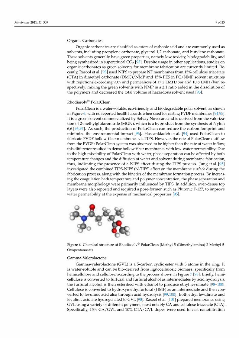
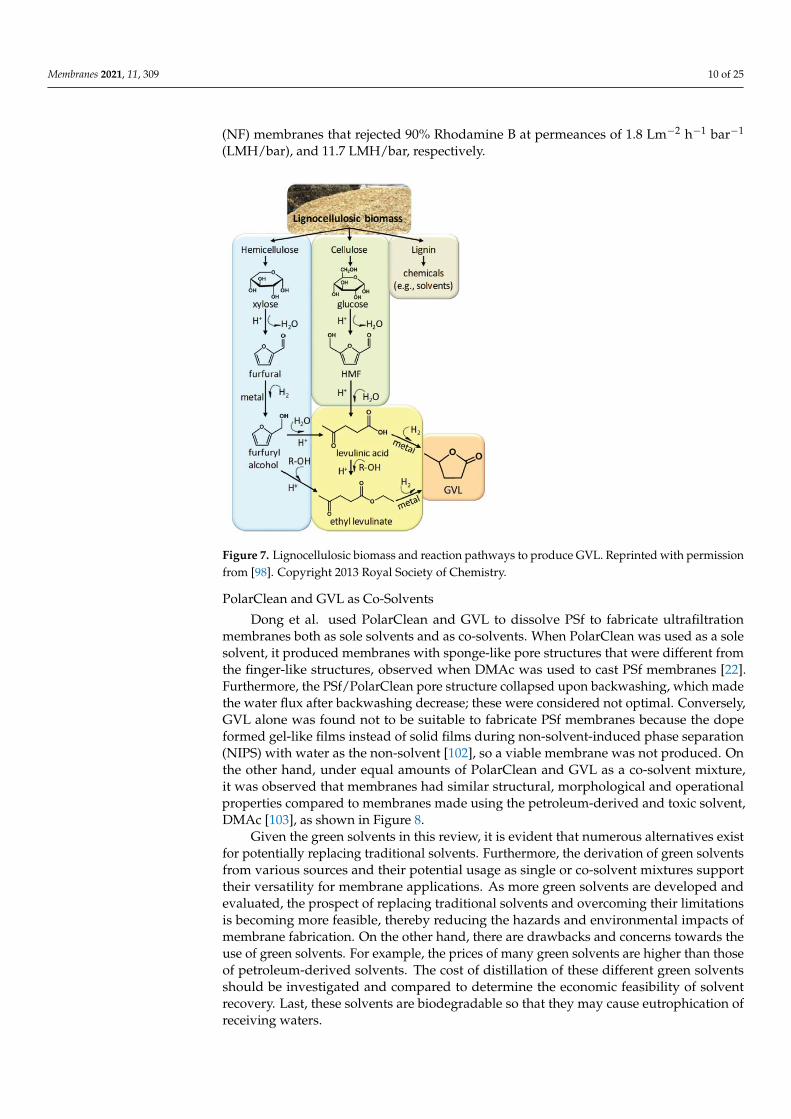


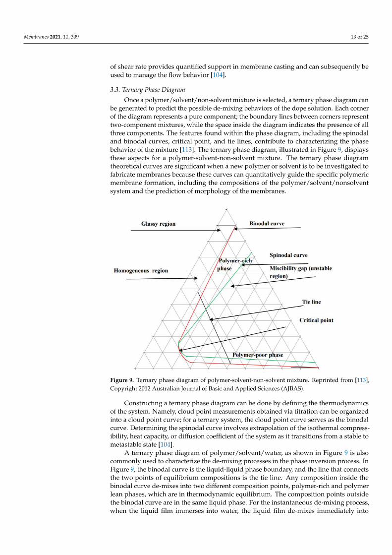


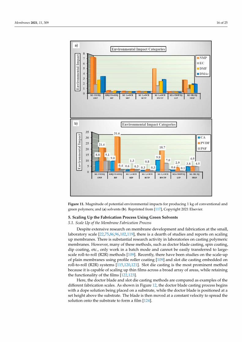


![Star polymers in good solvents from dilute to concentrated ... · star polymers [33,58–60], adsorption [20,21,23], and star polymers grafted to a wall [29,31,46]. A special place](https://static.documents.pub/doc/80x56/605faaefac599f142e1529ed/star-polymers-in-good-solvents-from-dilute-to-concentrated-star-polymers-3358a60.jpg)


