PolySwitch Resettable Devices – Telecommunications & Networking Devices RoHS Compliant, ELV Compliant 247 11 The PolySwitch families of telecommunications and networking devices help meet the growing demand for resettable overcurrent protection. These product families help provide protection against damage caused by power cross and power induction surges as defined in ITU, Telcordia GR1089 and UL60950. Available in chip, surface-mount and radial-leaded configurations, TE’s PolySwitch devices help improve the reliability of customer premise and network equipment worldwide. • Many product choices give engineers help increase design flexibility • Compatible with high-volume electronics assembly • Assist in meeting regulatory equipment requirements • Help improve line balance • Applicable for legacy POTS and modern digital communications equipment • RoHS compliant • Resettable overcurrent protection • Surface-mount, radial-leaded and chip form factors • Fast time-to-trip • Agency recognition: UL, CSA, TÜV • Resistance-sorted and matched devices available • Low parasitic capacitance/flat impedance with frequency • Modems • Phone sets • Fax machines • Phone wall outlets • Alarm systems PolySwitch Resettable Devices Telecommunications and Networking Devices Benefits Features Applications • PBX systems • MDF modules • Analog and digital line cards • T1/E1 equipment • xDSL modems and splitters • Powered ethernet systems • VoIP (Voice over Internet Protocol) equipment • LAN, WAN equipment • Customer premise equipment • Access network hardware
Transcript
Po
lyS
witc
h R
ese
ttab
le D
evic
es –
Tele
co
mm
un
icatio
ns &
Netw
ork
ing
Devic
es
RoHS Compliant, ELV Compliant 247
11
The PolySwitch families of telecommunications and
networking devices help meet the growing demand
for resettable overcurrent protection. These product
families help provide protection against damage caused
by power cross and power induction surges as defined
in ITU, Telcordia GR1089 and UL60950. Available in
chip, surface-mount and radial-leaded configurations,
TE’s PolySwitch devices help improve the reliability of
customer premise and network equipment worldwide.
• Many product choices give engineers help increase
design flexibility
• Compatible with high-volume electronics assembly
• Assist in meeting regulatory equipment requirements
• Help improve line balance
• Applicable for legacy POTS and modern digital
communications equipment
• RoHS compliant
• Resettable overcurrent protection
• Surface-mount, radial-leaded and chip form factors
• Fast time-to-trip
• Agency recognition: UL, CSA, TÜV
• Resistance-sorted and matched devices available
• Low parasitic capacitance/flat impedance
with frequency
• Modems
• Phone sets
• Fax machines
• Phone wall outlets
• Alarm systems
PolySwitch Resettable DevicesTelecommunications and Networking Devices
Benefits Features
Applications
• PBX systems
• MDF modules
• Analog and digital line cards
• T1/E1 equipment
• xDSL modems and splitters
• Powered ethernet systems
• VoIP (Voice over Internet Protocol) equipment
• LAN, WAN equipment
• Customer premise equipment
• Access network hardware
2013_CP_S11-Poly-8-TeleNetwork.indd 247 8/3/13 10:41 AM
RoHS Compliant, ELV Compliant248
11
Application Guide for PolySwitch Telecommunications and Networking Devices*
To use this guide, follow the steps below:1. Select your equipment type from the guide below.2. Select the type of protection depending on the agency and regional specifications in the second column.3. Select the form factor for your application.4. Use the Agency Specification/ PolySwitch Device Selection Guide on the next page to select a specific part number for each application
based on the agency requirements.5. Parts with fast time-to-trip or low resistance are available. Please consult a TE Circuit Protection representative.
LAN Equipment, VoIP Cards, CableTelephony NIUs, Wireless Local LoopHandsets
North America TRF250-080U TSL250-080F
GR1089 Port Type 2‡ TRF250-120 TS250-130F
GR1089 Port Type 4‡ TRF250-120T TSV250-130F
TRF250-145 TSV250-184F
TRF250-183
TRF250-184
Europe/Asia/ TRF250-120 TS250-130F
South America TRF250-120T TSV250-130F
ITU K.21 TRF250-145 TSV250-184F
TRF250-183
TSV250-184* Applies to all products which share the same prefix. † Tested with 230V gas discharge tube primary protector.
2013_CP_S11-Poly-8-TeleNetwork.indd 248 8/3/13 10:41 AM
Po
lyS
witc
h R
ese
ttab
le D
evic
es –
Tele
co
mm
un
icatio
ns &
Netw
ork
ing
Devic
es
RoHS Compliant, ELV Compliant 249
11
Protection Application Guide for PolySwitch Telecommunications and Networking Devices* Cont’d
Agency Specification/Selection Guide for Telecommunications and Networking Devices
Use the guide below to select the PolySwitch devices that are typically used in your application. The following pages contain the specifications for the part numbers recommended below. PolySwitch devices assist telecommunication equipment in meeting the applicable protection requirements of these industry specifications. Refer to individual agency specifications for test procedures and circuit schematics. Users should independently evaluate the suitability of and test each product for their application.
Family Product* Lightning Power Cross/Contact/Induction
TCF250 TCF250-100T ITU K.20 – 1.0kV 10/700µs PRC YD/T694
GR-1089 Port Types 2 and 4 – 1st Level ITU K.20/21/45 – 0.2A2s
ITU K.20/21/45 – 1A2s†
GR-1089 Port Type 4 – 120VAC, 25Asc
TCF250-120T ITU K.20/21/45 – 1.5kV 10/700µs ITU K.20/21/45 – 230VAC, 10Ω
TCF250-145T ITU K.20/21/45 – 4.0kV 10/700µs† ITU K.20/21/45 – 0.2A2s
TCF250-180 GR-1089 Port Types 2 and 4 – 1st Level ITU K.20/21/45 – 1A2s†
ITU K.20/21/45 – 10A2s†
GR-1089 Port Type 4 – 120VAC, 25Asc
* Applies to all products which share the same prefix.† Tested with 230V gas discharge tube primary protector.
ApplicationRegion/Specification
Form Factor
Radial-leaded Surface-mount Chip
Overcurrent Protection
* This list is not exhaustive. TE Circuit Protection welcomes our customers’ input for additional application ideas for PolySwitch resettable devices.† For improved line balance in these applications, resistance-matched parts are recommended.‡ May require additional impedance or coordination with primary protector.** FT600-1250 are surface-mount telecom fuse devices. FT600-0500 and FT600-2000 reference also available. See telecom fuses section.†† For details on decaSMDC050F/60-2, see surface-mount devices section.
LAN Intrabuilding Power Cross Protection
LAN Equipment, VoIP Cards, IP Phones
North America
GR1089 Port Type 4‡
TSL250-080U TSL250-080F
TRF250-120 TS250-130F
TRF250-120T TSV250-130F
TRF250-145 TSV250-184F
TRF250-183
TRF250-184
IEEE 802.3AF/AT Power over
Ethernet protection
Powered Ethernet Switches and Terminals,
IP phones, Wireless LAN Base Stations,
Microcellular Base Stations, VoIP Cards
decaSMDC050F/60-2††
2013_CP_S11-Poly-8-TeleNetwork.indd 249 8/3/13 10:41 AM
RoHS Compliant, ELV Compliant250
11
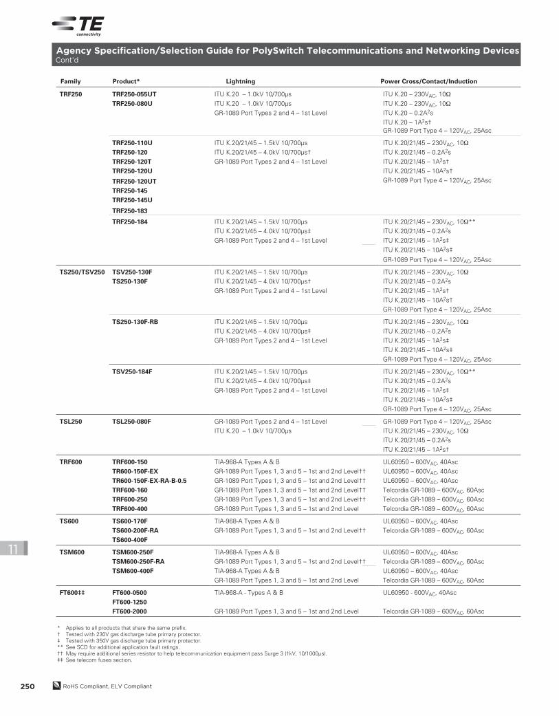
Agency Specification/Selection Guide for PolySwitch Telecommunications and Networking Devices Cont’d
Family Product* Lightning Power Cross/Contact/Induction
* Applies to all products that share the same prefix.
† Tested with 230V gas discharge tube primary protector.
‡ Tested with 350V gas discharge tube primary protector.
** See SCD for additional application fault ratings.
†† May require additional series resistor to help telecommunication equipment pass Surge 3 (1kV, 10/1000µs).
‡‡ See telecom fuses section.
TRF250 TRF250-055UT ITU K.20 – 1.0kV 10/700µs ITU K.20 – 230VAC, 10Ω
TRF250-080U ITU K.20 – 1.0kV 10/700µs ITU K.20 – 230VAC, 10Ω
GR-1089 Port Types 2 and 4 – 1st Level ITU K.20 – 0.2A2s
ITU K.20 – 1A2s†
GR-1089 Port Type 4 – 120VAC, 25Asc
TRF250-110U ITU K.20/21/45 – 1.5kV 10/700µs ITU K.20/21/45 – 230VAC, 10Ω
TRF250-120 ITU K.20/21/45 – 4.0kV 10/700µs† ITU K.20/21/45 – 0.2A2s
TRF250-120T GR-1089 Port Types 2 and 4 – 1st Level ITU K.20/21/45 – 1A2s†
TRF250-120U ITU K.20/21/45 – 10A2s†
TRF250-120UT GR-1089 Port Type 4 – 120VAC, 25Asc
TRF250-145
TRF250-145U
TRF250-183
TRF250-184 ITU K.20/21/45 – 1.5kV 10/700µs ITU K.20/21/45 – 230VAC, 10Ω**
ITU K.20/21/45 – 4.0kV 10/700µs‡ ITU K.20/21/45 – 0.2A2s
GR-1089 Port Types 2 and 4 – 1st Level ITU K.20/21/45 – 1A2s‡
ITU K.20/21/45 – 10A2s‡
GR-1089 Port Type 4 – 120VAC, 25Asc
TS250/TSV250 TSV250-130F ITU K.20/21/45 – 1.5kV 10/700µs ITU K.20/21/45 – 230VAC, 10Ω
TS250-130F ITU K.20/21/45 – 4.0kV 10/700µs† ITU K.20/21/45 – 0.2A2s
GR-1089 Port Types 2 and 4 – 1st Level ITU K.20/21/45 – 1A2s†
ITU K.20/21/45 – 10A2s†
GR-1089 Port Type 4 – 120VAC, 25Asc
TS250-130F-RB ITU K.20/21/45 – 1.5kV 10/700µs ITU K.20/21/45 – 230VAC, 10Ω
ITU K.20/21/45 – 4.0kV 10/700µs‡ ITU K.20/21/45 – 0.2A2s
GR-1089 Port Types 2 and 4 – 1st Level ITU K.20/21/45 – 1A2s‡
ITU K.20/21/45 – 10A2s‡
GR-1089 Port Type 4 – 120VAC, 25Asc
TSV250-184F ITU K.20/21/45 – 1.5kV 10/700µs ITU K.20/21/45 – 230VAC, 10Ω**
ITU K.20/21/45 – 4.0kV 10/700µs‡ ITU K.20/21/45 – 0.2A2s
GR-1089 Port Types 2 and 4 – 1st Level ITU K.20/21/45 – 1A2s‡
ITU K.20/21/45 – 10A2s‡
GR-1089 Port Type 4 – 120VAC, 25Asc
TSL250 TSL250-080F GR-1089 Port Types 2 and 4 – 1st Level GR-1089 Port Type 4 – 120VAC, 25Asc
ITU K.20 – 1.0kV 10/700µs ITU K.20/21/45 – 230VAC, 10Ω
ITU K.20/21/45 – 0.2A2s
ITU K.20/21/45 – 1A2s†
TRF600 TRF600-150 TIA-968-A Types A & B UL60950 – 600VAC, 40Asc
TR600-150F-EX GR-1089 Port Types 1, 3 and 5 – 1st and 2nd Level†† UL60950 – 600VAC, 40Asc
TR600-150F-EX-RA-B-0.5 GR-1089 Port Types 1, 3 and 5 – 1st and 2nd Level†† UL60950 – 600VAC, 40Asc
TRF600-160 GR-1089 Port Types 1, 3 and 5 – 1st and 2nd Level†† Telcordia GR-1089 – 600VAC, 60Asc
TRF600-250 GR-1089 Port Types 1, 3 and 5 – 1st and 2nd Level†† Telcordia GR-1089 – 600VAC, 60Asc
TRF600-400 GR-1089 Port Types 1, 3 and 5 – 1st and 2nd Level Telcordia GR-1089 – 600VAC, 60Asc
TS600 TS600-170F TIA-968-A Types A & B UL60950 – 600VAC, 40Asc
TS600-200F-RA GR-1089 Port Types 1, 3 and 5 – 1st and 2nd Level†† Telcordia GR-1089 – 600VAC, 60Asc
TS600-400F
TSM600 TSM600-250F TIA-968-A Types A & B UL60950 – 600VAC, 40Asc
TSM600-250F-RA GR-1089 Port Types 1, 3 and 5 – 1st and 2nd Level†† Telcordia GR-1089 – 600VAC, 60Asc
TSM600-400F TIA-968-A Types A & B UL60950 – 600VAC, 40Asc
GR-1089 Port Types 1, 3 and 5 – 1st and 2nd Level Telcordia GR-1089 – 600VAC, 60Asc
FT600‡‡ FT600-0500 TIA-968-A - Types A & B UL60950 - 600VAC, 40Asc
FT600-1250
FT600-2000 GR-1089 Port Types 1, 3 and 5 – 1st and 2nd Level Telcordia GR-1089 – 600VAC, 60Asc
* 250VAC interrupt products may help equipment pass ITU K.20, K.21 and K.45 recommendations and Telcordia GR-1089 Port Type 2 and 4 requirements.† 600VAC interrupt products may help equipment pass UL60950, TIA-968-A and GR1089 Port Type 1, 3 and 5 requirements.‡ Product is not currently available in a resistance matched or sorted option.
Table T2Thermal Derating for PolySwitch Telecommunications and Networking Devices[Hold Current (A) at Ambient Temperature (°C)]
Figure T1 Thermal Derating [Hold Current (A) at Ambient Temperature (°C)]
2013_CP_S11-Poly-8-TeleNetwork.indd 252 8/3/13 10:41 AM
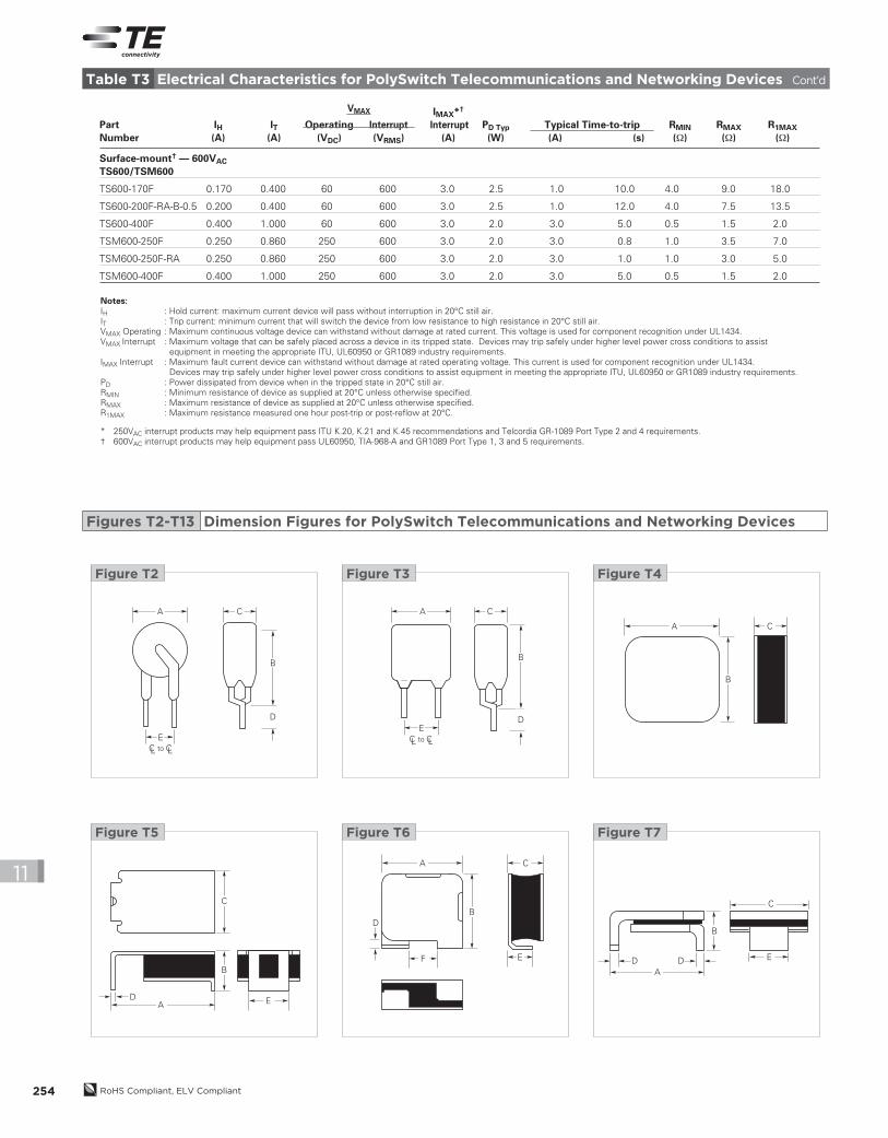
Notes:IH : Hold current: maximum current device will pass without interruption in 20°C still air.IT : Trip current: minimum current that will switch the device from low resistance to high resistance in 20°C still air.VMAX Operating : Maximum continuous voltage device can withstand without damage at rated current. This voltage is used for component recognition under UL1434.VMAX Interrupt : Maximum voltage that can be safely placed across a device in its tripped state. Devices may trip safely under higher level power cross conditions to assist
equipment in meeting the appropriate ITU, UL60950 or GR1089 industry requirements.IMAX Interrupt : Maximum fault current device can withstand without damage at rated operating voltage. This current is used for component recognition under UL1434. Devices may trip safely under higher level power cross conditions to assist equipment in meeting the appropriate ITU, UL60950 or GR1089 industry requirements.PD : Power dissipated from device when in the tripped state in 20°C still air.RMIN : Minimum resistance of device as supplied at 20°C unless otherwise specified.RMAX : Maximum resistance of device as supplied at 20°C unless otherwise specified.R1MAX : Maximum resistance measured one hour post-trip or post-reflow at 20°C.
* 250VAC interrupt products may help equipment pass ITU K.20, K.21 and K.45 recommendations and Telcordia GR-1089 Port Type 2 and 4 requirements.† 600VAC interrupt products may help equipment pass UL60950, TIA-968-A and GR1089 Port Type 1, 3 and 5 requirements.
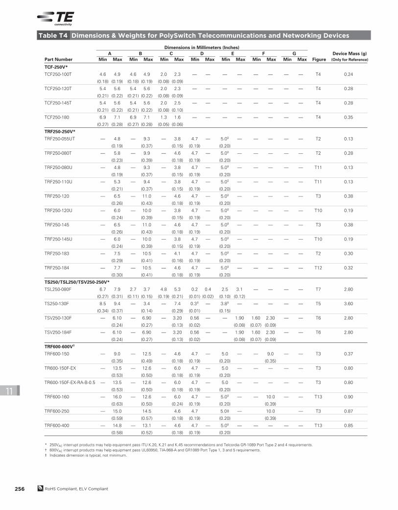
* 250VAC interrupt products may help equipment pass ITU K.20, K.21 and K.45 recommendations and Telcordia GR-1089 Port Type 2 and 4 requirements.† 600VAC interrupt products may help equipment pass UL60950, TIA-968-A and GR1089 Port Type 1, 3 and 5 requirements.‡ Indicates dimension is typical, not minimum.
Part Number
A
Min Max Figure
Device Mass (g)
(Only for Reference)
B
Min Max
C
Min Max
D
Min Max
E
Min Max
F
Min Max
G
Min Max
Dimensions in Millimeters (Inches)
2013_CP_S11-Poly-8-TeleNetwork.indd 256 8/3/13 10:41 AM
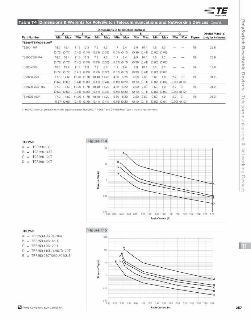
† 600VAC interrupt products may help equipment pass UL60950, TIA-968-A and GR1089 Port Type 1, 3 and 5 requirements.
Part Number
A
Min Max Figure
Device Mass (g)
(Only for Reference)
B
Min Max
C
Min Max
D
Min Max
E
Min Max
F
Min Max
G
Min Max
Dimensions in Millimeters (Inches)
2013_CP_S11-Poly-8-TeleNetwork.indd 257 8/3/13 10:41 AM
RoHS Compliant, ELV Compliant258
11
Tim
e–to
–Tri
p (
s)
Fault Current (A)
1000
100
10
1
0.1
0.010 1 2 3 4 5 6 7
E
C
B
A
D
E
A
BC
D
Figure T17TRF600/TS600/TSM600
A = TRF600-400/TS600-400/
TSM600-400F
B = TRF600-250/TSM600-250F/
TS600-170F/200F
C = TRF600-160
D = TR600-150F-EX
E = TRF600-150
Operating temperature range for all listed products is -40°C to 85°C, except for TRF250-080T and TRF250-184 (0°C to 85°C)
TCF250*
Terminal Material Nickel-plated Copper Foil
Test Conditions
Passive Aging 60°C, 1000 hrs 85°C, 1000 hrsHumidity Aging 85°C, 85% RH, 1000 hrsThermal Shock 125°C, -55°C (10 Times)Solvent Resistance MIL-STD-202, Method 215FNote: Storage conditions: 40°C (max), 70% RH (max), devices should remain in original sealed bag prior to use. Devices may not meet specified values if these storage conditions
are exceeded.
Physical Characteristics
Environmental Specifications
Table T5Physical Characteristics and Environmental Specifications for PolySwitch Telecommunications and Networking Devices
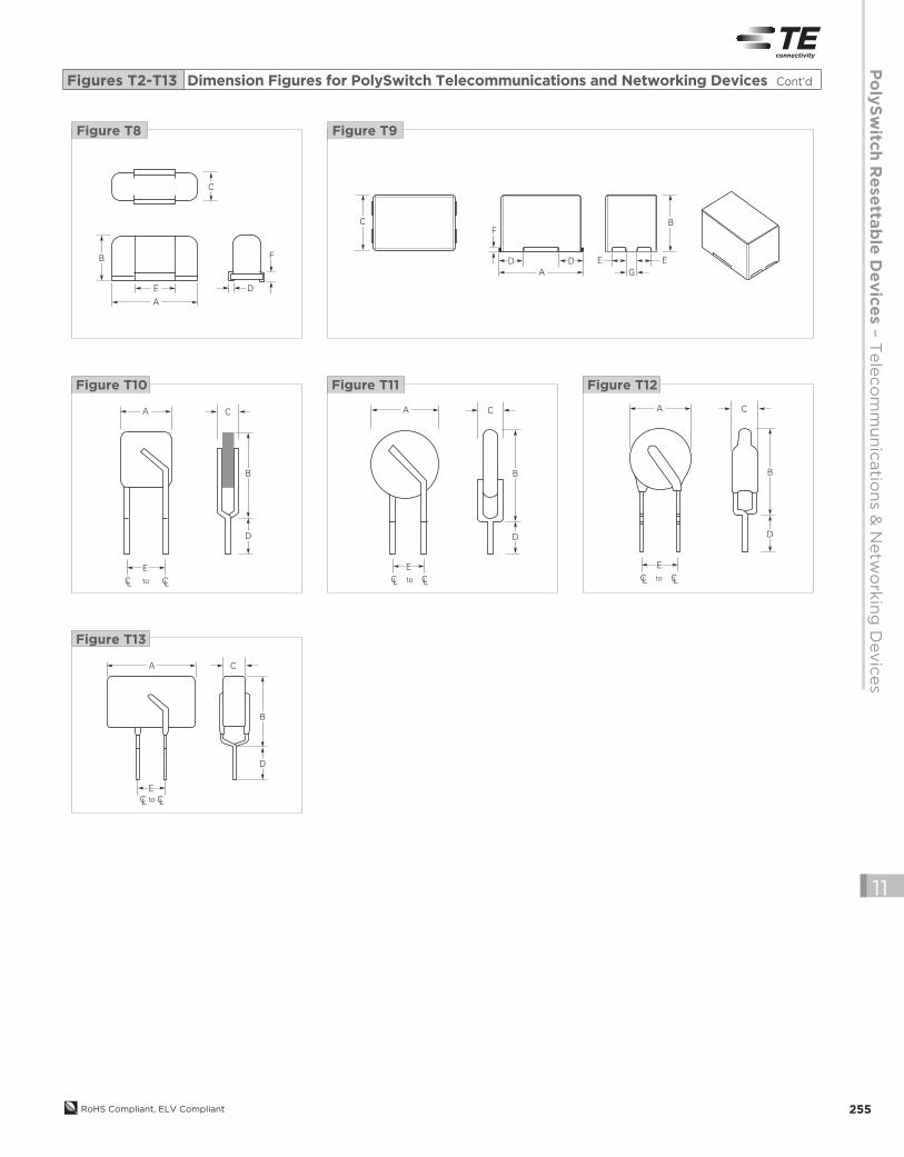
Figures T14-T17
Typical Time-to-Trip Curves at 20°C for PolySwitch Telecommunications and Networking Devices Cont’d
0.00 0.50 1.00 1.50 2.00 2.50 3.00
Tim
e–to
–T
rip
(s)
Fault Current (A)
B
C
D
A
B
DA
C
Figure T16TS250/TSV250/TSL250
A = TSV250-184F
B = TSV250-130F
C = TS250-130F
D = TSL250-080F
2013_CP_S11-Poly-8-TeleNetwork.indd 258 8/3/13 10:41 AM
Po
lyS
witc
h R
ese
ttab
le D
evic
es –
Tele
co
mm
un
icatio
ns &
Netw
ork
ing
Devic
es
RoHS Compliant, ELV Compliant 259
11
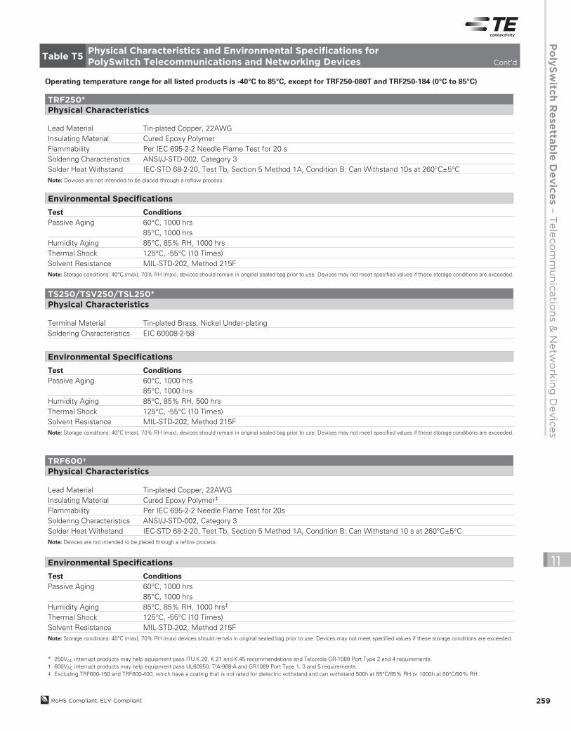
Terminal Material Tin-plated Brass, Nickel Under-platingSoldering Characteristics EIC 60008-2-58
Test Conditions
Passive Aging 60°C, 1000 hrs 85°C, 1000 hrsHumidity Aging 85°C, 85% RH, 500 hrsThermal Shock 125°C, -55°C (10 Times)Solvent Resistance MIL-STD-202, Method 215FNote: Storage conditions: 40°C (max), 70% RH (max), devices should remain in original sealed bag prior to use. Devices may not meet specified values if these storage conditions are exceeded.
TS250/TSV250/TSL250*
Physical Characteristics
Environmental Specifications
* 250VAC interrupt products may help equipment pass ITU K.20, K.21 and K.45 recommendations and Telcordia GR-1089 Port Type 2 and 4 requirements.† 600VAC interrupt products may help equipment pass UL60950, TIA-968-A and GR1089 Port Type 1, 3 and 5 requirements.‡ Excluding TRF600-150 and TRF600-400, which have a coating that is not rated for dielectric withstand and can withstand 500h at 85°C/85% RH or 1000h at 60°C/90% RH.
Lead Material Tin-plated Copper, 22AWGInsulating Material Cured Epoxy Polymer‡
Flammability Per IEC 695-2-2 Needle Flame Test for 20sSoldering Characteristics ANSI/J-STD-002, Category 3Solder Heat Withstand IEC-STD 68-2-20, Test Tb, Section 5 Method 1A, Condition B: Can Withstand 10 s at 260°C±5°CNote: Devices are not intended to be placed through a reflow process.
Thermal Shock 125°C, -55°C (10 Times)Solvent Resistance MIL-STD-202, Method 215FNote: Storage conditions: 40°C (max), 70% RH (max) devices should remain in original sealed bag prior to use. Devices may not meet specified values if these storage conditions are exceeded.
Environmental Specifications
Operating temperature range for all listed products is -40°C to 85°C, except for TRF250-080T and TRF250-184 (0°C to 85°C)
Table T5Physical Characteristics and Environmental Specifications for PolySwitch Telecommunications and Networking Devices Cont’d
Lead Material Tin-plated Copper, 22AWGInsulating Material Cured Epoxy PolymerFlammability Per IEC 695-2-2 Needle Flame Test for 20 sSoldering Characteristics ANSI/J-STD-002, Category 3Solder Heat Withstand IEC-STD 68-2-20, Test Tb, Section 5 Method 1A, Condition B: Can Withstand 10s at 260°C±5°CNote: Devices are not intended to be placed through a reflow process.
Test Conditions
Passive Aging 60°C, 1000 hrs 85°C, 1000 hrsHumidity Aging 85°C, 85% RH, 1000 hrsThermal Shock 125°C, -55°C (10 Times)Solvent Resistance MIL-STD-202, Method 215FNote: Storage conditions: 40°C (max), 70% RH (max), devices should remain in original sealed bag prior to use. Devices may not meet specified values if these storage conditions are exceeded.
TRF250*
Physical Characteristics
Environmental Specifications
2013_CP_S11-Poly-8-TeleNetwork.indd 259 8/3/13 10:41 AM
RoHS Compliant, ELV Compliant260
11
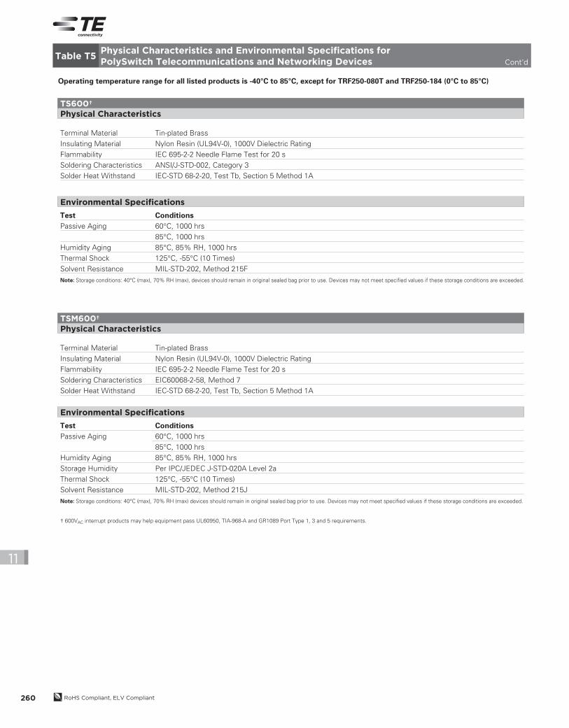
Test Conditions
Passive Aging 60°C, 1000 hrs
85°C, 1000 hrs
Humidity Aging 85°C, 85% RH, 1000 hrs
Storage Humidity Per IPC/JEDEC J-STD-020A Level 2a
Thermal Shock 125°C, -55°C (10 Times)
Solvent Resistance MIL-STD-202, Method 215J
Note: Storage conditions: 40°C (max), 70% RH (max) devices should remain in original sealed bag prior to use. Devices may not meet specified values if these storage conditions are exceeded.
† 600VAC interrupt products may help equipment pass UL60950, TIA-968-A and GR1089 Port Type 1, 3 and 5 requirements.
Terminal Material Tin-plated Brass
Insulating Material Nylon Resin (UL94V-0), 1000V Dielectric Rating
Flammability IEC 695-2-2 Needle Flame Test for 20 s
Operating temperature range for all listed products is -40°C to 85°C, except for TRF250-080T and TRF250-184 (0°C to 85°C)
Table T5Physical Characteristics and Environmental Specifications for PolySwitch Telecommunications and Networking Devices Cont’d
Test Conditions
Passive Aging 60°C, 1000 hrs
85°C, 1000 hrs
Humidity Aging 85°C, 85% RH, 1000 hrs
Thermal Shock 125°C, -55°C (10 Times)
Solvent Resistance MIL-STD-202, Method 215F
Note: Storage conditions: 40°C (max), 70% RH (max), devices should remain in original sealed bag prior to use. Devices may not meet specified values if these storage conditions are exceeded.
Terminal Material Tin-plated Brass
Insulating Material Nylon Resin (UL94V-0), 1000V Dielectric Rating
Flammability IEC 695-2-2 Needle Flame Test for 20 s
2013_CP_S11-Poly-8-TeleNetwork.indd 260 8/3/13 10:41 AM
Po
lyS
witc
h R
ese
ttab
le D
evic
es –
Tele
co
mm
un
icatio
ns &
Netw
ork
ing
Devic
es
RoHS Compliant, ELV Compliant 261
11
Chip* — 250VAC
TCF250
TCF250-100T 2,500 — 10,000 — —
TCF250-120T 2,500 — 10,000 — —
TCF250-145T 2,500 — 10,000 — —
TCF250-180 2,500 — 10,000 — UL
Radial-leaded* — 250VAC
TRF250
TRF250-055UT 500 — 10,000 — —
TRF250-080U 500 — 10,000 — UL, CSA, TÜV
TRF250-080U-2 — 1,500 7,500 — UL, CSA, TÜV
TRF250-080T 500 — 10,000 08F UL, CSA, TÜV
TRF250-110U 500 — 10,000 — UL, CSA, TÜV
TRF250-120 500 — 10,000 20F UL, CSA, TÜV
TRF250-120-2 — 1,500 7,500 20F UL, CSA, TÜV
TRF250-120T 500 — 10,000 20F UL, CSA, TÜV
TRF250-120T-2 — 1,500 7,500 20F UL, CSA, TÜV
TRF250-120U 500 — 10,000 20F UL, CSA, TÜV
TRF250-120U-2 — 1,500 7,500 20F UL, CSA, TÜV
TRF250-120UT 500 — 10,000 20F UL, CSA, TÜV
TRF250-145 500 — 10,000 45F UL, CSA, TÜV
TRF250-145-2 — 1,500 7,500 45F UL, CSA, TÜV
TRF250-145-RA 500 — 10,000 45F UL, CSA, TÜV
TRF250-145U 500 — 10,000 45F UL, CSA, TÜV
TRF250-145U-2 — 1,500 7,500 45F UL, CSA, TÜV
TRF250-183 500 — 10,000 83F UL, CSA, TÜV
TRF250-183-2 — 1,500 7,500 83F UL, CSA, TÜV
TRF250-184 500 — 10,000 84F UL, CSA, TÜV
Surface-mount* — 250VAC
TS250/TSL250/TSV250
TSL250-080F-2 — 1,500 7,500 T08 UL, CSA,TÜV
TS250-130F-2 — 1,500 7,500 T13 UL, CSA, TÜV
TSV250-130F-2 — 1,200 6,000 T13V UL, CSA, TÜV
TSV250-184F 2500 — 10,000 T18V UL
Radial-leaded† — 600VAC
TRF600
TRF600-150 500 — 10,000 150F UL, CSA, TÜV
TRF600-150-2 — 1,500 7,500 150F UL, CSA, TÜV
TR600-150F-EX 500 — 10,000 150F UL, CSA
TR600-150F-EX-2 — 600 3,000 150F UL, CSA
TR600-150F-EX-RA-B-0.5 500 — 10,000 150F UL, CSA
TRF600-160 500 — 10,000 160F UL, CSA, TÜV
TRF600-160-2 — 600 3,000 160F UL, CSA, TÜV
TRF600-250 500 — 10,000 250F UL, CSA, TÜV
TRF600-400 500 — 10,000 400F UL, CSA
Surface-mount† — 600VAC
TS600/TSM600
TS600-170F-2 — 300 900 T20 UL, CSA
TS600-200F-RA-2 — 300 900 T20 UL, CSA
TS600-400F-2 — 300 900 T40 UL, CSA
TSM600-250F-2 — 200 1,000 TSM600 UL, CSA
TSM600-250F-RA-2 — 200 1,000 TSM600 UL, CSA
TSM600-400F-2 — 200 1,000 TSM600 UL
Part NumberBag
QuantityTape and Reel
QuantityStandard Package
Quantity Part Marking Agency Recognition
* 250VAC interrupt products are designed to help equipment pass ITU K.20, K.21 and K.45 recommendations and Telcordia GR-1089 Port Type 2 and 4 requirements.† 600VAC interrupt products are designed to help equipment pass UL60950, TIA-968-A and GR1089 Port Type 1, 3 and 5 requirements.
Table T6Packaging and Marking Information for PolySwitch Telecommunications and Networking Devices
2013_CP_S11-Poly-8-TeleNetwork.indd 261 8/3/13 10:41 AM
RoHS Compliant, ELV Compliant262
11
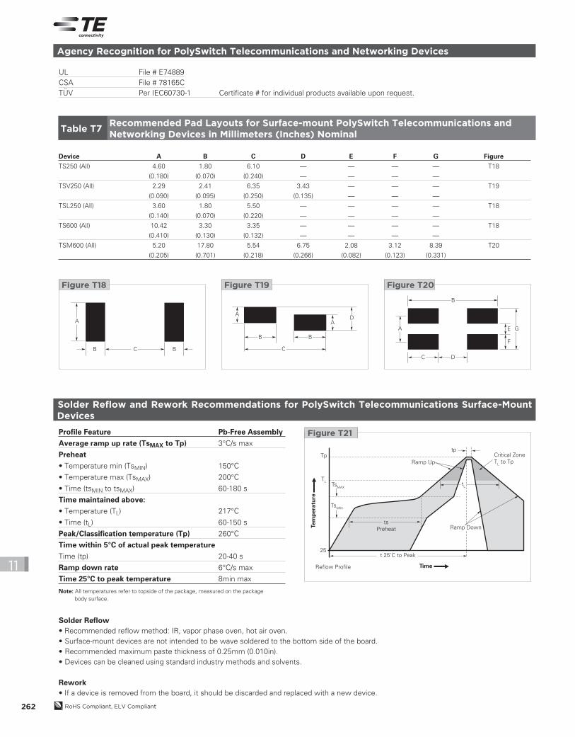
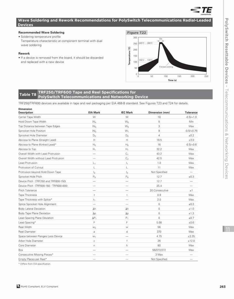
Solder Reflow and Rework Recommendations for PolySwitch Telecommunications Surface-Mount Devices
Solder Reflow
• Recommended reflow method: IR, vapor phase oven, hot air oven.• Surface-mount devices are not intended to be wave soldered to the bottom side of the board.• Recommended maximum paste thickness of 0.25mm (0.010in).• Devices can be cleaned using standard industry methods and solvents.
Rework
• If a device is removed from the board, it should be discarded and replaced with a new device.
Profile Feature Pb-Free Assembly
Average ramp up rate (TsMAX to Tp) 3°C/s max
Preheat
• Temperature min (TsMIN) 150°C
• Temperature max (TsMAX) 200°C
• Time (tsMIN to tsMAX) 60-180 s
Time maintained above:
• Temperature (TL) 217°C
• Time (tL) 60-150 s
Peak/Classification temperature (Tp) 260°C
Time within 5°C of actual peak temperature
Time (tp) 20-40 s
Ramp down rate 6°C/s max
Time 25°C to peak temperature 8min max
Critical Zone
TL to TpRamp Up
t 25˚C to Peak
Reflow Profile Time
Ramp Downts
Preheat
TsMAX
TL
Tptp
25
TsMIN
tL
Tem
pera
ture
Figure T21
Note: All temperatures refer to topside of the package, measured on the package body surface.
Agency Recognition for PolySwitch Telecommunications and Networking Devices
UL File # E74889CSA File # 78165CTÜV Per IEC60730-1 Certificate # for individual products available upon request.
Part Numbering System for PolySwitch Surface-mount Telecommunications and Networking Devices
TSx -200 F -RA -B-0.5 -2
Packaging2 = Tape and Reel(Blank) = Bulk
B-x.x = Resistance Matched in Bins of x.xΩ (Optional)
Rx = Resistance Range (Optional)
F = RoHS Compliant, ELV Compliant
Hold Current (mA)
Product Series (TS250, TSV250, TSL250, TS600, TSM600)
2013_CP_S11-Poly-8-TeleNetwork.indd 267 8/3/13 10:41 AM
RoHS Compliant, ELV Compliant268
11
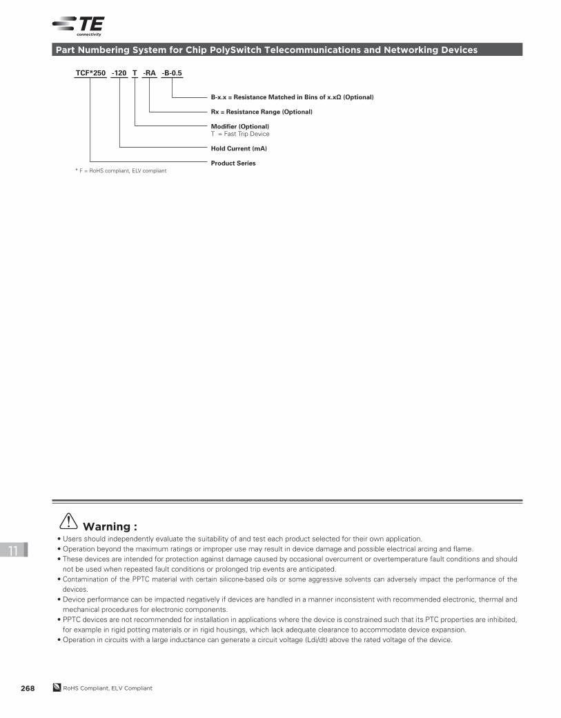
Part Numbering System for Chip PolySwitch Telecommunications and Networking Devices
TCF*250 -120 T -RA -B-0.5
B-x.x = Resistance Matched in Bins of x.xΩ (Optional)
Rx = Resistance Range (Optional)
Modifier (Optional)T = Fast Trip Device
Hold Current (mA)
Product Series* F = RoHS compliant, ELV compliant
Warning :• Users should independently evaluate the suitability of and test each product selected for their own application.• Operation beyond the maximum ratings or improper use may result in device damage and possible electrical arcing and flame.• These devices are intended for protection against damage caused by occasional overcurrent or overtemperature fault conditions and should
not be used when repeated fault conditions or prolonged trip events are anticipated.• Contamination of the PPTC material with certain silicone-based oils or some aggressive solvents can adversely impact the performance of the
devices.• Device performance can be impacted negatively if devices are handled in a manner inconsistent with recommended electronic, thermal and
mechanical procedures for electronic components.• PPTC devices are not recommended for installation in applications where the device is constrained such that its PTC properties are inhibited,
for example in rigid potting materials or in rigid housings, which lack adequate clearance to accommodate device expansion.• Operation in circuits with a large inductance can generate a circuit voltage (Ldi/dt) above the rated voltage of the device.
2013_CP_S11-Poly-8-TeleNetwork.indd 268 8/3/13 10:41 AM