La pompa a pistoni assiali a cilindrata variabile OMFB è di tipo a piatto oscillante.La cilindrata della pompa dipende dalla corsa dei pistoni pompanti, che a sua volta dipende dall’inclinazione del piatto oscillante. La pompa all’avviamento si trova in cilindrata massima per effetto di due molle che spingono il piatto oscillante. La cilindrata della pompa viene ridotta agendo su due pistoni comandati idraulicamente in grado di vincere la forza delle molle. Un corpo cilindri ruota solidale con l’albero e costringe i pistoni a ruotare anch’essi alla stessa velocità dell’albero ed a compiere il percorso circolare sul piatto oscillante che ne provoca il movimento alternativo. La pompa in questo modo è in grado di erogare portata dal valore massimo fino ad un valore nullo.La variazione della cilindrata è comandata dal regolatore che si trova montato sulla pompa stessa.Sono pompe adatte a funzionare in circuito aperto. Permettono di avere tempi di reazione brevi e, grazie alla loro larghezza ridotta, il montaggio diretto sulle prese di forza (PTO) dei veicoli commerciali.In fase d’ordine è necessario specificare il senso di rotazione della pompa.
The OMFB variable displacement axial piston pump has got a swash plate.The displacement of the pump depends on the stroke of the pistons, which is determined by the inclination of the swash plate. At the start, the pump is at its maximum displacement position because of the springs pushing against the swash plate. The displace-ment of the pump is reduced by means of two pistons hydraulically operated that win the force of the springs. The cylinders block rotates together with the shaft forcing the pistons to rotate at the same speed of the shaft and make a circular path on the swash plate that causes the reciprocating movement. In this way, the pump is able to deliver from the maximum to zero flow rate. The variation of the displacement is controlled by a regulator, which is fitted on the pump itself. These pumps are designed to operate in open circuit. They allow very quick reaction time and thanks to its compact size they can be coupled directly onto PTO’s of commer-cial vehicles. When ordering please specific the required direction of rotation.
POMPE A CILINDRATA VARIABILE
VARIABLE DISPLACEMENT PUMPS
FAMIGLIAFAMILY
PPV 60PPV 75PPV 90PPV 110
CODICE CODE
LS D
D
P
S
LS BLOCCHETTO LS/ LS BLOCK
D DRENAGGIO / DRAIN
P PRESSIONE / PRESSURE
S ASPIRAZIONE / SUCTION
Pompa rotazione DESTRARIGHT Hand rotating pump
Pompa rotazione SINISTRALEFT Hand rotating pump
Cod
ice
fogl
io:9
97-1
08-0
6010
Rev
:AD
D
ata:
Mer
cole
dì 2
5 ot
tobr
e 20
17
108-060
pag.4O.M.F.B. S.p.A. Hydraulic ComponentsWe reserve the right to make any changes without notice.
Edition 2016.08 No reproduction, however partial, is permitted.Via Cave, 7/9 25050 Provaglio d’Iseo (Brescia) Italy Tel.: +39.030.9830611
375 bar 400 bar 375 bar 400 bar 375 bar 400 bar 375 bar 400 bar
Pressione d’ingresso assoluta necessaria nel circuito apertoAbsolute inlet pressure required in open circuit 0,85 bar
Pressione massima ammissibile sul corpo (statica/dinamica)Max. permissible housing pressure (static/dynamic) 3 bar
Pressione d’ingresso massima ammissibileMax. permissible inlet pressure (static/dynamic) 2 bar
Numero di giri max. con angolo di regolazione max.a una pressione d’ingresso assoluta di 1 bar. / Max. speed during suction operation and max. swash plate angle at 1 bar abs. Inlet pressure
2500 rpm 2400 rpm 2300 rpm 2200 rpm
Numero giri max. in annullamento e pressione d’ingresso assoluta 1bar.Max. speed with zero stroke and 1 bar abs. Inlet pressure 3000 rpm
Numero di giri minimo in funzionamento continuoMin. speed in continuous operation 500 rpm
Coppia motrice necessaria a 100 barRequired drive torque at 100 bar 100 Nm 125 Nm 150 Nm 185 Nm
Potenza motrice a 250 bar e 2.000 rpmDrive power at 250 bar and 2000 rpm 53 kW 80 kW 100 kW 120 kW
Peso / Weight 24 Kg 26 Kg 29 Kg 30 Kg
POMPE A CILINDRATA VARIABILE / VARIABLE DISPLACEMENT PUMPS
Cod
ice
fogl
io:9
97-1
08-0
6010
Rev
:AD
D
ata:
Mer
cole
dì 2
5 ot
tobr
e 20
17
CODICI ORDINAZIONE / ORDER CODES
PPV 60 PPV 60ADJUSTABLE PPV 75 PPV 90 PPV 110
108-060-00625 sinistra/left
108-060-20621sinistra/left
108-060-00778sinistra/left
108-060-00929sinistra/left
108-060-01124sinistra/left
108-060-00634destra/right
108-060-20630destra/right
108-060-00787destra/right
108-060-00938destra/right
108-060-01133destra/right
0
100
200
300
400
500
600
700
0 50 100 150 200 250 300 350
T [N
m]
�p [bar]
COPPIA ASSORBITA (DRIVE TORQUE)
PPV 110
PPV 90
PPV 75
PPV 60
020406080
100120140160180200220240260280300
0 500 1000 1500 2000 2500
Q [l
pm]
Speed [rpm]
PORTATA (FLOW)
PPV 110
PPV 90
PPV 75
PPV 60
La cilindrata 75 cc evidenziata in colore più scuro, non è attualmente disponibile.75 cc pump displacement in dark background isn’t available yet.
pag.5O.M.F.B. S.p.A. Hydraulic ComponentsWe reserve the right to make any changes without notice.
Edition 2016.08 No reproduction, however partial, is permitted.Via Cave, 7/9 25050 Provaglio d’Iseo (Brescia) Italy Tel.: +39.030.9830611
Viscosità cinematica max consentita all’avviamento / Max kinematic viscosity suggested at the start-up VG= 750 cStIndice di viscosità consigliato / Viscosity index suggested VI > 100
POMPE A CILINDRATA VARIABILE / VARIABLE DISPLACEMENT PUMPS
0
10
20
30
40
50
60
70
80
0 20 40 60 80 100 120
[kW
]
Q [lpm]
PPV60 - POTENZA ASSORBITA (POWER INPUT)
350
300
250
200
150
100
Δp [bar]
0
20
40
60
80
100
120
0 20 40 60 80 100 120 140 160 180
[kW
]
Q [lpm]
PPV90 - POTENZA ASSORBITA (POWER INPUT) Δp [bar]
350
300
250
200
150
100
0
20
40
60
80
100
120
140
0 20 40 60 80 100 120 140 160 180 200 220
[kW
]
Q [lpm]
PPV110 - POTENZA ASSORBITA (POWER INPUT)
0
20
40
60
80
100
0 20 40 60 80 100 120 140 160
[kW
]
Q [lpm]
PPV75 - POTENZA ASSORBITA (POWER INPUT)
Δp [bar]
Δp [bar]
350
300
250
200
150
100
350
300
250
200
150
100
/ Nominal values
Flow
Torque
Power
/ displacement
/ pressure drop
/ rotation speed
/ volumetric efficiency
/ hydro-mechanic efficiency
/ overall efficiency
FORMULE / FORMULAS
pag.6O
.M.F.B. S.p.A
. Hydraulic C
omponents
We reserve the right to m
ake any changes without notice.
Edition 2016.08 No reproduction, how
ever partial, is permitted.
Via Cave, 7/9 25050 Provaglio d’Iseo (Brescia) Italy Tel.: +
39.030.9830611Fax: +
39.030.9839207-208 Internet:ww
w.om
fb.it e-mail:info@
omfb.it
ING
OM
BR
O P
PV
60 / P
PV
60 D
IMEN
SION
S
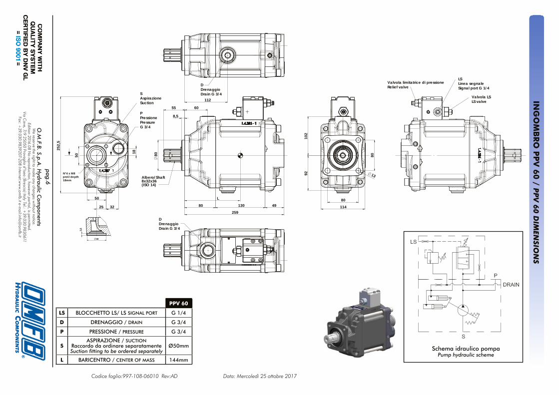
Albero/Shaft8x32x36(ISO 14)
49
55
80
259
130
80
8,5
60
L
50
80
102
92
80
13
114
PPressionePressureG 3/4
252,
5
18
25 32
DDrenaggioDrain G 3/4
112
DDrenaggioDrain G 3/4
LSLinea segnale Signal port G 1/4
SAspirazioneSuction
Valvola limitatrice di pressioneRelief valve
Valvola LSLS valve
50
N°4 x M8prof./depth18mm
58
5,5
Schema idraulico pompaPump hydraulic scheme
Codice foglio:997-108-06010 Rev:AD Data: Mercoledì 25 ottobre 2017
PPV 60
LS BLOCCHETTO LS/ LS SIGNAL PORT G 1/4
D DRENAGGIO / DRAIN G 3/4
P PRESSIONE / PRESSURE G 3/4
SASPIRAZIONE / SUCTION
Raccordo da ordinare separatamenteSuction fitting to be ordered separately
Ø50mm
L BARICENTRO / CENTER OF MASS 144mm
pag.7O
.M.F.B. S.p.A
. Hydraulic C
omponents
We reserve the right to m
ake any changes without notice.
Edition 2016.08 No reproduction, how
ever partial, is permitted.
Via Cave, 7/9 25050 Provaglio d’Iseo (Brescia) Italy Tel.: +
39.030.9830611Fax: +
39.030.9839207-208 Internet:ww
w.om
fb.it e-mail:info@
omfb.it
La versione AD
JUSTA
BLE, prevede una vite di regolazione posteriore che lim
ita la cilindrata della pompa a valori
inferiori a quella nominale.
The AD
JUSTA
BLE version consists of a rear setting screw
that limits the displacem
ent of the pumps to low
er values than the nom
inal one.
PPV 60 ADJUSTABLE
LS BLOCCHETTO LS/ LS SIGNAL PORT G 1/4
D DRENAGGIO / DRAIN G 3/4
P PRESSIONE / PRESSURE G 3/4
SASPIRAZIONE / SUCTION
Raccordo da ordinare separatamenteSuction fitting to be ordered separately
Ø50mm
V VITE REGOLAZIONE CILINDRATA DISPLACEMENT SETTING SCREW
L BARICENTRO / CENTER OF MASS 144mm
ING
OM
BR
O P
PV
60 A
DJU
STAB
LE / AD
JUSTA
BLE P
PV
60 D
IMEN
SION
S
Albero/Shaft8x32x36(ISO 14)
49
55
80
259
130
80
8,5
60
L
50
80
102
92
80
13
114
PPressionePressureG 3/4
252,
5
18
25 32
DDrenaggioDrain G 3/4
112
DDrenaggioDrain G 3/4
LSLinea segnale Signal port G 1/4
SAspirazioneSuction
Valvola limitatrice di pressioneRelief valve
Valvola LSLS valve
50
N°4 x M8prof./depth18mm
58
5,5
VVite di regolazione cilindrataDisplacement setting screw
Schema idraulico pompaPump hydraulic scheme
Codice foglio:997-108-06010 Rev:AD Data: Mercoledì 25 ottobre 2017
pag.8O
.M.F.B. S.p.A
. Hydraulic C
omponents
We reserve the right to m
ake any changes without notice.
Edition 2016.08 No reproduction, how
ever partial, is permitted.
Via Cave, 7/9 25050 Provaglio d’Iseo (Brescia) Italy Tel.: +
39.030.9830611Fax: +
39.030.9839207-208 Internet:ww
w.om
fb.it e-mail:info@
omfb.it
PPV 75 PPV 90 PPV 110
LS BLOCCHETTO LS/ LS SIGNAL PORT G 1/4
D DRENAGGIO / DRAIN G 3/4
P PRESSIONE / PRESSURE G 1
SASPIRAZIONE / SUCTION
Raccordo da ordinare separatamenteSuction fitting to be ordered separately
Ø50 mm
L BARICENTRO / CENTER OF MASS 154 mm
ING
OM
BR
O P
PV
75-9
0-1
10 / P
PV
75-9
0-1
10 D
IMEN
SION
S
Schema idraulico pompaPump hydraulic scheme
Codice foglio:997-108-06010 Rev:AD Data: Mercoledì 25 ottobre 2017
270,
5
32 28,5
18
110
80
80127
13
106
106
80
8,5
55 110
89 136 54279
L
DDrenaggioDrain G 3/4
DDrenaggioDrain G 3/4
Valvola limitatrice di pressioneRelief valve
LSLinea segnaleSignal port G 1/4
Valvola LSLS valve
Albero/Shaft8x32x36(ISO14)
SAspirazioneSuction
PPressionePressureG 1
pag.9O.M.F.B. S.p.a. Hydraulic ComponentsWe reserve the right to make any changes without notice.
Edition 2016.08 No reproduction, however partial, is permitted.Via Cave, 7/9 25050 Provaglio d’Iseo (Brescia) Italy Tel.: +39.030.9830611
ISTRUZIONI PER L’AVVIAMENTO DELLE POMPE A CILINDRATA VARIABILE
START-UP GUIDE FOR VARIABLE DISPLACEMENT PUMPS
- Le pompe PPV sono idonee al montaggio diretto su PTO con flangiatura ISO 7653.- Prima dell’installazione della pompa verificare che il senso di rotazione sia corretto. - La pompa può essere montata in orizzontale od in verticale (con l’albero rivolto verso l’alto). - In caso di montaggio della pompa in orizzontale utilizzare sempre il drenaggio superiore e far si che il tubo che arriva nel serbatoio sia sempre immerso in olio.- In caso di montaggio della pompa in verticale utilizzare sempre il drenaggio superiore. In questo caso collegare inoltre al drenaggio anche lo sfiato (viene realizzato solo per le pompe con montaggio verticale). Specificare in fase d’ordine se la pompa deve essere montata in verticale. - Disporre i tubi in modo da evitare la formazione di vuoti d’aria e per consentire una corretta disareazione dell’olio. - Il tubo di drenaggio deve avere diametro minimo di G 3/4 e collegare direttamente la pompa al serbatoio.- La pompa può essere montata direttamente dentro al serbatoio.- Provvedere all’installazione di un filtro idoneo a garantire che la pompa lavori con un fluido con classe di purezza 19/17/14 secondo ISO4406.- La pompa non può essere installata al di sopra del livello dell’olio. Assicurarsi che sia posizionata almeno 200 mm al di sotto del livello minimo dell’olio del serbatoio dell’olio.- L’olio che giunge alla pompa deve essere sufficientemente disareato in modo da non far insorgere problemi sull’aspirazione della pompa stessa.- L’impianto deve essere dotato di una valvola limitatrice di pressione installata in prossimità della pompa stessa in modo da garantire un rapido intervento.- L’impianto deve essere dotato di un opportuno sistema di raffreddamento su un circuito separato.- Prima della messa in funzione della pompa procedere al riempimento della stessa con olio idraulico ed al successivo spurgo dell’aria.- In presenza di bassa temperatura la pompa deve essere azionata senza carico finché l’olio non raggiunge una viscosità accettabile.- Al primo avviamento far funzionare la pompa per almeno 10 minuti ad una pressione compresa tra 50 e 100 bar.- Non smontare la pompa senza prima aver contattato il servizio tecnico-commerciale di OMFB.
REGOLATORE LOAD SENSING LS (vedi disegno ingombro)Regolare la pressione differenziale ∆p = pressione impianto meno pressione segnale.L’intervallo di regolazione è 15-50 bar.Settaggio preimpostato 30 bar.Regolazione 15 bar/rev.---Regolare la pressione max. dell’impianto fra 20 e 350 bar.Il valore preimpostato della valvola limitatrice di pressione è di 330 bar.Regolazione 150 bar/rev.
La capacità della linea di segnale LS deve adattarsi al relativo impianto idraulico. La linea di segnale deve essere preferibilmente costituita da un tubo flessibile di diametro idoneo a garantire lo smorzamento di eventuali fluttua-zioni del segnale LS.
LSLinea segnale Signal port G 1/4
Valvola limitatrice di pressioneRelief valve
Valvola LSLS valve
Cod
ice
fogl
io:9
97-1
08-0
6010
Rev
:AD
D
ata:
Mer
cole
dì 2
5 ot
tobr
e 20
17
pag.10O.M.F.B. S.p.A. Hydraulic ComponentsWe reserve the right to make any changes without notice.
Edition 2016.08 No reproduction, however partial, is permitted.Via Cave, 7/9 25050 Provaglio d’Iseo (Brescia) Italy Tel.: +39.030.9830611
- The PPV pumps allow a direct coupling onto PTO’s having ISO 7653 standard flange.- Before installation of the pump, make sure the direction of rotation is the correct one.- The pump can be fitted either horizontally or vertically (with shaft pointing upward).- In case of horizontal mounting always use the upper drain port and make sure the oil hose going to tank is discharging under the oil level. - In case of vertical mounting always use the upper drain port. In this case, connect also the breather (used only for vertically mounted pumps). When ordering please specify if the pumps is vertically mounted.- Arrange the hoses in such a way to avoid air gaps and to allow proper oil deareation.- The drain line has to have a minimum diameter of G3/4 and connect directly the pump to tank.- Provide the installation of suitable filter to guarantee the pump to work with fluid having a purity class 19/17/14 according to ISO4406.- The pump cannot be installed above the oil level. Make sure it is fitted at least 200mm lower the oil level of the hydraulic tank.- The oil entering into the pump has to have sufficient deareation in order to avoid problems with suction of the pump itself.- The hydraulic circuit has to be equipped with a pressure relief valve fitted near the pump so as to ensure a quick intervention. - The hydraulic circuit has to be equipped with a proper cooling unit on a separate system.- Before starting up the pump, fill it up with hydraulic oil and bleed the air.- In case of low temperature the pump has to run without load until the oil reaches a proper viscosity.- During its first start up, let the pump run for at least 10 minutes at pressure range between 50 and 100 bar.- Do not disassemble the pump without contacting the OMFB sales/technical support.
LS LOADING SENSING REGULATOR (see dimensional drawing)Regulate the differential pressure ∆p = circuit pressure less signal pressure.The adjustment range is 15-50 bar.Default setting 30 bar.Setting 15 bar/rev.---Adjust the maximum pressure of hydraulic circuit between 20 and 350 bar.The default setting of the pressure relief valve is 330 bar.Setting 150 bar/rev.
The capacity of the LS line has to be adapted to the related hydraulic circuit. The signal line should preferably consist of a flexible hose having suitable diameter to ensure the damping of possible LS signal fluctuations.
LSLinea segnale Signal port G 1/4
Valvola limitatrice di pressioneRelief valve
Valvola LSLS valve
Cod
ice
fogl
io:9
97-1
08-0
6010
Rev
:AD
D
ata:
Mer
cole
dì 2
5 ot
tobr
e 20
17
POMPE A CILINDRATA VARIABILE / VARIABLE DISPLACEMENT PUMPS
pag.11O.M.F.B. S.p.A. Hydraulic ComponentsWe reserve the right to make any changes without notice.
Edition 2016.08 No reproduction, however partial, is permitted.Via Cave, 7/9 25050 Provaglio d’Iseo (Brescia) Italy Tel.: +39.030.9830611
Sbloccare e togliere tutte e 4 le viti dei tiranti mediante brugola. Fra corpo intermedio e finale si forma auto-maticamente una fessura di circa 4-5 mm di larghezza. Separare completamente corpo finale e corpo interme-dio.
Attenzione!Il corpo intermedio non deve staccarsi dal corpo fron-tale, la posizione di smontaggio è verticale con l’albero rivolto verso il basso.
SOSTITUZIONE DEL PIATTO DI DISTRIBUZIONE Il piatto distributore va sbloccato dal blocco cilindri o rispettivamente dal corpo finale. Prima del montaggio depositare 4 gocce di grasso sulla superficie di contatto del nuovo piatto distributore.
Il nuovo piatto distributore va posto nel corpo finale in modo tale che la spina di guida del corpo finale entri n nell’incavo del piatto distributore. La fenditura di pressione con nervature della piastra di distribuzione sta sulla fenditura di pressione del corpo finale. Per invertire il senso di rotazione, il corpo finale va girato con il nuo-vo piatto distributore di 180° intorno all’asse del cuscinetto.Attenzione!La freccia intera formata per metà dal corpo intermedio e metà dal corpo finale indica il nuovo senso di rotazione. L’altra mezza freccia non vale (su un solo lato).
2
3
Attacco aspirazione
Attacco pressione
1
Lato di aspirazione Lato pressione
Tipo pompa Piattodistributore
PPV 60PPV 60ADJ
DX 531-007-00105
SX 531-007-00114
PPV 75DX 531-007-00427
SX 531-007-00418
PPV 90DX 531-007-00329
SX 531-007-00310
PPV 110DX 531-007-00221
SX 531-007-00212
DX = Piastra di distribuzione rotazione destrorsaSX = Piastra di distribuzione rotazione sinistrorsa Lato
• Controllare che le guarnizioni e l’o-ring siano siste-mati correttamente;
• Infilare con cautela il corpo finale sulle molle ad eli-ca del pistone di regolazione e sul perno di banco dell’albero fino all’arresto. Resta una fessura di circa 4-5 mm.
Attenzione!Tutte le parti vanno trattenute solo con la forza delle mani. Montare tutte e 4 le viti tiranti mediante chiave dinamometrica e serrarle in modo incrociato in 3 step:
4
Attacco aspirazione
Attacco pressione
Tipo pompa STEP 1 STEP 2 STEP 3 Tipo viti Chiavebrugola
PPV 60PPV 60ADJ 40 Nm 80 Nm 110 Nm
M12x170 DIN 912-10.9
10
PPV 7590-110 80 Nm 120 Nm 160 Nm
M14x210 UNI 5931
12
Cod
ice
fogl
io:9
97-1
08-0
6010
Rev
:AD
D
ata:
Mer
cole
dì 2
5 ot
tobr
e 20
17
pag.13O.M.F.B. S.p.A. Hydraulic ComponentsWe reserve the right to make any changes without notice.
Edition 2016.08 No reproduction, however partial, is permitted.Via Cave, 7/9 25050 Provaglio d’Iseo (Brescia) Italy Tel.: +39.030.9830611
Loosen all 4 tierod bolts them. A clearance of 4-5 mm opens automatically when loosening the bolts, between the end cover and the center housing. Front and center housing must not be separated.
Attention!Disassemble end cover completely from center housing, best for dismantling is with shaft directing downwards.
CHANGE THE PORT PLATE
The separate the port plate from the rear housing / cylinder block. The new port plate should be mounted with a few spots of grease.
The guide pin in the end cover must fit into the groove of the port plate. The pressure slot (intermittend) has to be placed over the pressure groove of the rear housing (P-port side). The end cover with the new port plate has to be turned around the bearing center for reversing the rotation direction.Attention! The half of an arrow is applied to both center housing and end cover. The new rotation direction is indicated when both halfs from a complete arrow (the one half on the opposite housing side does not apply).
2
3
Suction port
Pressureport
1
Suction side Pressure side
DX = port plate for clockwise rotationSX = port plate for counter rotation Pressure
sideSuctionside
Grease
ROTATION VERSION: CLOCKWISE
ROTATION VERSION: COUNTER-CLOCKWISE
Pressureside
Suction side
Pin bottom
Rear housing rotated by 180° (up-side down) and replace the port plate
Pin top
Pressureside
Suction side
Pump type Port plate
PPV 60PPV 60ADJ
DX 531-007-00105
SX 531-007-00114
PPV 75DX 531-007-00427
SX 531-007-00418
PPV 90DX 531-007-00329
SX 531-007-00310
PPV 110DX 531-007-00221
SX 531-007-00212
Cod
ice
fogl
io:9
97-1
08-0
6010
Rev
:AD
D
ata:
Mer
cole
dì 2
5 ot
tobr
e 20
17
pag.14O.M.F.B. S.p.A. Hydraulic ComponentsWe reserve the right to make any changes without notice.
Edition 2016.08 No reproduction, however partial, is permitted.Via Cave, 7/9 25050 Provaglio d’Iseo (Brescia) Italy Tel.: +39.030.9830611
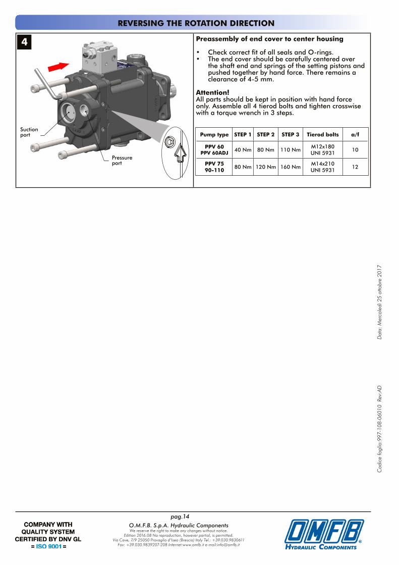
• Check correct fit of all seals and O-rings.• The end cover should be carefully centered over
the shaft end and springs of the setting pistons and pushed together by hand force. There remains a clearance of 4-5 mm.
Attention! All parts should be kept in position with hand force only. Assemble all 4 tierod bolts and tighten crosswise with a torque wrench in 3 steps.
4
Suctionport
Pressureport
REVERSING THE ROTATION DIRECTION
Pump type STEP 1 STEP 2 STEP 3 Tierod bolts a/f
PPV 60PPV 60ADJ 40 Nm 80 Nm 110 Nm
M12x180 UNI 5931
10
PPV 7590-110 80 Nm 120 Nm 160 Nm
M14x210 UNI 5931
12
Cod
ice
fogl
io:9
97-1
08-0
6010
Rev
:AD
D
ata:
Mer
cole
dì 2
5 ot
tobr
e 20
17
pag.15O.M.F.B. S.p.a. Hydraulic ComponentsWe reserve the right to make any changes without notice.
Edition 2016.08 No reproduction, however partial, is permitted.Via Cave, 7/9 25050 Provaglio d’Iseo (Brescia) Italy Tel.: +39.030.9830611