55
Sky By OceanAire Poorvi Kalaria Roman Maire Andy Grimes Motohide Ho Tara Palmer Greg Freeman Vicki Huff Nick Gurtowski Jack Yang Sanjeev Ramaiah
| Date post: | 17-Dec-2015 |
| Category: |
Documents |
| Upload: | kellie-joseph |
| View: | 214 times |
| Download: | 0 times |

SkyBy OceanAire
Poorvi Kalaria Roman MaireAndy Grimes Motohide HoTara Palmer Greg FreemanVicki Huff Nick GurtowskiJack Yang Sanjeev Ramaiah

Team 1 2
System Definition Review
• Mission Objectives• Design Requirements• Aircraft Concept Selection• Advanced Technologies and Concepts• Initial Cabin Layout• Constraint Analysis and Diagrams• Sizing Studies• Summary of Aircraft Concept

Team 1 3
System Definition Review
• Mission Objectives• Design Requirements• Aircraft Concept Selection• Advanced Technologies and Concepts• Initial Cabin Layout• Constraint Analysis and Diagrams• Sizing Studies• Summary of Aircraft Concept

Team 1 4
Mission Objectives• Design an aircraft with supersonic capabilities that is
able to link major business city pairs.• Compete with other existing aircraft on the market.
Lockheed Martin QSST Sukhoi S-21
Aerion Corporation SBJ Dassault Aviation HISAC

Team 1 5
• First and Business class seating• Prime design focuses are cruise Mach number and cruise efficiency• Will fly only overseas due to FAR36 and to avoid the ill effects of sonic boom overland• Around 203 units will be sold in order to operate profitably between 19 city pairs• Still air range is 5450 nmi. • Design cruise altitude is 50,000 ft.• Design maximum cruise Mach number is 1.8
System Requirements Review

Team 1 6
System Definition Review
• Mission Objectives• Design Requirements• Aircraft Concept Selection• Advanced Technologies and Concepts• Initial Cabin Layout• Constraint Analysis and Diagrams• Sizing Studies• Summary of Aircraft Concept

Team 1 7
Major Design Requirements
• Takeoff field length• Landing field length• Door height above ground• Airframe life• Range• Number of passengers• Cruise Mach number• Cabin volume per passenger
• Operating cost• Cruise altitude• Cruise efficiency• Cumulative certification noise• Stall speed• Wing span• NOx emissions

Team 1 8
System Definition Review
• Mission Objectives• Design Requirements• Aircraft Concept Selection• Advanced Technologies and Concepts• Initial Cabin Layout• Constraint Analysis and Diagrams• Sizing Studies• Summary of Aircraft Concept
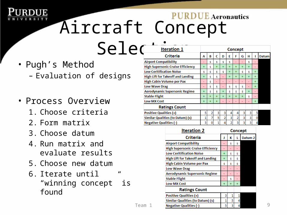
Aircraft Concept Selection• Pugh’s Method
– Evaluation of designs
• Process Overview1. Choose criteria2. Form matrix3. Choose datum4. Run matrix and evaluate
results5. Choose new datum6. Iterate until “winning
concept” is found9Team 1
Aircraft Concept Selection
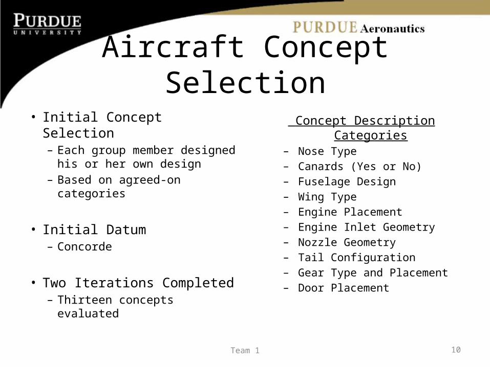
• Initial Concept Selection– Each group member
designed his or her own design
– Based on agreed-on categories
• Initial Datum– Concorde
• Two Iterations Completed– Thirteen concepts evaluated
Concept Description Categories– Nose Type– Canards (Yes or No)– Fuselage Design– Wing Type– Engine Placement– Engine Inlet Geometry– Nozzle Geometry– Tail Configuration– Gear Type and Placement– Door Placement
10Team 1

Initial Concept Designs
11Team 1

Team 1 12
Initial Concept Designs

Aircraft Arrangement
13Team 1
Team 1 14
System Definition Review
• Mission Objectives• Design Requirements• Aircraft Concept Selection• Advanced Technologies and Concepts• Initial Cabin Layout• Constraint Analysis and Diagrams• Sizing Studies• Summary of Aircraft Concept

Advanced Technologies/Concepts
• Components– Engine selection– Inlets– Combustors– Nozzles– Wing tips
• Other Technologies– Skin and structural
materials– Compression lift
15Team 1

Engine Selection
• Supersonic Regime Considerations– Operation power– Limit on pressure ratio– Engine noise– Combustion emissions
16Team 1

Engine Selection• Medium Bypass Turbofans
– Variable cycle technology• Superior efficiencies
– Higher TSFC– Reduced turbine
temperatures
Image: "Aircraft Design: A Conceptual Approach" - Daniel Raymer 17Team 1

Image: "Engine Design and Challenges for the High Mach Transport" ~ Koff
Combustor Technology• Nox Emissions
– Direct functions of Gas temperature
• Cannot remain above 3300° F for too long
• Unacceptable levels of Nox
• Efficient Mixing– Increase full vaporization
prior to injection

Inlet Design• Ramp Inlet• Variable Inlet Geometry
– Mass flow requirements– Shock creation and
control
Image: "Aircraft Design: A Conceptual Approach" - Daniel Raymer 19Team 1

Inlet Design Analysis
• Drag Trends– 2-D Ramp vs. Axisymmetric– Increase in drag
Image: "Aircraft Design: A Conceptual Approach" - Daniel Raymer
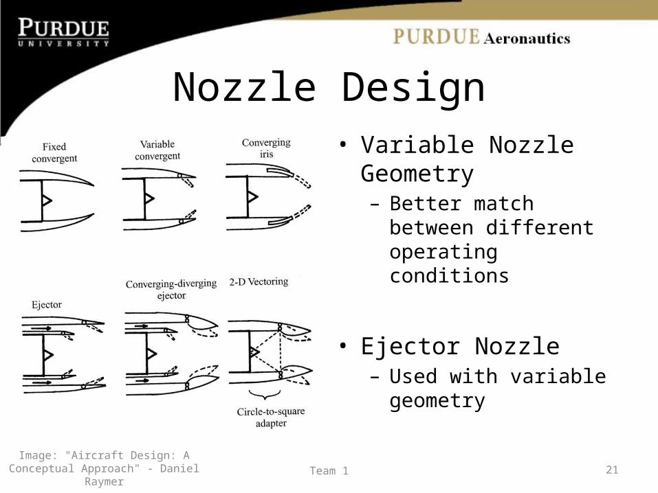
Nozzle Design• Variable Nozzle Geometry
– Better match between different operating conditions
• Ejector Nozzle– Used with variable geometry
Image: "Aircraft Design: A Conceptual Approach" - Daniel Raymer 21Team 1

Wing Tip Inclusion• Advantages
– Reduction of the AR during cruise– More stability surfaces– Reflection of the oblique shock (extra compression)
• Disadvantages– Extra complexity– Extra weight– May interfere with landing constraints in case of
failure
22Team 1
Team 1 23
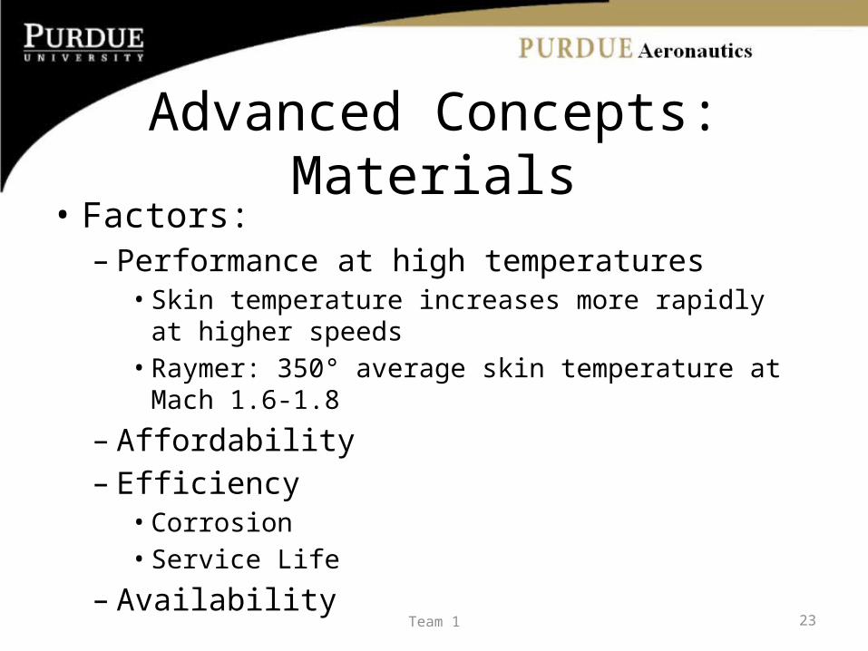
Advanced Concepts: Materials• Factors:
– Performance at high temperatures• Skin temperature increases more rapidly at higher
speeds• Raymer: 350° average skin temperature at Mach 1.6-1.8
– Affordability– Efficiency
• Corrosion• Service Life
– Availability

Team 1 24
Advanced Concepts: Materials• Aluminum Alloys
– Most widely used– Abundant– Moderate cost– Excellent strength-to-weight ratio– High strength: 7075– Aluminum Lithium Alloy comparable to composites– 250°F maximum operating temperature– Weak in fracture toughness and creep resistance

Team 1 25
Advanced Concepts: Materials• Titanium Alloys
– High stiffness– Resistant to high temperatures– Corrosion resistant – High strength to weight ratio– Difficult to form– Excessive weight– Expensive (5X aluminum)– Primary use on wing and tail leading edge– Also, engine components and landing gear

Team 1 26
Advanced Concepts: Materials• Composites
– Weight reduction– Filament-reinforced: high strength to weight ratio
and weight savings– Graphite Epoxy (Carbon-fiber composite): high
strength-to-weight ratio but very expensive (20X aluminum)
– Max temp: 350°

Team 1 27
Advanced Concepts: Materials• Composites:
– Cannot accept concentrated loads– Strength affected by many factors– Susceptible to damage– Internal damage difficult to find– Difficult to repair– Complex material properties

Team 1 28
Advanced Concepts: Materials• Aerion:
– Wing: Carbon Epoxy • Leading edge: Coated with metal for erosion resistance
– Fuselage: Aluminum & Composites• QSST:
– No new “breakthrough” materials• XB-70
– Stainless steel– Sandwiched honeycomb– Titanium

Team 1 29
Advanced Concepts: Materials• Next Steps:
– 2020: vast advances in composites– Two main focus points:
• Weight & temperature
– Different materials in different locations– Work with sizing
• Determine maximum loads
– Look into joints & sealants

Team 1 30
System Definition Review
• Mission Objectives• Design Requirements• Aircraft Concept Selection• Advanced Technologies and Concepts• Initial Cabin Layout• Constraint Analysis and Diagrams• Sizing Studies• Summary of Aircraft Concept

Initial Cabin Layout
31Team 1

Initial Cabin Layout
32Team 1
Initial Cabin Layout
33Team 1
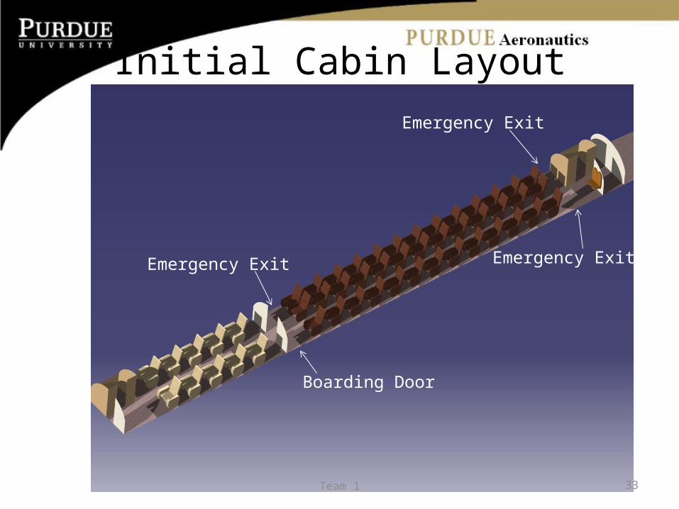
Boarding Door
Emergency Exit
Emergency Exit
Emergency Exit

Initial Cabin Layout•First Class Seat Pitch = 46”•Business Class Seat Pitch = 42”•1 Boarding Door (1R)•3 Emergency Exits•2 Lavatories
34Team 1

Initial Fuselage Dimensions
• Length = 196’• Width at Max = 9’• Width at Tail = 4’
35Team 1

Team 1 36
System Definition Review
• Mission Objectives• Design Requirements• Aircraft Concept Selection• Advanced Technologies and Concepts• Initial Cabin Layout• Constraint Analysis and Diagrams• Sizing Studies• Summary of Aircraft Concept

• Major Performance Constraints:-Cruise
• 1g Steady Level Flight, M = 1.8 at h=50,000 ft • Assuming Standard Atmosphere Conditions
-Subsonic Maneuver• 2g turn at 250 knots at h = 10,000 ft• Assuming 92% of the take off weight
-Takeoff Ground Roll • 6000 ft at h = 0 ft• +15° Hot Day
-Landing Ground Roll • 4000 ft at h = 0 ft • +15° Hot Day
-Second Segment Climb Gradient • above h = 0 ft• +15° Hot Day
Constraint Analysis / Constraint Diagram
37Team 1

Basic assumptions made for each constraint
CruiseSubsonic
Maneuver Take Off 2nd segment climb Landing
Engine Lapse Rate (α) 42 % 82% 99 % 99 % 99 %25 % Reverse T
Weight fraction (Wi/Wo) 91 % 92 % 100 % 100 % 100 %
AR 1.9 2.6 2.6 2.6 2.6
Oswald Efficiency 82 %
LE angle 60o
CLmax 1.2 1.2 1.2
Cdo 0.018 0.018
CDW 0.022
Number of engines 3
Climb Gradient 2.7 %
Distance Constraint 6000ft 4000ft
38Team 1
80 90 100 110 120 130 1400
0.1
0.2
0.3
0.4
0.5
0.6
0.7
0.8
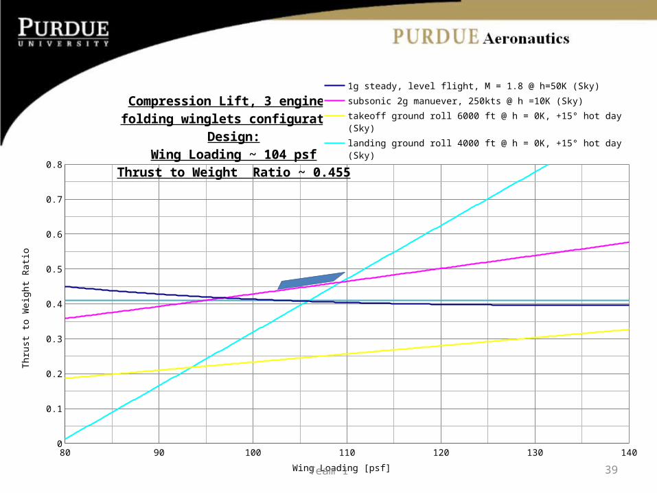
Compression Lift, 3 engines,folding winglets configuration
Design:Wing Loading ~ 104 psf
Thrust to Weight Ratio ~ 0.455
1g steady, level flight, M = 1.8 @ h=50K (Sky)
subsonic 2g manuever, 250kts @ h =10K (Sky)
takeoff ground roll 6000 ft @ h = 0K, +15° hot day (Sky)
landing ground roll 4000 ft @ h = 0K, +15° hot day (Sky)
second segment climb gradient above h = 0K, +15° hot day (Sky)
Wing Loading [psf]
Thr
ust
to W
eigh
t R
atio
39Team 1

80 90 100 110 120 130 1400
0.1
0.2
0.3
0.4
0.5
0.6
0.7
0.8
Cruise Subsonic Maneuver
Take Off Landing
2nd Segment Climb Linear (2nd Segment Climb)
Wing Loading [psf]
Thru
st to
Wei
ght R
atio
Compression Lift, 3 engines,Non-folding winglets configuration
Design:Wing Loading ~ 104 psf
Thrust to Weight Ratio ~ 0.515
40Team 1

Team 1 41
System Definition Review
• Mission Objectives• Design Requirements• Aircraft Concept Selection• Advanced Technologies and Concepts• Initial Cabin Layout• Constraint Analysis and Diagrams• Sizing Studies• Summary of Aircraft Concept

Current Sizing Approach
• Writing MATLAB code– Advances the Initial Sizing Spreadsheet
• More detailed breakdown of each segment of design mission to get more accurate segment weights, fuel weights
• More detailed geometry• Inclusion of Lift, Drag, SFC as functions of geometry,
engine specs, altitude, Mach number, etc.
42Team 1

InputsTSL/W0, W0/S, W0,guess, SFCSL
… etc
Determine Other VariablesTSL = (TSL/W0)W0
S = W0/(W0/S)*b AR S
We = f(W0, S, TSL, etc)
Wfuel = f(W0, S, TSL, etc)
W0,new = Wpay + Wcrew + We + Wfuel
W0,new ≈ W0,guess
W0,guess = W0,new
False
TrueW0
Main Code
43Team 1

InputsVcruise, Rcruise, Wcurrent
Di = f(geometry, Wi, M, h)SFC = f(h,M,D)
Li = Wi
CalculationsWi+1/Wi = exp[-(Rseg*C)/(V(Li/Di))
Wi+1 = Wi*Wi+1/Wi
Wcurrent = W1
i = 1:n
Wn+1
Example of segment function: Cruise
44Team 1
Component Weight Prediction
• Used component weight prediction equations from Raymer 15.3
• Used Concorde as “standard”– Obtained values for variables
• Calculated correction factor from Concorde– Published We / Predicted We
– Factor = 2.04• Will be used once more of our variables are
found/calculated45Team 1

Current Values
• Based on Initial Sizing Spreadsheet– ARcruise = 1.9
– T/W0 = 0.45
– W0/S = 107– SFC = 0.78 1/hr
• Gross T.O. Weight: 299,100 lbs• Fuel Weight: 169,300 lbs• Total Empty Weight: 118,200 lbs
46Team 1
Next Steps
• Include Engine Specs• Find reasonable prediction for wave drag• Employ advanced flight control equations for
better prediction of aerodynamic coefficients• Develop Lift, Drag, SFC, etc. functions • Finish Advanced Sizing Code
47Team 1

Team 1 48
System Definition Review
• Mission Objectives• Design Requirements• Aircraft Concept Selection• Advanced Technologies and Concepts• Initial Cabin Layout• Constraint Analysis and Diagrams• Sizing Studies• Summary of Aircraft Concept
Team 1 49
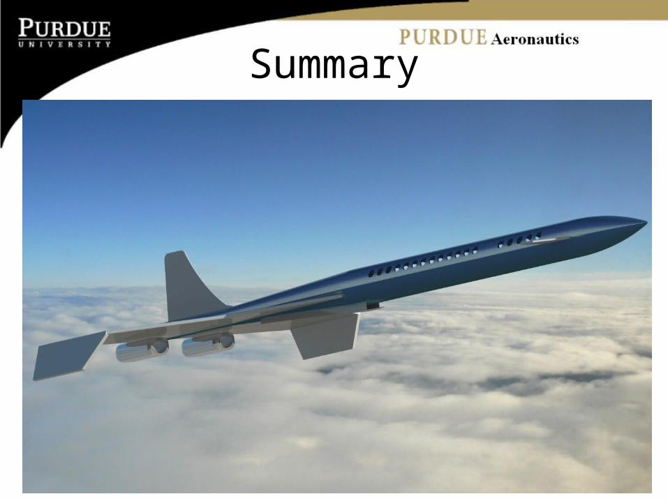
Summary

Team 1 50
SummaryRequirements Compliance Matrix
Requirement Unit Condition Target Threshold Design (to Date)
Takeoff Field Length [ft] < 10,000 11,800 11000
Range [nmi] > 5410 4000 5410
Payload [pax] > 49 35 49
Cruise Mach # [N/A] > 1.8 1.6 1.8
Cruise Efficiency [lb fuel/pax-nmi] < 0.25 0.33 0.36
Certification Noise [PldB] < 50 70 69
Cabin Volume per Pax [ft^3/pax] > 10 8 8.55
Cruise Altitude [ft] 50000 60000 50000
Aircraft Life [years] > 30 20 28
Aspect Ratio [N/A] < 2.6 1.9 1.9
Thrust to Weight Ratio [N/A] > 0.37 0.3 0.45
Wing Loading [N/A] > 125 95 104
Crew [crew] < 3 5 4
Table #. Requirements Compliance Matrix to Date

Team 1 51
Summary• Pugh’s method was used to evaluate design concepts• Engine concept evaluation led to the positive utilization
for variable cycle technology• Variable geometry for engine inlets and nozzles will
allow for most efficiency in supersonic regime• Material focuses are weight and temperature; different
materials will be used in different locations• Constraint diagrams show that limiting factor is subsonic
2g maneuver and landing• From trade studies, it was found that 3 engines were
preferred as well as folding winglets configuration• Excel sizing code updated and advanced sizing code in
progress

Team 1 52
Next Steps
• Third phase of sizing– Utilization of sizing code– Find more accurate weights
• Further investigation of advanced technologies• Create more accurate CATIA model• Structural and Dynamic Analysis
– Vertical tail sizing – Canard sizing
• Create Carpet Plots

References• Kauser, Fazal B., California State Polytechnic Univ., Pomona
AIAA-1994-2828 . ASME, SAE, and ASEE, Joint Propulsion Conference and Exhibit, 30th, Indianapolis, IN, June 27-29, 1994
• Bernard Koff, TurboVIsion, Inc., Miami, FL; Steven Koff, TurboVIsion, Inc., Miami, FL AIAA-2007-5344 . 43rd AIAA/ASME/SAE/ASEE Joint Propulsion Conference and Exhibit, Cincinnati, OH, July 8-11, 2007
• EVELYN, G. B., Boeing Commercial Airplane Co., Seattle, Wash.; JOHNSON, P. E., Boeing Commercial Airplane Co., Seattle, Wash.; SIGALLA, A., Boeing Commercial Airplane Co., Seattle, Wash. AIAA-1978-1051. American Institute of Aeronautics and Astronautics and Society of Automotive Engineers, Joint Propulsion Conference, 14th, Las Vegas, Nev., July 25-27, 1978, AIAA 14 p.
• Martin Sippel, DLR, German Aerospace Research Center, Cologne AIAA-2006-7976. 14th AIAA/AHI Space Planes and Hypersonic Systems and Technologies Conference, Canberra, Australia, Nov. 6-9, 2006
• Timothy Conners, Gulfstream Aerospace Corporation, Savannah, GA; Donald Howe, Gulfstream Aerospace Corporation, Savannah, GA AIAA-2006-30. 44th AIAA Aerospace Sciences Meeting and Exhibit, Reno, Nevada, Jan. 9-12, 2006
• Raymer, D. P., Aircraft Design – A Conceptual Approach, Third Edition, AIAA, Washington, DC, 1999, p. 1-14.
53Team 1

Team 1 54
• Seating Charts (Pitch and Width for Business and First on all airlines)http://www.seatguru.com/charts/business_class.php
• Airport database (runway lengths, codes, locations...)http://www.world-airport-codes.com/
• Market Sizehttp://travel.nytimes.com/2007/07/24/business/24premium.html
• Seat Pitchhttp://www.aerospaceweb.org/question/planes/seating/seat-pitch.jpg
• NASA Dryden fact sheet for Tu-144http://www.nasa.gov/centers/dryden/news/FactSheets/FS-062-DFRC.html
• Aerion Corp-Aerion datahttp://www.aerioncorp.com/technology
• USAF XB-70 Factsheet• F-14D data http://www.globalsecurity.org/military/systems/aircraft/f-14-specs.htm
M.A.T.Shttp://www.anft.net/f-14/f14-specification.htm
References

Back Up Slide
1g steady, level flight, M = 1.8 @ h=50K (Sky)
subsonic 2g manuever, 250kts @ h =10K (Sky)
takeoff ground roll 6000 ft @ h = 0K, +15° hot day (Sky)
landing ground roll 4000 ft @ h = 0K, +15° hot day (Sky)
second segment climb gradient above h = 0K, +15°
hot day (Sky)r 0.000362sl/ft^3 r 0.001756sl/ft^3 rho 0.00226sl/ft^3 rho 0.00226sl/ft^3 rho 0.00226sl/ft^3a 0.42 0.1523a 0.85 alpha 0.99 alpha 0.99 alpha 0.99b 0.91 b 0.92 beta 1 alpha_rev 0.25 beta 1
M 1.8 V 422ft/sCL max TO 1.2 beta 1
CL max TO 1.2
V 1742.4ft/s CD0 0.018 g 32.17ft/s^2CL max land 1.2 g 32.17ft/s^2
CD0 0.018 e 0.82 s_to 6000ft g 32.17ft/s^2 N 3AR 1.9 AR 2.6 mu 0.3 CGR 2.7%K 0.40996 q 156.3578lb/ft^2 s_l 4000ft CD0 0.018E_WD 1.8 n 2 AR 2.6LLE 40deg dh/dt 0ft/s e_TO 0.65d_max 9ft g 32.17ft/s^2 D CD0 0.0033l 180ft dV/dt 0ft/s^2CDW 0.002004 W0/Sq 549.5084lb/ft^2 79.1637414n 1dh/dt 1.666667ft/sg 32.17ft/s^2dV/dt 0ft/s^2
55Team 1


