8
Bushings PORIP Transformer Bushings with Porcelain Insulator 24 -170 kV Type RTKF

Bushings
PORIPTr a n s f o rmer Bushingswith Porcelain Insulator
24-170 kV Type RTKF
Routine testing
Each bushing is routine tested before leaving thefactory. The tests, either according to IEC or IEEES t a n d a rd, include partial discharge, tanδ and capac-itance measurement, as well as power frequencyvoltage withstand test. The test tap is also tested.
RIP
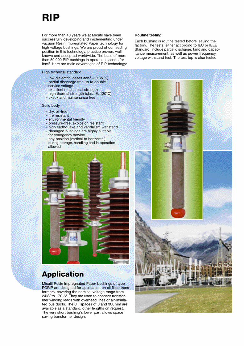
ApplicationMicafil Resin Impregnated Paper bushings of typePORIP are designed for application on oil filled trans-formers, covering the nominal voltage range from24kV to 170kV. They are used to connect transfor-mer winding leads with overhead lines or air-insula-ted bus ducts. The CT spaces of 0 and 300mm areavailable as a standard, other lengths on request.The very short bushing’s lower part allows spacesaving transformer design.
For more than 40 years we at Micafil have been successfully developing and implementing undervacuum Resin Impregnated Paper technology forhigh voltage bushings. We are proud of our leadingposition in this technology, practice proven, wellknown and accepted worldwide. The base of morethan 50.000 RIP bushings in operation speaks foritself. Here are main advantages of RIP technology:
High technical standard
- low dielectric losses (t anδ < 0,35 %)- partial discharge free up to double
service voltage- excellent mechanical strength- high thermal strength (class E, 120°C)- ckeck and maintenance free
Solid body
- dry, oil-free - fire resistant - environmental friendly - pressure-free, explosion resistant - high earthquake and vandalism withstand - damaged bushings are highly suitable
for emergency service - any position (vertical to horizontal)
during storage, handling and in operation a l l o w e d

Design
Flange, Head and Outdoor InsulatorAfter fixing the aluminium flange onto the body,the porcelain insulator and the aluminium head areassembled. The space between the RIP body andthe insulator is filled with the special, compressibledry filler MICAGEL. Such bushing is completely dry, allowing installation in any position, down tohorizontal. There is no need for oil level gauge.
Outdoor porcelain insulator has alternating shedsand a specific creepage distance of 31mm/k V. The brown colour is standard .
All bushings have on the flange two M12 holes forhandling and/or eart h i n g .
Conductor and TerminalsFor current lower than 1000A draw lead applicationis selected. The copper cable bolt is shown in Fig. 7.The cable bolt is fixed to the bushing’s head and canbe connected to the transformer leads by brazing orsoldering. This bolt acts as the bushing’s top term i n a l ,enabling the perfect connection between leads ando v e rhead line. On the top of each cable bolt there is ad e a e r a t ion scre w.
For current higher than 1000A removable copperconductor could be used. This type of bushing is notshown in this brochure, please contact Micafil formore information.
All bushings are equipped with electrical shield onthe bottom side. See Fig. 5 and 6. The aluminiumshield is epoxy resin insulated.
AccessoriesTest Tap
Each bushing is equipped with a standard test tap.The test tap is connected to the outmost aluminiumlayer and is automatically earthed, Fig. 9. Each testtap is tested with 3kV, 50Hz, for 1 minute.
For a testing purpose the cap must be unscrewed and female-female pin adapter used. Such anadapter is available from Micafil.
RIP – Active Part
The main insulation of the bushing is a dry, solid,Resin Impregnated Paper – RIP insulation, withaluminium foils inserted. In order to optimise theelectrical field in axial and radial direction, the size,exact position and number of foils are computer calculated. The paper body is vacuum dried, impreg-nated with epoxy resin and cured. This process wasdeveloped by Micafil 40 years ago and constantly
improved, having todaythe most advanced pro-cess. The result is a highquality insulation system.High mechanical strength,low tanδ and partial dis-charge free bushings upto double service voltageare only some of the mainadvantages PORIP bus-hings have. The RIP bodyis oil and gas tight.
kV kV kV kV kV kV kV kV mm mm
24 14 50 125 25 16 60/50 150 255 745
36 21 70 170 34.5 22 80/75 200 345 1120
52 30 95 250 46 29 105/95 250 450 1615
72.5 42 140 325 69 44 160/140 350 670 2250
100 58 185 450 – – – – 825 3100
123 71 230 550 92 73 185/155 450 1050 3815
145 84 275 650 138 88 310/275 650 1200 4495
170 98 325 750 161 102 365/315 750 1440 5270
Type RT K F
RTKF 24-150/1000 T
RTKF 36-200/1000 T
RTKF 52-250/1000 T
RTKF 72.5-350/1000 T
RTKF 100-450/800 T
RTKF 123-550/800 T
RTKF 145-650/800 T
RTKF 170-750/800 T
mm kg 185 240 300 400
0 22 710 850 940 1040
300 25 650 800 860 950
0 24 680 800 900 1025
300 27 630 730 820 920
0 26 675 765 850 1010
300 29 615 700 780 900
0 46 645 735 820 1000
300 49 590 670 750 890
0 72 590 675 740 880
300 75 530 630 675 805
0 85 590 675 740 880
300 88 530 630 675 805
0 104 540 645 720 860
300 110 495 590 660 800
0 180 535 630 715 850
300 195 490 570 655 800
I E C IEEE / ANSI C u rrent (A)
165Ø
100Ø
max.200Ø
92Ø
testtap
sealingarea
max. 330Ø
6 holesØ 16
max.200Ø
130Ø230Ø
testtap
119Øsealingarea
max. 355Ø
8 holesØ 16
max.250Ø
270Ø
134Ø
170Ø
testtap
sealingarea
max. 390Ø
12 holesØ 16
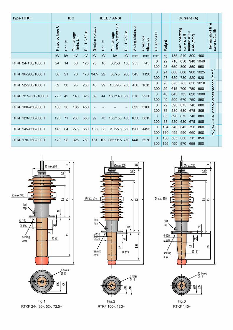
Fig.1RTKF 24-, 36-, 52-, 72.5-
Fig.2RTKF 100-, 123-
Fig.3RTKF 145-

Technical Dataa n dD i m e n s i o n s
Fig. L L16
1 665 120
1 965 420
1 780 140
1 1080 440
1 900 140
1 1200 440
1 1165 175
1 1465 475
2 1370 230
2 1670 530
2 1680 310
2 1980 610
3 1910 360
3 2210 660
4 2215 420
4 2515 720
Dimensions (mm)
L2 L4 L5
405 230 95
500 325 95
620 450 95
850 675 100
1000 840 100
1230 1070 105
1380 1220 105
1625 1465 105
L6
0
300
0
300
0
300
0
300
0
300
0
300
0
300
0
300
L6 Fig.
5
5
5
5
5
5
6
6
RTKF 24-150/1000 T
RTKF 36-200/1000 T
RTKF 52-250/1000 T
RTKF 72.5-350/1000 T
RTKF 100-450/800 T
RTKF 123-550/800 T
RTKF 145-650/800 T
RTKF 170-750/800 T
Type RT K F
testtap
sealingarea
max. 405
270Ø170Ø
159Ø
max.250Ø
12 holesØ 16
40Ø
65Ø
109Ø
40Ø
75Ø
134Ø
Fig.4RTKF 170-
Fig.5Electrical shieldfor 24 - 123kV
Fig.6Electrical shield
for 145 and 170kV
Fig.7cable bolt

Recommendation forBushings Installation
Distance from bushing’s lower part to the eart h e dp a rts depends on the shape of surrounding parts, as well as on quality and condition of the transform e roil. The recommended minimum distances (A) to beused under standard conditions are shown in Fig. 8.
Checking andMaintenance
One of the main advantages of dry PORIP bushings is that they are fully check/m a i n t e n a n c e - f ree. If there is any problem on the transformer or in the network, the condition of the bushing can be checkedby measuring tanδ and capacitance of the bushing’sactive part, using the test tap.
A
Typ Up (kV) A (mm)
RTKF 24-, 36-, 52- 50-105 80140 90160 100
RTKF 100- 185 115185 115230 145275 170310 200325 210365 230
Fig. 9Test tap
Our concept - your benefit
Fig. 8
RTKF 72.5-
RTKF 123-
RTKF 145-
RTKF 170-

Other Micafil Bushings
The example of nomenclature used to designate our PORIP bushings:
R T K F 123 - 550 / 800 T
Dry filling, MICAGEL
Rated current (A)
Lightning impulse voltage 1,2/50µs (kV)
Rated voltage (kV)
R = RIP bushingT = Transformer applicationK = kurz (in German = short lower part)F = Freiluft (in German = outdoor)
Besides the PORIP bushings described here, Micafil manu-factures other transformer bushings, a wide range of bushings for SF6 insulated switch-gears, walls, apparatus, as well as fullycustomer-tailored bushings. Here our scope of supply:
Transformer bushings with nominal voltage up to 550 kV:
• Oil-Air bushings24 - 550kV up to 5’000A
• Oil-Air high current bushings17,5 - 52kV up to 40’000A
• Oil - SF6 bushings52 - 765kV up to 4’000A
• Oil - Oil bushings24 - 550kV up to 3’150A
We are also specialists for explosion-proof GIS bushings:
• SF6 - Air bushings 52 - 550kV up to 4’000A
The possibility to install RIP bushings in any position gives themunique advantage as wall bushings:
• 24 - 362kV up to 4’000A
Mechanical strength and oil-free-solution make RIP technologyideal for railway bushings:
• 12 - 52kV up to 2’000A
If you have another wish and you need a special solution,come to us - we have the bushing for you.
Type Designation

Micafil Ltd.Badenerstrasse 780CH – 8048 ZurichSwitzerlandPhone +41.1.435 63 33Fax +41.1.435 64 44E-mail [email protected]
or visit our homepage: www.micafil.ch
We have done our best ...
All information in this document is subject to changewithout notice and does not represent a commitmenton the part of Micafil Ltd.
... and we will do our best.
It‘s your choice.
For more information contact us


