111
0279\CC10111612_TOC PORT WASHINGTON WATER POLLUTION CONTROL DISTRICT STANDARD SPECIFICATIONS AND DETAILS D&B ENGINEERS AND ARCHITECTS, P.C. November 2016
0279\CC10111612_TOC
PORT WASHINGTON WATER POLLUTION CONTROL DISTRICT
STANDARD SPECIFICATIONS AND DETAILS
D&B ENGINEERS AND ARCHITECTS, P.C. November 2016

0279\CC10111612_TOC i
PORT WASHINGTON WATER POLLUTION CONTROL DISTRICT
STANDARD SPECIFICATIONS AND DETAILS
TABLE OF CONTENTS
SPECIFICATION SECTIONS
02200 Earthwork .................................................................................................02200-1 thru 18
02430 Manholes ..................................................................................................02430-1 thru 12
02440 Thermoplastic Sewer Pipe .......................................................................02440-1 thru 15
02441 House Connections, Risers and Cleanout Assemblies .............................02241-1 thru 6
02450 Ductile Iron Sewer Pipe ...........................................................................02450-1 thru 15
03200 Reinforcing Steel .....................................................................................03200-1 thru 4
03251 Construction Joints...................................................................................03251-1 thru 3
03300 Cast-in-Place Concrete.............................................................................03300-1 thru 26
DETAIL DRAWINGS
Drawing No. 1 – 4’-0” Diameter Precast Manhole
Drawing No. 2 – 5’-0” Diameter Precast Manhole
Drawing No. 3 – Precast Manhole Top/Transition Slab – Typical Rebar Arrangement
Drawing No. 4 – Manhole Cover and Steps
Drawing No. 5 – Typical House Connection without Riser
Drawing No. 6 – Wye Branch Assemblies for House Connections
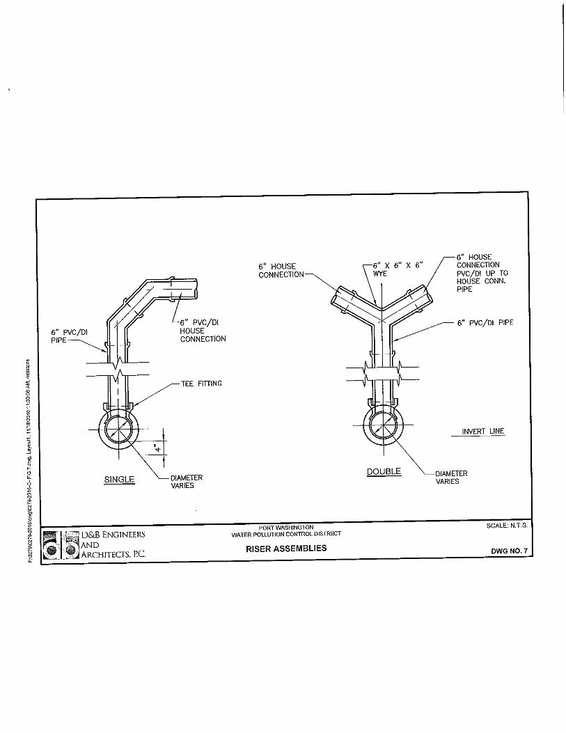
Drawing No. 7 – Riser Assemblies

0279\02200_CC10101601 PWWPCD General Spec.
November 2016
02200-1
SECTION 02200
EARTHWORK
PART 1 - GENERAL
1.1 Description
A. Scope:
1. Under this Section, the Contractor shall make all
necessary excavations for pits, piping and
structures and for all required or ordered purposes
incidental to the work; shall backfill such
excavations to the extent necessary; shall dispose
of all excess materials and shall do miscellaneous
grading.
2. Earthwork required under other Contracts (if
applicable), if any, shall be included under that
Contract and shall conform to all applicable
requirements of Section 02200.
3. All such work shall be done as indicated on the
Drawings and as herein specified at no additional
cost to the Owner; except as/if specifically covered
in other sections.
4. Excavation shall include the removal, storage,
segregation, handling, rehandling, refill and
disposal of any and all materials of whatever nature
encountered in the work and shall include all
dewatering and sheeting and bracing.
5. Only the use of light excavating machinery will be
permitted, except in places where operation of same
will cause damage to adjacent property, utilities,
structures or completed work, in which case hand
methods shall be employed.
6. The program of excavation, sheeting and bracing
shall be carried out in such a manner as to prevent
undermining or disturbing the foundations of
existing structures or of work previously completed
under this contract.

0279\02200_CC10101601 PWWPCD General Spec.
November 2016
02200-2
7. All excavation shall be made in the dry.
1.2 Submittals
A. Samples:
1. At least two weeks prior to the date of anticipated
use, the Contractor shall submit, to the Engineer,
for approval, a representative sample of all on-site
and off-site material required along with a
laboratory sieve analysis of each sample. The
Contractor shall notify the Engineer in writing of
the source of each sample.
B. Disposal Sites:
1. List of disposal sites for unsuitable materials and
all required permits for use of the sites.
C. Manufacturer’s Data:
1. Submit for approval manufacturer’s specifications,
performance characteristics and operating
instructions for the compaction equipment.
1.3 Accessibility
A. The Contractor shall maintain the site in such condition
that all the employees of the Owner may conduct their
work without interference.
1.4 Lines of Excavation
A. All excavations shall be made in such manner and to such
widths as will give ample room for properly building and
inspecting the structures and piping they are to contain,
for such sheeting and bracing, as may be necessary, and
for application of damp-proofing if required.
B. When excavating for structural work, special care shall
be taken not to disturb the bottom of the excavation and
the final removal of material to subgrade shall not be
made until just before concrete is placed.
0279\02200_CC10101601 PWWPCD General Spec.
November 2016
02200-3
1.5 Quality Assurance
A. Permits and Regulations: Contractor shall perform
excavation work in compliance with applicable
requirements of governing authorities having
jurisdiction.
B. Design Criteria:
1. All steel work for sheeting, shoring, bracing and
other related Work shall be in accordance with the
provisions of the AISC "Specifications for the
Design, Fabrication and Erection of Structural Steel
for Buildings", except that field welding will be
permitted.
2. Contractor shall be wholly responsible for
installing and operating the system used to
accomplish the sheeting and bracing if shown or
otherwise required.
C. Reference Standards: Comply with applicable provisions
and recommendations of the following except as otherwise
shown or specified.
1. ASTM A 328, Steel Sheet Piling.
2. ASTM D 422, Particle-Size Analysis of Soils.
3. ASTM D 698, Moisture-Density Relations of Soils,
using 5.5 lb (2.5 kg) Rammer and 12-inch (304.8 mm)
Drop.
4. ASTM D 1556, Density of Soil in Place by the
Sand-Cone Method.
D. Tests:
1. The Contractor shall retain the services of a testing
laboratory approved by the Engineer to make tests
and determine acceptability of the fill or material
as listed below.
2. Required Tests:
a. Select Fill Samples: Gradation, ASTM D 422.

0279\02200_CC10101601 PWWPCD General Spec.
November 2016
02200-4
b. Compacted Select Fill: Compaction, ASTM D 698
and ASTM D 1556.
3. Testing laboratory will submit copies of the
following reports directly to Engineer with a copy
to Contractor:
a. Tests on borrow material.
b. Field density tests.
E. Locating Underground Utilities:
1. The Contractor shall obtain utility markouts on all
public and private properties in accordance with all
local and state requirements where work is to be
performed. Prior to any excavation or construction,
the Contractor shall notify the Owner, all utility
companies and applicable agencies and request a
markout of their lines and properties in the field
in the area of the proposed work.
2. Prior to any excavation, in addition to utility
location and markouts performed by the local and
state required services, the Contractor shall
accurately locate existing utilities by excavating
test pits as directed by the Engineer. The
Contractor shall backfill/restore the holes and
pits, and mark out the existing utilities and take
extreme caution against damaging the utilities
during excavation or sheeting installation.
3. During construction / excavation, the contractor
shall locate each utility by hand digging methods
prior to the use of mechanical excavation equipment.
During construction / excavation, if the contractor
encounters evidence of suspected unmarked utilities,
such as magnetic tape or other underground markers,
the contractor shall promptly determine the location
of the suspected utility, if any, before proceeding
with the work. The contractor shall cooperate with
the Owner and the utility companies involved to avoid
delay or interference of service normally performed
by their lines and properties.
4. The Contractor shall take extreme caution against
damaging utilities when excavating, sheeting and

0279\02200_CC10101601 PWWPCD General Spec.
November 2016
02200-5
backfilling, during construction of test probes and
test pits and while performing the work required
under this Contract.
1.6 Protection of Persons and Property
A. Barricade open excavations occurring as part of this Work
and post with warning lights. Contractor shall provide
“Jersey” type concrete barriers with reflective tape
where shown on the contract drawings or required by OSHA,
or the agency having jurisdiction. Operate warning lights
during hours from dusk to dawn each day and as otherwise
required.
B. Protect structures, utilities, sidewalks, pavements, and
other facilities from damage caused by settlement,
lateral movement, undermining, washout and other hazards
created by contractor's operations.
C. Consult Engineer and obtain his approval before removing,
trimming, or disturbing trees, shrubs, plants, fences,
rails, walks, structures or other facilities that are
encountered on the line of the excavation.
D. Structures, utilities, sidewalks, pavements and other
facilities removed or disturbed shall be replaced to their
original condition, unless otherwise shown, specified or
directed.
E. Dust Control: Contractor shall conduct all of his
operations and maintain the area of his activities,
including sweeping and sprinkling of roadways, so as to
minimize creation and dispersion of dust. In addition,
Contractor shall be responsible for controlling dust
caused by his operation of vehicles and equipment,
clearing or for any reason whatever.
F. Odor Control: As an odor abatement measure, cover, at the
end of each work day, all areas of organic or odorous
material which were exposed during excavation with a
minimum 6-in and a maximum 24-in deep of clean fill.
Excavated organic or odorous material shall be
immediately removed off-site and shall not be stockpiled
on-site.
G. Roadways and Walks: Unless otherwise approved by
Engineer, excavated material and materials of
0279\02200_CC10101601 PWWPCD General Spec.
November 2016
02200-6
construction shall be so deposited, and the Work shall be
so conducted, as to leave open and free for pedestrian
traffic all crosswalks, and for vehicular traffic a
roadway not less than 10 feet in width. All hydrants,
valves, and other facilities which may require access
during construction shall be kept accessible for use.
During the progress of the Work, Contractor shall maintain
such crosswalks, sidewalks, and roadways in satisfactory
condition and the Work shall at all times be so conducted
as to cause a minimum of inconvenience. Temporary
bituminous macadam (2-inch minimum) shall be installed at
all disturbed sidewalk areas until such time as the final
restoration is performed.
PART 2 - PRODUCTS
2.1 Segregation of Excavated Materials
A. General:
1. All materials removed by excavation shall be
stockpiled and tested for gradation and compaction
(relative density), by the Contractor for the
presence of any unsuitable materials (e.g.,
organics, silts or clays) or unsuitable materials
(e.g., debris from prior construction).
2. Locations of these stockpiles shall be subject to
the approval of the Engineer. The stockpiles shall
be segregated by approved use (i.e., Topsoil, Select
Fill, General Fill), and shaped to drain.
3. Unsuitable material shall be immediately removed
from the Owner’s property and the project site and
disposed of by the Contractor in an acceptable
disposal site. Contractor shall furnish appropriate
manifests for disposal, to the Engineer.
4. Selection of material for each classification shall
be at the direction of the Engineer.
5. Surplus excavated material, either unsatisfactory
for or over and above that required for backfilling
or regrading shall be disposed of by the Contractor,
at his own expense, off the site of the work.

0279\02200_CC10101601 PWWPCD General Spec.
November 2016
02200-7
6. All materials removed by excavation (excluding
paving, concrete, etc.) shall be reused as General
or Select Fill, unless found to be unsuitable or
unusable.
7. Local, deeper excavations should be made, as
required for construction.
8. Local dewatering should be made, as required for
construction.
9. Field density tests for all backfill material shall
be performed at the rate of 1 test per 150 cu yds
placed, one test per lift, or 1 test per structure,
whichever results in the greater number of tests.
Compaction criteria shall be as defined below.
10. Compaction criteria for stockpiled material reused
in construction shall be based upon tests made on
materials taken from stockpile.
11. Compaction criteria shall be the highest dry unit
weight and corresponding moisture content, as
determined by the following tests:
Location ASTM-D1557 or ASTM-D4253/4
Below structures and
pipe
98% 85%
All other areas 95% 80%
B. Select Fill:
1. Where quantity of on-site fill material is not
sufficient, additional select fill shall be provided
by the Contractor as ordered by the Engineer and
shall meet the following requirements:
Sieve Size Percent Passing
1” 100
#4 60-95
#20 35-85
#60 10-30
#100 5-15
#200 less than 4
0279\02200_CC10101601 PWWPCD General Spec.
November 2016
02200-8
2. Materials for select fill shall consist of well
drained on-site or off-site material, free of clay,
mud, frost, organic matter or construction debris.
3. Select Fill shall be used to backfill around pipe
(except as otherwise specified) and under
structures, and as shown on the Plans or directed
by the Engineer.
4. Unless otherwise specified, directed by the Engineer
or shown on the Plans, Select Fill shall be placed
in compacted lifts of 6” maximum thickness and
compacted by means of a mechanical tamper to at
least 98% dry density (ASTM-D1557) or 85%
(ASTM-D4253/4). The use of heavy duty self-
propelled compaction equipment/compaction equipment
excavator attachments is prohibited. Compaction
shall be accomplished by utilizing “Walk Behind”
vibratory plate or jumping jack hammers. A minimum
of 3’ backfill cover is required prior to use of
“Walk Behind” jumping jack hammers.
5. All controlled backfilling shall be performed with
Select Fill obtained either from excavated material
or from outside sources.
C. General Fill:
1. Material for General Fill shall be acceptable for
backfill in areas other than under structures and
piping as shown or directed.
2. The selection of material for General Fill and the
location for its use shall be as shown on the plans
and as directed by the Engineer.
3. It shall consist of clean, compactible sound
granular material free from rubbish or other
unsuitable material.
4. Unless otherwise specified, directed by the Engineer
or shown on the plans, general fill shall be placed
in compacted lifts of 12” maximum thickness and
compacted by means of a mechanical tamper to at
least 95% dry density (ASTM-D1557) or 80%
(ASTM-D4253/4). The use of heavy duty self-
propelled compaction equipment/compaction equipment

0279\02200_CC10101601 PWWPCD General Spec.
November 2016
02200-9
excavator attachments is prohibited. Compaction
shall be accomplished by utilizing “Walk Behind”
vibratory plate or jumping jack hammers. A minimum
of 3’ backfill cover is required prior to use of
“Walk Behind” jumping jack hammers.
D. Flowable Fill
1. Flowable fill shall be utilized as a backfill
material when ordered by the Engineer and conform
to New York State DOT Standard Specification 733-01
Flowable Fill for Controlled Low Strength Material
(CLSM).
2. The CLSM mix design shall be developed to ensure
that the flowable fill is excavatable through the
entire service life of the installation. Mixture
ingredients and proportions shall be submitted for
approval. The flowable fill mixture shall be
designed as a low strength, flowable material
requiring no subsequent vibration or tamping to
achieve consolidation. CLSM shall have a 28-day
unconfined compressive strength between 40 psi and
150 psi, excavatability by hand tools and
conventional machinery such as backhoes.
3. The flowable fill shall be provided by an approved
ready-mix concrete supplier and shall be produced,
transported and delivered through conventional
ready-mix equipment. Certified test results of
unconfined compressive strength of the mix design
shall be submitted for review and approval by the
Engineer prior to delivery/use.
4. The utilization of the flowable fill material shall
be in strict accordance with the manufacturer's
recommendations and as approved by the Engineer.
E. Unsuitable Material:
1. Material unsuitable for use in backfilling are clay,
boulders, peat, construction debris, organics and
any other material so designated by the Engineer.
2. Stockpiling of Unsuitable Material shall not be
permitted.

0279\02200_CC10101601 PWWPCD General Spec.
November 2016
02200-10
3. Unsuitable Material must be promptly removed from
the site and disposed of by the Contractor, at his
own expense, off the site of the work.
F. Excess Material:
1. Any excavated material not required for use in the
project shall become the property of the Contractor
and shall be removed by him from the site.
G. Crushed Stone: Crushed rock conforming to the following
gradation:
Sieve Size Percent Passing
2”
1 1/2” 0-10
1” 30-65
3/4” 85-100
3/8” 95-100
2.2 Filter Fabric
A. The fabric used shall conform to the Specifications for
Mirafi 140-N.S. Fabric as manufactured by Celanese Fiber
Marketing Company, or an approved equal. The fabric
shall be non-woven nylon/polypropylene fabric having the
following properties:
1. Minimum Weight 140 g/m2
2. Average Thickness 30 mils
3. Grab Strength, Wet Retention
70 degrees F.
120 lbs
100%
4. Grab Elongation, Wet Retention
at 70 degrees F.
130%
40%
5. Trapezoid Tear Strength 65 lbs.
6. Air Permeability 250 cfm/ft2
2.3 Sheeting and Bracing
A. The Contractor shall be required to use sheeting and
bracing (temporary support system) on this project, where

0279\02200_CC10101601 PWWPCD General Spec.
November 2016
02200-11
conditions or laws require it. All costs for sheeting
shall be included in the lump sum price bid. The temporary
support system shall be designed by a licensed
professional engineer (NYS) engaged by the Contractor.
B. The Contractor shall furnish, put in place, and maintain
such sheeting, bracing, etc., as may be necessary to
prevent groundwater from penetrating into the excavation
and to support the sides of the excavation to prevent any
movement of earth which could in any way diminish the
width of the excavation to less than that necessary for
proper construction, or could otherwise injure or delay
the work, or endanger adjacent structures, or
embankments. All sheeting shall be adequate and conform
to the provisions of the current New York State Industrial
Code Rule 23 as established by the New York State
Department of Labor, Board of Standards and Appeals, as
well as all appropriate State and Federal regulations
including OSHA.
C. The Contractor shall leave in place any sheeting,
bracing, etc., which the Engineer may direct him in
writing to leave in place, at any time during the progress
of the work, for the purpose of preventing injury to
structures or property.
D. The Engineer may direct that timber used for sheeting and
bracing be cut off at any specified elevation.
E. All sheeting and bracing not to be left in place shall
be carefully removed in such manner as not to endanger
the construction or other structures. All voids left or
caused by the withdrawal of sheeting shall be backfilled
immediately with select fill and compacted by ramming
with tools especially adapted to the purpose, by
watering, or by other means as may be directed.
F. Vibrating type hammers shall not be permitted. Any
material which stops the installation of sheeting shall
be removed by the Contractor.
G. Wood Sheeting: New or used timber meeting the
requirements for Douglas Fir Dense Construction grade or
Southern Pine No. 2 Dense S3.

0279\02200_CC10101601 PWWPCD General Spec.
November 2016
02200-12
H. Steel Sheeting: Steel conforming to ASTM A328. Steel for
soldier piles, wales and braces may be new or used and
shall conform to ASTM A36.
I. Safe and satisfactory installation of the sheeting shall
be the entire responsibility of the Contractor.
2.4 Removal of Water
A. The Contractor’s attention is directed to the fact that
some of the work may be below groundwater, perched water,
etc. Therefore, the need for an adequate and well planned
dewatering system may be necessary to allow excavation
and construction to be performed in a dry suitable
environment.
B. The Contractor, at all times during construction, shall
provide and maintain ample means and suitable equipment,
consistent with conditions encountered, with which to
promptly remove and properly dispose of all water
entering excavations or other parts of the work. All
excavations shall be kept dry at all times until the
structures to be built or pipelines to be installed
therein are completed and backfilled to approximate final
grades except where otherwise approved by the Engineer
in writing. Concrete for structures, pipe and sanitary
structures shall be placed on subgrades which are dry.
Water shall be disposed of in a suitable manner so as to
avoid damage to adjacent property, existing structures
and all work under construction. It shall be the
Contractor’s responsibility to prevent flotation of any
structures during construction.
C. Systems used to lower the groundwater level shall be
maintained in operation continuously, 24 hours a day,
7 days a week, until the structures are completed
adequately to prevent flotation. Termination of the
dewatering operation shall receive approval of the
Engineer.
D. No additional compensation will be given to the
Contractor because of damage from flooding caused by
groundwater or surface waters rising above ground
elevations.
E. The Contractor shall be responsible for obtaining and
adhering to all provisions of necessary dewatering
0279\02200_CC10101601 PWWPCD General Spec.
November 2016
02200-13
permits at no additional costs to the Owner. Groundwater
shall not be permitted to be discharged into storm drains
or surface waters without proper approval from regulatory
agencies.
F. Dewatering system shall be installed as required to lower
the groundwater level in general excavation at least
2 feet below final subgrade.
G. Prior to installing and operating any dewatering system,
the Contractor shall install a series of observation
wells and monitor same for a minimum period of two working
days in order to determine the groundwater level at the
time of construction. The observation wells shall be
located both within and adjacent to the proposed
construction site. Observation wells located within the
limits of the proposed construction site shall be
situated outside of the physical limits of the structures
and protected from damage. Any damaged observation wells
shall be replaced or repaired. During construction, the
water level in the observation wells shall be measured
and recorded periodically. During start-up, the water
levels shall be read a minimum of once each day and
reported to the Engineer. After start-up, the water
levels shall be read a minimum of once each week.
2.5 Unauthorized Excavation
A. Whenever the excavation is carried beyond or below the
lines and grades shown on the plans, or given by the
Engineer, the Contractor shall at his own expense, refill
such excavated space with select fill as directed by the
Engineer.
PART 3 - EXECUTION
3.1 Protection of Existing Facilities
A. The Contractor shall protect all existing facilities,
utilities, etc. which are to remain in service from damage
due to his operations throughout the duration of the
work. Facilities which are to be replaced during the
course of the Contract shall be protected until the
Engineer gives notice that they are no longer required
to be in service.
0279\02200_CC10101601 PWWPCD General Spec.
November 2016
02200-14
B. Facilities which must be protected include but are not
limited to utilities, adjacent structures/houses,
building, tanks, piping, manholes, valves, etc. Prior to
execution of the work, the Contractor shall check and
verify governing dimensions and elevations. The
Contractor and Engineer shall jointly survey the
condition of adjoining structures. Photographs and
records shall be made of any prior settlement or cracking
of structures, pavements, and the like, that may become
the subject of possible damage claims.
C. The Contractor shall not use machinery which threatens
the integrity of existing facilities or facilities under
construction. When the machinery in use threatens the
integrity of such facilities, the Contractor shall use
other machinery or do the work by hand. Any damage
resulting from improper equipment use shall be repaired
at the expense of the Contractor.
D. The Contractor shall immediately repair or replace any
facilities which are damaged by his operations. Repairs
or replacement, etc. shall be made to current standards
of the Owner.
E. All existing electric conduits, lighting poles, telephone
lines, chains, fences or other structures especially
including underground process piping which are
encountered or uncovered by the excavation and which do
not, in the opinion of the Engineer, require to be changed
in location, shall be carefully supported and protected
from injury by the Contractor and if damaged or removed,
they shall be restored by the Contractor, without
compensation, to at least as good condition as that in
which they were found immediately before work was begun.
3.2 Excavation
A. Pipeline Excavation:
1. Pipe trenches shall be excavated below the pipe
bottom by an amount sufficient for placement of the
pipe bedding shown on the drawings and as specified.
2. Trench width shall be minimized to greatest extent
practical but shall conform to the following:

0279\02200_CC10101601 PWWPCD General Spec.
November 2016
02200-15
a. Sufficient to provide room for installing,
jointing and inspecting piping, but in no case
wider at top of pipe than pipe barrel outside
diameter plus 2 feet (5 foot wide maximum).
b. Enlargements at pipe joints may be made if
required and approved by Engineer.
c. Sufficient for sheeting, bracing and sloping.
d. Sufficient to allow thorough compacting of
granular embedment adjacent to bottom half of
pipe.
e. Do not use excavating equipment which requires
the trench to be excavated to excessive width.
3. At road crossings, trenching width shall be
minimized by the use of sheeting, trench boxes or
similar protection methods.
B. Structure Excavation:
1. Excavation shall be made to the grades shown on the
Contract Drawings and to such widths as will give
suitable room for construction of the
structures/manholes, for bracing and supporting,
pumping and draining. The bottom of the excavations
shall be rendered firm and dry and in all respects
acceptable to the Owner.
2. Excavation shall be accomplished by methods which
preserve the undisturbed state of subgrade soils.
For structures having multiple bearing levels or
adjacent structures at different levels, excavation
and foundation construction shall first be
accomplished at the lowest levels to prevent
undermining foundations and disturbing adjacent
bearing soils at higher levels.
3. Excavation equipment shall be satisfactory for
carrying out the work in accordance with the
Specifications. Earth shall not be plowed, scraped,
or dug with machines so near to the finished subgrade
as to result in excavation of, or disturbance of
material below grade.
0279\02200_CC10101601 PWWPCD General Spec.
November 2016
02200-16
4. When excavation for foundations has reached final
depths, the Engineer shall be notified and will
inspect conditions. If materials and conditions are
not satisfactory to the Engineer, the Engineer will
issue instructions as to the procedures for
correction of the unsatisfactory condition.
5. During final excavation to subgrade level, take
precautions required to prevent disturbance of
material. Hand excavate the final 6-in as necessary
to obtain a satisfactory undisturbed bottom.
3.3 Preparation of Subgrades
A. Subgrade for Reinforced Concrete Structures:
1. Provide a minimum of 12 inches of crushed stone below
the bottom slab of structures and manholes.
B. Subgrade for Pipe:
1. Undisturbed subgrade and 6 inches of crushed stone
acceptable to the Engineer.
C. Unsuitable Subgrade:
1. When clay or other material incapable of supporting
the loads to be imposed is encountered at or near
the subgrade elevation of any pipe or structure, the
Contractor shall remove such material and replace it
with Select Fill unless otherwise directed.
3.4 Controlled Backfilling
A. Backfill under structures, pipes, sidewalks and roads
shall be performed with Select Fill either from
stockpiled material or from outside sources.
B. Should the excavated material not be suitable or if more
select fill is required than excavated, select fill shall
be brought in from outside sources. Payment shall be
included in the lump sum price as bid.
C. Filling against the walls of structures shall be done as
ordered and particular care shall be taken to prevent
damage to green masonry by falling, rolling or sliding
material.

0279\02200_CC10101601 PWWPCD General Spec.
November 2016
02200-17
D. Fill shall not be placed against walls until they have
attained sufficient strength to safely resist the thrust
of the material.
E. Backfill shall be placed in horizontal layers and
compacted as indicated elsewhere in this specification.
F. Backfilling shall not be made during freezing weather.
It shall not be made with frozen material or when
materials already placed are frozen.
G. If any of the backfilling shall settle so as to be below
the required levels for the proposed finished surface at
any place before the final acceptance of the work to be
done under this Contract, the Contractor shall, bearing
expense and cost, supply additional materials and build
up the low places as directed.
H. A testing laboratory approved by the Engineer, shall be
employed by the Contractor to perform all density tests
and sieve analysis to certify the specified compaction
and quality of material. Costs of tests shall be borne
by the Contractor. If the tests indicate unsatisfactory
compaction, the Contractor shall provide the additional
compaction necessary to obtain the specified degree of
compaction. All additional compaction work shall be
performed by the Contractor at no additional cost to the
Owner until the specified compaction is obtained. This
work shall include complete removal of unacceptable fill
areas and replacement and recompaction until acceptable
fill is provided, as determined by the Engineer.
3.5 Grading
A. Areas to be graded shall be constructed true to grade,
shall be shaped to drain, and shall be maintained free
from extraneous accumulations until final inspection has
been completed and the work has been accepted.
B. Finished grade elevations shall be as shown on the
Contract Drawings and as directed by the Engineer.
C. Pavement, gutters, curbs, walks, driveways and roadways
disturbed or damaged by the Contractor’s operation shall
be restored or replaced by him as specified or as shown

0279\02200_CC10101601 PWWPCD General Spec.
November 2016
02200-18
on the contract drawings or to original or better
condition.
+ + END OF SECTION + +

0279\02430_CC10111601 PWWPCD General Spec.
November 2016
02430-1
SECTION 02430
MANHOLES
PART 1 - GENERAL
1.1 Description
A. Scope: Contractor shall furnish all labor, materials,
equipment and incidentals necessary to provide all
manholes shown, specified and otherwise required to
complete the Work.
B. General:
1. Structures shall conform in shape, size, dimensions,
material, and other respects to the details shown
the District Standard Details Drawings.
2. Pipe penetrations, inverts, shall conform to the
details shown on the District Standard Details
Drawings. Side inverts shall be curved and main
inverts, where direction changes, shall be laid out
in smooth curves of the longest possible radius which
is tangent to the centerlines of adjoining
pipelines.
C. Related Work Specified Elsewhere:
1. Section 02200, Earthwork.
2. Section 03200, Reinforcing Steel.
3. Section 03300, Cast-In-Place Concrete.
1.2 Quality Assurance
A. General:
1. The Contractor must give the Engineer twenty-four
hours written notice plus travel time prior to the
commencement of any manufacturing process or testing
sequence for manhole components made of precast
concrete.

0279\02430_CC10111601 PWWPCD General Spec.
November 2016
02430-2
2. At the place of manufacture of precast concrete
components, the Engineer reserves the right at all
times:
a. To inspect the materials, the processes of
manufacture, and the records of analysis and
tests.
b. To select test specimens.
c. To inspect and test manhole components,
accessories and joint material.
d. To inspect and test cast-in-place concrete.
3. Upon delivery to the site the Engineer reserves the
right to inspect and test:
a. Manhole components, accessories and joint
material.
b. Cast-in-place concrete.
4. All manhole components made of precast concrete
delivered to the site shall be clearly marked at the
factory with the date of manufacture and the
manufacturer’s identification. Omission of this
information may be cause for rejection of the manhole
components.
B. Reference Standards: Comply with applicable provisions
and recommendations of the following, except as otherwise
shown or specified.
1. ASTM C 32, Sewer and Manhole Brick (made from Clay
or Shale).
2. ASTM C 139, Concrete Masonry Units for Construction
of Catch Basins and Manholes.
3. ASTM C 140, Sampling and Testing Concrete Masonry
Units.
4. ASTM C 207, Hydrated Lime for Masonry Purposes.
5. ASTM C 478, Precast Reinforced Concrete Manhole
Sections.
0279\02430_CC10111601 PWWPCD General Spec.
November 2016
02430-3
6. ASTM C 923, Resilient Connectors Between Reinforced
Concrete Manhole Structures and Pipes.
7. ASTM D 543, Test for Resistance of Plastics to
Chemical Reagents.
8. ASTM D 1248, Specification for Polyethylene Plastics
Molding and Extrusion Materials.
C. Manufacturer’s Testing:
1. Tests on reinforced concrete manhole components
shall be in accordance with the “Physical
Requirements” section of ASTM C 478.
2. The Contractor shall ensure that the manufacturer
furnishing manholes under these Specifications shall
be fully equipped with testing facilities of the
approved type and capacity. The Contractor shall
furnish the required number of specimens of manhole
components at no additional cost to the Owner.
3. Absorption Test:
a. For every 100 manhole bases and manhole riser
sections manufactured, one specimen shall be
selected for an absorption test. As a minimum,
one specimen representing a manhole base and
manhole riser section shall be tested. The
absorption test shall be performed in
accordance with the requirements of ASTM C 478.
b. In the event any specimen fails to meet any of
the requirements of the absorption test, then
two additional test specimens shall be selected
for each specimen that failed, from the lot
represented by the specimen that failed. The
additional specimens shall be tested; and
should any one of these fail to meet the
requirements specified, the entire lot
represented by these tests shall be rejected.
4. Compression Test:
a. For each of the four manhole components made of
precast and cast-in-place concrete (manhole

0279\02430_CC10111601 PWWPCD General Spec.
November 2016
02430-4
base, manhole riser section, transition slab
and top slab) compression tests shall be made
on standard rodded concrete cylinders. A
minimum of four concrete cylinders shall be
molded for each day’s production of a
particular manhole component. Each cylinder
representing a particular manhole component
shall be molded from the same concrete batch
utilized for the manufacture of the component.
The concrete cylinders shall be tested in
accordance with the specifications of ASTM C
478 except for the required strengths of the
cylinders, which shall be as follows:
The strength of precast concrete shall be
considered satisfactory if both of the
following requirements are met:
1) The average at 28 days of three
consecutive strength tests equals or
exceeds 4000 psi.
2) No individual strength test falls below
required strength by more than five
hundred psi.
b. In the event a concrete cylinder’s compressive
strength is unsatisfactory the manufacturer
shall select one of the following two options:
1) The entire day’s production of the manhole
component represented by the test cylinder
shall be rejected.
2) The manufacturer shall have the option to
drill two cores from manhole components
represented by the unsatisfactory test
cylinder and perform compression tests on
the cores. The manhole component sampled
shall be selected by the Engineer. Should
the compression tests on these core
samples meet the strength requirements as
specified in this Section, the Engineer
shall determine the acceptability of all
manhole components represented by the
test, considering the results of the tests
on the concrete cylinders as well. Based

0279\02430_CC10111601 PWWPCD General Spec.
November 2016
02430-5
on the Engineer’s evaluation, if the
compression test for the cores is
determined to be unacceptable the entire
day’s production of the manhole component
represented by the core sample shall be
rejected. The Engineer’s decision shall
be considered final.
5. Top and Transition Slabs:
a. In lieu of a proof of design test for the top
and transition slabs the Contractor shall
submit in the Shop Drawings top slab and
transition slab design calculations and
Drawings for approval by the Engineer.
b. The design calculations shall be in accordance
with requirements specified in this Section.
1.3 Submittals
A. Submit for approval samples of brick and all accessories
required for the manholes.
B. For all manholes submit Shop Drawings for approval. Shop
Drawings shall include, but not be limited to, the
following information:
1. Size and spacing of steel reinforcement.
2. Wall and slab thicknesses.
3. Concrete cover over steel reinforcement.
4. Joint design between component manhole sections,
show all dimensions.
5. Concrete mix design including design compressive
strength.
6. Design of flexible manhole seal assemblies and/or
specified seal arrangement
7. Final grade elevation at manhole.
8. All pipe penetrations into manhole.

0279\02430_CC10111601 PWWPCD General Spec.
November 2016
02430-6
9. Plan of manhole base invert.
10. Certificates of compliance with referenced
standards.
11. Certified test results.
1.4 Product Delivery, Storage and Handling
A. Manhole components shall not be shipped until the 28 day
strength is reached.
B. Handle all manhole components carefully with approved
handling devices. Manhole components shall be kept
completely free from dirt and foreign matter.
C. Manhole components with damaged “O” ring or sealing
grooves will not be approved.
D. Contractor shall clearly mark and immediately remove all
damaged manhole components.
E. Certified copies of all test results shall accompany each
manhole component shipment and shall be furnished to the
ENGINEER with each shipment.
PART 2 - PRODUCTS
2.1 General
A. Manholes shall conform to the details shown. All concrete
manhole bases, transition slabs, riser sections and top
slabs shall be precast, unless otherwise approved.
B. Except where otherwise specified manhole components shall
conform to ASTM C 478.
C. Mark date of manufacture and name or trademark of
manufacturer on all precast concrete items.
D. Unless shown otherwise on the Drawings, joints for all
precast concrete manhole components shall be of the bell
and spigot type with a round “O” ring rubber gasket
meeting the requirement of ASTM C443, or a preformed
plastic sealing compound as specified in the Federal

0279\02430_CC10111601 PWWPCD General Spec.
November 2016
02430-7
Specifications SS-S-210A. Joints shall be formed so that
adjacent manhole sections will fit and seal properly.
E. All lifting holes shall be sealed tight with a solid
rubber plug driven into the holes and the remaining void
filled with 1 to 2 cement-sand mortar.
2.2 Castings
A. General: All manhole frames and covers (standard and
oversize) unless otherwise shown or required, shall be
locking type and watertight. All manhole frames shall be
of the nonadjustable type, with frames suitable for
installation over manholes. Refer to Standard Details
Drawings.
1. Material: Cast iron conforming to ASTM A48,
Class 30.
2. Size: As shown on the Standard Details Drawings
suitable for slab type penetrations or manholes as
required and specified.
3. Construction: All manhole castings shall be heavy
duty watertight nonadjustable consisting of frame
and cover. Bearing surfaces between frame and cover
shall be machined, fitted together, and match marked
to prevent rocking. Gasket shall be 1/4” min.
neoprene. All manhole castings for slab type
penetrations shall be Campbell Foundry 6500 Series
nonadjustable consisting of frame and cover. Manhole
castings for nonslab type installations shall be
1500 series. All castings shall include a security
saddle plate for padlocking. Casting cover shall
include the Owners Name, as directed by the Engineer.
Refer to Standard Details Drawings.
4. Product and Manufacturer: Manhole frames and covers
shall be as manufactured by:
a. Campbell Foundry.
b. Neenah.
c. LeBaron Foundry Company.
d. Or equal.

0279\02430_CC10111601 PWWPCD General Spec.
November 2016
02430-8
B. Terminal or Flush Manholes: Manhole covers equipped with
vent holes shall be installed on all terminal or flush
type manholes (not applicable).
C. Oversize Manhole Frame and Cover: Oversized manhole
frames and covers, as shown on the Drawings, shall be
furnished and installed on all manholes.
D. Provide stainless steel manhole cover inserts for each
manhole cover provided. The insert shall be constructed
of 16 gauge 304 stainless steel and designed to allow a
loose fit into the casting for easy removal. It shall
include a gasket, lift handle and relief valve. The
insert shall be custom made to fit the manhole frame. The
gasket shall be made of closed cell neoprene and shall
have a pressure-sensitive adhesive on one side. The
gasket shall have a minimum total thickness of 1/8-inch.
The gasket is to be installed by the manufacturer. The
insert shall have a heavy duty handle made of plastic
coated 304 stainless steel cable installed in the bottom
of the insert. The handle shall be attached with 304
stainless steel bolts with flat washers and self-locking
nuts. The gas relief valve shall be designed to release
at a pressure of 0.5 to 1.5 psi and have a water leak
down rate no greater than 5 gallons per 24 hours.
2.3 Concrete
A. Concrete shall conform to the requirements of Section
03300, Cast-In-Place Concrete.
2.4 Brick Masonry
A. Brick: All brick used as specified under this Section
shall meet the requirements stated in ASTM C32.
B. Mortar and Plaster: All mortar and plaster required to
complete brick masonry as shown on the Drawings or as
specified herein shall be in conformance with ASTM C150
Type II.
2.5 Steel Reinforcement
A. Steel reinforcement shall be placed in all concrete
manhole components as shown on the Drawings and as
specified herein. The reinforcing shown on the Drawings

0279\02430_CC10111601 PWWPCD General Spec.
November 2016
02430-9
is the minimum amount required. All steel reinforcement
shall meet the requirements specified in Section 03200,
Reinforcing Steel.
2.6 Top Slabs and Transition Slabs
A. Each top slab placed on the top of the manhole riser
sections shall be manufactured in accordance with the
Standard Details Drawings and as specified herein.
B. Concrete slab thicknesses shall not be less than the
dimensions shown on the Drawings.
C. Each top slab and transition slab shall be of acceptable
design and of sufficient strength to safely support an
AASHTO H-20 loading.
2.7 Manhole Bases and Manhole Riser Sections
A. The minimum diameter or size for each manhole base shall
be as shown on the Standard Details Drawings.
B. Manhole base sections minimum slab and wall thicknesses
shall be as shown on the Standard Details Drawings.
C. Manhole base sections slotted to fit over existing sewer
pipes shall be installed on cast-in-place base slab as
shown on Standard Details Drawings.
D. Manhole bases shall be cast monolithically to at least 12
inches above the top of the highest pipe entering the
manhole.
E. Manhole riser sections shall have a minimum wall thickness
of 6 inches and the same internal diameter as the manhole
base (unless otherwise shown).
F. Manhole riser sections shall be constructed of various
lengths to provide the correct height with the fewest
joints. No pipe penetrations shall be located at a joint.
2.8 Pipe Connections
A. Each manhole base shall be provided with circular or
slotted openings at the required locations and elevations
for the proper connection of all pipes. The circular pipe
connections shall be sealed with a flexible modular seal

0279\02430_CC10111601 PWWPCD General Spec.
November 2016
02430-10
assembly; slotted openings shall be sealed with nonshrink
grout.
B. The flexible manhole seal assembly shall be installed in
accordance with the recommendations of the seal assembly
manufacturer and shall conform to ASTM C923. Flexible
modular seal assemblies shall permit at lease a seven
degree deflection from the centerline of the opening in
any direction while maintaining a watertight connection.
The flexible modular seal assembly shall be manufactured
by:
1. Kor-N-Seal (Trelleborg Pipe Seals/NPC)
2. Or equal.
C. When a nonshrink grout is used to seal the pipe
connection, the concrete bonding agent and nonshrink
grout used to seal the pipe connections in the slotted
manhole base section openings shall be in accordance with
Section 03300.
D. The existing pipe within the slotted manhole base shall
be saw cut and removed as shown on the Drawings after
grouting the pipe penetrations into the manhole base
section.
PART 3 - EXECUTION
3.1 Preparation
A. Excavation: All excavation required for the construction
of manholes shall be performed as specified in Section
02200, Earthwork.
B. Shoring: Shoring of all excavations shall be provided as
specified in Section 02200, Earthwork.
C. Dewatering: Dewatering shall be performed as specified.
3.2 Installation
A. No manhole components shall be installed prior to the
acceptance of all test results by the Engineer.
0279\02430_CC10111601 PWWPCD General Spec.
November 2016
02430-11
B. Manhole Bases, Base slab for slotted manhole Base Section:
During excavation the soil below each base shall not be
disturbed. Over-excavated areas shall be backfilled with
crushed stone and compacted as specified in Section 02200,
Earthwork. Manhole bases and base slab shall be checked
for proper bearing on the subgrade and proper elevation.
Orientation of manhole bases shall be set to receive the
incoming and outgoing pipes at the designated elevations.
Special care shall be taken in placing concrete supports
around the bottom of the pipes in manhole bases to obtain
a waterproof structure.
C. Manhole Riser Sections:
1. Set sections vertical with sections in true
alignment.
2. Install sections, joints and gaskets in accordance
with manufacturers recommendations.
D. Joints:
1. Joints between manhole components shall be made with
the materials specified in Paragraph 2.1.D. of this
Section.
2. Gaps between sections shall not exceed 3/8-inch.
E. Manhole Watertightness: All manholes shall be free of
visible leakage. Exfiltration/infiltration testing shall
be performed for each manhole installed as specified with
the pipe testing. Each manhole shall be periodically
inspected for leaks, and all leaks shall be repaired in
a manner subject to the Engineer’s approval.
F. Brick Masonry:
1. Brick masonry may be utilized to close up openings
in manhole walls where existing pipes have been
removed during construction. Installation of bricked
up openings shall not interrupt maintenance of
sewage flow.
2. Brick shall be satisfactorily wet when being laid
and each brick shall be laid in mortar so as to form
full bed, end and side joints in one operation. The
joints shall not be wider than 3/8-inch.

0279\02430_CC10111601 PWWPCD General Spec.
November 2016
02430-12
3. Following the placement of the brickwork, a one half
inch layer of cement mortar shall be applied to the
exterior surface of the brick and troweled to a
smooth finish.
G. Covers for Manholes: Installation shall be as shown on
the Contract Standard Details Drawings.
+ + END OF SECTION + +

0279\02440_CC10111602 PWWPCD General Spec.
November 2016
02440-1
SECTION 02440
THERMOPLASTIC SEWER PIPE
PART 1 - GENERAL
1.1 Description
A. Scope:
1. Contractor shall furnish all labor, materials,
equipment and incidentals as shown on the Contract
Drawings, specified and required to provide PVC
sewer pipe, fittings and specials necessary to
complete the Work.
2. Work shall include but not be limited to: the
excavation for the sewer trench including the
removal of masonry and boulders; the stockpiling of
all suitable excavated material; the disposal of
all excess materials; bracing, sheeting and
dewatering, the furnishing and laying of the pipe
and house connection tees or wyes; the removal and
disposal of existing pipe; the backfilling of the
sewer pipe trenches; tests for leakage and
deflection; the location and protection of
utilities and structures; protection, removal and
reinstallation of fences and landscaping; and all
other work required for the complete installation
of the sewers subject to acceptance, exclusive of
the work specified under separate items.
3. Concrete cradle shall be required under all pipe
coupling and adapters.
B. Related Work Specified Elsewhere:
1. Section 02200, Earthwork.
1.2 Quality Assurance
A. Source Quality Control: Obtain pipe and fittings from
one manufacturer.
B. Reference Standards: Comply with applicable provisions
and recommendations of the following, except as
otherwise shown or specified.

0279\02440_CC10111602 PWWPCD General Spec.
November 2016
02440-2
1. ASTM D 1598, Test Method for Time-to-Failure of
Plastic Pipe Under Constant Internal Pressure.
2. ASTM D 1599, Test Method for Short-Time Hydraulic
Failure Pressure of Plastic Pipe, Tubing and
Fittings.
3. ASTM D 1784, Rigid Poly(Vinyl Chloride) PVC
Compounds and Chlorinated Poly(Vinyl Chloride) CPVC
Compounds.
4. ASTM D 1785, Poly(Vinyl Chloride) (PVC) Plastic
Pipe, Schedules 40, 80 and 120.
5. ASTM D 2122, Determining Dimensions of Thermoplastic
Pipe and Fittings.
6. ASTM D 2467, Socket-Type Poly(Vinyl Chloride) (PVC)
Plastic Pipe Fittings, Schedule 80.
7. ASTM D 2564, Solvent Cements for Poly(Vinyl
Chloride) (PVC) Plastic Pipe and Fittings.
8. ASTM D 2774, Underground Installation of
Thermoplastic Pressure Piping.
9. ASTM D 2846, Chlorinated Poly (Vinyl Chloride)
(CPVC) Plastic Hot- and Cold-Water Distribution
Systems.
10. ASTM F 437, Threaded Chlorinated Poly (Vinyl
Chloride) (CPVC) Plastic Pipe Fittings, Schedule 80.
11. ASTM F 439, Socket-Type Chlorinated Poly(Vinyl
Chloride) (CPVC) Plastic Pipe Fittings, Schedule 80.
12. ASTM F 441, Chlorinated Poly (Vinyl Chloride) (CPVC)
Plastic Pipe, Schedules 40 and 80.
13. ASTM F 493, Solvent Cements for Chlorinated Poly
(Vinyl Chloride) (CPVC) Plastic Pipe and Fittings.
14. Standard No. 14, National Sanitation Foundation.
15. American National Standards Institute.
16. ASTM D 3034, Sanitary Piping

0279\02440_CC10111602 PWWPCD General Spec.
November 2016
02440-3
17. ASTM F 477, Rubber Gaskets
1.3 SUBMITTALS
A. Shop Drawings: Submit for approval Shop Drawings showing
the following:
1. Catalog Data consisting of specifications,
illustrations and a parts schedule that identifies
the materials to be used for the various piping
components and accessories. The illustrations shall
be of sufficient detail to serve as a guide for
assembly and disassembly.
2. Complete layout and installation drawings with
clearly marked dimensions. Piece numbers which are
coordinated with the tabulated pipe layout schedule
shall be clearly marked. Scale and size of the
drawings shall conform to the specifications in the
General Conditions.
B. Tests: Submit description of proposed testing methods,
procedures and apparatus. Submit copies of all test
reports.
C. Certificates: Submit certificates of compliance with
referenced standards.
D. Record Drawings: Submit in accordance with the
requirements of the Specification.
1.4 PRODUCT DELIVERY, STORAGE AND HANDLING
A. Handle all pipe, fittings and accessories carefully with
approved handling devices. Do not drop or roll pipe off
trucks. Do not otherwise drop, roll or skid pipe.
Materials that are cracked, chipped, gouged, dented or
otherwise damaged will not be approved.
B. Store pipe and fittings on heavy wood blocking or
platforms so they are not in contact with the ground.
C. Pipe, fittings and specials shall be unloaded as close
to the place where they are to be laid as is practical,
at a location which has been approved by the Engineer.
Interiors shall be kept completely free from dirt and
foreign matter.
0279\02440_CC10111602 PWWPCD General Spec.
November 2016
02440-4
D. No material furnished under this specification shall be
shipped to the job site until all submittals have been
approved.
PART 2 - PRODUCTS
2.1 MATERIALS
A. General:
1. Joints shall be as specified. If not specified, use
push-on joint for buried piping.
2. Pipe Marking:
a. Class designation shall be cast or painted on
each piece of pipe and fitting.
b. Each piece of pipe and fitting shall be
clearly marked with a designation which shall
conform with designations shown on the Shop
Drawings.
B. PVC Gravity Sewer Pipe:
1. Polyvinyl chloride pipe shall conform to AWWA C900
specification FM 1612, 150 psi DR 18. PVC pipe
shall have a maximum stiffness of 364 psi at a
maximum 5% deflection.
2. The bell joint shall conform to ASTM D3139.
3. PVC fittings and couplings shall conform to the
requirements of the PVC pipe for classification and
size.
4. Rubber gaskets shall conform to ASTM F477 and
factory installed in the bell of the pipe, fittings
and couplings. The plain end of the pipe shall be
marked by the manufacturer to show the depth of the
penetration into the bell or coupling. Lubricant
shall be supplied by the manufacturer and conform
to ASTM D1785 cells class 12454.
5. PVC DR 18 pipe shall be Blue Brute as manufactured
by JM Eagle or equal.

0279\02440_CC10111602 PWWPCD General Spec.
November 2016
02440-5
C. Transitions from One Type of Pipe to Another:
1. Provide all necessary adapters, specials and
connection pieces required when connecting
different types and sizes of pipe or connecting
pipe made by different manufacturers.
2. Where new pipe is to be connected to existing pipe,
the existing pipe shall be cut straight and smooth.
The two pipes shall be joined with a flexible
neoprene boot with stainless steel compression
straps. This boot shall be manufactured by Fernco,
or approved equal. Contractor shall verify type,
size and class of existing sewer where replacement
pipe is being installed and order the appropriate
“Fernco Coupling” as necessary. Be advised that
standard style couplings will not be permitted to
be installed on sewers of different materials,
class or size.
D. Restraints, Supports and Thrust Blocks:
1. Provide concrete and metal cradles, collars,
kickers, and blocks as shown or otherwise required
and approved by Engineer.
2.2 Identification
A. All pipeline material shall be stamped, marked or
identified with the following:
1. Name of manufacturer.
2. Pipe size.
3. Pipe material.
4. Wall thickness.
5. Rating.

0279\02440_CC10111602 PWWPCD General Spec.
November 2016
02440-6
PART 3 - EXECUTION
3.1 Installation
A. General:
1. Install piping as shown on the Standard Details
Drawings, specified and as recommended by the
manufacturer.
2. Request instructions from Engineer before
proceeding if there is a conflict between the
manufacturer’s recommendations and the Standard
Details Drawings or Specifications.
3. Pipe, fittings and accessories that are cracked,
damaged or in poor condition will be rejected at
the time of laying, the pipe shall be examined
carefully for defects, and should any pipe be
discovered to be defective after being laid, it
shall be removed and replaced with sound pipe by
the Contractor at his expense.
4. For specially fabricated piping, the Contractor
shall provide the services of a competent
manufacturer’s installation specialist when pipe
installation begins, unless otherwise approved by
Engineer.
5. Conflicts between piping systems and equipment or
structures shall be presented to the Engineer for
determination of corrective measures before
proceeding.
6. Minimum cover over PVC piping shall be four feet
unless otherwise shown or approved by the Engineer.
7. Earthwork required is specified in Section 02200.
B. Piping:
1. Install straight runs true to line and elevation.
2. Provide temporary caps or plugs over all pipe
openings at the end of each days work and when
otherwise required or directed by Engineer.
0279\02440_CC10111602 PWWPCD General Spec.
November 2016
02440-7
3. Cutting: Cut pipe from measurements taken at site,
not from Drawings.
4. Bed pipe with materials as specified below and as
shown on the Contract Drawings.
a. Trenches shall be excavated below the pipe
bottom by an amount sufficient for the
placement of granular embedment material for
pipe bedding as shown on the drawings or as
specified. All loose and unsuitable material
shall be removed from the trench bottom.
b. Granular embedment material (select fill)
shall be placed in accordance with the
requirements of Section 02200, Earthwork,
within the following limits:
1) Six (6) inches below the bottom of the
pipe to six (6) inches above the crown of
the pipe for pipe sizes of 30 inch
diameter and smaller.
2) Twelve (12) inches below the bottom of
the pipe to twelve (12) inches above the
crown of the pipe for pipe sizes greater
than 30 inches in diameter.
c. Granular embedment (select fill) shall be
placed in maximum 6-inch layers and compacted
for the full width of the trench. Recesses in
the embedment shall be provided around each
joint to allow space for making joints and
inspection.
5. Carefully and thoroughly compact all pipe bedding
and fill.
6. No piping shall be laid until Engineer approves the
bedding condition.
7. No pipe shall be brought into position until the
preceding length has been bedded and secured in its
final position.
8. All trenches and excavation shall be backfilled to
the original surface of the ground or to such other
grades as may be shown or directed.
0279\02440_CC10111602 PWWPCD General Spec.
November 2016
02440-8
9. All backfilling shall be carried along as speedily
as possible. As soon as the mortar and masonry are
sufficiently set and required tests are completed,
backfill shall proceed immediately.
10. In all backfilling of trenches and around
structures, all loose lumber, braces, rubbish and
refuse shall be removed from the space to be
backfilled and no such materials will be permitted
in the backfill.
11. All backfilling, unless otherwise specified, shall
be done with sound material, free from waste,
objectionable organic matter, rubbish or other
unsuitable materials. In general, the Contractor
shall utilize all suitable excess material
available from the contract work for fill, where
required. No frozen material containing lumps over
6 inches in the largest dimensions shall be used
for backfilling. Only fine granular material shall
be used for backfilling to a depth of at least
2 feet above the top of the pipe. Unsuitable
material, as determined by the Engineer, shall be
replaced with select fill as ordered.
12. Backfill shall be solidly compacted by mechanical
tamping or other approved methods as the work
progresses. Where stones occur in backfill, they
shall be distributed throughout the mass so that
all interstices are solidly filled with fine
material.
13. The fine granular material required for backfilling
to a depth of at least 2 feet over the tops of sewer
pipes shall be of suitable quality, free from
stones, pieces of masonry and refuse, deposited on
all sides, wetted until moist and solidly tamped in
6-inch layers in such a manner as to avoid injuring
the piping or structures, or producing unequal
pressure thereon. Special attention shall be paid
to the compaction of backfill up to the spring line
of the pipe by hand or mechanical tampers.
14. Compacting of the backfill material shall be
mechanical tamping or other suitable methods.
Jetting will not be allowed. Compaction shall be
performed in maximum 6-inch lifts.
0279\02440_CC10111602 PWWPCD General Spec.
November 2016
02440-9
15. In backfilling around structures other than pipe,
the material used shall be granular in character,
and shall be compacted in a manner similar to that
used in compacting backfill in trenches.
16. All compaction procedures shall achieve a minimum
compaction density of 95% of Standard Proctor
Maximum Density. At minimum, one test shall be
taken per manhole location and one test per 50
lineal feet of pipe installed. The Contractor shall
employ a testing laboratory, approved by the
Engineer, to perform these tests. All costs shall
be borne by the Contractor.
17. When sheeting is withdrawn, all cavities in or
adjoining the trench shall be solidly filled and
compacted. Sheeting shall be withdrawn as backfill
operations are being performed. When sheeting is
left in place, all cavities behind the sheeting
shall be solidly filled and compacted.
18. The maximum size of broken stone or rock permitted
in the backfill will be 6 inches in diameter, except
where permitted by the Engineer. In no case may
stones rest against the pipe.
C. Laying Pipe:
1. Conform to manufacturer’s instructions and to AWWA
C600, AWWA M9, AWWA M11, AWWA M23 where applicable.
2. Install all pipe accurately to line and grade shown
unless otherwise approved by Engineer. Remove and
relay pipes that are not laid correctly.
3. Slope piping uniformly between elevations given.
4. Ensure that water level in trench is at least
12 inches below bottom of pipe. Do not lay pipe in
water. Maintain dry trench until jointing and
backfilling are complete.
5. Start laying pipe at lowest point and proceed
towards the higher elevations, unless otherwise
approved by Engineer.
6. Place bell and spigot pipe so that bells face
upstream unless otherwise approved by Engineer.
0279\02440_CC10111602 PWWPCD General Spec.
November 2016
02440-10
7. Excavate around joints in bedding and lay pipe so
that only the barrel receives bearing pressure from
the trench bottom.
8. Permissible deflections at joints shall not exceed
75 percent of the amount allowed by manufacturer.
9. Prior to laying pipe, every precaution shall be
taken to ensure that no foreign material enters the
piping.
10. All pipe and fittings shall be carefully examined
for cracks, damage or other defects while suspended
above the trench, before installation. Defective
materials shall be immediately removed from site.
11. Interior of all pipe and fittings shall be
inspected and all dirt, gravel, sand, debris or
other foreign material shall be completely removed
from pipe interior before it is moved into the
trench.
12. Field cutting pipe, where required, shall be made
with a machine specially designed for cutting
piping. Cuts shall be carefully done, without
damage to pipe or lining, so as to leave a smooth
end at right angles to the axis of pipe. Cut ends
shall be tapered and sharp edges filed off smooth.
Flame cutting will not be allowed.
13. Blocking under piping shall not be permitted unless
specifically accepted by Engineer for special
conditions.
14. Where connecting new pipe to existing manholes, the
demolition of existing manhole walls shall be done
in a neat, workmanlike manner, and limited in size
to the minimum necessary to remove the existing
pipe and install the new sewer pipe. Grout shall be
nonshrink type with 1/4-inch overlay of polyester
patching system such as Quick-Rok manufactured by
Fosroc, Sikadur Le Mod Gel Mortar 1:1 Gel/Sand
manufactured by Sika, or equal. After the new pipes
are in place and grouted, the molded concrete
invert fill shall then be replaced as required,
true to the sewer pipe invert elevations, and shall
be well shaped to smoothly channel the flow into
the outlet pipe. Bypassing shall be maintained
0279\02440_CC10111602 PWWPCD General Spec.
November 2016
02440-11
until the new concrete invert has cured, to the
satisfaction of the Engineer.
D. Joints:
1. General:
a. Make joints in accordance with the pipe
manufacturer’s recommendations and the
requirements below.
b. Cut piping accurately and squarely and install
without forcing or springing.
c. Ream out all pipes and tubing to full inside
diameter after cutting. Remove all sharp edges
on end cuts.
d. Remove all cuttings and foreign matter from
the inside of pipes and tubing before
installation. Thoroughly clean all pipe,
fittings, valves, specials, and accessories
before installing. Bell and spigot mating
surfaces shall be thoroughly wire brushed and
wiped clean and dry immediately before pipe is
installed.
2. Gaskets shall be suitable for service intended in
accordance with manufacturer’s ratings and
instructions.
3. Lubricate and adjust gaskets and “O” rings as
recommended by manufacturer.
4. After “O” rings are compressed and before pipe is
brought fully home, each gasket shall be carefully
checked for proper position around full
circumference of the joint.
3.2 Testing of Piping
A. General:
1. Test all piping as specified below unless otherwise
authorized by Engineer.
2. Notify Engineer 48 hours in advance of testing.

0279\02440_CC10111602 PWWPCD General Spec.
November 2016
02440-12
3. Provide all testing apparatus including pumps,
hoses, gages, and fittings including temporary
restraints, etc.
4. Pipelines shall hold the specified test pressure
for a period of four hours.
5. Pipelines which fail to hold specified test
pressures or which exceed the allowable leakage
rate shall be repaired and retested.
6. Test pressures required are at the lowest elevation
of the pipeline section being tested, unless
otherwise specified.
7. Unless otherwise approved, conduct all tests in the
presence of the Engineer.
8. All pipe shall be tested between manholes.
B. Test Requirements:
1. All sanitary sewers shall be tested for
watertightness throughout their entire length.
2. Each section of pipe between manholes shall be
tested individually for infiltration and
exfiltration and for a length of time as specified
and/or as directed by the Engineer. No specific
allowance will be made for manholes, except that
they will not be subtracted from the overall length
of pipe under test in computing the total allowance
for the section under test.
3. The Contractor will furnish all necessary and
approved material, equipment, labor and other
facilities required to satisfactorily perform the
tests and shall make all necessary repairs or
replacements and retests, as required, at his own
expense.
4. After pipe trenches have been satisfactorily
backfilled to full depth and groundwater has been
allowed to rise to normal levels, the sewer shall
be checked by the Engineer to determine if any
displacement of the pipe has occurred. A bright

0279\02440_CC10111602 PWWPCD General Spec.
November 2016
02440-13
light shall be flashed between manholes. If the
illuminated interior of the pipe shows poor
alignment, displaced pipe or any other defects, the
defects as designated by the Engineer shall be
remedied as directed, at no additional cost.
5. An infiltration test will be used when normal water
level is above the pipe invert and when the normal
groundwater level is at normal levels for the
entire section of pipe tested during the period of
the test. Groundwater observations at the time of
testing will be determined by means of test holes
made by the Contractor at appropriate locations, if
ordered by the Engineer, at no additional cost.
6. Each section of pipe between manholes will be
tested individually. That is, separate measurements
will be taken for each link between two consecutive
manholes. This may be done using a system of two
weirs (or other Engineer approved devices) and
recording the infiltration, if any, flowing over
the weir at the upstream manhole and subtracting
that amount from the reading taken at the
downstream manhole. If the test has been
satisfactory to the Engineer, the weir located at
the upstream manhole may now be moved to the next
consecutive manhole downstream (leaving the center
weir in place) and the process repeated for each
link. The weirs will be moved in such a manner that
all manholes have been included for testing. Other
methods may be acceptable to the Engineer provided
that they meet the objectives of this
specification.
7. Infiltration tests will be made as soon thereafter
as the groundwater has risen to its normal level to
the satisfaction of the Engineer, and all necessary
facilities for conducting the test are in position.
The weir, or weirs, will be in position for at least
24 hours before the test begins. The test will be
conducted for a duration acceptable to the
Engineer, but will not be less than four hours in
duration, during which five consecutive hourly
readings shall be taken.
8. The maximum allowable quantity of infiltration or
leakage into the section of sewer under test shall

0279\02440_CC10111602 PWWPCD General Spec.
November 2016
02440-14
be 200 gallons per inch of internal diameter per
mile of pipe per day (0.1578 gal/100 lf/inch/hr).
Tributary house connections shall be included with
the sewer in determining the allowable leakage if
they are in groundwater.
9. An exfiltration test shall be made by filling the
pipe and manholes with water to provide a positive
differential head of at least two feet above the
exterior crown of the pipe at the highest point of
the line under test. If groundwater levels are
found to be above the exterior crown of this pipe,
but not as much as two feet above, the positive
differential head referred to above shall be two
feet above the elevation of the groundwater. The
test shall be carried out for a period acceptable
to the Engineer, but will in no case be less than
four hours in duration.
10. The line shall be vented to permit all air to escape
and a waiting period of at least one hour shall
elapse from the time the section has been
completely filled with water, vented, and subjected
to the required internal pressure before the test
begins.
11. The maximum allowable quantity of exfiltration or
leakage out of the section under test shall be 200
gallons per inch of internal diameter per mile of
pipe per day (0.1578 gal/100 lf/inch/hr).
12. If the measured infiltration or exfiltration
exceeds the specified allowance, the necessary
repairs or replacements shall be made immediately
and as directed by the Engineer. The tests shall be
repeated as many times as necessary, at no
additional cost, until the requirements
hereinbefore specified have been met. The above
notwithstanding, all visible leaks shall be
repaired. When a section under test fails to meet
the specified requirements and therefore must be
retested, the retest shall not extend beyond the
portion of the sewer tested in the original test.
13. As specified above, all infiltration/exfiltration
tests leading to acceptance of the work shall be
performed after the trench has been backfilled to
0279\02440_CC10111602 PWWPCD General Spec.
November 2016
02440-15
full depth. This is not meant to preclude
independent tests performed by the Contractor for
his own information prior to backfilling.
3.3 Cleaning
A. All piping shall be thoroughly cleaned and flushed prior
to placing in service in a manner approved by Engineer.
+ + END OF SECTION + +

NO TEXT ON THIS PAGE

0279\02441_CC10111604 PWWPCD General Spec.
November 2016
02441-1
SECTION 02441
HOUSE CONNECTIONS, RISERS AND CLEANOUT ASSEMBLIES
PART 1 – GENERAL
1.1 Description
A. Scope of Work:
1. This section includes the provisions for the
installation of all house connections, risers and
cleanout assemblies of the types and sizes as shown
on the District Standard Detail Drawings and as
specified.
1.2 Pipe Options
A. All house connection pipes shall be a minimum 6-inch
diameter.
B. In general, all house connection pipe, riser pipe and
all fittings shall be manufactured of the same material
and class as the mainline sewer pipe.
C. Where the sewer pipe is of reinforced concrete, the house
connection pipe shall be connected to a cored opening.
The house connection pipe, riser pipe and fittings shall
be either PVC, or DIP, as approved by the Engineer.
D. All pipe and fittings for cleanout assemblies in
commercial and traffic areas shall be Ductile Iron. In
all other areas, the Contractor has the option of using
Extra Heavy Cast Iron or PVC.
E. Where the depth of cover over the pipe is less than four
(4) feet, all pipe shall be DIP as approved by the
Engineer.
1.3 Submittals
A. Shop Drawings
1. Shop drawings shall be submitted for all pipe, pipe
fittings, risers and cleanout assemblies.
0279\02441_CC10111604 PWWPCD General Spec.
November 2016
02441-2
PART 2 – PRODUCTS
2.1 Materials
A. General
1. All pipe, fittings, joints and incidentals shall
conform to the requirements of Sections 02440,
“Thermoplastic Sewer Pipe,” and 02450, “Ductile
Iron Sewer Pipe,” of these specifications.
2. Cleanout castings, iron body ferrules and brass
screw plugs for cleanout assemblies shall conform
to the requirements of Nassau County Standards for
the Construction of Sanitary Sewers.
3. Saddles for sewer connections to existing sewers
and all reinforced concrete pipe shall be PVC or
cast iron as approved by the Engineer. Saddles for
all riser connections and the horizontal
connections to reinforced concrete pipe shall be
Sealtite Model “US” or equal. Horizontal
connections to sewers 8 through 24-inch diameter
shall be made with Sealtite Model “ES” saddles or
equal.
4. Concrete for connections shall be 4000 psi
conforming to the requirements of Section 03300 of
these specifications.
5. Provide 6-inch wide utility marking tape at a
location 24 inches above the top of the piping.
PART 3 – EXECUTION
3.1 Preparation
A. All requirements for preparation shall conform to the
requirements of Sections 02440 and 02450 of these
specifications.
B. The exact location and depth of house connections shall
be as directed in the field by the Engineer to best suit,
in location and depth, the property to be served.

0279\02441_CC10111604 PWWPCD General Spec.
November 2016
02441-3
3.2 Installation
A. General
1. The installation of all pipe, fittings, assemblies,
concrete encasement and incidentals necessary to
complete the various items of work shall be as shown
on the Standard Detail Drawings.
2. The open ends of all pipe stubs or lines installed
for future connection shall be capped or plugged
watertight. The use of solvent-cemented caps or
plugs will not be permitted.
B. House Connection Assemblies
1. For 8 to 24-inch diameter sewers, fittings for
house connection assemblies shall be reducing wye
fittings. The straight run of the wye fitting shall
be the same size as the sewer line in which it is
installed, and the reducing leg shall be the same
size as the house connection pipe.
2. The wye fittings shall be installed in a rotated
position at an angle of approximately twenty (20)
degrees to the horizontal. The elbow shall be
installed that it will best suit the run and slope
of the house connection piping. The degree of
rotation of the wye fitting shall be limited so
that the joints of connecting pipes and fittings
are not impaired by excessive deflection.
3. For reinforced concrete pipe, a 6-inch saddle, pipe
coupling and fitting shall be installed over a 6-
inch cored opening in conformance with the details
shown on the drawings.
C. House Connections Tapped to Existing Sanitary Sewers or
Interceptors
1. Where noted on the drawings or where directed by
the Engineer, the Contractor shall make connections
to existing lateral sewers and interceptors in
conformance with the details shown on the Standard
Detail Drawings.

0279\02441_CC10111604 PWWPCD General Spec.
November 2016
02441-4
2. The Contractor is advised that the existing sewer
lines may be active. The Contractor shall maintain
flow in active lines while making the connection.
Any sewer connections made to active lines shall be
performed during low-flow periods. Sewer lines
filled with water shall be drained prior to making
the connection.
D. Riser Assemblies
1. A riser assembly shall be made with a reducing “T”
fittings and elbows of the same kind and strength
class as the pipe installed in the sewer line unless
otherwise required by the Engineer. The straight
run of the “T” shall be the same size as the sewer
line in which it is installed and the leg of the
“T” fittings shall be the same size as the riser
and house connection pipe.
2. When a riser assembly is to be installed on a
section of reinforced concrete pipe or an existing
sewer, a saddle and coupling shall be placed over
a cored opening and the joint shall be constructed
as shown on the Drawings.
E. Additional Riser Height
1. The additional length of straight pipe required to
increase the height of a standard riser assembly
for a house connection shall be as ordered by the
Engineer and shall be installed in a vertical
position as shown on the Standard Detail Drawings.
2. Care shall be taken by the Contractor to ensure
that the riser pipe and fittings are properly
braced. Riser pipe and fittings shall be held
rigidly in place during backfilling and shall be
maintained in a vertical position.
F. House Connection Pipe
1. All house connection pipe shall be a minimum 6-inch
diameter pipe.
2. House connection pipe shall be installed from the
connection assembly or the riser assembly to a

0279\02441_CC10111604 PWWPCD General Spec.
November 2016
02441-5
point one (1) foot inside the curb except as listed
below:
a. Where storm drains or utilities are located in
the sidewalk area, the house connections shall
be installed to a point beyond the back edge
of the drain or utility.
b. In State highways, the house connections shall
be installed to the property line.
c. House connection tunneled close to poles or
trees shall be extended to a point as
determined by the Engineer.
d. House connections (depth 9 feet or greater)
shall be extended to a point 5 feet beyond the
edge of pavement and/or as directed by the
Engineer.
3. Where the house connection pipe cannot be placed on
undisturbed soil, the trench must be backfilled and
compacted to the invert of the house connection
prior to the installation of any horizontal part of
a house connection pipe.
4. If in the opinion of the Engineer it is necessary
to install a house connection under or close to a
pole or tree, the house connection shall be
tunneled.
5. The Contractor is advised that it will be his
responsibility to accurately mark the location of
the house connection at the curbline. This will be
accomplished by means of two parallel chisel marks
approximately two (2) inches apart, one-quarter
(1/4) inch deep and four (4) inches in length
perpendicular to the curbline. These marks shall be
painted green with durable paint approved by the
Engineer. If no curb exists at the house connection
location, these marks will be chiseled and painted
on the sidewalk. If no sidewalk or curb exists at
this location, a 2-inch by 2-inch by 18-inch
hardwood stake shall be driven flush with the soil.
The top of this stake shall be painted green with
a permanent paint.
0279\02441_CC10111604 PWWPCD General Spec.
November 2016
02441-6
G. Cleanout Assemblies
1. Cleanout assemblies shall be constructed in
accordance with the details on the drawings.
2. These assemblies shall be installed in locations as
determined by the Engineer. In general, cleanout
assemblies shall be installed on house connections
that exceed thirty-five (35) feet in length from
centerline of sewer to curb and in locations where
the total length of house connection pipe from
centerline of sewer to outlets at the residence or
building exceeds seventy-five (75) feet. The
distance between cleanout assemblies shall not
exceed seventy-five (75) feet on house connections
longer than one-hundred-fifty (150) feet.
3. All pipe and fittings shall be properly braced,
supported and protected to avoid displacement or
damage to the assembly and joints during the
placement and compaction of the backfill, and they
shall be maintained in a vertical position.
+ + END OF SECTION + +

0279\02450_CC10111603(R02) PWWPCD General Spec.
November 2016
02450-1
SECTION 02450
DUCTILE IRON SEWER PIPE
PART 1 - GENERAL
1.1 Description
A. Scope:
1. Contractor shall furnish all labor, materials,
equipment and incidentals as shown on the Contract
Drawings, specified and required to provide ductile
iron sewer pipe, fittings and specials necessary to
complete the Work.
B. Related Work Specified Elsewhere:
1. Section 02200, Earthwork.
1.2 Quality Assurance
A. Source Quality Control: Obtain pipe and fittings from
one manufacturer.
B. Reference Standards: Comply with applicable provisions
and recommendations of the following, except as
otherwise shown or specified.
1. AWWA C104 (ANSI A21.4), Cement-Mortar Lining for
Ductile-Iron Pipe and Fittings for Water.
2. AWWA C110 (ANSI A21.10), Gray-Iron and, Ductile-
Iron Fittings, 3 in. through 48 in., for Water and
Other Liquids.
3. AWWA C111 (ANSI A21.11), Rubber-Gasket Joints for
Ductile-Iron and Gray-Iron Pressure Pipe and
Fittings.
4. AWWA C115 (ANSI A21.15), Flanged Ductile-Iron and
Gray-Iron Pipe with Threaded Flanges.
5. AWWA C150 (ANSI A21.50), Thickness Design of
Ductile-Iron Pipe.
0279\02450_CC10111603(R02) PWWPCD General Spec.
November 2016
02450-2
6. AWWA C151 (ANSI A21.51), Ductile Iron Pipe,
Centrifugally Cast, in Metal Molds or Sand-Lined
Molds for Water or Other Liquids.
7. ANSI B18.2.1, Square and Hex Bolts and Screws.
8. ANSI B18.2.2, Square and Hex Nuts.
9. ASTM A 307, Carbon Steel Externally Threaded
Standard Fasteners.
10. ASTM A 354, Quenched and Tempered Alloy Steel
Bolts, Studs and Other Externally Threaded
Fasteners.
1.3 Submittals
A. Shop Drawings: Submit for approval Shop Drawings showing
the following:
1. Catalog Data consisting of specifications,
illustrations and a parts schedule that identifies
the materials to be used for the various piping
components and accessories. The illustrations shall
be of sufficient detail to serve as a guide for
assembly and disassembly.
2. Complete layout and installation drawings with
clearly marked dimensions. Piece numbers which are
coordinated with the tabulated pipe layout schedule
shall be clearly marked. Scale and size of the
drawings shall conform to the specifications in the
Supplementary Conditions.
B. Tests: Submit description of proposed testing methods,
procedures and apparatus. Submit copies of all test
reports.
C. Certificates: Submit certificates of compliance with
referenced standards.
D. Record Drawings: Submit in accordance with the
requirements of the Specifications.

0279\02450_CC10111603(R02) PWWPCD General Spec.
November 2016
02450-3
1.4 Product Delivery, Storage and Handling
A. Handle all pipe, fittings and accessories carefully with
approved handling devices. Do not drop or roll pipe off
trucks. Do not otherwise drop, roll or skid pipe.
Materials that are cracked, chipped, gouged, dented or
otherwise damaged will not be approved.
B. Store pipe and fittings on heavy wood blocking or
platforms so they are not in contact with the ground.
C. Pipe, fittings and specials shall be unloaded as close
to the place where they are to be laid as is practical,
at a location which has been approved by the Engineer.
Interiors shall be kept completely free from dirt and
foreign matter.
D. No material furnished under this specification shall be
shipped to the job site until all submittals have been
approved.
PART 2 - PRODUCTS
2.1 Materials
A. General:
1. Joints shall be as specified. If not specified, use
flanged joints for exposed piping and mechanical
joints for buried piping.
2. Pipe Marking:
a. Class designation shall be cast or painted on
each piece of pipe and fitting.
b. Each piece of pipe and fitting shall be
clearly marked with a designation which shall
conform with designations shown on the Shop
Drawings.

0279\02450_CC10111603(R02) PWWPCD General Spec.
November 2016
02450-4
B. Ductile Iron Pipe and Fittings:
1. Pipe:
a. Gravity Sewer Pipe: Conform to AWWA C150 and
C151 for material, thickness, dimensions,
tolerances, tests, markings and other
requirements.
1) Thickness: Ductile iron pipe and fittings
shall be minimum Class 53, unless
otherwise specified.
2. Joints:
a. Mechanical Joints: Conform to AWWA C111.
1) Gaskets: Plain tip.
2) Bolts and Nuts: High strength, low alloy
steel.
3) Glands: Ductile Iron Retainer Gland with
heat treated parkerized steel set screws.
b. Restrained Joints:
1) Restrained joints for mechanical joint
piping shall be:
a) Lok-Fast Joint by American Cast Iron
Pipe Company.
b) Or equal.
2) Coatings and Linings:
a) Ductile iron pipe and fittings,
except as shown on the drawings or
directed by the Engineer, shall be
lined with a bituminous seal coated
cement-mortar lining in accordance
with AWWA C104. This lining shall be
twice the standard thickness
specified in AWWA C104.
0279\02450_CC10111603(R02) PWWPCD General Spec.
November 2016
02450-5
b) Buried pipe and fittings shall be
coated on the outside with a
bituminous coating, approximately
1-mil thick. Exposed pipe shall be
prime coated.
C. Couplings:
1. Sleeve Type, Flexible Couplings:
a. Pressure and Service: Same as connected
piping.
b. Materials: Steel (with bitumastic coating).
c. Gaskets: Suitable for service intended.
d. Bolts and Nuts: Type 304 stainless steel bolts
and nuts.
e. Couplings shall be as manufactured by Dresser
Industries or equal.
2. Adapters:
a. Provide appropriate adapter couplings for the
connection of different pipe materials and
sizes, subject to the Engineer’s approval. All
hardware including band, bolts, nuts, etc.,
shall be 304 stainless steel.
b. Ends shall conform to Specifications for the
appropriate type joint.
2.2 Identification
A. All pipeline material shall be stamped, marked or
identified with the following:
1. Name of manufacturer.
2. Pipe size.
3. Pipe material.
4. Wall thickness.

0279\02450_CC10111603(R02) PWWPCD General Spec.
November 2016
02450-6
5. Rating.
PART 3 - EXECUTION
3.1 Inspection
A. The Contractor shall inspect all piping to ensure that
piping is free from defects in material and workmanship.
The compatibility of all pipe, fittings and coatings
shall be verified.
3.2 Installation
A. General:
1. Install piping as shown on the Drawings, specified
and as recommended by the manufacturer.
2. Request instructions from Engineer before
proceeding if there is a conflict between the
manufacturer’s recommendations and the
Specifications.
3. Pipe, fittings and accessories that are cracked,
damaged or in poor condition or with damaged
linings will be rejected at the time of laying, the
pipe shall be examined carefully for defects, and
should any pipe be discovered to be defective after
being laid, it shall be removed and replaced with
sound pipe by the Contractor at his expense.
4. For specially fabricated piping Contractor shall
provide the services of a competent manufacturer’s
installation specialist when pipe installation
begins, unless otherwise approved by Engineer.
5. Conflicts between piping systems and equipment or
structures shall be presented to Engineer for
determination of corrective measures before
proceeding.
6. Minimum cover over piping shall be three feet
unless otherwise shown or approved by the Engineer.
7. Earthwork required is specified in Section 02200.
0279\02450_CC10111603(R02) PWWPCD General Spec.
November 2016
02450-7
B. Piping:
1. Install straight runs true to line and elevation.
2. Provide temporary caps or plugs over all pipe
openings at the end of each days work and when
otherwise required or directed by Engineer.
3. Cutting: Cut pipe from measurements taken at site,
not from Drawings.
4. Bed pipe with materials as specified below and as
shown on the Contract Drawings.
a. Trenches shall be excavated below the pipe
bottom by an amount sufficient for the
placement of granular embedment material
(Select Fill) for pipe bedding as shown on the
drawings or as specified. All loose and
unsuitable material shall be removed from the
trench bottom.
b. Granular embedment material (select fill)
shall be placed in accordance with the
requirements of Section 02200, Earthwork,
within the following limits:
1) Six (6) inches below the bottom of the
pipe to six (6) inches above the crown of
the pipe for pipe sizes of 30 inch
diameter and smaller.
2) Twelve (12) inches below the bottom of
the pipe to twelve (12) inches above the
crown of the pipe for pipe sizes greater
than 30 inches in diameter.
c. Granular embedment shall be placed in maximum
6-inch layers and compacted for the full width
of the trench. Recesses in the embedment shall
be provided around each joint to allow space
for making joints and inspection.
5. Carefully and thoroughly compact all pipe bedding
and fill.
0279\02450_CC10111603(R02) PWWPCD General Spec.
November 2016
02450-8
6. No piping shall be laid until Engineer approves the
bedding condition.
7. No pipe shall be brought into position until the
preceding length has been bedded and secured in its
final position.
C. Laying Pipe:
1. Conform to manufacturer’s instructions and to AWWA
C600, AWWA M9, AWWA M11, AWWA M23 where applicable.
2. Install all pipe accurately to line and grade shown
unless otherwise approved by Engineer. Remove and
relay pipes that are not laid correctly.
3. Slope piping uniformly between elevations given.
4. Ensure that water level in trench is at least
12 inches below bottom of pipe. Do not lay pipe in
water. Maintain dry trench until jointing and
backfilling are complete.
5. Start laying pipe at lowest point and proceed
towards the higher elevations, unless otherwise
approved by Engineer.
6. Place bell and spigot pipe so that bells face
upstream unless otherwise approved by Engineer.
7. Excavate around joints in bedding and lay pipe so
that only the barrel receives bearing pressure from
the trench bottom.
8. Permissible deflections at joints shall not exceed
75 percent of the amount allowed by manufacturer.
9. Prior to laying pipe, every precaution shall be
taken to ensure that no foreign material enters the
piping.
10. All pipe and fittings shall be carefully examined
for cracks, damage or other defects while suspended
above the trench, before installation. Defective
materials shall be immediately removed from site.

0279\02450_CC10111603(R02) PWWPCD General Spec.
November 2016
02450-9
11. Interior of all pipe and fittings shall be
inspected and all dirt, gravel, sand, debris or
other foreign material shall be completely removed
from pipe interior before it is moved into the
trench.
12. Field cutting pipe, where required, shall be made
with a machine specially designed for cutting
piping. Cuts shall be carefully done, without
damage to pipe or lining, so as to leave a smooth
end at right angles to the axis of pipe. Cut ends
shall be tapered and sharp edges filed off smooth.
Flame cutting will not be allowed.
13. Blocking under piping shall not be permitted unless
specifically accepted by Engineer for special
conditions. If permitted, conform to requirements
of AWWA C600.
14. Repair protective coatings and linings in a
satisfactory manner prior to backfilling. Refer to
specific pipe specifications for coating systems
required.
15. Where connecting new pipe to existing manholes, the
demolition of existing manhole walls shall be done
in a neat, workmanlike manner, and limited in size
to the minimum necessary to remove the existing
pipe and install the new sewer pipe. Grout shall be
nonshrink type with 1/4-inch overlay of polyester
patching system such as Quick-Rok manufactured by
Fosroc, Sikadur Le Mod Gel Mortar 1:1 Gel/Sand
manufactured by Sika, or equal. After the new pipes
are in place and grouted, the molded concrete
invert fill shall then be replaced as required,
true to the sewer pipe invert elevations, and shall
be well shaped to smoothly channel the flow into
the outlet pipe. Bypassing shall be maintained
until the new concrete invert has cured, to the
satisfaction of the Engineer.

0279\02450_CC10111603(R02) PWWPCD General Spec.
November 2016
02450-10
D. Joints:
1. General:
a. Make joints in accordance with the pipe
manufacturer’s recommendations and the
requirements below.
b. Cut piping accurately and squarely and install
without forcing or springing.
c. Ream out all pipes and tubing to full inside
diameter after cutting. Remove all sharp edges
on end cuts.
d. Remove all cuttings and foreign matter from
the inside of pipes and tubing before
installation. Thoroughly clean all pipe,
fittings, valves, specials, and accessories
before installing. Bell and spigot mating
surfaces shall be thoroughly wire brushed and
wiped clean and dry immediately before pipe is
installed.
2. Gaskets shall be suitable for service intended in
accordance with manufacturer’s ratings and
instructions.
3. Lubricate and adjust gaskets and “O” rings as
recommended by manufacturer.
4. After “O” rings are compressed and before pipe is
brought fully home, each gasket shall be carefully
checked for proper position around full
circumference of the joint.
5. Conform to AWWA C111 and to all applicable
manufacturers recommendations pertaining to
jointing pipe.
0279\02450_CC10111603(R02) PWWPCD General Spec.
November 2016
02450-11
6. For mechanical joints the plain end shall be
centered and pushed into the bell and the gasket
shall be firmly pressed evenly into the bell. The
gland shall be slid to the bell for bolting. All
bolts with oiled threads shall be alternately
torque tightened 180 degrees opposite to each other
to seat the gasket evenly. The maximum torque shall
be as follows:
Bolt Size (inches) Applied Torque (ft-lbs)
5/8 50
3/4 80
1 90
1-1/4 l50
All bolts and nuts shall be heavily coated with an
approved bituminous coating.
7. Clean and lubricate bolt threads and gasket faces
for flanged joints.
8. All bolts and nuts for underground service on
valves, hydrants, mechanical joint fittings, pipe
joint and other ferrous metal appurtenances shall
be packed in an asphaltic material. After the joint
has been made and the bolts drawn to the proper
tension, the joint, including glands, flanges, bolt
heads and nuts shall be packed to a minimum
thickness of one inch over all surfaces with
Talcote, or other equal asphaltic material.
Alternatively coat all joint areas and fasteners
with two heavy coats of coal tar epoxy.
E. Backfilling:
1. Conform to applicable requirements of Section
02200.
2. Backfill by hand until pipe is covered by at least
one foot of fill.
F. Transitions from One Type of Pipe to Another:
1. Provide all necessary adapters, specials and
connection pieces required when connecting

0279\02450_CC10111603(R02) PWWPCD General Spec.
November 2016
02450-12
different types and sizes of pipe or connecting
pipe made by different manufacturers.
2. Where new pipe is to be connected to existing pipe,
the existing pipe shall be cut straight and smooth.
The two pipes shall be joined with a flexible
neoprene boot with stainless steel compression
straps. This boot shall be manufactured by Fernco,
or approved equal. Contractor shall verify type,
size and class of existing sewer where replacement
pipe is being installed and order the appropriate
“Fernco Coupling” as necessary. Be advised that
standard style couplings will not be permitted to
be installed on sewers of different materials,
class or size.
G. Restraints, Supports and Thrust Blocks:
1. Provide concrete and metal cradles, collars,
kickers, and blocks as shown or otherwise
required and approved by Engineer.
3.3 Testing of Piping
A. General:
1. Test all piping as specified below unless otherwise
authorized by Engineer.
2. Notify Engineer 48 hours in advance of testing.
3. Provide all testing apparatus including pumps,
hoses, gages, and fittings including temporary
restraints, etc.
4. Pipelines shall hold the specified test pressure
for a period of four hours.
5. Pipelines which fail to hold specified test
pressures or which exceed the allowable leakage
rate shall be repaired and retested.
6. Test pressures required are at the lowest elevation
of the pipeline section being tested, unless
otherwise specified.

0279\02450_CC10111603(R02) PWWPCD General Spec.
November 2016
02450-13
7. Unless otherwise approved, conduct all tests in the
presence of the Engineer.
8. All pipe shall be tested between manholes.
B. Test Requirements:
1. All sanitary sewers shall be tested for
watertightness throughout their entire length.
2. Each section of pipe between manholes shall be
tested individually for infiltration and
exfiltration and for a length of time as specified
and/or as directed by the Engineer. No specific
allowance will be made for manholes, except that
they will not be subtracted from the overall length
of pipe under test in computing the total allowance
for the section under test.
3. The Contractor will furnish all necessary and
approved material, equipment, labor and other
facilities required to satisfactorily perform the
tests and shall make all necessary repairs or
replacements and retests, as required, at his own
expense.
4. After pipe trenches have been satisfactorily
backfilled to full depth and groundwater has been
allowed to rise to normal levels, the sewer shall
be checked by the Engineer to determine if any
displacement of the pipe has occurred. A bright
light shall be flashed between manholes. If the
illuminated interior of the pipe shows poor
alignment, displaced pipe or any other defects, the
defects as designated by the Engineer shall be
remedied as directed, at no additional cost.
5. An infiltration test will be used when normal water
level is above the pipe invert and when the normal
groundwater level is at normal levels for the
entire section of pipe tested during the period of
the test. Groundwater observations at the time of
testing will be determined by means of test holes
made by the Contractor at appropriate locations, if
ordered by the Engineer, at no additional cost.

0279\02450_CC10111603(R02) PWWPCD General Spec.
November 2016
02450-14
6. Each section of pipe between manholes will be
tested individually. That is, separate measurements
will be taken for each link between two consecutive
manholes. This may be done using a system of two
weirs (or other Engineer approved devices) and
recording the infiltration, if any, flowing over
the weir at the upstream manhole and subtracting
that amount from the reading taken at the
downstream manhole. If the test has been
satisfactory to the Engineer, the weir located at
the upstream manhole may now be moved to the next
consecutive manhole downstream (leaving the center
weir in place) and the process repeated for each
link. The weirs will be moved in such a manner that
all manholes have been included for testing. Other
methods may be acceptable to the Engineer provided
that they meet the objectives of this
specification.
7. Infiltration tests will be made as soon thereafter
as the groundwater has risen to its normal level to
the satisfaction of the Engineer, and all necessary
facilities for conducting the test are in position.
The weir, or weirs, will be in position for at least
24 hours before the test begins. The test will be
conducted for a duration acceptable to the
Engineer, but will not be less than four hours in
duration, during which five consecutive hourly
readings shall be taken.
8. The maximum allowable quantity of infiltration or
leakage into the section of sewer under test shall
be 200 gallons per inch of internal diameter per
mile of pipe per day (0.1578 gal/100 lf/inch/hr).
Tributary house connections shall be included with
the sewer in determining the allowable leakage if
they are in groundwater.
9. An exfiltration test shall be made by filling the
pipe and manholes with water to provide a positive
differential head of at least two feet above the
exterior crown of the pipe at the highest point of
the line under test. If groundwater levels are
found to be above the exterior crown of this pipe,
but not as much as two feet above, the positive
differential head referred to above shall be two
feet above the elevation of the groundwater. The

0279\02450_CC10111603(R02) PWWPCD General Spec.
November 2016
02450-15
test shall be carried out for a period acceptable
to the Engineer, but will in no case be less than
four hours in duration.
10. The line shall be vented to permit all air to escape
and a waiting period of at least one hour shall
elapse from the time the section has been
completely filled with water, vented, and subjected
to the required internal pressure before the test
begins.
11. The maximum allowable quantity of exfiltration or
leakage out of the section under test shall be 200
gallons per inch of internal diameter per mile of
pipe per day (0.1578 gal/100 lf/inch/hr).
12. If the measured infiltration or exfiltration
exceeds the specified allowance, the necessary
repairs or replacements shall be made immediately
and as directed by the Engineer. The tests shall be
repeated as many times as necessary, at no
additional cost, until the requirements
hereinbefore specified have been met. The above
notwithstanding, all visible leaks shall be
repaired. When a section under test fails to meet
the specified requirements and therefore must be
retested, the retest shall not extend beyond the
portion of the sewer tested in the original test.
13. As specified above, all infiltration/exfiltration
tests leading to acceptance of the work shall be
performed after the trench has been backfilled to
full depth. This is not meant to preclude
independent tests performed by the Contractor for
his own information prior to backfilling.
3.4 Cleaning
A. All piping shall be thoroughly cleaned and flushed
prior to placing in service in a manner approved by
Engineer.
+ + END OF SECTION + +

NO TEXT ON THIS PAGE

0279\03200_CC10111609 PWWPCD General Spec.
November 2016
03200-1
SECTION 03200
REINFORCING STEEL
PART 1 - GENERAL
1.1 Description
A. Scope:
1. Contractor shall provide all labor, materials,
equipment and incidentals as shown, specified and
required to furnish and place all steel
reinforcement for concrete, including all cutting,
bending, fastening and any special work necessary to
hold the reinforcement in place and protect it from
injury and corrosion.
2. The work shall also include furnishing deformed
reinforcing bars to be grouted into reinforced
concrete masonry walls.
B. Related Sections:
1. Section 02200, Earthwork.
2. Section 03300, Cast-In-Place Concrete.
1.2 Submittals
A. Shop Drawings: Submit for approval the following:
1. Detailed placing and shop fabricating drawings,
prepared in accordance with ACI 315 shall be
furnished for all concrete reinforcement. These
drawings shall be made to such a scale as to clearly
show construction joint locations, openings, the
arrangement, spacing and splicing of the bars. No
materials shall be cut or fabricated until related
drawings have been approved by Engineer.
2. Mill test certificates.

0279\03200_CC10111609 PWWPCD General Spec.
November 2016
03200-2
PART 2 - PRODUCTS
2.1 General
A. Materials:
1. Reinforcing bars shall be deformed new billet steel
bars conforming to ASTM A 615, Grade 60.
B. Bars noted on plans to be epoxy-coated, shall be coated
with Scotch-kote Brand Fusion Bonded Epoxy Coating 213 or
214 as manufactured by 3M, St. Paul, Minnesota, or equal.
Coating shall be applied to cleaned steel reinforcing
bars by the electrostatic spray method and fully cured in
accordance with the recommendations of the manufacturer
of the coating material. Before coating, the bars shall
be cleaned by abrasive blast cleaning to meet the
requirements of near white metal in accordance with SSPC-
SP10. The coating shall be applied to the cleaned surface
as soon as possible after cleaning, and before oxidation
of the surface discernable to the unaided eye occurs.
However, in no case shall application of the coating be
delayed more than 8 hours after cleaning. The film
thickness of the coating after curing shall be 5 to 20
mils, inclusive, as measured using ASTM G 12 on the body
of the reinforcing bar between the deformations and/or
ribs on a straight length of bar. The coating shall be
free from holes, voids, cracks, and damaged areas
discernible to the unaided eye. Damaged or other
unsatisfactory areas shall be patched with a coating
material and by a method recommended by the coating
manufacturer.
C. Wire mesh reinforced shall conform to ASTM A 185 "Welded
Steel Wire Fabric for Concrete Reinforcement."
D. Satisfactory test certificates shall be furnished
Engineer on any shipments as required.
PART 3 - EXECUTION
3.1 Fabrication and Storage
A. All reinforcement shall be cut and bent cold accurately
to the dimensions approved. Bends shall be made in
conformance with the Manual of Standard Practice of the
0279\03200_CC10111609 PWWPCD General Spec.
November 2016
03200-3
Concrete Reinforcing Steel Institute. If shipped to the
job fabricated, it shall be properly bundled and tagged
so that it can be handled without damage and readily
identified with the approved placing diagrams.
B. Reinforcing steel shall be stored above ground on
platforms or other supports and shall be protected from
the weather at all times by suitable covering. It shall
be stored in an orderly manner and plainly marked to
facilitate identification.
3.2 Cleaning and Placing
A. Before being placed in position, the reinforcement shall
be thoroughly cleaned of all loose mill scale and rust,
and of any dirt, coatings, or other material that might
reduce the bond.
B. Before being placed in position, any epoxy coated
reinforcement that has been damaged shall be repaired per
manufacturer’s recommendations, and shall be thoroughly
cleared of all loose mill rust and of any dirt coating or
other material that might reduce the bond.
C. All reinforcement shall be placed in the exact positions
and with the spacing shown on the Drawings, or as
otherwise directed. It shall be so securely fastened in
position by saddle tying at intersections with annealed
wire of not less than No. 18 gauge or by suitable clips,
that no displacement with occur. Precast concrete blocks
or metal chairs as approved by Engineer shall be used for
supporting horizontal reinforcement in slabs on grade,
and footings. For all concrete surfaces, where legs of
supports are in contact with forms, provide supports
complying with CRSI "Manual of Standard Practice" as
follows: Provide either, plastic coated or stainless
steel legs. No reinforcement shall be placed so that
there is less concrete between it and the finished
concrete surface than the minimums shown on the Drawings,
or specified in the ACI - 318 Building Code.
D. Wire mesh reinforcement shall be securely fastened at the
ends and edges. Wire mesh shall be supported at
elevations indicated prior to concrete placement. Edge
laps shall not be less than one mesh in width and end
laps not less than two meshes in length.

0279\03200_CC10111609 PWWPCD General Spec.
November 2016
03200-4
E. Substitutions of different size bars or mesh will be
permitted only with the written authorization of
Engineer.
F. Concrete shall not be placed until the reinforcing steel
is inspected and permission for placing concrete is
granted by Engineer. All concrete placed in violation of
this provision will be rejected.
+ + END OF SECTION + +

0279\03251_CC10111610 PWWPCD General Spec.
November 2016
03251-1
SECTION 03251
CONSTRUCTION JOINTS
PART 1 - GENERAL
1.1 Work Included
A. Furnish all materials, labor and equipment required for
the construction of all construction joints specified
herein and shown on the Drawings.
1.2 General Information
A. Construction joints shall be provided in accordance with
Part 3 of Section 03300.
B. Manufacturer's instructions shall be strictly followed in
the use of all materials specified under this section.
If required by the Engineer, the Contractor shall arrange
for the presence of a factory approved representative in
insure that proper procedures are followed.
1.3 Submittals
A. In accordance with the procedures and requirements set
forth in the General Conditions and Division 1, the
Contractor shall submit the following:
1. Samples
2. Shop Drawings
B. Each submittal shall be identified by the Specifications
Section No.
C. Each submittal shall be complete in all respects,
incorporating all information and data listed herein and
all additional information required for evaluation of the
proposed materials compliance with the Contract
Documents.
D. Partial, incomplete or illegible submissions will be
returned to the Contractor without review for
resubmission.
0279\03251_CC10111610 PWWPCD General Spec.
November 2016
03251-2
1. Samples shall include:
a. One (1) sample of each type of PVC waterstop,
each sample to include a splice.
PART 2 - PRODUCTS
2.1 Waterstops
A. Waterstops shall be provided in all construction joints
in water bearing structures and at other such locations
as required by the Contract Drawings.
B. Waterstops for construction joints shall be polyvinyl
chloride (PVC).
C. Waterstop Materials:
1. PVC Waterstops: The polyvinyl chloride shall be
extruded from an elastometric plastic compound of
which the basic resin shall be polyvinyl chloride
(PVC). The compound shall contain any additional
resins, plasticisers, stabilizers or other materials
needed to insure qualities which will meet the
requirements of the Corps of Engineers'
Specifications CRD-C-572-65.
2. The required minimum physical characteristics for
this material are:
a. Tensile strength: 1,400 psi.
b. Ultimate Elongation: Not less than 280%.
3. No reclaimed PVC shall be used for the manufacturing
of the waterstops. The Contractor shall furnish
certification that the proposed waterstops meet the
above requirements.
4. Waterstops for construction joints shall be flat
ribbed type, 6 inches wide with a minimum thickness
at any point of 3/8 inches.
5. Waterstops shall be manufactured by W.R. Meadows, or
equal.
0279\03251_CC10111610 PWWPCD General Spec.
November 2016
03251-3
PART 3 - EXECUTION
3.1 Waterstops
A. Waterstops shall be carefully positioned so that they are
embedded to an equal depth in concrete on both sides of
the joint. They shall be kept free from oil, grease,
mortar or other foreign matter. The PVC waterstops shall
be braced or supported to maintain them in position prior
to the concrete pour.
B. Splices in PVC waterstops shall be made with a
thermostatically controlled heating element. Splices
shall be made in strict accordance with the manufacturer's
recommended instruction and procedures. At least three
satisfactory sample splices shall be made on the site.
The sample splices shall be tested in an approved
laboratory for strength and watertightness. The splices
shall exhibit not less than 80% of the strength of the
unspliced material and shall be watertight.
+ + END OF SECTION + +

NO TEXT ON THIS PAGE

0279\03300_CC10111611 PWWPCD General Spec.
November 2016
03300-1
SECTION 03300
CAST-IN-PLACE CONCRETE
PART 1 - GENERAL
1.1 Description
A. Scope:
1. Contractor shall furnish all labor, equipment,
materials and services necessary for the
manufacture, transportation and placement of all
plain and reinforced concrete work, as shown on the
Drawings or as ordered by the Engineer, except for
the work specifically included under other items.
B. Related Work Specified Elsewhere:
1. Section 02200, Earthwork.
2. Section 03200, Reinforcing Steel.
3. Section 03251, Expansion and Construction Joints.
1.2 Codes and Standards
A. Concrete work shall conform to the latest applicable
requirements of the following codes and standards,
including all reference therein.
1. New York State Uniform Fire Prevention and Building
Code.
2. Building Code Requirements for Reinforced Concrete
ACI 318.
3. Specifications for Structural Concrete for Buildings
ACI 301.
4. Recommended Practice for Concrete Formwork, ACI 347.
5. Manual of practice for detailing reinforced concrete
structures ACI 315.
6. Sanitary structures, ACI 350.

0279\03300_CC10111611 PWWPCD General Spec.
November 2016
03300-2
B. Any procedure, materials or operation specified by
reference to the American Society for Testing and
Materials (ASTM), the American Concrete Institute (ACI),
Local Building Code or other reference, shall comply with
the requirements of the current and most recent
specifications or standards. In conflicts between listed
standards and this specification, the more stringent
requirements shall govern.
C. Contractor is expected to obtain the most recent issue of
all standards, recommendations, codes or specifications
referred to within this specification.
1.3 Submittals
A. In accordance with the procedures and requirements set
forth in the General Conditions and Division I, Contractor
shall submit the following:
1. Shop Drawings.
2. Certifications of compliance with specifications for
all sources of each material.
3. Name of the Cement Manufacturer.
4. Manufacturer's data on all admixtures.
5. Concrete mix design.
6. Delivery Tickets: Furnish to Engineer copies of all
delivery tickets for each load of concrete delivered
to the site. Provide items of information as
specified in ASTM C 94, Section 16.
B. Each submittal shall be identified by the Specification
Section No.
C. Each submittal shall be complete in all respects,
incorporating all information and data listed herein and
all additional information required for evaluation of the
proposed materials compliance with the Contract
Documents.
D. Partial, incomplete or illegible submissions will be
returned to the Contractor without review for
resubmission.
0279\03300_CC10111611 PWWPCD General Spec.
November 2016
03300-3
1. Shop Drawings shall include but not be limited to:
a. Complete reinforcing bar detailing drawings and
schedules.
b. Location plans for all construction joints.
Contractor may elect to show this information
on the reinforcement detailing drawings.
PART 2 - PRODUCTS
2.1 Cement
A. All cement shall be made by a well-known and acceptable
manufacturer. Unless otherwise permitted, the product of
not more than one plant shall be used in the work. Cement
shall be Type II Portland cement and shall conform to the
requirements of ASTM Designation C 150. In special cases,
when high early strength is desired, Type III Portland
cement may be used with the approval of the Engineer.
Lumpy, moist or partially set cement, or cement injured
by age or exposure shall not be used. Certified copies
of mill reports shall be submitted.
B. Cement used in the work shall correspond to that upon
which the selection of concrete proportions was based.
Only one brand of Portland Cement shall be used in the
work.
2.2 Aggregates
A. Contractor shall submit a new trial mix to the Engineer
for approval whenever a different aggregate or gradation
is proposed.
B. Contractor shall submit to the Engineer for approval, a
minimum of two (2) suppliers of aggregates he proposes to
use.
C. Contractor shall furnish confirmation to the Engineer
that he can obtain 100% of the needed aggregates from one
area prior to approval to pour concrete.
D. Fine Aggregate: Fine aggregate shall conform to ASTM
Designation C 33 and consist of natural sand, clean, sharp
and free from loam, clay, lumps or other deleterious

0279\03300_CC10111611 PWWPCD General Spec.
November 2016
03300-4
substances. Bank run (material as mined without further
processing) will not be allowed.
E. Coarse Aggregate (Typical):
1. Coarse aggregate shall be crushed stone or gravel.
It shall conform to the requirements of ASTM
Designated C 33 and the latest revision thereof. It
shall be clean, uncoated, processed aggregate free
from loam, clay, lumps or other deleterious
substances.
2.3 Water
A. Water for use in concrete and mortar shall be from a
potable domestic supply and free from injurious amounts
of mineral and organic substance.
2.4 Admixtures
A. Admixtures shall be used only when and as specified herein
or approved by the Engineer, and shall conform to the
Specifications of ASTM C 260 or C 494.
B. Admixtures shall be in accordance with the following:
1. Type-A, a water reducing admixture of the
hydroxylated carboxylic acid or the hydroxylated
polymer types, conforming to ASTM C 494.
2. Type-D, a water reducing and retarding admixture
conforming to ASTM C 494.
3. Type-E, a water reducing and accelerating admixture
conforming to ASTM C 494.
4. Type-F, an air entraining admixture, "Darex AEA" as
manufactured by W.R. Grace and Co., "Sika-AER" by
Sika Chemical Corp., or equal conforming to ASTM C
260.
C. Contractor shall submit manufacturer's descriptive
details of admixtures for approval.

0279\03300_CC10111611 PWWPCD General Spec.
November 2016
03300-5
2.5 Tests of Material
A. Engineer shall have the right to order the test of any
material entering into concrete or reinforced concrete to
determine its suitability for the purpose. Tests shall
be made in accordance with the requirements of the ASTM.
The complete record of such tests shall be available for
inspection during the progress of the work.
2.6 Proportioning
A. Concrete proportions, including water-cement ratio, shall
be established on the basis of laboratory trial batches,
with materials to be employed, in conformance with Chapter
4, ACI 318-83.
B. Contractor shall develop and submit a series of at least
three trial design mixes to the Owner for approval. A
copy of the approved design mix shall be forwarded to the
District at least one week before delivery of each class
of concrete to the job site.
C. Contractor shall engage an independent testing laboratory
in accordance with ACI 211 to attain properties of
strength, water-cement ratio, slump, and entrained air
content specified. This work shall be paid for by the
Contractor.
D. Trial design mixes of each class of concrete required
shall be made in accordance with ASTM C 39 by the testing
laboratory. Four standard six inch compression cylinders
two tested at seven and two at 28 days, shall be made in
accordance with ASTM C 192 using the materials and
proportions proposed for this project.
E. Certification of aggregates shall be made a part of these
tests and referenced on the reports which shall be issued
at seven and 28 days. These tests shall be repeated, if
necessary, because of changes in materials or
unsatisfactory results.
F. Quantity of ingredients to use per batch shall be governed
by the size of the concrete mixer and the composition of
the concrete, but shall not exceed the rated capacity
specified for the mixer by the manufacturer of that
equipment. Proportion of cement, aggregates, admixtures
and water shall be such as to produce a mixture which
0279\03300_CC10111611 PWWPCD General Spec.
November 2016
03300-6
will be watertight and work readily into the corners and
angles of the forms and around reinforcement by methods
of placing and consolidation employed on the work, but
without permitting the materials to segregate or
excessive free water to collect on the surface.
G. Proportion of cement, aggregates, admixtures and water
used in the concrete shall be based on tests of grading
and moisture content of materials, slump of concrete
mixture, strength of concrete and the following factors:
1. Minimum Cement Content, lbs. per cubic yard: 600.
2. Maximum Water-Cement Ratio, by Weight: 0.45.
3. Percent Air Content: 6 + 1 percent.
4. Slump Range: 3 to 4 inches.
5. Compressive Strength, lbs. per sq. inch at 28
days - F'c= 4000 psi (typical).
6. Compressive strength for concrete fill at 28 days
shall be F'c = 4000 psi.
H. All concrete, unless noted on the Contract Drawing shall
be air entrained concrete.
2.7 Ready-Mixed Concrete
A. Ready-mixed concrete production methods and facilities
shall comply with Standard Specifications for Ready-Mixed
Concrete, ASTM C 94. Batch deliveries shall not exceed
the rated capacity specified for the mixer by the
manufacturer of that equipment.
B. Contractor shall submit affidavits from the ready-mixed
concrete supplier certifying that the proposed mix to be
supplied satisfies all the requirements under this item
and those outlined under "Proportioning". Such
affidavits shall be subject to the approval of the
Engineer.
2.8 Embedded Items
A. Items such as plates, angles, inserts, bolts and similar
items not specified elsewhere shall be provided and

0279\03300_CC10111611 PWWPCD General Spec.
November 2016
03300-7
installed under this Section unless specified otherwise.
All embedded items shall be hot dip galvanized after
fabrication (unless otherwise noted). All galvanized
elements that will be embedded in or will come in contact
with concrete and mortar will require a chromate coating.
This coating should be accomplished in the galvanizing
plant by either dipping the galvanized elements in a
solution of sodium or potassium dichromate acidified with
sulfuric acid or spraying this solution on the galvanized
surfaces.
B. All aluminum items in contact with concrete and mortar
shall receive a bituminous coating such as Butumastic
Super Service Black, by Kop-Coat, Inc., or equal.
2.9 Chemical Hardener
A. Chemical hardener shall be Lapidolith by Sonneborn,
Hornolith by W.R. Grace or equal fluosilicate base
material. Hardener shall be applied to all concrete slabs
except where adjacent concrete is to be placed against
the slab.
2.10 Concrete Bonding Agent
A. The concrete bonding agent shall be an epoxy-resin bonding
type, two component, polyamide type, Sikadur Hi-Mod by
Sika Chemical Corporation or equal.
2.11 Curing Compounds
A. The compound shall conform to the Federal Spec TT-C0800A,
clear, 30% solids content minimum. Where curing and
hardening compound is permitted for all interior slabs,
use "Eucosil" by the Euclid Chemical Company or "Curetox"
by Toch Brothers or equal.
2.12 Grout
A. Mix A - Nonshrink Grout: The nonshrink, nonstaining grout,
shall be "Euco N-S" by the Euclid Chemical Company, or
"Masterflow 713" by Master Builders, or equal.
B. Mix B - Nonshrink, Epoxy Grout: The nonshrink, epoxy grout
shall be Euco High Strength Grout by the Euclid Chemical
Company, or Sikadur Hi-Mod Grout by Sika Chemical Company,
or equal.

0279\03300_CC10111611 PWWPCD General Spec.
November 2016
03300-8
C. Mix C - Plain Grout: Plain mix grout shall consist of 1
part of Portland cement to two parts sand by weight.
2.13 Finish and Repair Compounds
A. Finish and repair compounds shall be Poly-Patch by Euclid
Chemical Co., Sikatop by Sika Chemical Co. or equal.
PART 3 - EXECUTION
3.1 Compression Test Cylinders
A. The Contractor will perform, control and pay for all tests
specified herein. All testing shall be performed in
accordance with procedures specified herein. Contractor
shall be required to furnish labor to the Engineer for
assisting in preparing test cylinders for testing.
Contractor shall give the Engineer a minimum of 24 hours
notice prior to concrete placement after all other
requirements of these specifications have been met.
B. Strength tests shall conform to ASTM C 172 for sampling,
ASTM C 31 for making and curing test cylinders and ASTM
C 39 for testing. Three test cylinders of concrete for
each 50 cubic yards or fraction thereof. Where placement
does not require 50 yards, three test clyinders shall be
made for whatever has been placed. One specimen shall be
broken at 7 days and the remainder at 28 days.
C. Slump and air content tests shall conform to ASTM C 143
for slump and ASTM C 231 (pressure method for air
content). Each test shall be made whenever strength
specimens are made and as often as necessary for control
and acceptance purposes and as required by the Engineer.
D. Additional specimens shall be made when the Contractor
desires approval of form removal earlier than set forth
under "Removal of Forms" later in this section. Requests
for testing of additional specimens shall require
approval of the Engineer.
3.2 Consistency
A. Consistency of the concrete shall be checked by the
Engineer by standard slump cone tests. Maximum slump
shall be 4 inches. Contractor shall make any necessary
adjustments in the mix as the Engineer may direct and
0279\03300_CC10111611 PWWPCD General Spec.
November 2016
03300-9
shall upon written order suspend all pouring operations
in the event the consistency does not meet the intent of
the specifications. No payment shall be made for any
delays, material or labor costs due to such eventualities.
B. The approved consistency of the concrete mix shall at all
times be as stiff or dry as is practicable, considering
the particular type of work being done and the necessity
of obtaining a dense, impervious, watertight concrete.
Thin or wet mixes as a substitute for proper placing
facilities or adequate placing labor will not be
permitted, nor will the appearance of free water in the
forms.
3.3 Mixing Conditions
A. Concrete shall be mixed only in such quantities as
required for immediate use. No concrete shall be mixed
while the air temperature is below 40 degrees F, without
permission of the Engineer. If permission is granted for
mixing concrete under such conditions, the work shall be
in accordance with ACI 306, "Recommended Practice for
Winter Concreting" and the aggregates or water, or both
if required, shall be heated and temperature of the
concrete, when placed, shall not be less than 70 degrees
F, nor more than 100 degrees F.
B. Hot Weather Placing:
1. When hot weather conditions exist that would
seriously impair the quality and strength of
concrete, place concrete in compliance with ACI 305
and as herein specified.
2. Cool ingredients before mixing to maintain concrete
temperature at time of placement below 80 degrees F
when the temperature is rising and below 85°F when
the temperature is falling. Mixing water may be
chilled, or chopped ice may be used to control the
concrete temperature provided the water equivalent
of the ice is calculated in the total amount of
mixing water.
3. Cover reinforcing steel with water-soaked burlap if
it becomes too hot, so that the steel temperature
will not exceed the ambient air temperature
immediately before embedment in concrete.

0279\03300_CC10111611 PWWPCD General Spec.
November 2016
03300-10
4. Wet forms thoroughly before placing concrete.
5. Do not place concrete at a temperature so as to cause
difficulty from loss of slump, flash set, or cold
joints.
6. Do not use set-control admixtures unless approved by
the Engineer in mix designs.
7. Obtain Engineer's approval of other methods and
materials proposed for use.
C. Retempering of concrete by adding water or other materials
will not be permitted.
3.4 Formwork
A. Forms for concrete shall be constructed of wood, plywood,
steel or other approved material. Type, size, quality,
and strength of all materials from which forms are made
shall be subject to the approval of the Engineer. No
false work or forms shall be used which are not clean and
suitable. Deformed, broken or defective false work and
forms shall be removed from the work.
B. Forms for concrete shall be true to line and grade, and
shall be mortar-tight and sufficiently rigid to prevent
displacement and sagging between supports. Forms shall
be smooth and free from surface irregularities. Reuse of
forms subject to approval by the Engineer at time of
installation. Wire ties will not be permitted where the
concrete surface will be exposed to either water or
weathering. All forms shall be constructed in such a
manner that they can be removed without hammering or
prying against the concrete. Suitable moldings shall be
placed to bevel or round all exposed corners and edges of
beams, columns, walls and slabs. Bevels shall be 3/4
inch unless otherwise noted.
C. Inner faces of all forms shall be thoroughly cleaned prior
to concreting. Forms for concrete surfaces that will not
be subsequently waterproofed shall be coated with a
chemical type release agent, and shall be applied lightly
by spray to avoid retardation. Contractor shall submit
manufacturer to Engineer for his approval. Forms for
concrete surfaces that are to be waterproofed shall be
wetted prior to concreting.

0279\03300_CC10111611 PWWPCD General Spec.
November 2016
03300-11
3.5 Form Accessories
A. Form accessories shall be of a commercially manufactured
type. Form ties shall be so constructed that the ends,
or end fasteners, can be removed without causing
appreciable spalling at the faces of the concrete after
ends, or end fasteners of form ties have been removed,
the embedded portion of the ties shall terminate not less
than 2 inches from the formed face of the concrete that
is exposed to wastewater or enclosed surfaces above the
wastewater, and not less than 1 inch from the formed face
of all other concrete. Form ties in walls designed to
retain liquids shall be provided with a water seal at
midthickness of the wall. Form ties shall be commercially
manufactured steel rods capable of withstanding applied
pressures. Wire ties are not acceptable.
3.6 Placing Concrete
A. Before any major concrete pour is started, Contractor
shall prepare and submit to the Engineer for approval a
schedule of his proposed operations. Approval of the
schedule by the Engineer shall not relieve the Contractor
of his responsibility for producing concrete work of the
highest quality.
B. No foundation, slab or pavement concrete shall be placed
until the depth and character of the foundation soils
have been inspected and approved by the Engineer.
Contractor shall coordinate work with the requirements of
Section 02200. Earthwork. No concrete shall be placed
until all reinforcing steel, anchor bolts, pipes,
conduits, sleeves and other work required to be built
into concrete have been inspected and approved by the
Engineer. All concrete shall be placed during the
daylight hours except with the consent of the Engineer;
the placing of concrete in any portion of the work shall
not be started unless it can be completed in daylight.
If special permission is obtained to carry on work during
the night, an adequate floodlight system must be provided.
C. Concrete shall be placed in forms as soon as practicable
after mixing, and in no case shall concrete be used which
does not reach its final position in the forms within
1-1/2 hours after truck mixed concrete leaves the plant
as evidenced by the delivery ticket given to the concrete
inspector.

0279\03300_CC10111611 PWWPCD General Spec.
November 2016
03300-12
D. The method and manner of placing concrete shall be such
as to avoid the possibility of segregation of the concrete
materials or the displacement of the reinforcement. When
troughs or chutes are used in placing concrete, their
angle of inclination shall not exceed l vertical to 2
horizontal with respect to the horizontal. When pipes
are used, they shall be kept full of concrete and have
their lower ends buried in fresh concrete; such pipes
shall be used in the same manner as a tremie. All chutes,
troughs and pipes shall be kept clean and free from
coatings of hardened concrete. Open troughs or chutes
shall be metal or metal-lined, and shall extend as nearly
as possible to the point of deposit. When the discharge
must be intermittent, a hopper or other device for
regulating the discharge shall be provided.
E. Dropping the concrete a distance of more than four (4)
feet or depositing a large quantity at any point, running
or working it along the forms will not be permitted.
F. Placing of concrete shall be so regulated that the
pressure caused by the wet concrete shall not exceed that
used in the design of the forms.
G. All concrete shall be deposited in approximately
horizontal layers not deeper than 18-inches. Each part
of the form shall be filled by placing the concrete as
near to its final position as possible. The coarse
aggregate shall be worked back from the face and the
concrete forced under and around the inserts, piping and
reinforcing bars without disturbing them.
H. All concrete shall be consolidated by continuous working
with suitable tools and also by the use of approved
mechanical vibrating devices (10,000 vibrations per
minute minimum). All formed faces shall be well-spaced
and the mortar flushed to the surface.
I. Mechanical vibrators shall be an approved type
transmitting vibrations directly to the concrete with
sufficient intensity to cause flow and settlement. Their
operation shall be carefully controlled to give
sufficient duration to accomplish thorough compacting
without overagitation which will cause segregation of the
materials. Every effort shall be made to ensure that all
concrete work is solid, compact, watertight, and smooth
to prevent the formation of laitance.

0279\03300_CC10111611 PWWPCD General Spec.
November 2016
03300-13
J. The various pours shall be planned and executed to ensure
that once started the placing of concrete in a pour shall
be continuous and in a manner to prevent any initial set
from starting in any concrete before fresh concrete is
placed against it.
K. After the concrete has acquired its initial set, care
shall be exercised to avoid jarring forms or placing any
strain on the ends of projecting reinforcing bars.
L. Bonding for Next Concrete Pour: Roughen surfaces of set
concrete at all joints, except where bonding is obtained
by use of a concrete bonding agent. Clean surfaces of
laitance, coatings, loose particles, and foreign matter.
Roughen surfaces in a manner to expose bonded aggregate
uniformly and to not leave laitance, loose particles of
aggregate, or damaged concrete at the surface.
M. Bonding of fresh concrete to fully-cured hardened
concrete or existing concrete shall be accomplished by
using an epoxy-resin bonding agent.
3.7 Protection and Curing
A. Careful attention shall be given to the proper curing and
protection of all concrete in the structures. The Work
shall be protected from the elements, flowing water and
from defacement of any nature during construction
operations.
B. After placing and finishing of concrete, concrete shall
be cured and protected in accordance with Chapter 12 ACI
301, and as stated below.
1. Curing Methods:
a. Perform curing of concrete by moist curing, or
by moisture retaining cover curing. Use curing
compound only in cold weather and only when
approved by the Engineer and as herein
specified.
b. Slabs to receive chemical resistant heavy duty
concrete topping or ceramic tile shall not be
cured with liquid curing compound, but shall be
moisture cured.

0279\03300_CC10111611 PWWPCD General Spec.
November 2016
03300-14
c. For curing, use water that is free of
impurities which could etch or discolor
exposed, natural concrete surfaces.
2. Provide moisture curing by any of the following
methods:
a. Keeping the surface of the concrete
continuously wet by covering with water.
b. Continuous water-fog spray.
c. Covering the concrete surface with the
specified absorptive cover, thoroughly
saturating the cover with water, and keeping
the absorptive cover continuously wet with
sprinklets or porous hoses. Place absorptive
cover so as to provide coverage of the concrete
surfaces and edges, with a 4-inch lap over
adjacent absorptive covers.
3. Provide moisture-retaining cover curing as follows:
a. Cover the concrete surfaces with the specified
moisture-retaining cover for curing concrete,
placed in the widest practical width with sides
and ends lapped at least 3 inches and sealed by
waterproof tape or adhesive. Immediately
repair any holes or tears during the curing
period using cover material and waterproof
tape.
4. Provide liquid curing compound as follows:
a. Apply the specified curing and sealing compound
to all slabs with carpet, with resilient tile
or left exposed. Apply the specified curing
and hardening compound to all other interior
slabs and tank bases and slabs that are to
receive grout topping. Slabs to receive
terrazzo floors, chemical resistant heavy duty
concrete topping or ceramic tile shall not be
cured with liquid curing compound, but shall be
moisture cured. Compounds shall be applied
immediately after final finishing in a
continuous operation by power spray equipment
in accordance with the manufacturer's
0279\03300_CC10111611 PWWPCD General Spec.
November 2016
03300-15
directions. Recoat areas which are subjected
to heavy rainfall within 3 hours after initial
application. Maintain the continuity of the
coating and repair damage to the coat during
the entire curing period. For concrete
surfaces which will be in contact with potable
water, the manufacturer shall certify that the
curing compound used is nontoxic.
C. Curing Formed Surfaces:
1. Cure formed concrete surfaces, including the
undersides of girders, beams, supported slabs and
other similar surfaces by moist curing with the forms
in place for the full curing period or until forms
are removed. If forms are removed, continue curing
by methods specified above, as applicable.
D. Curing Unformed Surfaces:
1. Initially cure unformed surfaces, such as slabs,
floor topping, and other flat surfaces by applying
the specified curing compound.
2. Final cure unformed surfaces, unless otherwise
specified, by any of the methods specified above, as
applicable.
E. Temperature of Concrete During Curing:
1. When the atmospheric temperature is 40 degrees F and
below, maintain the concrete temperature between 50
degrees F and 70 degrees F continuously throughout
the curing period. When necessary, make arrangement
before concrete placing for heating, covering,
insulation or housing as required to maintain the
specified temperature and moisture conditions
continuously for the concrete curing period.
Provide cold weather protection complying with the
requirements of ACI 306.
2. When the atmospheric temperature is 80°F and above,
or during other climatic conditions which will cause
too rapid drying of the concrete, make arrangements
before the start of concrete placing for the
installation of wind breaks or shading, and for fog
spraying, wet sprinkling, or moisture-retaining
0279\03300_CC10111611 PWWPCD General Spec.
November 2016
03300-16
covering. Protect the concrete continuously for the
concrete curing period. Provide hot weather
protection complying with the requirements of ACI
305, unless otherwise specified.
3. Maintain concrete temperature as uniformly as
possible, and protect from rapid atmospheric
temperature changes. Avoid temperature changes in
concrete which exceed 5 degrees F in any one hour
and 50 degrees F in any 24 hour period.
F. Protection from Mechanical Injury: During the curing
period, protect concrete from damaging mechanical
disturbances including load stresses, heavy shock,
excessive vibration, and from damage caused by rain or
flowing water. Protect all finished concrete surfaces
from damage by subsequent construction operations.
G. When the concrete is placed in air temperatures of 40
degrees or lower the concrete shall be heated as described
under Item 3.3 Mixing Conditions.
H. The concrete shall be protected during transit, and before
and after placing, as directed by the Engineer, to retain
all heat possible in the concrete mix.
I. After the concrete has been placed, it shall be enclosed
and protected so as to maintain the temperature of the
concrete at not less than 50 degrees F until 70 percent
of the designated strength has been attained, as indicated
by cylinder tests.
J. Finished surfaces and wall edges located where travel and
further construction work is necessary shall be suitably
protected from damage by temporary guards or covers as
directed by the Engineer.
3.8 Removal of Forms and Shoring
A. Forms shall not be disturbed until the concrete has
adequately hardened. Shoring shall not be removed until
the supported member has acquired sufficient strength to
support its weight and the load upon it. Members subject
to additional loads during construction shall be
adequately shored to sustain all resulting stresses.
Removal of forms shall be accomplished in such a manner
and sequence as will prevent injury to the concrete.

0279\03300_CC10111611 PWWPCD General Spec.
November 2016
03300-17
B. Provisions of ACI 301, Sections 4.5, 4.6 and 4.7 apply.
Subject to the District's requirements and upon approval,
forms may be removed at the following minimum times unless
high-early strength is specified. Shoring may be required
at the option of the Engineer beyond these periods.
Removal of Forms and Supports:
Temperature (Degrees F)
Over 70°F- 60°F- 50°F- Below
95°F 95°F 70°F 60°F 50°F
a. Walls 5 days l day days 3 days Do not remove
forms until
site-cured
b. Columns 7 days 2 days 3 days 4 days test cylinder
develops 50%
of 28 day
strengty
c. Beam 10 days 4 days 5 days 6 days
Soffits
d. Slabs 5"
thick or 10 days 5 days 6 days 7 days
less
e. Slabs over 12 days 6 days 8 days
5" thick
C. When high-early strength concrete is specified, a
schedule for removal of forms will be developed in the
field from the age/strength relationships established for
the materials and proportions used by tests in accordance
with ACI-301, Section 3.8.
D. When, in the opinion of the Engineer, conditions of the
work or weather justify, forms may be required to remain
in place for longer periods.
3.9 Record of Placings and Form Removal
A. An accurate record shall be maintained of the dates of
concrete placings and the exact location thereof and the
dates of removal of forms. These records shall be
available for inspection at all times on the job, and two

0279\03300_CC10111611 PWWPCD General Spec.
November 2016
03300-18
copies shall be furnished to the Engineer upon completion
of the concrete work.
3.10 Quality of Concrete Work
A. Make all concrete solid, compact and smooth, and free of
laitance, cracks and cold joints.
B. All concrete for liquid retaining structures, and all
concrete in contact with earth, water, or exposed directly
to the elements shall be watertight.
C. Cut out and properly replace to the extent ordered by the
Engineer, or repair to the satisfaction of the Engineer,
surfaces which contain cracks or voids, are unduly rough,
or are in any way defective. Thin patches or plastering
will not be acceptable.
D. All leaks through concrete, and cracks, holes or other
defective concrete shall be repaired and made watertight
by the Contractor.
E. Repair, removal, and replacement of defective concrete as
ordered by the Engineer shall be at no additional cost to
the District.
F. Tolerances and criteria delineated in ACI 301 shall be
strictly adhered to.
3.11 Admixtures
A. When directed or approved by the Engineer, an admixture
shall be added to the concrete to control the rate of
hardening and workability. Admixture shall be of the
retardant type under high temperatures and the
accelerating type under low temperatures. The admixture
shall be added to the mix at the batch plant and the
proportions shall be in strict accordance with the
manufacturer's recommendations.
B. Concrete retardant shall be used to expose aggregate and
to provide the concrete with rough bonding surfaces at
all horizontal construction joints. Apply retardant on
forms or spray on unformed horizontal construction joints
in strict accordance with manufacturer's directions.
Remove all unset mortar by wire brushing or with a water
jet within the time limit specified by the manufacturer.

0279\03300_CC10111611 PWWPCD General Spec.
November 2016
03300-19
In lieu of the above method of exposing aggregate, a water
blast or sand blast method may be used for vertical and
horizontal surfaces. The Contractor must satisfactorily
demonstrate, on sample Panels, that the proposed method
can achieve an etch of 1/8-inch, minimum.
C. Use air entraining admixture in all concrete, except
interior slabs subject to abrasion, unless otherwise
shown or specified. Add air entraining admixture at the
manufacturer's prescribed rate to result in concrete at
the point of placement having air content within the
prescribed limits.
3.12 Construction Joints
A. Construction joints shall be located as shown on the
Contract Drawings where structural integrity is affected.
Otherwise, Contractor shall submit description of the
joint and its location to Engineer for approval.
1. Additional construction joints shall be located as
follows:
a. In walls locate joints at a spacing of
approximately 40 feet.
b. All corners shall be part of a continuous pour,
and should a construction joint be required,
the joint shall not be located closer than 12
feet from a corner.
c. In foundation slabs and slabs on grade locate
joints at a spacing of 40 feet maximum. Place
concrete in a checkerboard pattern.
d. In mats and structural slabs and beams, locate
joints in compliance with ACI 301, Chapter 6
and recommendations of ACI 350, at a spacing of
40 feet maximum.
e. Provide other additional construction joints as
required to satisfactorily complete all Work.
B. In general, joints shall be located near the middle of
the spans of slabs, beams, and girders unless a beam
intersects a girder at this point, in which case the
joints in the girders shall be offset a distance equal to
0279\03300_CC10111611 PWWPCD General Spec.
November 2016
03300-20
twice the width of the beam. Joints in walls and columns
shall be at the underside of floors, slabs, beams, or
girders and the top of footings or floor slabs, unless
otherwise indicated on the Contract Drawing. Beams,
girders, brackets, column capitals, haunches, and drop
panels shall be placed at the same time as slabs. Joints
shall be perpendicular to the main reinforcement.
C. All reinforcing steel and welded wire fabric shall be
continued across joints. Keys and inclined dowels shall
be provided as shown on the Contract Drawings or as
directed by the Engineer. Longitudinal keys at least
1-1/2 inches deep shall be provided in all joints in walls
and between walls and slabs or footings, except as
specifically noted otherwise on the Contract Drawings.
D. The surface of the concrete at all joints shall be
thoroughly cleaned and all laitance removed by wire
brushing, air or light sand blasting. On horizontal
joints where concrete is to be placed on hardened
concrete, a slush coat of mortar 1/2 inch to 1 inch thick
with slump less than 6 inches, made of the same materials
as the concrete, but without the coarse aggregate, shall
be worked well into the irregularities of the hard surface
just ahead of the concrete pour.
3.13 Slabs on Ground
A. The subgrade for slabs on ground shall be well drained
and of adequate and uniform load bearing nature. The
in-place density of the subgrade soils shall be at least
the minimum required in the specifications. The bottom
of an undrained granular base course shall not be lower
than the adjacent finished grade.
B. The subgrade shall be free of frost before concrete
placing begins. If the temperature inside a building
where concrete is to be placed is below freezing it shall
be raised and maintained above 50 degrees F long enough
to remove all frost from the subgrade.
C. The subgrade shall be moist at the time of concreting.
If necessary, it shall be dampened with water in advance
of concreting, but there shall be no free water standing
on the subgrade nor any muddy or soft spots when the
concrete is placed.

0279\03300_CC10111611 PWWPCD General Spec.
November 2016
03300-21
D. Provide control joints in slabs-on-grade at locations
indicated on the drawings. Control joints may be
construction joints or sawed joints (cut 1/4 of the slab
depth). For floors receiving floor coverings, joints may
be made by insertion of fiberboard strips (1/4 of the
slab depth) into the unset concrete. Wire mesh or
reinforcement shall be interrupted 2 inches clear each
side of sawed or impressed control joints.
E. Floor slabs shall be screeded level or pitched to drain
as indicated on the Drawings. Slabs to be finished as
specified in Item 3.14 hereinafter.
3.14 Concrete Finish
A. Unless otherwise called for or shown on the Contract
Drawings all exposed edges shall have a 3/4 inch chamfer.
B. Concrete surfaces that are not exposed in the completed
work will require no special finish other than such
pointing up as is necessary to leave them smooth and
impervious. All openings left by the removal of form
ties shall be pointed up carefully with mortar. All
concrete surfaces that are exposed in the completed work
to the atmosphere or to water shall be finished as
specified herein. Immediately after removal of forms,
finishes as hereinafter specified will be applied.
1. Formed vertical Faces:
a. All exposed vertical faces of formed concrete
shall be prepared for the specified finish as
follows. Remove all forms in such manner as to
prevent damage to the concrete and at the
proper time for the required finish.
b. Point up all areas, remove any projections and
fins, repair all honeycomb as permitted and
approved by the Engineer, and fill in all tie
holes. Mortar used for filling and repairs
shall be of the proper consistency and of the
same color as the adjacent concrete. Any
pointing up and repair not consistent with
these specifications or approved by the
Engineer shall be redone at no extra cost to
the District.
0279\03300_CC10111611 PWWPCD General Spec.
November 2016
03300-22
c. A grout finish shall be used on all exposed
exterior and interior vertical and formed faces
of concrete, unless otherwise noted or
specified.
d. The grout finish on walls shall be carried at
least 12 inches below finished grade or to the
floor slab in case of interior wall faces.
e. After the pointing has been sufficiently set to
permit it, the grout finish shall be applied in
the following manner: The concrete surface
shall be thoroughly moistened (but not soaked
and no free water shall be standing) and the
entire surface painted with a sand-cement wash.
The wash shall be composed of one (1) part of
Portland cement, of which portion approximately
thirty-three (33) percent shall be White
Portland cement, and one (1) to one and
one-half (1-1/2) parts fine clean sand passing
a No. 30 sieve. The grout shall be of such
consistency that it will not run when applied
to vertical surfaces, and so that it will fill
all voids in the surface of the concrete. The
sand-cement wash shall be applied with a brush
and thoroughly worked into the concrete at a
rate that will completely fill all voids in the
surface of the concrete and provide a firm even
texture uniform in color. After the wash has
started to harden slightly, but before it has
taken its initial set, any excess material
shall be removed with a straight edge, and in
about an hour, the surface shall be rubbed with
a rough cloth or pad to remove the excess wash
entirely from the surface and leave the voids
filled. The wash shall be applied without a
break in application (time lapse sufficient to
allow wash to set up) in any wall, beam or
column face except at corners, edges or other
offsets. Prior to final approval of the work,
any surface which has been disfigured by
drippings or other causes shall be thoroughly
cleaned, using a weak solution of muriatic
acid, if necessary, and grout finish
application repeated as required. The entire
grout finish operation shall be accomplished

0279\03300_CC10111611 PWWPCD General Spec.
November 2016
03300-23
using a single brand of Portland cement and a
single source of sand throughout the Project.
2. Unformed Horizontal Surfaces:
a. All bottoms of tanks or liquid retaining
structures, shall receive a hard, smooth steel
trowel finish. Dusting with sand or cement
will not be permitted.
b. All exterior horizontal concrete surfaces shall
be screeded and then worked to a true, smooth
surface with wood floats and proper edging or
jointing tools.
c. All interior concrete floors and slabs shall
receive a swirl finish.
d. Provide smooth form finish for all interior and
exterior exposed beams and undersides of slabs.
e. Floors shall have the aggregate well worked
down from the surface and be given a hard,
smooth steel trowel finish. After the hard,
smooth finish is obtained, the finisher shall
make an additional pass over the surface to
obtain a nonskid finish, commonly known as a
"swirl finish" which is smoother than "sidewalk
finish" but is not of a glass like smoothness.
f. Dusting with sand or cement will not be
permitted.
g. Paint, silicone damp-proofing or other coatings
or substances shall not be applied to surfaces
or adjoining joint surfaces until sealants have
been installed and are nominally cured.
h. Ferrous Metal Joint Surfaces: Clean to bare,
nonoxidized metal by sandblasting or the
approved process.
i. Nonferrous Metal Joint Surfaces: Remove
lacquer or other temporary protective coatings
and clean with toluol, xylol, xylene, MEK, or
other cleaner recommended by sealant
manufacturer.
0279\03300_CC10111611 PWWPCD General Spec.
November 2016
03300-24
j. Concrete and Masonry Joint Surfaces: Etch
bonding surfaces with a 5 percent solution of
muriatic acid, rinse thoroughly with water, and
dry.
3.15 Cutting and Patching
A. Where concrete areas are to be patched, the perimeter of
the area is to be saw cut, and all deteriorate concrete
is to be removed to a minimum depth of at least 3/4"
behind the exposed reinforcing. The perimeter of the saw
cut area shall be under cut all around. Any exposed
reinforcing shall be spliced by flap welding where more
than 25% of the cross sectional area of the rebar is lost.
The exposed concrete and reinforcing shall then be
sandblasted. The concrete surface now exposed shall be
moistened and exposed reinforcing shall be cured with an
anticorrosion, cementitious coating, (Sikatop 108 or
approved equal). The saw cut area shall be filled to
match the level of the existing surface with repair mortar
(Sikatop 122 or approved equal) and cured with a membrane
covering.
3.16 Concrete Stair Finish
A. Apply nonslip broom finish to all concrete platforms,
steps and ramps and elsewhere as directed by the Engineer.
B. Immediately after troweling finishing, slightly roughen
the concrete surface by brooming in the direction
perpendicular to the main traffic route. Use fiber
bristle broom unless otherwise directed. Coordinate the
required final finish with the Engineer before
application.
3.17 Equipment Foundations
A. All equipment pads and foundations not otherwise noted on
the drawings or in this specification shall be formed,
reinforced and poured to the dimensions shown. All
exposed surfaces except those surfaces subsequently
required to receive grout and support equipment bases
shall, unless otherwise noted elsewhere in the project
specification, be finished as detailed in ACI 301, Chapter
10, to a "smooth form finish". Exterior angles shall be
chamfered. Contractor shall build in all anchor bolts,
sleeves and other built-in fittings as required for the
0279\03300_CC10111611 PWWPCD General Spec.
November 2016
03300-25
equipment. Surfaces which will later receive grout shall,
before the concrete takes its final set, be made rough by
removing the sand and cement that accumulates on the top
to the extent that the aggregate will be exposed with
indentions in the surface of 1/2" and irregular.
3.18 Concrete Receiving Chemical Hardener
A. After 28 days, minimum, concrete cure, apply chemical
hardener in 3 applications to a minimum total coverage of
the undiluted chemical of 100 sq. ft. per gallon and in
accordance with manufacturer's recommendations as
reviewed.
3.19 Grout
A. Applications:
1. Mix A - Nonshrink Grout Mix A - Nonshrink Grout shall
be used for the setting of structural items such as
base plates for columns and beams, equipment and
other machinery. All grout shall be mixed and placed
in strict accordance with the directions of the
manufacturer.
2. Mix B - Nonshrink, Epoxy Grout Mix B - Nonshrink,
Epoxy Grout shall be used for sloping floors (prior
to installing Heavy Duty Floor Toppings), the
setting of handrail Posts, expansion joint covers,
and around new opening for doors, ducts, piping, and
plain opening in existing walls or where indicated
on the Contract Drawing. All grout shall be mixed
and placed in strict accordance with the directions
of the manufacturer.
3. Mix C - Plain Grout Mix C - Plain Grout shall be
used at other locations and when ordered by the
Engineer. For beds thicker than 1-1/2-inch and/or
where free passage of grout will not be obstructed
by coarse aggregate, 1-1/2 parts of coarse aggregate
having a top size of 3/8 inch should be added to Mix
A and 50 pounds of 1/4 inch to 3/8 inch pea gravel
may be added to each 100 pound bag of Mix B. The
minimum amount of water required to produce a
flowable grout that will completely fill the space
to be grouted shall be used. Sands graded within
the following limits should be used: 1) Passing No.

0279\03300_CC10111611 PWWPCD General Spec.
November 2016
03300-26
8 sieve - 95 to 100 percent. 2) Passing No. 16
sieve - 65 to 90 percent. 3) Passing No. 50
sieve - 10 to 30 percent. 4) Passing No. 100
sieve - 3 to 10 percent.
B. Preparation:
1. The underside of the base plate for columns and
beams, equipment and other machinery shall be
cleaned of all dirt, grease and oil-like films.
2. The pertinent concrete surfaces shall likewise be
cleaned of all similar contamination and debris,
chipping or roughening the surface if any laitance
or poor concrete is in evidence. Special care shall
be taken with the grout in hot or cold weather to
insure proper setting and gain of strength.
Aggravating conditions of placement are to be
alleviated to an extent that the temperature of the
grout up until time of set will be about the range
of 60 degrees to 80 degrees F. Ice or hot water may
be used and shields from the sun and hot winds shall
be provided when required. Following cleaning, the
concrete shall be water saturated for a period of
six (6) hours, the excess water then removed from
the surface and nonabsorbent edge forms erected.
C. Grouting:
1. Grout shall be placed quickly and continuously,
shall completely fill the space to be grouted and be
thoroughly compacted and free of air pockets. The
grout may be poured in place, pressure grouted by
gravity, or pumped. The use of pneumatic pressure
or dry-packed grouting requires approval of the
Engineer. Whenever Practical, grout shall be poured
from one side only and thence flow across to the
open side to avoid air entrapment.
D. Finishing:
1. If an expanding grouting aid is used, the
recommendations of the manufacturer on finishing of
exposed edges shall be strictly followed. All
visible wedges shall be removed 48 or more hours
after the grout has been placed.
+ + END OF SECTION + +

4'-0" DIAMETER PRECAST MANHOLE
NOTES:
PORT WASHINGTON
WATER POLLUTION CONTROL DISTRICT
4'-0" DIAMETER
PRECAST MANHOLEDWG. NO. 1
SCALE: N.T.S.
F:\0279\0279-2016\dw
g\0279-2016-C
-F
IG
1.dw
g, 8/25/2017 2:25:53 P
M, kalesius