HSK037 Portable AC/DC Power System USER’S MANUAL & WARRANTY INFORMATION TO REDUCE THE RISK OF INJURY, USER MUST READ AND UNDERSTAND THIS INSTRUCTIONAL MANUAL. THIS MANUAL CONTAINS IMPORTANT INFORMATION REGARDING THE OPERATION AND WARRANTY OF THIS PRODUCT. PLEASE RETAIN FOR FUTURE REFERENCE. HSK037 ENG MANUAL 090105 9/1/05 5:48 PM Page 1
TO REDUCE THE RISK OF INJURY, USER MUST READ AND UNDERSTANDTHIS INSTRUCTIONAL MANUAL. THIS MANUAL CONTAINS IMPORTANT INFORMATION REGARDING THE OPERATION AND WARRANTY OF THIS
2. AC and DC CHARGING/RECHARGING ............................................82.1 Viewing BatteryVoltage Level ........................................................8
2.2 120 Volt AC Charging ..................................................................8
2.3 12-Volt DC Charging ....................................................................9
3. USING JUMP-START POWER STATION AS A JUMP-STARTER ..............9
6.1Warnings for Inflator Use ............................................................126.2 Tire Inflation For Products With a Valve Stem ................................126.3 Inflating Other Articles Without a Valve Stem ................................136.4 Typical Inflation Times ..................................................................13
7. AC POWER SUPPLY ..........................................................................137.1 AC Power Controls and Indicators ................................................147.2 AC Power Supply Operation ........................................................147.3 Powering Externally ......................................................................15
IMPORTANT SAFETY INSTRUCTIONSWARNING: Warning statements identify conditions or practices that may result in
personal injury or loss of life.
WWWWAAAARRRRNNNNIIIINNNNGGGG:::: RRRRIIIISSSSKKKK OOOOFFFF EEEEXXXXPPPPLLLLOOOOSSSSIIIIVVVVEEEE GGGGAAAASSSSEEEESSSSWorking in the vicinity of a lead acid battery is dangerous. Batteries generateexplosive gases during normal battery operation, for this reason, it is of utmostimportance that each time before using the jump starter, you read this manualand follow the instructions exactly.
1. When working with lead acid batteries, always make sure immediateassistance is available in case of accident or emergency.
2. Always use protective eyewear when using this product: contact with batteryacid may cause blindness and/or severe burns, be aware of first aidprocedures in case of accidental contact with battery acid.
3. There is a risk of releasing explosive gases when lead acid batteries arecharged or discharged. Failure to follow instructions may cause propertydamage, explosive hazard, and/or personal injury.
4. When connecting the battery clamps to a discharged battery and an alarmsounds - the clamp connections are incorrect and need to be reversed.
5. Jump-start procedures should only be performed in a safe, dry, well-ventilated area.
6. Always store battery clamps on clamp tabs when not in use. Never touchbattery clamps together. This can cause dangerous sparks, power arcingand/or explosion.
7. When using this unit close to the vehicle’s battery and engine, stand the uniton a flat, stable surface, and be sure to keep all clamps, cords, clothing andbody parts away from moving vehicle parts.
8. Do not wear vinyl clothing when jump-starting a vehicle, friction can causedangerous static-electrical sparks. Remove all jewelry or metal objects thatcould cause short circuits or react with battery acid.
9. Always disconnect the negative (Black) jumper cable first, followed by thepositive (Red) jumper cable, except for positive ground systems.
10. Never allow red and black clamps to touch each other or another common metalconductor–this could cause damage to the unit and/or create sparking/explosionhazard. Always store battery clamps on built-in clamp tabs when not in use.
11. Do not expose battery to fire or intense heat since it may explode. Beforedisposing of the battery, protect exposed terminals with heavy-duty electricaltape to prevent shorting (shorting can result in injury or fire).
12. Do not smoke or use flammable items (matches, cigarette lighters, etc.) whileworking on a vehicle’s battery system.
13. Whether stored, or in use, keep unit out of reach of children.14. Do not operate charger in rain or snow, nor use when wet.15. Never charge a frozen battery.16. When using an extension cord, make sure it has the same configuration as
the plug of the Power System and that the cord is properly wired and in goodelectrical condition. This cord needs to be suitable for 120 VAC and 250 ACmilliamperes.
17. Place Power System as far away from the battery as DC cables permit.18. Never allow battery acid to come in contact with the Power System.19. Do not operate Power System in a closed area or restrict ventilation in any
way.
SAVE THESE INSTRUCTIONS.
HSK037 ENG MANUAL 090105 9/1/05 5:48 PM Page 3
4
FIRST AID: SSSSKKKKIIIINNNN: If battery acid comes in contact with skin, rinse immediatelywith water, then wash thoroughly with soap and water. Ifredness, pain, or irritation occurs, seek immediate medicalattention.
EEEEYYYYEEEESSSS: If battery acid comes in contact with eyes, flush eyesimmediately, for a minimum of 15 minutes and seekimmediate medical attention.
CAUTION: Caution statements advise against certain conditions and practicesthat may result in damage to vehicles, appliances and/or the Jump-Starter.
IMPORTANT:
Although this unit is delivered in a partially charged state, fully charge unit withthe supplied 120-Volt AC charger for a ffffuuuullllllll 22224444 hhhhoooouuuurrrrssss before using for the firsttime. You cannot overcharge the unit using the AC charger method.
1. Use a common household extension cord for charging (cord not supplied).
2. Do not recharge for more than 3-4 hours maximum using the 12-Volt DCmethod. Recharge unit after each use.
3. All On/Off switches should be in the OFF position when the unit is chargingor not in use. Make sure all switches are in the OFF position beforeconnection to a power source or load.
4. Never insert anything other than the supplied power/recharging cords orrecommended appliance power/recharging cords into the 12-Volt DCcharging/power outlet on this unit. Do not use any accessory that is notrecommended or provided by the manufacturer.
5. Do not use this unit to operate appliances that need more than 5 amps tooperate from the 12 Volt DC accessory outlet.
6. This system is designed to be used only on vehicles with 12 Volt DC batterysystem. Do not connect to a 6 Volt or 24 Volt battery system.
7. This system is not designed to be used as a replacement for a vehicularbattery. Do not attempt to operate a vehicle that does not have a batteryinstalled.
8. Vehicles that have on-board computerized systems may be damaged ifvehicle battery is jump-started. Before jump-starting, read the vehicle’sowners manual to confirm that external-starting assistance is suitable.
9. Excessive engine cranking can damage a vehicle’s starter motor. If the enginefails to start after the recommended number of attempts, discontinue jump-start procedures and look for other problems that may need to be corrected.
10. Although this unit contains a non-spillable battery, it is recommended thatunit be kept upright during storage, use and recharging. To avoid possibledamage that may shorten the unit’s working life, protect it from directsunlight, direct heat and/or moisture.
11. Check unit periodically for wear and tear. Replace worn or defective partsimmediately.
12. Do not attempt to jump-start a frozen battery.
13. Never submerge this unit in water.
14. DO NOT overinflate tires.
HSK037 ENG MANUAL 090105 9/1/05 5:48 PM Page 4
5
1. INTRODUCTIONCongratulations on selecting the HUSKY® PORTABLE POWERSYSTEM. This compactPower System is unique in the amount of energy it can supply for its size. The internalbattery is a high density sealed, lead-acid battery that stores and delivers energycomparable to larger jump-starters. Please read this guide carefully before use to ensurethe highest performance and to avoid damage to the unit or itemswith which you areusing it.
The HUSKY® PORTABLE POWER SYSTEM is a durable and portable jump-start system for vehicles and boats that have a standard 12 Volt batterysystem. This self-contained, rechargeable system will start most vehicles andboats without need of a host vehicle. It can also be used as a safe, portablesource of 12 Volt DC electric power in remote locations and/or emergencysituations.
The HUSKY® POWER SYSTEM has an easy-to-read digital display thatshows the battery voltage. Battery level can be viewed by pressing theBatteryVoltage pushbutton. A 12 Volt DC accessory outlet is provided foruse with appliances that can operate from a vehicle 12 Volt DC accessoryoutlet. This allows maximum portability and utility when the JUMP-STARTER/POWER PACK is used in remote locations.
The HUSKY® PORTABLE POWER SYSTEM can be recharged from anystandard 120 Volt AC power source. A built-in 12 Volt appliance outlet andthe appropriate DC/DC charging/adapter cord is used to recharge thebattery from another 12 Volt DC source. When the BatteryVoltagepushbutton is pressed, the unit shows the battery voltage on the display. AnON/OFF pushbutton operates the built-in area light.
Use the HUSKY® PORTABLE POWER SYSTEM to:
• Jump-start any engine system with a standard 12 Volt DC battery: boat;truck; car; airplane; RV; personal watercraft; snowmobile; garden tractor;gasoline engine generator, etc.
• Operate: 12 Volt DC fans, fluorescent worklights, cellular phones (canquick-charge a cellular phone by using the phone’s 12 Volt DC adaptercord), spotlights, TVs, portable radios, cassette or CD players, and more.
• Operate: 120 Volt AC appliances, radio, laptop computer, and more.
• Inflate: Automobile tires, bicycle tires, air mattresses, basketballs, volleyballs, and more.
HSK037 ENG MANUAL 090105 9/1/05 5:48 PM Page 5
6
FEATURES:• Powers 110/120 Volt AC appliances
• Powers 12 Volt DC appliances
• Jump-starts vehicle engines
• Provides portable lighting
• Built-in inflator
• Built-in 400 watt inverter
• Includes non-spillable, maintenance-free, heavy-duty, sealed battery
• Safe to use, transport, and store
• Requires no maintenance (other than recharging) for optimum operation
• Rechargeable with built-in AC charger adapter
• Unique compact design provides completely portable 12 Volt DC power
• Molded high-impact case is tough and durable
• Built-in area light for night time roadside repairs and use in remote locationswithout utility power
• Battery voltage digital display
PROTECTION:• Automatic Overload - built-in protection against overload, in event the AC
outlet draws more than 400 watts, the power to the unit’s outlet willautomatically shut off.
• Ground Fault Circuit Interrupter (GFCI) - A GFCI protects the unit and theuser by sensing imbalances in a circuit caused by current leakage to theground and shuts down the unit’s AC outlet to prevent electrical shock.
• Overheating - The unit automatically shuts down if the unit exceeds a safetemperature.
• Safety Power Switch and Reverse Polarity Alarm - In event thecables/clamps are reversed on the battery to be jump-started, anindicator lights and an alarm sounds BEFORE the Power Switch is turnedto ON.
• Low Battery - If the battery power level is too low, the AC Power Supplyshuts down.
HSK037 ENG MANUAL 090105 9/1/05 5:48 PM Page 6
7
FIGURE - 1A FRONT VIEW FIGURE - 1B REAR VIEW
4
21
4
3
53
8
1 2 3
7 6
Air Inflator Nozzles
1
5
2
4
1 Unit front panel2 Rubber handle3 AC Power Supply panel cover4 AC Power Supply panel cover latch
1 Built-in AC Charger Adapter2 Rear panel cover latch3 Rear panel cover4 Positive (+) red clamp5 Negative (-) black clamp
1 Jump-starter safety ON/OFF switch2 Digital display3 Inflator pressure gauge4 Inflator ON/OFF switch5 Area light6 BatteryVoltage pushbutton7 Area light ON/OFF switch8 Reverse polarity indicator
FIGURE - 2A FRONT PANEL FIGURE - 2B REAR PANEL
1 Built-in AC Charger Adapter2 Inflator nozzle storage3 Storage compartment4 Air inflator hose5 DC adapter/charger
4
2
5
1 3
HSK037 ENG MANUAL 090105 9/1/05 5:48 PM Page 7
8
2. AC AND DC CHARGING/RECHARGINGIIIIMMMMPPPPOOOORRRRTTTTAAAANNNNTTTT::::
Use a common household extension cord for charging (cord not supplied).
For maximum battery life, we recommend the HUSKY® POWERSYSTEM bekept fully charged at all times. If the battery is allowed to remain in adischarged state, battery life will be shortened.
Do not use inverter while charging
Do not Reverse Polarity or touch clamps can cause damage to inverter
NNNNOOOOTTTTEEEE: Recharging battery after each use prolongs battery life; frequentdischarges between recharges reduces battery life
IIIIMMMMPPPPOOOORRRRTTTTAAAANNNNTTTT:
• MAKE SURE ALL SWITCHES ARE TURNED OFF DURING RECHARGING• Charge unit for a full 24 hours using AC method before using the first time• Recharge unit fully after each use• Recharge unit every two months, when it has not been used regularly.
2.1 VIEWING BATTERY VOLTAGE LEVEL
Press the Battery Level pushbutton to display battery voltage. Use the chart
below to determine battery level.
Voltage Battery Level
13.0 and above 100%12.5 80%12.0 50%11.0 20%10.5 and below 0%
2.2 120 VOLT AC CHARGING
1. Lift the AC adapter cover located behind the unit (Figure 1B).Connect an extension cord to the unit and plug the other end of the cordinto a 120 Volt AC wall outlet.
2. The front panel digital display shows a circular pattern until battery is fullycharged; then, shows FUL when charging completes.
3. Once fully charged, stop charging by disconnecting the extension cord.
NOTE: The unit cannot be overcharged using the AC method. The HUSKY®PORTABLE POWERSYSTEM also comes with a DC/DC chargingadapter for recharging the unit from a 12 Volt DC accessory outletin a vehicle or boat.
HSK037 ENG MANUAL 090105 9/1/05 5:48 PM Page 8
9
The DC recharging method will NOT recharge the unit as effectively asrecharging from 120 Volt AC. The 12 Volt DC recharging procedure isrecommended only when it is necessary since continued use of the 12 VoltDC recharging procedure may shorten the battery system’s life.
WARNING:Do not recharge for more than 3 to 4 hours maximum using the 12 Volt DCmethod.
2.3 12 VOLT DC CHARGING
NNNNOOOOTTTTEEEE:If unit is fully discharged, it is recommended that the vehicle being used forrecharging be left running while the unit is charged via the 12 Volt DCmethod.
1. Insert the gold-tipped DC/DC charging adapter plug into the 12 Volt DCaccessory outlet on the vehicle or boat.
2. Insert the silver-tipped end plug into the 12 Volt DC accessory outlet onthe front panel of the unit. (See Figure 3.)
3. To check charge level of the battery during DC charging, disconnect theDC adapter from the accessory outlet and push the BatteryVoltagepushbutton. Observe the battery voltage. DO NOT EXCEED 3 TO 4HOURS FOR RECHARGING.
4. When charging completes, remove the power cord and store in thestorage compartment.
3. JUMP-START SYSTEMWARNING:
1. Before using this system to jump-start any vehicle or boat, read andunderstand all instructions, safety tips, warnings, cautions and first aidi nformation provided in this manual and on the product labeling. Additionalimportant information may also be provided by the vehicle’s battery systemmanufacturer.
2. Be aware of first aid procedures before attempting jump-start procedure.
3. Always wear protective eyewear when working with a lead acid-type battery.
4. Do not smoke or use flammable items (matches, cigarette lighters, etc.) whileworking on a vehicle’s battery system.
5. When using this jump-starter near the vehicle’s battery and engine, stand theunit on a flat, stable surface, and be sure to keep all cords and cables awayfrom any moving parts.
6. Check unit periodically for wear and tear. Replace worn or defective partsimmediately; contact Customer Service Department toll-free: (800) 916-7004.
7. Do not attempt to jump-start a frozen battery.
8. NEVER submerge this unit in water.
9. Do not wear vinyl clothing when jump-starting a vehicle, friction can causedangerous static electrical sparks. Remove all jewelry or metal objects-theycan cause short circuits or react with battery acid to cause severe burns.Remove or secure any loose clothing, and restrain long hair before
HSK037 ENG MANUAL 090105 9/1/05 5:48 PM Page 9
10
attempting jump-start procedure.
10. Lead-acid batteries generate hydrogen gas during normal operation. Moregas is generated when the battery is charging. Hydrogen gas is explosive,poisonous to breathe and highly flammable.
CAUTION: To avoid possible damage that may shorten the unit’s working life,protect this unit from direct sunlight, direct heat and moisture.
This system is to be used ONLY on vehicles, boats, garden tractors andgasoline powered generators with 12 Volt DC battery systems.
This system is NOT designed to be installed as a replacement for a vehiclebattery.
This HUSKY® PORTABLE POWER SYSTEM is equipped with a manualON/OFF switch. Once the connections are properly made, turn theswitch ON and you are ready to jump-start the vehicle.
This jump-starter is equipped with a manual safety switch that only allowsjump-start energy to flow when proper connections are made to battery andframe. Disconnect the black clamp (negative clamp) first, then the red clamp.Wait one minute; then turn the key.
1. Turn OFF vehicle ignition and all accessories (radio, A/C, lights, cellphone, etc.). Place veh icle in “park” and set the emergency brake.
2. Make sure jump-start system’s ON/OFF power switch is turned to OFF.
3. Remove jumper clamps from clamp tabs.
4. To jump-start a NEGATIVE GROUNDED SYSTEM (NEGATIVE BATTERYTERMINAL IS CONNECTED TO CHASSIS -MOST COMMON)
4a. Connect positive (+) red clamp to vehicle battery’s positive terminal.
4b. Connect negative (-) black clamp to chassis or a solid, non-moving,metal vehicle component or body part. Never clamp directly tonegative battery terminal or moving part.
5. To jump-start POSITIVE GROUND SYSTEMS (NOTE: In the rare eventthat the vehicle to be started has a Positive Grounded System, positivebattery terminal is connected to chassis, replace steps 4a and 4b abovewith steps 5a and 5b, then go to steps 6 through 8 below.)
5a. Connect negative (-) black clamp to vehicle battery’s negative terminal
5b. Connect positive (+) red clamp to vehicle chassis or a solid, non-moving, metal veh icle component or body part. DO NOT CLAMPDIRECTLY TO POSITIVE BATTERY TERMINAL OR MOVING PART.
6. After making proper connections, turn safety power switch to ON.7. Start vehicle (do not turn key for longer than 5-6 seconds).
HSK037 ENG MANUAL 090105 9/1/05 5:48 PM Page 10
11
8. After vehicle starts, turn the safety power switch to off, remove clamps(disconnect the frame or engine clamp first), followed by the batterycable and replace them on the built-in clamp tabs. Squeeze the handlesand slide the clamp into position and release your grip.
CCCCAAAAUUUUTTTTIIIIOOOONNNN::::
• If engine fails to start, leave ignition turned off and disconnect the negative (-)clamp first, then the positive (+) clamp. Try again later – the engine may beflooded.
• Recharge jump-start system after each use.
WWWWAAAARRRRNNNNIIIINNNNGGGG::::
• Always disconnect the engine or frame jumper clamp first; followed by thebattery jumper clamp.
• Never allow red and black clamps to touch each other or any common metalconductor; this could cause damage to the unit and/or createsparking/explosion hazard.
• There is a risk of releasing explosive gases when batteries are charged ordischarged. Ffailure to follow instructions may cause property damage,explosive hazard, and/or personal injury.
• Always use protective eyewear when using this product: contact with batteryacid may cause blindness and/or severe burns.
• Keep out of children’s reach.• ALWAYS store battery clamps on built-in clamp holders when not in use andnever touch battery clamps together. This can cause dangerous sparks,power arcing and/or explosion.
FFFFIIIIRRRRSSSSTTTT AAAAIIIIDDDD::::
• SKIN: If battery acid comes in contact with skin, rinse immediately withwater; then, wash thoroughly with soap and water. If redness, pain, orirritation occurs, seek immediate medical attention
• EYES: If battery acid comes in contact with eyes, flush eyes immediately fora minimum of 15 minutes and SEEK IMMEDIATE MEDICAL ATTENTION.
4. 12 VOLT PORTABLE POWER SUPPLY1. Open the front panel cover latch. (See Figures 1A and 3.)2. Insert the 12 Volt DC plug from the appliance into the receptacle on the
unit.3. Turn on the appliance, and operate as normal.
CAUTION: DO NOT USE UNIT TO OPERATE APPLIANCES THAT DRAWMORE THAN 5 AMPS DC
Table II below shows the estimated 12 Volt DC operating time when using afully charged system.
NOTE: ALL TIMES ARE APPROXIMATE AND VARY WITH DIFFERENT APPLIANCES.USAGE IS BASED ON A FULLY CHARGED UNIT.
5. EMERGENCY AREA LIGHT
The Area Light is controlled by an ON/OFF pushbutton. Make sure the lamp isturned OFF when the unit is being recharged or stored. The efficient lamp willoperate up to 200 hours on a full charge.
6. TIRE INFLATORIMPORTANT:
Read Instructions Carefully To Avoid Possible Injury Or Property Damage.
The built-in 12 Volt DC inflator is the ultimate inflator for all vehicles, trailer tiresand recreational inflatables. Three different sized nozzles are supplied. Eachnozzle clips on the end of the standard tire valve connector located at the freeend of the inflator hose. The inflator nozzles are stored inside the hose hatch. Theinflator hose with tire fitting is stored in a retaining channel between the jumpercable channels on the rear of the unit. The ON/OFF Switch is located on thefront of the Main Unit. The inflator can operate long enough to fill up to 3average sized tires before the battery must be recharged.
The inflator may be used by removing the air hose from the storage hatch and ifrequired, fitting the appropriate nozzle to the air hose. Refer to Figure 2B forlocations of the inflator hose and nozzle storage hatch. Return hose to thestorage compartment after use.
NNNNOOOOTTTTEEEE: The Husky HSK 037 inflator has an “overheat” automatic shutdown feature.Around 15 min. of continuous use, the unit shuts down automatically and restartsapprox. 10 min. after cooling down.
6.1 WARNINGS FOR INFLATOR USE
The inflator is capable of inflating up to 200 pounds per square inch (PSI)pressure. To avoid overinflating, carefully follow instructions on articles to beinflated. Never exceed recommended pressures. Bursting articles can causeserious injury. Always check pressure with the pressure gauge. Never leavethe inflator unattended while in use. Allow unit to cool after 15 minutes ofcontinuous operation.
6.2 TIRE INFLATION FOR PRODUCTS WITH A VALVE STEM1. Place connector (chuck) on valve stem.2. Push connector toward valve stem and close thumb latch.
NOTE: Make sure connector is pushed onto valve stem as far as possiblebefore closing thumb latch.
3. Slide inflator switch to ON.4. Check pressure with the pressure gauge.
HSK037 ENG MANUAL 090105 9/1/05 5:48 PM Page 12
13
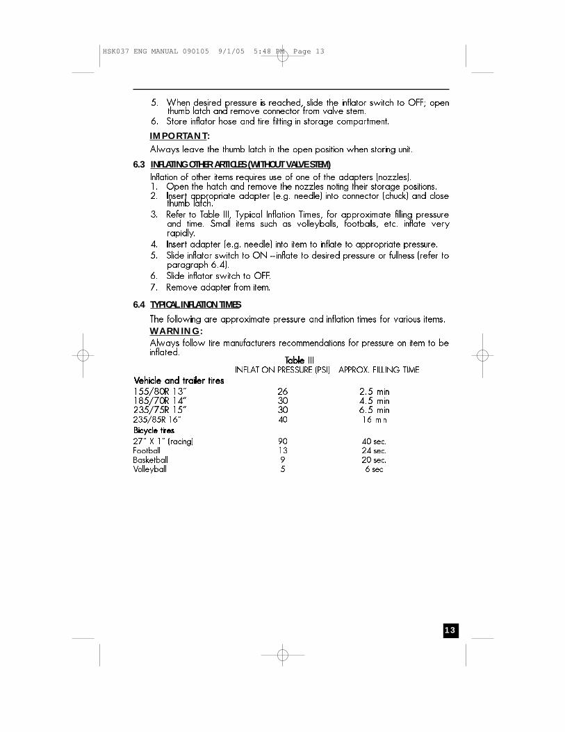
5. When desired pressure is reached, slide the inflator switch to OFF; openthumb latch and remove connector from valve stem.
6. Store inflator hose and tire fitting in storage compartment.
IMPORTANT:Always leave the thumb latch in the open position when storing unit.
6.3 INFLATING OTHER ARTICLES (WITHOUT VALVE STEM)Inflation of other items requires use of one of the adapters (nozzles).1. Open the hatch and remove the nozzles noting their storage positions.2. Insert appropriate adapter (e.g. needle) into connector (chuck) and close
thumb latch.3. Refer to Table III, Typical Inflation Times, for approximate filling pressure
and time. Small items such as volleyballs, footballs, etc. inflate veryrapidly.
4. Insert adapter (e.g. needle) into item to inflate to appropriate pressure.5. Slide inflator switch to ON - inflate to desired pressure or fullness (refer to
paragraph 6.4).6. Slide inflator switch to OFF.7. Remove adapter from item.
6.4 TYPICAL INFLATION TIMES
The following are approximate pressure and inflation times for various items.
WARNING:Always follow tire manufacturers recommendations for pressure on item to beinflated.
TTTTaaaabbbblllleeee IIIIIIIIIIIIINFLATION PRESSURE (PSI) APPROX. FILLING TIME
7. AC POWER SUPPLYThe AC Power Supply is designed for maintaining today's modern life whiletraveling in vans, RVs, automobiles, trucks, or vehicle that has a 12 Volt batterypower supply and a means to recharge those batteries. The HUSKY® PORTABLEPOWER SYSTEM comes with:1. AC On/Off switch - Slide button to turn the AC Power Supply on and off. (See
Figure 3.)2. 120 VAC Power Outlet from a vehicle’sDCaccessory outlet with a DC charging
adapter.3. AC Power Supply ON Status Indicator - Green LED lights when AC outlet is turned
on; orange/red LED lights if unit is overloaded, overheating, or short circuited.4. AC Power Ground Fault Circuit Interrupt (GFCI) - A 3-prong outlet for 120 VAC
appliances which shuts down inverter if leakage or ground fault current isdetected.
5. Internal protective circuits including:• Overload and over-temperature shutdown (activated if AC output exceeds400 watts).
• AC short-circuit shutdown• LowVoltage shutdown• High-input voltage shutdown
The Husky AC Power Supply also incorporates a new cooling technology thatdirectly benefits customers. The new design more efficiently cools the powertransistors and, combined with soft start, dramatically increases reliability andthe product life. ETL listed - Tested to UL458 standards for power inverterssystem for land vehicles.
1
6
5432
FIGURE 3AC POWER SUPPLY PANEL
1 DC accessory outlet2 Air vent3 AC Power Supply ON/OFF switch4 AC Power Supply ON Status indicator5 AC 120 Volt outlet6 Inverter panel cover
7.1 AC POWER SUPPLY CONTROLS AND INDICATORSFigure 3 details the AC Power Supply front panel.
The DC accessory outlet (1) allows the use of appliances that use DC power.
Air vents (2) keep the unit from overheating.
An On/Off Switch (3) turns the AC Power circuitry on and off. TheON/OFF switch can also be used to reset the AC Power after shutdowndue to overvoltage, overload or an over-temperature condition.The On Status Indicator (4) lights when the AC Power Supply is on.The AC outlet (5) allows use of AC appliances.The AC Power Supply (6) covers the AC Power Supply panel when not in use.
1.Turn power switch to on. (The power indicator lights.)2. Plug in appliance and turn the appliance on.
Note: The AC power supply shuts down automatically when the batteryvoltage level is too low. If the orange/red LED lights, a faulty conditionsuch as an overload, overheating or short circuiting has occurred. Turn theAC Power Supply off and unplug the appliance. Wait a few minutes thenturn power back on.
Make sure switch to AC Power Supply is in OFF position.Make clamp connections as described in section 3.1 of this manual.After connections are made properly, turn AC Power Supply switch to ON.
It is recommended that the unit be returned to Customer Service for batteryreplacement. Contact toll-free (800) 916-7004.
WARNING:• Do not dispose of the battery in fire. This may result in an explosion.
• Before disposing of the battery, protect exposed terminals with heavy-dutyelectrical tape to prevent shorting (shorting can result in injury or fire)
• Do not expose battery to fire or intense heat. It may explode.
8.2 FUSE REPLACEMENT (DC ACCESSORY ADAPTER)
1. Remove plug from accessory receptacle. Remove the gold cap by turningcounterclockwise and lifting off.
2. Remove center pin and spring. Remove fuse.
3. Replace fuse with same type and size fuse (8 amp).
4. Replace center pin and spring inside plug.
5. Replace gold cap by turning clockwise onto plug.
8.3. BATTERY DISPOSAL:This unit contains a maintenance-free, non-spillable, sealed lead-acid battery. This battery is fully recyclable and should beaccepted at any location that accepts common automotive starterbatteries. Examples of places that accept these batteries are:County or municipal recycling drop-off centers, scrap metaldealers and retailers who sell automotive replacement lead acidstarter batteries. For more information on recycling this battery,call toll-free (877) 288-7722.
This Husky Power Product is warranted by Home Depot, to the original purchaser only, to be free of defects inmaterials and workmanship for three years from the date of purchase without additional charge. If you believethat this unit is defective during its original two-year warranty period, return the unit with proper proof ofpurchase to the Home Depot store, or you may send the product to Husky Power Products at the address below.
The warranty does not extend to subsequent purchasers or users. Husky Power Products will not be responsiblefor any amount of damage in excess of the retail purchase price of the product under any circumstances.Incidental and consequential damages are specifically excluded from coverage under this warranty.
This product is not intended for commercial use. This warranty does not apply to accessories or damage to unitsfrom misuse or incorrect installation/connection. Misuse includes wiring or connecting to improper polarity powersources.
RETURN/REPAIR POLICY: Defective products, other than accessories, may be returned to Husky Power ProductsAny defective product, other than accessories, that is returned to Husky Power Products within 30 days of thedate of purchase will be replaced free of charge. If such a product is returned more than 30 days but less thanthree years after the purchase date, Husky Power Products will repair the unit or, at its option, replace it free ofcharge.
If the unit is repaired, new or reconditioned replacement parts may be used, at Husky Power Product’s option. Aunit may be replaced with a new or reconditioned unit of the same or comparable design. The repaired orreplaced unit will then be warranted under these terms for the remainder of the warranty period. The customeris responsible for the shipping charges on all returned items after 30 days. During the warranty period, HuskyPower Products will be responsible for the return shipping charges.
LIMITATIONS: This warranty does not cover accessories, bulbs, fuses and batteries, defects resulting from normalwear and tear (including chips, scratches, abrasions, discoloration or fading due to usage or exposure tosunlight), accidents, damage during shipping to our service facility, alterations, unauthorized use or repair,neglect, misuse, abuse, failure to follow instructions for care and maintenance, fire, flood and Acts of God.
If your problem is not covered by this warranty, call our Technical Support Department toll free at (866) 584-5504. for general repair information and charges, if applicable.
STATE LAW RIGHTS: This warranty gives the purchaser specific legal rights; other rights, which vary from stateto state, may apply. Some states do not allow limitations on how long an implied warranty lasts or the exclusionor limitation of incidental or consequential damages, so the exclusions or limitations stated herein may not apply.
TO REQUEST WARRANTY SERVICE FOR THIS PRODUCT: Contact Husky Power Products Technical Support bytelephone, fax or mail. We suggest that you keep the original packaging in case you need to ship the unit. Whenreturning a product, include your name, address, phone number, dated sales receipt (or copy) and a descriptionof the reason for return and product serial number. After repairing or replacing the unit, we will make everyeffortto return it to you within four weeks.
WARRANTY ACTIVATION: Please completeWarranty Activation Card and mail to Husky Power Products. Enter“HSK012HD” as Model and “Jump Start System” as Product Type. All Husky Power Product products must beregistered within 30 days of purchase to activate this warranty. Mail the completed registration form, along witha copy of the original sales receipt to:
ATTN.: CUSTOMER SERVICE / HUSKY POWER PRODUCTS4140 SW 30th Ave., Ft. Lauderdale, FL 33312


![Portable ProductsRAC °] 7500 › mmh › lis_pdf › OWNM › L0403232.pdf · GENPortable ProductsRAC °] 7500 Portable Generator Owner's Manual Model No. 1315-0 (7,500 Watt AC Generator)](https://static.documents.pub/doc/80x56/5f204288361a060b480a464d/portable-productsrac-7500-a-mmh-a-lispdf-a-ownm-a-l0403232pdf-genportable.jpg)


