64
Portable Function Generator 6.111 Final Project Report Fall 2014 Brandon Vasquez Ciara Kamahele 1

Portable Function Generator 6.111 Final Project Report - Fall 2014
Brandon Vasquez Ciara Kamahele
1

Abstract (Both)
A function generator is a universal tool used by every electrical engineer at some point in their career. Sine, square, and triangle waves of different periods, duty cycles, and amplitudes are required as input to many digital and analog circuits. A function generator creates these input signals which can then be amplified and used in a variety of applications. There is currently a wide range of commercial function generators available to choose from, many of them fetching a high price. For our final project, we constructed a function generator using a Nexys 4 FPGA. Using buttons and switches built into the Nexys 4, users are able to select a frequency and have the Nexys 4 generate the corresponding waveform on one of two output channels. Our device produces a VGA signal of the waveforms which is displayable on any VGA monitor. This way, users can view the waveform they are generating without having to verify with a scope. We hope that our function generator will be useful for other fellow electrical engineers, especially students, who would rather purchase a device with a multitude of uses such as an FPGA rather than buying a device that can only work as a function generator. Implementation Overview (Both)
Our project is comprised of three major base modules. The first module, the waveform generator, generates square waves, triangle waves, and sine waves. Using two 8- bit DACs, we implemented dual channel outputs which should be able to display independent waveforms simultaneously. The user is able to control the duty cycle of the square and triangle waves as well as the amplitude and frequency for all three types of waves. The two
2
output channels also have a variable phase shift relative to each other which can be arbitrarily assigned by the user. The second module, the sampling window, chooses an appropriate scaled sample of the current waveforms to be displayed. The window can be varied to display more or less of the waveform as well as scaled for viewability. This module is tasked with mapping the real-time waveform generated by the waveform module to a format that can be displayed using the third module, the display module. The display module interfaces with a VGA display. It communicates directly with the sampling window module to acquire the information it needs to display. As an extension to the base of the project, this module could also be capable of displaying the waveforms using galvanometers. The display module would take the input of the window and translate it into motion for the galvanometers. This way, with a low power laser, the waveforms would be able to be viewed on a flat surface like a wall. The square and triangle waves would be drawn from point to point. For sine waves, we would most likely use a pre computed sine wave table with a reasonable resolution, and draw the signal continuously between discrete points taken from the sine wave table.
Modules
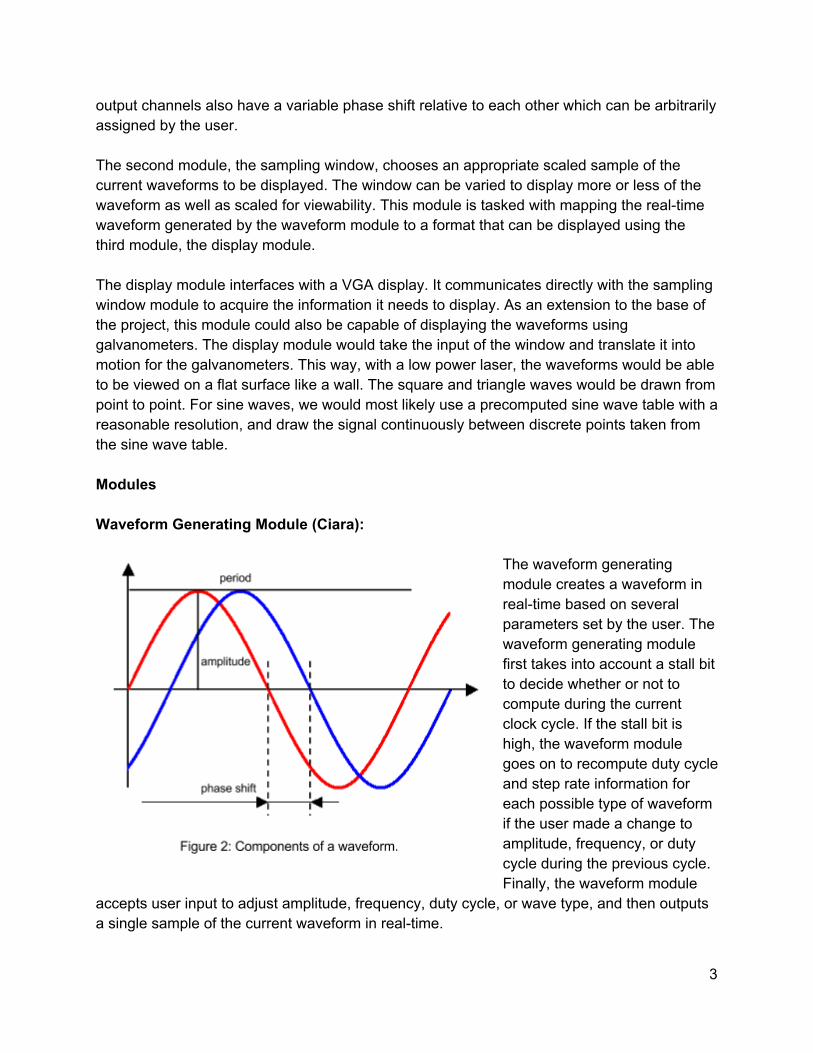
Waveform Generating Module (Ciara):
The waveform generating module creates a waveform in real-time based on several parameters set by the user. The waveform generating module first takes into account a stall bit to decide whether or not to compute during the current clock cycle. If the stall bit is high, the waveform module goes on to recompute duty cycle and step rate information for each possible type of waveform if the user made a change to amplitude, frequency, or duty cycle during the previous cycle. Finally, the waveform module
accepts user input to adjust amplitude, frequency, duty cycle, or wave type, and then outputs a single sample of the current waveform in real-time.
3

The stall bit of the waveform module can be used by an outer module to implement phase shifting between multiple instances of waveform generating modules. If there is only one waveform generating module in use, the stall bit is intended to always remain low. If there are two waveform modules with a variable phase shift in between them, as implemented in our top-level module, the phase shift can be implemented using the stall bits of each waveform. In order to increase the phase shift, the stall bit of the first of the waveforms can be set high. The number of clock cycles the stall bit is held high for, or the phase shift multiplier, can be used to calculate the current phase shift by multiplying this number by the clock period. To decrease the phase shift, the stall bit of the second waveform can be set high. The phase shift multiplier is decreased accordingly by the amount of clock cycles that the stall bit of the second waveform is held high for. User Parameters (Ciara):
The waveform generating module has an adjustable amplitude resolution of 8-12 bits, in order to be compatible with the DACs we chose to use for our project. The waveform amplitude begins at 50% of the maximum amplitude, and can be adjusted up or down by user-accessible buttons. Assuming an output supply voltage of 5V, the amplitude can be changed in increments of approximately ±0.2V, 1V, 1.5V, and 2.5V, capping out at 0V and 5V. This resolution is approximate because it was much more hardware and time efficient to adjust the amplitude by rough addition and subtraction, rather than by exact multiplication and division. The current amplitude is output from the module in approximate millivolts by shifting the current amplitude left by one bit. The waveform generating module has a variable frequency resolution between 1MHz and 1KHz. We implemented several schemes for user frequency adjustment, and eventually settled on the simplest one due to timing issues. Internally, the period of the current waveform is stored as a period multiplier. The period multiplier measures the number of clock cycles contained in the current period. We worked with a 100MHz clock, so a period multiplier of 1 would correspond to a 10 ns period. We made the minimum period multiplier 100, corresponding to a minimum frequency of 1MHz, so that there would be sufficient clock cycles in each period to prevent aliasing of the sine waves. One of the possible schemes we implemented for changing the frequency allowed an adjustment resolution of ±1Hz, 10Hz, 100Hz, 1KHz, 10KHz, or 100KHz. In order to allow such flexibility and fine adjustment of the frequency, we used multipliers and dividers to convert the period into the representation of the same frequency that the period was being adjusted by. Then, we multiplied the frequency by a fraction, to adjust it up or down to the next level. In the case of an upward adjustment, the calculated frequency would be multiplied by n / (n + 1), and in the case of a downward adjustment, the calculated frequency would be multiplied by (n+1) / n. Finally, the frequency would be converted back to a period multiplier and stored.
4

The waveform generating module stores the current duty cycle as a number representing percent duty cycle between 1 and 100. The duty cycle begins at 50%, and the user can change the duty cycle up or down in increments of ±5%, 10%, 20%, or 50%. The duty cycle can easily be incremented up or down internally in this representation with simple addition and subtraction. Finally, the currently displayed wave type can be toggled once during each cycle. A single user button press cycles between square, triangle and sine waves. In order to prevent toggles from happening too quickly, each user button is latched when it goes high for a single clock cycle, and not unlatched until it goes low again for at least a full clock cycle. For simplicity, the user buttons are assigned a priority and only a single button press is handled at a time, using this pre-set priority to break ties. Waveform Generation (Ciara):
In order to display a square wave, a duty cycle maximum count is computed by taking the period multiplier and multiplying it by the current duty cycle percent. To create a square wave, a counter begins and zero and counts up to the period multiplier. If the current duty cycle count is below the duty cycle maximum count, the output waveform sample is equal to the current maximum amplitude. Otherwise, the output waveform sample is equal to zero. Each time the duty cycle or the frequency of the wave is changed, the maximum duty cycle count is recomputed during the next cycle. In order to display a triangle wave, the duty cycle maximum count computed for the square wave is also necessary. Additionally, a triangle step up and step down size are computed so that points on the sides of the triangle can be interpolated simply by adding on the way from 0V to the peak of the triangle and subtracting on the way from the peak of the triangle to 0V to compute the current waveform sample to output. We used fixed-point arithmetic to make the interpolation work better than it would with simple floor division of integers. In order to do this, we added an extra eight fractional bits onto the low end of the step sizes and current triangle height count. Each time the height count was incremented, the augmentation would also include the fractional amount. When the height of the current sample was computed, the fractional bits would be removed to produce a sample of the correct bit length.
5

In order to create sine waves, we used a sine lookup table with 1024 samples. The skip size through the table was calculated with 14 fractional bits, and downsized in the same way as the fixed-point arithmetic described earlier when determining the index of the sine table. The current sine table value is multiplied by the overall waveform amplitude to determine the waveform sample to output. Each time the user makes an adjustment to amplitude, frequency, or duty cycle, new internal information specific to each type of waveform is computed in the following cycle. An adjustment to amplitude requires the step up and step down sizes for the triangle wave to be recomputed. An adjustment to the duty cycle or frequency requires the sine table skip rate and the duty cycle maximum count to be recomputed, and thus requires the triangle step up and down sizes to also be recomputed. Sampling Window Module (Ciara): The sampling window module takes the continuous time waveform created by the waveform generating module as input, and chooses 1024 specific samples to fill a buffer, e.g. to use for display or other purposes. In order to produce a consistent sampling window, the module waits until it detects the start of an increasing waveform. This way, the sampling window will always contain a wave starting from a rising edge. The module then takes 1024 selected samples and writes them to internal BRAM. Finally, the module writes the contents of the BRAM to an external memory and signals that they are ready to be read. The sampling window module has to interface with two different clocks. One of the clocks determines the rate at which it receives real-time samples from the waveform generator, and one of the clocks determines the rate at which it can write the external memory so that connected modules have enough time to read the memory before it is overwritten again. In order to accomplish this, we effectively used two separate state machines within the same module. One state machine governs the loop that writes waveforms to BRAM, and one state machine governs the loop that writes the buffered samples in the BRAM to an external memory source. The state machines interface with each other by reading each other’s internal states and occasionally changing their own states based upon the current state of the other.
6
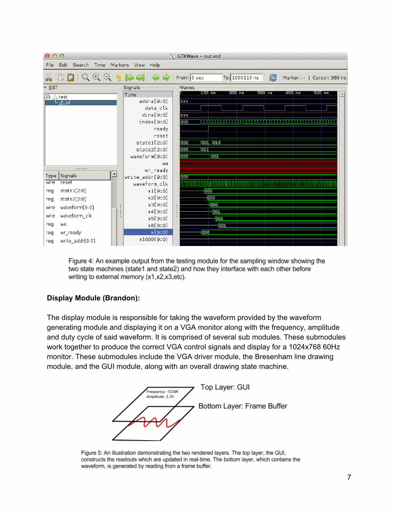
Display Module (Brandon):
The display module is responsible for taking the waveform provided by the waveform generating module and displaying it on a VGA monitor along with the frequency, amplitude and duty cycle of said waveform. It is comprised of several sub modules. These submodules work together to produce the correct VGA control signals and display for a 1024x768 60Hz monitor. These submodules include the VGA driver module, the Bresenham line drawing module, and the GUI module, along with an overall drawing state machine.
7
The display is generated by rendering an upper layer, which is controlled by the GUI module, and a lower layer, which is read from a framebuffer. The lower layer is where the waveforms that are being generated are displayed. Since we only care about whether or not a pixel is part of the waveform, the frame buffer can be constructed out of BRAM with a width of one bit and a depth of the number of pixels in our display. In our implementation, a single BRAM generated using the LogiCore™ is used for the frame buffer. Since the display is 1024x768, we only need one bit for each pixel, so the total size of the BRAM block is 786432 bits (approximately 768Kbits).
On each positive edge of the 65MHz VGA clock, both the output of the frame buffer as well as the GUI module are sent over VGA directly to a monitor. Since our design uses a single frame buffer, writing to the buffer can only occur when the monitor is not drawing anything, i.e. when vsync is low. In this time, if there are any lines to draw, the Bresenham line drawing module will write to the frame buffer memory at the locations which correspond to pixels that are part of the line. Bresenham Module (Brandon):
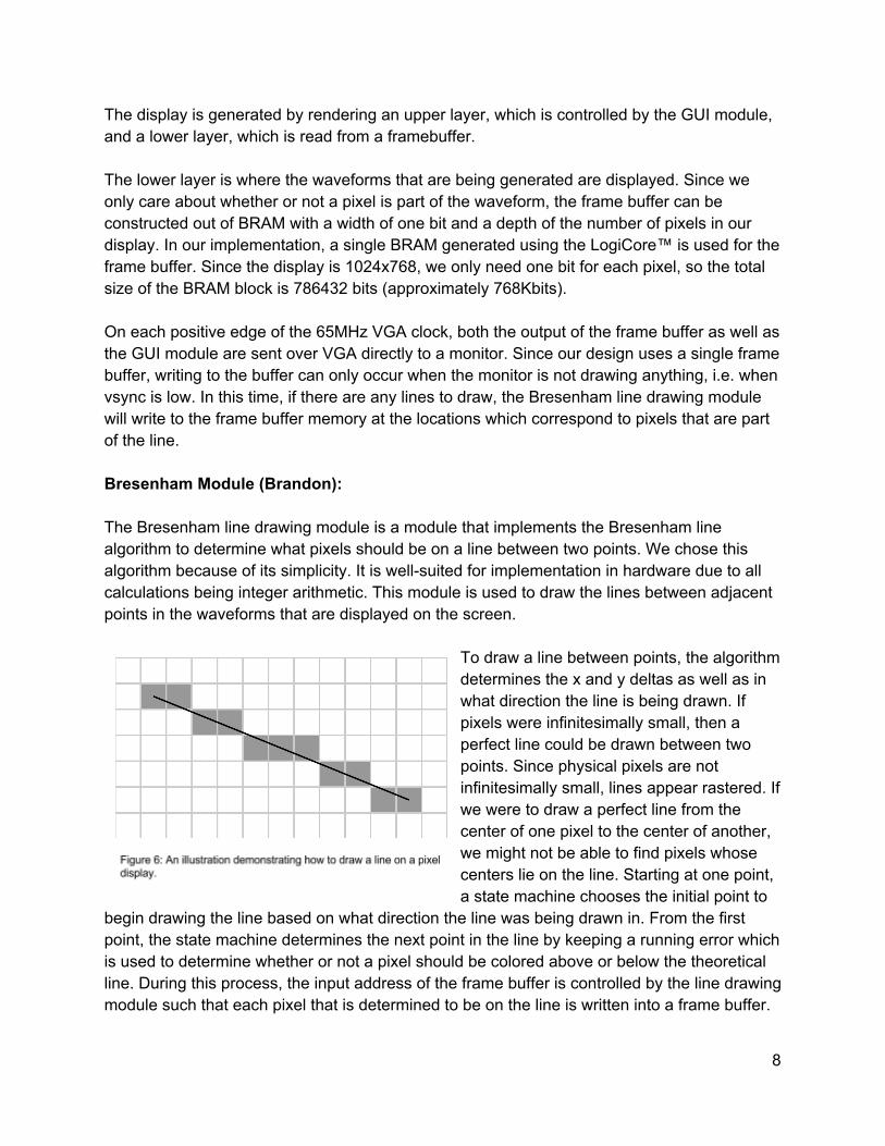
The Bresenham line drawing module is a module that implements the Bresenham line algorithm to determine what pixels should be on a line between two points. We chose this algorithm because of its simplicity. It is well-suited for implementation in hardware due to all calculations being integer arithmetic. This module is used to draw the lines between adjacent points in the waveforms that are displayed on the screen.
To draw a line between points, the algorithm determines the x and y deltas as well as in what direction the line is being drawn. If pixels were infinitesimally small, then a perfect line could be drawn between two points. Since physical pixels are not infinitesimally small, lines appear rastered. If we were to draw a perfect line from the center of one pixel to the center of another, we might not be able to find pixels whose centers lie on the line. Starting at one point, a state machine chooses the initial point to
begin drawing the line based on what direction the line was being drawn in. From the first point, the state machine determines the next point in the line by keeping a running error which is used to determine whether or not a pixel should be colored above or below the theoretical line. During this process, the input address of the frame buffer is controlled by the line drawing module such that each pixel that is determined to be on the line is written into a frame buffer.
8

Display State Machine (Brandon):
To actually draw the entire waveform into memory, a state machine in the display module feeds the line drawing module with points on the generated waveform. These points are stored in BRAM which is shared between the display and the waveform generation modules. When it is time to draw a waveform, the waveform generation module tells the display module that a waveform has been loaded and that it should be drawn. The display state machine clears the current frame buffer and then feeds the points of the waveform to the Bresenham module. First, it provides a pair of points to the line drawing module and tells it to draw that line segment into memory. Once the line drawing module is finished, it reports back to the display module state machine that it is ready to receive the next pair of points. At this time, the display state machine loads the next pair of points into the line drawing module. This cycle continues until the display state machine determines that all pairs of points in the waveform have been drawn.
GUI Module (Brandon):
The GUI module, given an x and y coordinate (hcount and vcount), is responsible for telling whether or not a pixel should be colored if it is part of an alphanumeric readout or the background grid. In the GUI module, a designer can state where they want a letter or number to appear by creating an instance of a text module. A text module contains a large case block
9

which has subcases for each letter. This allows for multiple text sprites to be dynamically loaded in different locations. This process is necessary for dynamic readouts. An instance of a dynamic readout that our system supports is automatically adjusting the frequency and amplitude display to be easily human-readable. For example, a frequency of 1000Hz would
be automatically be displayed as 1.00KHz, and an amplitude of 1234mV would be displayed as 1.23V. The text sprites were hand made using a Python script which would generate the appropriate case block given an array of 1s and 0s, which represents pixels in an 8 by 11 sprite container. BCD, Amplitude, and Frequency Logic (Brandon):
The BCD, amplitude, and frequency modules are responsible for determining what values to display and how to display them. The BCD module takes raw frequency (in Hz) and amplitude (in 10mV) and converts them to binary coded decimal format (BCD). This is done using the double dabble algorithm which is easy to implement in hardware. Given an input of n bits, the BCD module copies it into a register that is n + 4*n bits wide. The first n bits are reserved for the input while the next n*4 bits are used for the BCD representation: each set of 4 bits corresponds to one digit. The register is then shifted left n times. Each time it is shifted, if a digit is equal to or greater than 5, 3 is added to that digit to preserve the carry. The BCD we implemented supports numbers up to 2^20, or 1,048,576, which is plenty for our display. The amplitude and frequency modules are necessary because both of these parameters are modifiable by the user. These modules take the raw amplitude and frequency, along with their BCD representations, and decide what to display given a certain value. For example, if we were trying to display an amplitude of 1234Hz, the frequency logic determines that it is more readable to show “F:1.23KHz” rather than showing “F:1234Hz”.
10

Laser Galvanometer Module (Both):
The laser galvanometer module would be responsible for drawing a waveform on a wall using lasers and galvanometers. To draw an image on a surface, a laser beam is shone on two mirrors. The position of the mirrors determines the termination position of the beam against a wall. The angle of these mirrors is controlled by galvanometers, which maintain a fixed angle
11

given a certain voltage. A mapping can be made between the input voltages of the galvanometers and a cartesian coordinate for the point on a projected surface. This mapping could be stored in BRAM so that the laser galvanometer module could produce the correct voltages to make the laser beam seek to different positions on the wall. To make this mapping, we would assume that the mirrors are close enough together that we can consider them to be a point source. With a point source originating some distance away from the wall, we can use basic trigonometry to determine the angle of the beam relative to the normal, or resting position.
In the figure to the left, we can see a situation where the laser origin is 10 ft away from a projectable surface. If we wanted to deflect the beam from the origin of our viewing plane to 3 feet to the right, we would need to introduce an angle of which is around 16°.rctan( )a 3
10 By rotating the mirror responsible for the horizontal positioning by 16°, we could make the laser beam seek to the right by approximately 3 feet. This same technique could be used to move the beam in the vertical direction, the only difference being the mirror which moves.
Unlike the VGA display which generates images by coloring pixels, galvanometers create persistent images by sweeping a laser beam faster than the human eye can perceive the movement. Since physical limitations prevent the galvanometers from updating their position as fast as a monitor can update pixels, the effectiveness of the galvanometers relies on their ability to interpolate between fewer sampled points. Rather than giving a list of pixels to the galvanometer and turning the laser beam on and off at each pixel, a smaller collection of points can be given to the galvanometer and the laser can trace in between the points without ever being turned off. For example, in order to draw a sine wave which would be encoded for display on VGA as 1024 distinct samples, we would down sample by carefully selecting 100 points on the sine wave for the galvanometer to sequentially update its position.
DAC Modules (Brandon):
Since our project is designed to produce a waveform that can be used not only for a VGA display, but also drawn using laser galvanometers, digital to analog converters (DACs) are
12

necessary to convert the digital representation of a voltage to an analog voltage. DACs have many specifications;; the ones most important to us for our project were resolution, settling time, or how long it takes for a digital input to become a stable analog output, and the number of inputs needed to control the chip. The DAC which produced the waveform would need to have a very small settling time to produce clean waveforms at high frequencies. For example, in order to produce a sine wave at 10KHz, we would need to vary our output voltage at a rate far faster than 10KHz. Assuming we wanted to have 100 samples per period of a 10KHz sine wave, we would have to update the output voltage at 1MHz, which is quite fast for a DAC. As a result, we ended settling on a DAC with parallel inputs. This way, we would be able to use a DAC with a fast settling time to produce high frequency waveforms. The DAC we selected was the 12-bit DAC902 by Texas Instruments. This DAC has an impressive sampling rate of 165 mega samples per second, which makes it great for producing high frequency waves. However, it requires fourteen inputs. Twelve inputs were already needed for the 12 bits of input, while the other two were for control input and reference select. Additionally, one of the applications listed on the data sheet is a function generator, so we thought it would be an appropriate choice. The DAC used for the galvanometers did not have to be nearly as fast as the DAC used for the waveform generation. This is because the galvanometers have a physical limitation that results in a slow maximum update rate of around 30KHz per 8° of shaft rotation. With such a slow output frequency, we could use a slower DAC with serial input which would require far fewer inputs overall. The MCP4822 by Microchip is a small 12-bit dual channel DAC that can be programmed using SPI and has a update rate of about 200KHz. Being an SPI controlled DAC, only 3 inputs are needed: one for the serial clock, one for the data line, and one to latch the input register values to the output voltage. Since the serial clock can not be as fast as the system clock, we generated a new clock using the Logicore clock wizard. Because the system clock works off a 100MHz clock, but the serial clock can be at most 20MHz, synchronization is needed between the input and output of the slower DAC module.
13
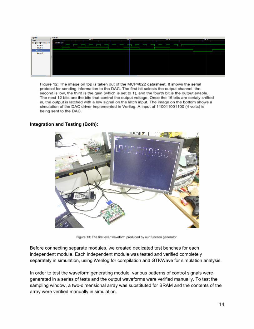
Integration and Testing (Both):
Before connecting separate modules, we created dedicated test benches for each independent module. Each independent module was tested and verified completely separately in simulation, using iVerilog for compilation and GTKWave for simulation analysis. In order to test the waveform generating module, various patterns of control signals were generated in a series of tests and the output waveforms were verified manually. To test the sampling window, a two-dimensional array was substituted for BRAM and the contents of the array were verified manually in simulation.
14

The line drawing was tested by inputting line segments that spanned in between all eight cardinal directions. We verified the line drawing modules performance by monitoring the addresses it was writing to. This module was then added to the hardware and tested with BRAM and the VGA display. The GUI was also tested directly on the display. The DAC modules were tested by comparing the output control signals with the timings and protocols described in their respective datasheets. They were then hooked up to the Nexys 4 and small state machine modules were used to increment and decrement the output voltages based on user input. Once we determined that all initial module worked by themselves, we slowly integrated modules together and tested them as larger units. The first integration we worked on was combining the display module with all of its subunits, because the display was necessary to test and debug all other components. When the display system could successfully draw a precomputed sine wave, we worked on connecting the waveform generating module to the display system. When we could successfully draw a real-time generated square wave, we worked on integrating the other types of waves and accepting and responding to user input. Finally, we worked on integrating the DAC drivers into our system. Challenges (Both): The biggest challenge we faced throughout the project was timing issues. These manifested themselves in the display and caused strange display artifacts. The exact cause for the timing issues was never discovered, but several attempts to remedy artifacts in the display were made. Using the ISE timing reports we were able to find some obvious poor design choices. Unfortunately, there were also other reports which pointed out things that didn’t make sense. An example is a path which included inverters, even though the signal was never inverted. For some of the timing issues that made sense to us, we were able to add delays and some pipelining to reduce the critical path. Another we made attempt at fixing the issue was explicitly creating buffers on the clocks. We had assumed that these had already existed, and after attempting to add them and noticing a drop in performance, we came to the conclusion that they did not need additional buffering. Another problem that was amplified by the latent timing issues was performing complex mathematical operations. While our original scheme for allowing the user to manipulate the waveform frequency very precise and gave the user fine resolution tuning in regards to the output waveform, the hardware produced to do all the multiplications and divisions would interact negatively with the timing constraints and produce surprising outputs. The frequency shifting worked perfectly in simulation but did not work in practice. We tried breaking up the computation of the new frequency over several clock cycles to reduce the amount of necessary hardware and to interact better with the timing constraints, but it didn’t help much. In the end, we ended up implementing several constant fixed-frequency adjustments instead.
15

The math required for these increments was much simpler, and was able to work within the physical timing constraints of our system. Another fix to we attempted to implement was a double frame buffer drawing scheme. We hoped that using a secondary frame buffer would improve the timing of the display module and potentially solving some of our persistent timing issues. In our implemented double buffer scheme, one buffer could be continuously written to while the other buffer was being displayed. Once the waveform was written to memory, the display could switch to the buffer with the new waveform while the buffer it was previously displaying could be cleared and have a new waveform loaded into it. This would have also improved flickering that resulted from a single buffer being viewed during the drawing of a line segment. Ultimately, we used single buffer for simplicity, and our attempts at implementing a double buffer scheme were halted due to more pressing issues and project time constraints. Another considerable challenge we faced was integration of separate modules. While our modules appeared to work well in simulation, it was difficult to put them together in such a way as to not break the display. Because of the timing issues previously mentioned, when we would add computationally difficult modules to the overall project, such as the multipliers and dividers required for fine frequency shift resolution, the display would become significantly distorted. Additionally, attempting to duplex two copies of the waveform generator to implement dual channel output with a phase shift worked in simulation, but did not work in practice due to the hardware requirements and interaction with timing problems. Since we were unable to find the primary source of the timing issues, we had to make several design choices that involved simplifying the control flow and arithmetic. We also faced issues integrating the DACs with our module. We were able to generate analog voltages using the DACs independent of our module. We tested this by using buttons to increment and decrement the output voltage. We were also able to generate a sine wave by directly reading out of BRAM at a slow rate, but unable to generate a sine wave with a varying frequency. We believe this was due to the update rate of the DACs being greater than their theoretical maximum. We attempted to reduce the update rate while preserving the shape of the waveform but were unable to determine whether the bug was in the Verilog generating the waveform or elsewhere.
16

APPENDIX A:
Glossary
bitmap - A data structure that contains information about every single pixel in an image. This information can include things like color, hue and saturation. block random-access memory (BRAM) - Block RAM is dedicated memory which is allocated on demand. digital to analog converter (DAC) - A chip that takes a digital representation of an analog voltage and produces either a proportional analog voltage or current. fixed point arithmetic - A representation for a number that includes a fixed number of digits after the decimal point. frame buffer - A piece of memory that contains a bitmap of an entire frame of the screen which is to be displayed. function generator - An electrical engineering tool that produces waveforms of differing shapes, amplitudes, and frequencies;; also commonly referred to as signal generator. galvanometer - An instrument that sets the angle of a small mirror proportional to the input voltage or current. GUI - A graphical user interface. hcount, vcount - The horizontal and vertical positions of the current pixel being drawn to the monitor. look up table - A table consisting of precomputed values normally associated with complex arithmetic, making it easier to to calculations. For example, a sine look up table would contain precomputed values of sine for given angles, making it easy to “calculate” the sine of an angle in hardware. raster graphics - A method of storing an image as a bitmap as opposed to as a vector. SPI - A synchronous communication scheme that uses few wires. The minimum is a two wire scheme where communication is only in one direction. A serial clock and data line are needed to transmit information. At every pulse of the serial clock, the value on the data line is shifted into a register on the receiving end.
17

bcd.v Page 1
`timescale 1ns / 1ps`default_nettype none/*
This Module was created by Brandon
BCD Module:This module takes in a number and outputs the binary coded decimal version of it.It utilizes the double dabble algorithm which is very fast an efficient.This module supports numbers up to 2^20 = 1,048,576
*/
module bcd(input wire [19:0] number, output reg [3:0] d1_000_000, d100_000,d10_000,d1_000, d100, d10, d1);
// Double dabble algorithm reg [47:0] shift; integer i;
always @(number) begin shift[47:20] = 0; shift[19:0] = number;
for (i=0; i<20; i=i+1) begin if (shift[23:20] >= 5) shift[23:20] = shift[23:20] + 3;
if (shift[27:24] >= 5) shift[27:24] = shift[27:24] + 3;
if (shift[31:28] >= 5) shift[31:28] = shift[31:28] + 3;
if (shift[35:32] >= 5) shift[35:32] = shift[35:32] + 3;
if (shift[39:36] >= 5) shift[39:36] = shift[39:36] + 3;
if (shift[43:40] >= 5) shift[43:40] = shift[43:40] + 3;
shift = shift << 1; end
d1_000_000 = shift[47:44]; // Millions d100_000 = shift[43:40]; // Hundred Thousands place d10_000 = shift[39:36]; // Tens Thousands Place d1_000 = shift[35:32]; // Thousands Place d100 = shift[31:28]; // Hundreds place d10 = shift[27:24]; // Tens place d1 = shift[23:20]; // Ones place end
endmodule

seg_encoder.v Page 1
`timescale 1ns / 1ps//////////////////////////////////////////////////////////////////////////////////// Company: // Engineer: Brandon// // Create Date: 19:32:12 10/11/2014 // Design Name: // Module Name: seg_encoder // Project Name: // Target Devices: // Tool versions: // Description: //// Dependencies: //// Revision: // Revision 0.01 − File Created// Additional Comments: ////////////////////////////////////////////////////////////////////////////////////module seg_encoder( input wire [3:0] in, output reg [6:0] out );
always @(*) begin case(in) 0: out = ~7'b0111111; // 0 1: out = ~7'b0000110; // 1 2: out = ~7'b1011011; // 2 3: out = ~7'b1001111; // 3 4: out = ~7'b1100110; // 4 5: out = ~7'b1101101; // 5 6: out = ~7'b1111101; // 6 7: out = ~7'b0000111; // 7 8: out = ~7'b1111111; // 8 9: out = ~7'b1100111; // 0 10: out = ~7'b1110111; // A 11: out = ~7'b1111100; // b 12: out = ~7'b0111001; // C 13: out = ~7'b1011110; // d 14: out = ~7'b1111001; // E 15: out = ~7'b1110001; // F default: out <= 8'b11111111; default: out = 7'b1111111; endcase end
endmodule

display.c Page 1
`timescale 1ns / 1ps//`default_nettype none//////////////////////////////////////////////////////////////////////////////////// Company: // Engineer: Brandon// // Create Date: 14:33:50 12/06/2014 // Design Name: // Module Name: display // Project Name: // Target Devices: // Tool versions: // Description: //// Dependencies: //// Revision: // Revision 0.01 − File Created// Additional Comments: ////////////////////////////////////////////////////////////////////////////////////module display( input wire clk, reset, center, right, left, up, down, input wire [8:0] douta, input wire [19:0] freq, input wire [8:0] amp, input wire [6:0] duty_cycle, output wire [11:0] rgb, output wire hsync, output wire vsync, output wire vclk, output reg [9:0] addra, output reg ready, output reg current_frame_buf ); parameter SCREEN_WIDTH = 1024; parameter SCREEN_HEIGHT = 768; wire [10:0] hcount; wire [9:0] vcount; wire blank; // Produces the vga signals needed VGADriver vga(.clk(clk),.hcount(hcount),.vcount(vcount), .hsync(hsync),.vsync(vsync),.blank(blank),.vclk(vclk));
reg debug; wire mem_out,mem_out1;
wire write_out; reg clear = 0; reg [10:0] cursorX; reg [9:0] cursorY;
wire [10:0] xAddr; wire [9:0] yAddr; // Creates a pulse when vsync goes low reg pre_vsync = 0; wire sync_pulse; assign sync_pulse = ((pre_vsync == 1) && (vsync == 0)); // When pressing clear we dont want to display // things from memory (since its being cleared) wire d; assign d = clear ? 0 : mem_out; // Output of the GUI module wire text_out; assign rgb = 12(hcount==0 | hcount==1023 | vcount==0 | vcount==767) | 12(hcount == cursorX && vcount == cursorY) | 12text_out | 12d; // Addresses used for looking up values in video frame buffer

display.c Page 2
wire [19:0] vga_address; wire [19:0] line_address; wire [19:0] a,a1; assign vga_address = hcount + (SCREEN_WIDTH * vcount); assign line_address = xAddr + (SCREEN_WIDTH * yAddr); assign a = clear ? clearcount :(vsync ? vga_address : line_address); wire mem_in,mem_in1; assign mem_in = clear ? 0 : 1;//clear ? 1'b0 : 1'b1; assign mem_in1 = clear ? 0 : 1; wire we; assign we = clear? 1 : (vsync?0:write_out); wire we1,we2; //assign w1 = we ? 1 : 0; assign we1 = current_frame_buf ? (clear ? 1 : write_out): 0; // Logicore BRAM vbuff1 video_buff1(vclk, we, a, mem_in, mem_out); //vbuff1 video_buff2(vclk, we1, a1, mem_in1, mem_out1); // bresenham line drawing algorithm reg line_enable; wire bresenham_ready; reg [10:0] x0; reg [10:0] x1; reg [10:0] y0; reg [10:0] y1;
bresenham line(vclk, reset, vsync, line_enable, x0, y0[9:0], x1, y1[9:0], bresenham_ready, xAddr, yAddr, write_out);
// Cursor controllable with the buttons, used for debuggingalways @ (posedge vclk) begin pre_vsync <= vsync; if((pre_vsync == 1) && (vsync == 0))begin if(~reset) begin cursorX <= SCREEN_WIDTH/2; cursorY <= SCREEN_HEIGHT/2; end else begin cursorX <= right ? (cursorX + 10) : (left ? cursorX − 10 : cursorX); cursorY <= up ? (cursorY − 10) : (down ? (cursorY + 10) : cursorY); end endend
reg [2:0] display_state = 0;
parameter WAITING = 3'd0;parameter SETUP = 3'd1;parameter CLEAR = 3'd2;parameter LOAD_WAVE_STATE_0 = 3'd3;parameter LOAD_WAVE_STATE_1 = 3'd4;parameter SEND_TO_LINE = 3'd5;parameter WAIT_FROM_LINE = 3'd6;parameter RESET = 3'd7;
reg [10:0] smalldelay;parameter DELAY = 40;parameter SAMPLESIZE = 1023;parameter xstepsize = 1;parameter HALF_MAX_AMP = 256;
reg newvsync;reg [19:0] clearcount ;reg upbutton, rightbutton, leftbutton, downbutton;reg [5:0] xscale;
display.c Page 3
reg [5:0] yscale;reg new_slate = 0;
always @ (posedge vclk) begin if(~reset) begin addra <= 10'd0; clear <= 1; smalldelay <= DELAY; newvsync <= 0; xscale <= 0; yscale <= 1; upbutton <= 0; clearcount <= 0; display_state <= CLEAR; current_frame_buf <= 0; end else begin case(display_state) RESET: begin // Reset default values and clear the display addra <= 10'd0; clear <= 0; debug <= 0; smalldelay <= DELAY; display_state <= CLEAR; newvsync <= 0; upbutton <= 0; end CLEAR: begin // We can clear memmory if(clearcount < 1048575) begin clearcount <= clearcount + 1; end else begin clearcount <= 0; clear <= 0; if(new_slate) begin new_slate <= 0; display_state <= LOAD_WAVE_STATE_0; end else begin display_state <= WAITING; end end end WAITING: begin if(center) begin // begin drawing a line new_slate <= 1; clear <= 1; display_state <= CLEAR; end else begin addra <= 0; end if(right) begin if(~rightbutton) begin // Increase the number of periods xscale <= xscale + 1; rightbutton <= 1; dac_in <= (dac_in + 10); end end else if(left) begin // change the horizontal scale if(~leftbutton) begin if(xscale > 0) begin xscale <= xscale − 1; end leftbutton <= 1; dac_in <= (dac_in − 10); end end else if (up) begin

display.c Page 4
if(~upbutton) begin // change the vertical scale if(yscale > 1) begin yscale <= yscale − 1; end end upbutton <= 1; end else if (down) begin // change the horizontal scale if(~downbutton) begin yscale <= yscale + 1; end downbutton <= 1; end else begin upbutton <= 0; rightbutton <= 0; leftbutton <= 0; downbutton <= 0; end end LOAD_WAVE_STATE_0: begin // Now we can draw whats in the waveform buffer // Load up initial x0,x1,y0,y1 debug <= 1; x0 <= 11'd0; x1 <= 11'd0; y0 <= SCREEN_HEIGHT/2 − douta/yscale;//HALF_MAX_AMP/yscale + douta/yscale; smalldelay <= DELAY; addra <= addra + (1<<xscale); display_state <= LOAD_WAVE_STATE_1; end LOAD_WAVE_STATE_1: begin // Loads up the x1 and y1 coordinates dac_send <= 0; if(smalldelay > 0) begin x1 <= x1 + 11'd1; y1 <= SCREEN_HEIGHT/2 − douta/yscale;//HALF_MAX_AMP/yscale + douta/yscale; smalldelay <= DELAY; display_state <= SEND_TO_LINE; end else begin smalldelay <= smalldelay − 1; end end SEND_TO_LINE: begin // Send the pair to the line drawing algorithm if(smalldelay > 0) begin smalldelay <= smalldelay − 1; end else begin if(~vsync) begin newvsync <= 1; line_enable <= 1; smalldelay <= DELAY; display_state <= WAIT_FROM_LINE; end end end WAIT_FROM_LINE: begin // wait until the line drawing algorithm is done line_enable <= 0; if(bresenham_ready) begin if(x1 == 1023) begin display_state <= RESET; current_frame_buf <= ~current_frame_buf; end else begin x0 <= x1; y0 <= y1; addra <= addra + (1 << xscale); display_state <= LOAD_WAVE_STATE_1;

display.c Page 5
end end end default: begin display_state <= RESET; end endcase endend gui g(hcount,vcount,freq,amp,duty_cycle,text_out); endmodule
buffer_fill.v Page 1
//Ciaramodule buffer_fill ( input wire reset, input wire waveform_clk, input wire data_clk, input wire [9:0] waveform, input wire ready, output reg wr_ready, output reg [9:0] addra, output reg we, output wire [9:0] dina);
parameter waiting = 3'd0; parameter checking = 3'd1; parameter collecting = 3'd2; parameter wait_ready = 3'd3; parameter writing = 3'd4; parameter disable_we = 3'd5; parameter disable_wr_ready = 3'd6; parameter delay = 3'd7;
reg [2:0] state1 = waiting; reg [2:0] state2 = waiting;
reg [9:0] delay_count = 10'd0; parameter max_delay_count = 10'd200; reg [9:0] index = 10'd0; reg [9:0] write_addr = 10'd0; wire wave_clk; assign wave_clk = (state2 == writing) ? data_clk : waveform_clk; wire [9:0] a; assign a = (state2 == writing) ? write_addr : index; wire we_bram; assign we_bram = (state2 == writing) ? 0 : 1; mybram #(.LOGSIZE(10),.WIDTH(10)) waveform_buffer(.addr(a),.clk(wave_clk),.we(we_bram),.din(waveform),.dout(dina)); always@(posedge waveform_clk) begin if (~reset) begin state1 <= waiting; index <= 10'd0; end else if (state2 == waiting) begin state1 <= waiting; // wait until we get a zero sample end else if (state1 == waiting) begin if (waveform == 0) begin index <= 10'd1; state1 <= checking; end // make sure waveform is increasing end else if (state1 == checking) begin // waveform is increasing if (waveform > 0) begin index <= index + 1; state1 <= collecting; // waveform is decreasing end else if (waveform < 0) begin index <= 10'd0; state1 <= waiting; end // collect waveform samples end else if (state1 == collecting) begin index <= index + 1; // all samples have been collected if (index == 10'd1023) begin
buffer_fill.v Page 2
state1 <= wait_ready; end end end
always@(posedge data_clk) begin if (~reset) begin state2 <= waiting; wr_ready <= 1'd0; we <= 1'd0; delay_count <= 10'd0; end else if (state1 == waiting) begin state2 <= wait_ready; end else if (state1 == wait_ready) begin // wait for ready to be asserted if (state2 == wait_ready) begin if (ready) begin state2 <= writing; write_addr <= 0; end // write to memory end else if (state2 == writing) begin we <= 1'd1; addra <= write_addr; write_addr <= write_addr + 1; if (write_addr == 10'd1023) begin state2 <= disable_we; end // disable we and wr_ready end else if (state2 == disable_we) begin we <= 1'd0; wr_ready <= 1'd1; state2 <= disable_wr_ready; end else if (state2 == disable_wr_ready) begin wr_ready <= 1'd0; state2 <= delay; delay_count <= 10'd0; end else if (state2 == delay) begin delay_count <= delay_count + 1; if (delay_count == max_delay_count) begin delay_count <= 10'd0; state2 <= waiting; end end end endendmodule
waveform_gen.v Page 1
//Ciara
module waveform_gen( input wire clk, input wire reset, input wire toggle_wave_type, input wire [1:0] incr_res, input wire param, input wire up, // param = 0 −> frequency, 1 −> amplitude input wire down, input wire left, // param = 0 −> duty cycle, 1 −> phase input wire right, input wire stall, output reg [19:0] frequency, // Hz output reg [8:0] amplitude, // 0 −> 255 output reg [9:0] waveform, output reg [6:0] duty_cycle);
parameter max_height = 16'd255; parameter min_height = 16'd0;
parameter clk_period = 1'd1; // 100 MHz = 10 ns parameter min_period_mult = 30'd100; // 1 MHz parameter max_period_mult = 30'd100_000_000; // 1 KHz reg [39:0] period_mult = 40'd1_000; // must be a multiple of 10
parameter min_duty_cycle = 7'd1; parameter max_duty_cycle = 7'd100; reg [39:0] duty_cycle_max_count; reg recalculate_wave_info = 1'd1;
reg [1:0] wave_type = 2'd0; // cycles between square (0), triangle (1), sine (2) reg [39:0] duty_cycle_count = 30'd0; reg [19:0] triangle_height_count; reg [19:0] triangle_step_up_size; reg [19:0] triangle_step_down_size; reg recalculate_triangle_step_size = 1'd0; wavegen_sine_lut sine_table(clk, 0, sine_index, 0, sine_out);
reg [23:0] sine_index_long = 24'd0; reg [23:0] sine_skip = 24'd0; wire [9:0] sine_index; assign sine_index = sine_index_long[23:14]; wire [7:0] sine_out; reg [39:0] sine_count = 40'd0;
reg toggle_button = 1'd0; reg up_button = 1'd0; reg down_button = 1'd0; reg left_button = 1'd0; reg right_button = 1'd0;
reg [15:0] height; // 0 −> 255
always@(posedge clk) begin if (~stall) begin // set amplitude amplitude <= (height[7:0] << 1);
// reset initial values if (~reset) begin height <= 16'd127;
period_mult <= 40'd1_000;
duty_cycle <= 7'd50; duty_cycle_count <= 7'd0; recalculate_wave_info <= 1'd1;
wave_type <= 2'd2; duty_cycle_count <= 40'd0; triangle_height_count <= 30'd0;
waveform_gen.v Page 2
recalculate_triangle_step_size <= 1'd0;
sine_index_long <= 24'd0; sine_skip <= 24'd0; sine_count <= 40'd0;
toggle_button <= 1'd0; up_button <= 1'd0; down_button <= 1'd0; left_button <= 1'd0; right_button <= 1'd0; end else begin // recalculate duty cycle and triangle step size if (recalculate_wave_info) begin duty_cycle_max_count <= (period_mult * duty_cycle / max_duty_cycle); triangle_step_up_size <= ((height << 8) / (period_mult * duty_cycle / max_duty_cycle)); triangle_step_down_size <= ((height << 8) / (period_mult − (period_mult * duty_cycle / max_duty_cycle)));
duty_cycle_count <= 20'd0; triangle_height_count <= 20'd0;
sine_skip <= (1024 << 14) / period_mult;
recalculate_wave_info <= 1'd0; recalculate_triangle_step_size <= 1'd0; // recalculate triangle step size end else if (recalculate_triangle_step_size) begin triangle_step_up_size <= ((height << 8) / duty_cycle_max_count); triangle_step_down_size <= ((height << 8) / (period_mult − duty_cycle_max_count));
duty_cycle_count <= 20'd0; triangle_height_count <= 20'd0;
recalculate_triangle_step_size <= 1'd0; end
// cycle through wave types if (toggle_wave_type) begin if (~toggle_button) begin wave_type <= ((wave_type + 1) < 3 )? (wave_type + 1) : 0; end toggle_button <= 1; end else begin toggle_button <= 0; end
// handle up/down/left/right if (up) begin if (~up_button) begin if (param) begin // amplitude up case (incr_res[1:0]) 2'd0: height <= ((height + 1) > max_height) ? max_height : (height + 1); // ~0.2 V 2'd1: height <= ((height + 5) > max_height) ? max_height : (height + 5); // ~1 V 2'd2: height <= ((height + 8) > max_height) ? max_height : (height + 8); // ~1.5 V 2'd3: height <= ((height + 13) > max_height) ? max_height : (height + 13); // ~2.5 V endcase recalculate_triangle_step_size <= 1'd1; end else begin // 1 clk = 10 ns // period in ns = period_mult * 10; // 1 s = 1_000_000_000 ns // Hz = 1 / s // 1000 Hz = 1 KHz = 1000 / s // 1 KHz = 1 / 1_000_000 ns // 1 Hz = 1 / 1_000_000_000 ns

waveform_gen.v Page 3
// freq in Hz = 1_000_000_000 / (period_mult * 10) // freq in 10 Hz = 100_000_000 / (period_mult * 10) // freq in 100 Hz = 10_000_000 / (period_mult * 10) // freq in KHz = 1_000_000 / (period_mult * 10) // freq in 10 KHz = 100_000 / (period_mult * 10) // freq in 100 KHz = 10_000 / (period_mult * 10) // freq in MHz = 1_000 / (period_mult * 10)
// frequency up, period down
/*case (period_mult) // 100 −> 200 KHz 1_000: period_mult <= 500;
// 200 −> 400 KHz 500: period_mult <= 250;
// 400 −> 800 KHz 250: period_mult <= 125;
endcase*/
case (incr_res) // +1 Hz // n = 1_000_000_000 / (period_mult * 10) // period_mult = period mult * n / (n + 1) 3'd0: period_mult <= (((period_mult * (1_000_000_000 / (period_mult * 10)) / ((1_000_000_000 / (period_mult * 10)) + 1)) > period_mult) || ((period_mult * (1_000_000_000 / (period_mult * 10)) / ((1_000_000_000 / (period_mult * 10)) + 1)) < min_period_mult)) ? min_period_mult : (period_mult * (1_000_000_000 / (period_mult * 10)) / ((1_000_000_000 / (period_mult * 10)) + 1)); // +10 Hz // n = 100_000_000 / (period_mult * 10) // period_mult = period mult * n / (n + 1) 3'd1: period_mult <= (((period_mult * (100_000_000 / (period_mult * 10)) / ((100_000_000 / (period_mult * 10)) + 1)) > period_mult) || ((period_mult * (100_000_000 / (period_mult * 10)) / ((100_000_000 / (period_mult * 10)) + 1)) < min_period_mult)) ? min_period_mult : (period_mult * (100_000_000 / (period_mult * 10)) / ((100_000_000 / (period_mult * 10)) + 1)); // +100 Hz // n = 10_000_000 / (period_mult * 10) // period_mult = period mult * n / (n + 1) 3'd2: period_mult <= (((period_mult * (10_000_000 / (period_mult * 10)) / ((10_000_000 / (period_mult * 10)) + 1)) > period_mult) || ((period_mult * (10_000_000 / (period_mult * 10)) / ((10_000_000 / (period_mult * 10)) + 1)) < min_period_mult)) ? min_period_mult : (period_mult * (10_000_000 / (period_mult * 10)) / ((10_000_000 / (period_mult * 10)) + 1)); // +1 KHz // n = 1_000_000 / (period_mult * 10) // period_mult = period mult * n / (n + 1) 3'd3: period_mult <= (((period_mult * (1_000_000 / (period_mult * 10)) / ((1_000_000 / (period_mult * 10)) + 1)) > period_mult) || ((period_mult * (1_000_000 / (period_mult * 10)) / ((1_000_000 / (period_mult * 10)) + 1)) < min_period_mult)) ? min_period_mult : (period_mult * (1_000_000 / (period_mult * 10)) / ((1_000_000 / (period_mult * 10)) + 1)); // +10 KHz // n = 100_000 / (period_mult * 10) // period_mult = period mult * n / (n + 1) 3'd4: period_mult <= (((period_mult * (100_000 / (period_mult * 10)) / ((100_000 / (period_mult * 10)) + 1)) > period_mult) || ((period_mult * (100_000 / (period_mult * 10)) / ((100_000 / (period_mult * 10)) + 1)) < min_period_mult)) ? min_period_mult : (period_mult * (100_000 / (period_mult * 10)) / ((100_000 / (period_mult * 10)) + 1)); // +100 KHz // n = 10_000 / (period_mult * 10) // period_mult = period mult * n / (n + 1) 3'd5: period_mult <= (((period_mult * (10_000 / (period_mult * 10)) / ((10_000 / (period_mult * 10)) + 1)) > period_mult) || ((period_mult * (10_000 / (period_mult * 10)) / ((10_000 / (period_mult * 10)) + 1)) < min_period_mult)) ?

waveform_gen.v Page 4
min_period_mult : (period_mult * (10_000 / (period_mult * 10)) / ((10_000 / (period_mult * 10)) + 1)); endcase recalculate_wave_info <= 1'd1; end end up_button <= 1; end else if (down) begin if (~down_button) begin if (param) begin // amplitude down case (incr_res[1:0]) 2'd0: height <= ((height − 1) > height) ? min_height : (height − 1); // ~0.2 V 2'd1: height <= ((height − 5) > height) ? min_height : (height − 5); // ~1 V 2'd2: height <= ((height − 8) > height) ? min_height : (height − 8); // ~1.5 V 2'd3: height <= ((height − 13) > height) ? min_height : (height − 13); // ~2.5 V endcase recalculate_triangle_step_size <= 1'd1; end else begin // frequency down, period up
/*case (period_mult) // 800 −> 400 KHz 125: period_mult <= 250;
// 400 −> 200 KHz 250: period_mult <= 500;
// 200 −> 100 KHz 500: period_mult <= 1_000;
endcase*/
case (incr_res) // −1 Hz // n = 1_000_000_000 / (period_mult * 10) // period_mult = period mult * n / (n − 1) 3'd0: period_mult <= (((1_000_000_000 / (period_mult * 10))− 1) == 0) ? period_mult : ((((period_mult * (1_000_000_000 / (period_mult * 10)) / ((1_000_000_000 / (period_mult * 10)) − 1)) < period_mult) || ((period_mult * (1_000_000_000 / (period_mult * 10)) / ((1_000_000_000 / (period_mult * 10)) − 1)) > max_period_mult)) ? max_period_mult : (period_mult * (1_000_000_000 / (period_mult * 10)) / ((1_000_000_000 / (period_mult * 10)) − 1))); // −10 Hz // n = 100_000_000 / (period_mult * 10) // period_mult = period mult * n / (n − 1) 3'd1: period_mult <= (((100_000_000 / (period_mult * 10))− 1) == 0) ? period_mult : ((((period_mult * (100_000_000 / (period_mult * 10)) / ((100_000_000 / (period_mult * 10)) − 1)) < period_mult) || ((period_mult * (100_000_000 / (period_mult * 10)) / ((100_000_000 / (period_mult * 10)) − 1)) > max_period_mult)) ? max_period_mult : (period_mult * (100_000_000 / (period_mult * 10)) / ((100_000_000 / (period_mult * 10)) − 1))); // −100 Hz // n = 10_000_000 / (period_mult * 10) // period_mult = period mult * n / (n − 1) 3'd2: period_mult <= (((10_000_000 / (period_mult * 10))− 1) == 0) ? period_mult : ((((period_mult * (10_000_000 / (period_mult * 10)) / ((10_000_000 / (period_mult * 10)) − 1)) < period_mult) || ((period_mult * (10_000_000 / (period_mult * 10)) / ((10_000_000 / (period_mult * 10)) − 1)) > max_period_mult)) ? max_period_mult : (period_mult * (10_000_000 / (period_mult * 10)) / ((10_000_000 / (period_mult * 10)) − 1))); // −1 KHz // n = 1_000_000 / (period_mult * 10) // period_mult = period mult * n / (n − 1) 3'd3: period_mult <= (((1_000_000 / (period_mult * 10))− 1) == 0) ? period_mult :
waveform_gen.v Page 5
((((period_mult * (1_000_000 / (period_mult * 10)) / ((1_000_000 / (period_mult * 10)) − 1)) < period_mult) || ((period_mult * (1_000_000 / (period_mult * 10)) / ((1_000_000 / (period_mult * 10)) − 1)) > max_period_mult)) ? max_period_mult : (period_mult * (1_000_000 / (period_mult * 10)) / ((1_000_000 / (period_mult * 10)) − 1))); // −10 KHz // n = 100_000 / (period_mult * 10) // period_mult = period mult * n / (n − 1) 3'd4: period_mult <= (((100_000 / (period_mult * 10))− 1) == 0) ? period_mult : ((((period_mult * (100_000 / (period_mult * 10)) / ((100_000 / (period_mult * 10)) − 1)) < period_mult) || ((period_mult * (100_000 / (period_mult * 10)) / ((100_000 / (period_mult * 10)) − 1)) > max_period_mult)) ? max_period_mult : (period_mult * (100_000 / (period_mult * 10)) / ((100_000 / (period_mult * 10)) − 1))); // −100 KHz // n = 10_000 / (period_mult * 10) // period_mult = period mult * n / (n − 1) //3'd5: period_mult <= 1; 3'd5: period_mult <= (((10_000 / (period_mult * 10))− 1) == 0) ? period_mult : ((((period_mult * (10_000 / (period_mult * 10)) / ((10_000 / (period_mult * 10)) − 1)) < period_mult) || ((period_mult * (10_000 / (period_mult * 10)) / ((10_000 / (period_mult * 10)) − 1)) > max_period_mult)) ? max_period_mult : (period_mult * (10_000 / (period_mult * 10)) / ((10_000 / (period_mult * 10)) − 1))); endcase recalculate_wave_info <= 1'd1; end end down_button <= 1; end else if (left) begin if (~left_button) begin // duty cycle down case (incr_res) 2'd0: duty_cycle <= ((duty_cycle − 5) > duty_cycle) ? min_duty_cycle : (duty_cycle − 5); 2'd1: duty_cycle <= ((duty_cycle − 10) > duty_cycle) ? min_duty_cycle : (duty_cycle − 10); 2'd2: duty_cycle <= ((duty_cycle − 20) > duty_cycle) ? min_duty_cycle : (duty_cycle − 20); 2'd3: duty_cycle <= ((duty_cycle − 50) > duty_cycle) ? min_duty_cycle : (duty_cycle − 50); endcase recalculate_wave_info <= 1'd1; end left_button <= 1; end else if (right) begin if (~right_button) begin // duty cycle up case (incr_res) 2'd0: duty_cycle <= (((duty_cycle + 5) > max_duty_cycle) || ((duty_cycle + 5) < duty_cycle)) ? max_duty_cycle : (duty_cycle + 5); 2'd1: duty_cycle <= (((duty_cycle + 10) > max_duty_cycle) || ((duty_cycle + 10) < duty_cycle)) ? max_duty_cycle : (duty_cycle + 10); 2'd2: duty_cycle <= (((duty_cycle + 20) > max_duty_cycle) || ((duty_cycle + 20) < duty_cycle)) ? max_duty_cycle : (duty_cycle + 20); 2'd3: duty_cycle <= (((duty_cycle + 50) > max_duty_cycle) || ((duty_cycle + 50) < duty_cycle)) ? max_duty_cycle : (duty_cycle + 50); endcase recalculate_wave_info <= 1'd1; end right_button <= 1; end else begin up_button <= 0; down_button <= 0; left_button <= 0; right_button <= 0; end
waveform_gen.v Page 6
// calculate frequency frequency <= 1_000_000_000 / (period_mult * 10); // Hz
// generate waveform // square wave if (wave_type == 0) begin if (duty_cycle_count < duty_cycle_max_count) begin waveform <= height[7:0]; end else begin waveform <= 0; end duty_cycle_count <= ((duty_cycle_count + 1) < period_mult) ? (duty_cycle_count + 1) : 0; // triangle wave end else if (wave_type == 1) begin // beginning of triangle if (duty_cycle_count == 0) begin waveform <= 0; triangle_height_count <= triangle_step_up_size; // before triangle peak end else if (duty_cycle_count < duty_cycle_max_count − 1) begin waveform <= (triangle_height_count > (height << 8)) ? height[7:0] : (triangle_height_count >> 8); triangle_height_count <= (((triangle_height_count + triangle_step_up_size) > (height << 8)) || ((triangle_height_count + triangle_step_up_size) < triangle_height_count)) ? (height << 8) : (triangle_height_count + triangle_step_up_size);
// triangle peak end else if (duty_cycle_count == duty_cycle_max_count) begin waveform <= height[7:0]; triangle_height_count <= (height << 8); // after triangle peak end else begin waveform <= ((triangle_height_count − triangle_step_down_size) > triangle_height_count) ? min_height : ((triangle_height_count − triangle_step_down_size) >> 8); triangle_height_count <= ((triangle_height_count − triangle_step_down_size) > triangle_height_count) ? min_height : (triangle_height_count − triangle_step_down_size); end duty_cycle_count <= ((duty_cycle_count + 1) < period_mult) ? (duty_cycle_count + 1) : 0; // sine wave end else if (wave_type == 2) begin if (sine_count == 0) begin sine_index_long <= 0; end else begin sine_index_long <= sine_index_long + sine_skip; end waveform <= sine_out * height[7:0] / max_height; sine_count <= ((sine_count + 1) < period_mult) ? (sine_count + 1) : 0; end end end endendmodule
gui.v Page 1
`timescale 1ns / 1ps//`default_nettype none//////////////////////////////////////////////////////////////////////////////////// Company: // Engineer: Brandon// // Create Date: 15:02:40 12/04/2014 // Design Name: // Module Name: gui // Project Name: // Target Devices: // Tool versions: // Description: //// Dependencies: //// Revision: // Revision 0.01 − File Created// Additional Comments: ////////////////////////////////////////////////////////////////////////////////////module gui( input wire [10:0] hcount, input wire [9:0] vcount, input wire [19:0] freq, input wire [8:0] amp, input wire [6:0] duty_cycle, output wire pixel );
parameter COL1 = 10; parameter LINE1 = 10; parameter LINE2 = 22; parameter LINE3 = 34; wire pixF, pixF1, pixF2, pixF3, pixF4, pixF5, pixF6, pixF7, pixA, pixA1, pixA2, pixA3, pixA4, pixA5, pixA6, pixA7, pix0, pix1, pix2, pix3, pix4, pix5, pix6, pix7, pix8, pix9; wire [3:0] f1_000_000, f100_000, f10_000, f1_000, f100, f10, f1; wire [4:0] pixF2_in, pixF3_in, pixF4_in, pixF5_in, pixF6_in, pixF7_in, pixF8_in, pixF9_in, pixF10_in; // Turns the binary representation of the freq into BCD format bcd bcd_freq(freq, f1_000_000, f100_000, f10_000, f1_000, f100, f10, f1); // Handels the logic for displaying freq_logic f_logic(freq, f1_000_000, f100_000, f10_000, f1_000, f100, f10, f1, pixF10_in,pixF9_in,pixF8_in,pixF7_in,pixF6_in,pixF5_in,pixF4_in, pixF3_in,pixF2_in); //Used to create the text overlay // freq text F(COL1 ,LINE1,hcount,vcount,10,pixF); text F_1(COL1*2,LINE1,hcount,vcount,20,pixF1); text F_2(COL1*3,LINE1,hcount,vcount,pixF2_in,pixF2); text F_3(COL1*4,LINE1,hcount,vcount,pixF3_in,pixF3); text F_4(COL1*5,LINE1,hcount,vcount,pixF4_in,pixF4); text F_5(COL1*6,LINE1,hcount,vcount,pixF5_in,pixF5); text F_6(COL1*7,LINE1,hcount,vcount,pixF6_in,pixF6); text F_7(COL1*8,LINE1,hcount,vcount,pixF7_in,pixF7);
gui.v Page 2
wire [3:0] a1_000_000, a100_000, a10_000, a1_000, a100, a10, a1; wire [4:0] pixA2_in, pixA3_in, pixA4_in, pixA5_in, pixA6_in, pixA7_in, pixA8_in, pixA9_in, pixA10_in; // Turns the binary representation of the amp into BCD format bcd bcd_amp(amp, a1_000_000, a100_000, a10_000, a1_000, a100, a10, a1); // Handels the logic for displaying amp_logic a_logic(amp, a1_000_000, a100_000, a10_000, a1_000, a100, a10, a1, pixA10_in,pixA9_in,pixA8_in,pixA7_in,pixA6_in,pixA5_in,pixA4_in, pixA3_in,pixA2_in); // amplitude text A(COL1 ,LINE2,hcount,vcount,12,pixA); text A_1(COL1*2,LINE2,hcount,vcount,20,pixA1); text A_2(COL1*3,LINE2,hcount,vcount,pixA2_in,pixA2); text A_3(COL1*4,LINE2,hcount,vcount,pixA3_in,pixA3); text A_4(COL1*5,LINE2,hcount,vcount,pixA4_in,pixA4); text A_5(COL1*6,LINE2,hcount,vcount,pixA5_in,pixA5); text A_6(COL1*7,LINE2,hcount,vcount,pixA6_in,pixA6); text A_7(COL1*8,LINE2,hcount,vcount,pixA7_in,pixA7); // duty cycle wire [3:0] d1_000_000, d100_000, d10_000, d1_000, d100, d10, d1; wire pixD, pixD1, pixD2, pixD3, pixD4; bcd bcd_duty(duty_cycle, d1_000_000, d100_000, d10_000, d1_000, d100, d10, d1);
text D(COL1 ,LINE3,hcount,vcount,13 ,pixD); text D_1(COL1*2,LINE3,hcount,vcount,20 ,pixD1); text D_2(COL1*3,LINE3,hcount,vcount,d100,pixD2); text D_3(COL1*4,LINE3,hcount,vcount,d10 ,pixD3); text D_4(COL1*5,LINE3,hcount,vcount,d1 ,pixD4); /* text p0(30,10,hcount,vcount,0,pix0); text p1(40,10,hcount,vcount,1,pix1); text p2(50,10,hcount,vcount,2,pix2); text p3(60,10,hcount,vcount,3,pix3); text p4(70,10,hcount,vcount,4,pix4); text p5(80,10,hcount,vcount,5,pix5); text p6(90,10,hcount,vcount,6,pix6); text p7(100,10,hcount,vcount,7,pix7); text p8(110,10,hcount,vcount,8,pix8); text p9(120,10,hcount,vcount,9,pix9); */ assign pixel = pixF|pixF1|pixF2|pixF3|pixF4|pixF5|pixF6|pixF7| pixA|pixA1|pixA2|pixA3|pixA4|pixA5|pixA6|pixA7| pixD|pixD1|pixD2|pixD3|pixD4;
endmodule

text.v Page 1
`timescale 1ns / 1ps/*
This module was created by Brandon
Text Module:
This module consists of several sprites for the numbers 0 − 9 as well as some symbols and
letters
*/
module text( input [10:0] x, input [9:0] y, input [10:0] hcount, input [9:0] vcount, input [5:0] character, output pixel_out );
/*
0 : 0
1 : 1
2 : 2
3 : 3
4 : 4
5 : 5
6 : 6
7 : 7
8 : 8
9 : 9
10 : F
11 : E
12 : A
13 : D
14 : Hz
15 : M
16 : K
17 : V
18 : .
19 : m
20 : :
22 : NOTHING
*/
// 8 by 10 pixel sprte boxes
parameter WIDTH = 8;parameter HEIGHT = 10;reg out;
// Checks if hcount and vcount is within the current sprite box
wire in_bounds;assign in_bounds = ((hcount >= x && hcount < x+WIDTH) && (vcount >= y && vcount < y+HEIGHT)) ? 1 : 0;
// Calculates the offset of hcount and vcount from the sprite origin
wire [3:0] xoff;wire [3:0] yoff;wire [7:0] in;assign xoff = hcount − x;assign yoff = vcount − y;assign pixel_out = in_bounds ? out : 1'b0;
assign in = xoff + WIDTH*yoff;
always @(*) begin case(character) 0: begin case(in) 1: out = 1; 2: out = 1;

text.v Page 2
3: out = 1; 4: out = 1; 5: out = 1; 6: out = 1; 8: out = 1; 9: out = 1; 10: out = 1; 11: out = 1; 12: out = 1; 13: out = 1; 14: out = 1; 15: out = 1; 16: out = 1; 17: out = 1; 22: out = 1; 23: out = 1; 24: out = 1; 25: out = 1; 30: out = 1; 31: out = 1; 32: out = 1; 33: out = 1; 38: out = 1; 39: out = 1; 40: out = 1; 41: out = 1; 46: out = 1; 47: out = 1; 48: out = 1; 49: out = 1; 54: out = 1; 55: out = 1; 56: out = 1; 57: out = 1; 62: out = 1; 63: out = 1; 64: out = 1; 65: out = 1; 66: out = 1; 67: out = 1; 68: out = 1; 69: out = 1; 70: out = 1; 71: out = 1; 73: out = 1; 74: out = 1; 75: out = 1; 76: out = 1; 77: out = 1; 78: out = 1; default: out = 0; endcase end 1: begin case(in) 3: out = 1; 4: out = 1; 10: out = 1; 11: out = 1; 12: out = 1; 17: out = 1; 18: out = 1; 19: out = 1; 20: out = 1; 24: out = 1; 25: out = 1; 27: out = 1; 28: out = 1; 32: out = 1; 35: out = 1; 36: out = 1; 43: out = 1;

text.v Page 3
44: out = 1; 51: out = 1; 52: out = 1; 59: out = 1; 60: out = 1; 64: out = 1; 65: out = 1; 66: out = 1; 67: out = 1; 68: out = 1; 69: out = 1; 70: out = 1; 71: out = 1; 72: out = 1; 73: out = 1; 74: out = 1; 75: out = 1; 76: out = 1; 77: out = 1; 78: out = 1; 79: out = 1; default: out = 0; endcase end 2: begin case(in) 2: out = 1; 3: out = 1; 4: out = 1; 5: out = 1; 6: out = 1; 7: out = 1; 9: out = 1; 10: out = 1; 11: out = 1; 12: out = 1; 13: out = 1; 14: out = 1; 15: out = 1; 16: out = 1; 17: out = 1; 22: out = 1; 23: out = 1; 24: out = 1; 25: out = 1; 29: out = 1; 30: out = 1; 36: out = 1; 37: out = 1; 43: out = 1; 44: out = 1; 50: out = 1; 51: out = 1; 57: out = 1; 58: out = 1; 64: out = 1; 65: out = 1; 66: out = 1; 67: out = 1; 68: out = 1; 69: out = 1; 70: out = 1; 71: out = 1; 72: out = 1; 73: out = 1; 74: out = 1; 75: out = 1; 76: out = 1; 77: out = 1; 78: out = 1; 79: out = 1; default: out = 0;
text.v Page 4
endcase end 3: begin case(in) 3: out = 1; 4: out = 1; 5: out = 1; 6: out = 1; 10: out = 1; 11: out = 1; 12: out = 1; 13: out = 1; 14: out = 1; 15: out = 1; 17: out = 1; 18: out = 1; 22: out = 1; 23: out = 1; 30: out = 1; 31: out = 1; 35: out = 1; 36: out = 1; 37: out = 1; 38: out = 1; 43: out = 1; 44: out = 1; 45: out = 1; 46: out = 1; 54: out = 1; 55: out = 1; 57: out = 1; 58: out = 1; 62: out = 1; 63: out = 1; 66: out = 1; 67: out = 1; 68: out = 1; 69: out = 1; 70: out = 1; 71: out = 1; 75: out = 1; 76: out = 1; 77: out = 1; 78: out = 1; default: out = 0; endcase end 4: begin case(in) 0: out = 1; 1: out = 1; 6: out = 1; 7: out = 1; 8: out = 1; 9: out = 1; 14: out = 1; 15: out = 1; 16: out = 1; 17: out = 1; 22: out = 1; 23: out = 1; 24: out = 1; 25: out = 1; 30: out = 1; 31: out = 1; 32: out = 1; 33: out = 1; 34: out = 1; 35: out = 1; 36: out = 1; 37: out = 1;

text.v Page 5
38: out = 1; 39: out = 1; 40: out = 1; 41: out = 1; 42: out = 1; 43: out = 1; 44: out = 1; 45: out = 1; 46: out = 1; 47: out = 1; 54: out = 1; 55: out = 1; 62: out = 1; 63: out = 1; 70: out = 1; 71: out = 1; 78: out = 1; 79: out = 1; default: out = 0; endcase end 5: begin case(in) 0: out = 1; 1: out = 1; 2: out = 1; 3: out = 1; 4: out = 1; 5: out = 1; 6: out = 1; 7: out = 1; 8: out = 1; 9: out = 1; 10: out = 1; 11: out = 1; 12: out = 1; 13: out = 1; 14: out = 1; 15: out = 1; 16: out = 1; 17: out = 1; 24: out = 1; 25: out = 1; 32: out = 1; 33: out = 1; 34: out = 1; 35: out = 1; 36: out = 1; 37: out = 1; 38: out = 1; 40: out = 1; 41: out = 1; 42: out = 1; 43: out = 1; 44: out = 1; 45: out = 1; 46: out = 1; 47: out = 1; 53: out = 1; 54: out = 1; 55: out = 1; 61: out = 1; 62: out = 1; 63: out = 1; 64: out = 1; 65: out = 1; 66: out = 1; 67: out = 1; 68: out = 1; 69: out = 1; 70: out = 1; 71: out = 1;

text.v Page 6
72: out = 1; 73: out = 1; 74: out = 1; 75: out = 1; 76: out = 1; 77: out = 1; 78: out = 1; default: out = 0; endcase end 6: begin case(in) 1: out = 1; 2: out = 1; 3: out = 1; 4: out = 1; 5: out = 1; 6: out = 1; 7: out = 1; 8: out = 1; 9: out = 1; 10: out = 1; 11: out = 1; 12: out = 1; 13: out = 1; 14: out = 1; 15: out = 1; 16: out = 1; 17: out = 1; 24: out = 1; 25: out = 1; 32: out = 1; 33: out = 1; 34: out = 1; 35: out = 1; 36: out = 1; 37: out = 1; 38: out = 1; 39: out = 1; 40: out = 1; 41: out = 1; 42: out = 1; 43: out = 1; 44: out = 1; 45: out = 1; 46: out = 1; 47: out = 1; 48: out = 1; 49: out = 1; 54: out = 1; 55: out = 1; 56: out = 1; 57: out = 1; 62: out = 1; 63: out = 1; 64: out = 1; 65: out = 1; 66: out = 1; 67: out = 1; 68: out = 1; 69: out = 1; 70: out = 1; 71: out = 1; 72: out = 1; 73: out = 1; 74: out = 1; 75: out = 1; 76: out = 1; 77: out = 1; 78: out = 1; 79: out = 1; default: out = 0;

text.v Page 7
endcase end 7:begin case(in) 0: out = 1; 1: out = 1; 2: out = 1; 3: out = 1; 4: out = 1; 5: out = 1; 6: out = 1; 7: out = 1; 8: out = 1; 9: out = 1; 10: out = 1; 11: out = 1; 12: out = 1; 13: out = 1; 14: out = 1; 15: out = 1; 22: out = 1; 23: out = 1; 29: out = 1; 30: out = 1; 37: out = 1; 38: out = 1; 44: out = 1; 45: out = 1; 52: out = 1; 53: out = 1; 59: out = 1; 60: out = 1; 67: out = 1; 68: out = 1; 75: out = 1; 76: out = 1; default: out = 0; endcase end 8: begin case(in) 1: out = 1; 2: out = 1; 3: out = 1; 4: out = 1; 5: out = 1; 6: out = 1; 8: out = 1; 9: out = 1; 10: out = 1; 11: out = 1; 12: out = 1; 13: out = 1; 14: out = 1; 15: out = 1; 16: out = 1; 17: out = 1; 22: out = 1; 23: out = 1; 24: out = 1; 25: out = 1; 30: out = 1; 31: out = 1; 32: out = 1; 33: out = 1; 34: out = 1; 35: out = 1; 36: out = 1; 37: out = 1; 38: out = 1; 39: out = 1;
text.v Page 8
40: out = 1; 41: out = 1; 42: out = 1; 43: out = 1; 44: out = 1; 45: out = 1; 46: out = 1; 47: out = 1; 48: out = 1; 49: out = 1; 54: out = 1; 55: out = 1; 56: out = 1; 57: out = 1; 62: out = 1; 63: out = 1; 64: out = 1; 65: out = 1; 66: out = 1; 67: out = 1; 68: out = 1; 69: out = 1; 70: out = 1; 71: out = 1; 73: out = 1; 74: out = 1; 75: out = 1; 76: out = 1; 77: out = 1; 78: out = 1; default: out = 0; endcase end 9: begin case(in) 1: out = 1; 2: out = 1; 3: out = 1; 4: out = 1; 5: out = 1; 6: out = 1; 8: out = 1; 9: out = 1; 10: out = 1; 11: out = 1; 12: out = 1; 13: out = 1; 14: out = 1; 15: out = 1; 16: out = 1; 17: out = 1; 22: out = 1; 23: out = 1; 24: out = 1; 25: out = 1; 30: out = 1; 31: out = 1; 32: out = 1; 33: out = 1; 34: out = 1; 35: out = 1; 36: out = 1; 37: out = 1; 38: out = 1; 39: out = 1; 41: out = 1; 42: out = 1; 43: out = 1; 44: out = 1; 45: out = 1; 46: out = 1; 47: out = 1;

text.v Page 9
54: out = 1; 55: out = 1; 62: out = 1; 63: out = 1; 65: out = 1; 66: out = 1; 67: out = 1; 68: out = 1; 69: out = 1; 70: out = 1; 71: out = 1; 72: out = 1; 73: out = 1; 74: out = 1; 75: out = 1; 76: out = 1; 77: out = 1; 78: out = 1; default: out = 0; endcase end 10: begin // F case(in) 0: out = 1; 1: out = 1; 2: out = 1; 3: out = 1; 4: out = 1; 5: out = 1; 6: out = 1; 7: out = 1; 8: out = 1; 9: out = 1; 10: out = 1; 11: out = 1; 12: out = 1; 13: out = 1; 14: out = 1; 15: out = 1; 16: out = 1; 17: out = 1; 24: out = 1; 25: out = 1; 32: out = 1; 33: out = 1; 34: out = 1; 35: out = 1; 36: out = 1; 37: out = 1; 38: out = 1; 40: out = 1; 41: out = 1; 42: out = 1; 43: out = 1; 44: out = 1; 45: out = 1; 46: out = 1; 48: out = 1; 49: out = 1; 56: out = 1; 57: out = 1; 64: out = 1; 65: out = 1; 72: out = 1; 73: out = 1; default: out = 0; endcase end 11: begin // E
text.v Page 10
case(in) 0: out = 1; 1: out = 1; 2: out = 1; 3: out = 1; 4: out = 1; 5: out = 1; 6: out = 1; 7: out = 1; 8: out = 1; 9: out = 1; 10: out = 1; 11: out = 1; 12: out = 1; 13: out = 1; 14: out = 1; 15: out = 1; 16: out = 1; 17: out = 1; 24: out = 1; 25: out = 1; 32: out = 1; 33: out = 1; 34: out = 1; 35: out = 1; 36: out = 1; 37: out = 1; 38: out = 1; 40: out = 1; 41: out = 1; 42: out = 1; 43: out = 1; 44: out = 1; 45: out = 1; 46: out = 1; 48: out = 1; 49: out = 1; 56: out = 1; 57: out = 1; 64: out = 1; 65: out = 1; 66: out = 1; 67: out = 1; 68: out = 1; 69: out = 1; 70: out = 1; 71: out = 1; 72: out = 1; 73: out = 1; 74: out = 1; 75: out = 1; 76: out = 1; 77: out = 1; 78: out = 1; 79: out = 1; default: out = 0; endcase end 12: begin // A case(in) 3: out = 1; 4: out = 1; 10: out = 1; 11: out = 1; 12: out = 1; 13: out = 1; 17: out = 1; 18: out = 1; 21: out = 1; 22: out = 1; 24: out = 1;

text.v Page 11
25: out = 1; 30: out = 1; 31: out = 1; 32: out = 1; 33: out = 1; 38: out = 1; 39: out = 1; 40: out = 1; 41: out = 1; 42: out = 1; 43: out = 1; 44: out = 1; 45: out = 1; 46: out = 1; 47: out = 1; 48: out = 1; 49: out = 1; 50: out = 1; 51: out = 1; 52: out = 1; 53: out = 1; 54: out = 1; 55: out = 1; 56: out = 1; 57: out = 1; 62: out = 1; 63: out = 1; 64: out = 1; 65: out = 1; 70: out = 1; 71: out = 1; 72: out = 1; 73: out = 1; 78: out = 1; 79: out = 1; default: out = 0; endcase end 13: begin // D case(in) 0: out = 1; 1: out = 1; 2: out = 1; 3: out = 1; 4: out = 1; 8: out = 1; 9: out = 1; 10: out = 1; 11: out = 1; 12: out = 1; 13: out = 1; 14: out = 1; 16: out = 1; 17: out = 1; 21: out = 1; 22: out = 1; 24: out = 1; 25: out = 1; 30: out = 1; 31: out = 1; 32: out = 1; 33: out = 1; 38: out = 1; 39: out = 1; 40: out = 1; 41: out = 1; 46: out = 1; 47: out = 1; 48: out = 1; 49: out = 1;

text.v Page 12
54: out = 1; 55: out = 1; 56: out = 1; 57: out = 1; 61: out = 1; 62: out = 1; 64: out = 1; 65: out = 1; 66: out = 1; 67: out = 1; 68: out = 1; 69: out = 1; 70: out = 1; 72: out = 1; 73: out = 1; 74: out = 1; 75: out = 1; 76: out = 1; default: out = 0; endcase end 14: begin //Hz case(in) 32: out = 1; 35: out = 1; 40: out = 1; 43: out = 1; 48: out = 1; 49: out = 1; 50: out = 1; 51: out = 1; 53: out = 1; 54: out = 1; 55: out = 1; 56: out = 1; 57: out = 1; 58: out = 1; 59: out = 1; 62: out = 1; 64: out = 1; 67: out = 1; 69: out = 1; 72: out = 1; 75: out = 1; 77: out = 1; 78: out = 1; 79: out = 1; default: out = 0; endcase end 15 : begin // M case(in) 0: out = 1; 7: out = 1; 8: out = 1; 9: out = 1; 14: out = 1; 15: out = 1; 16: out = 1; 17: out = 1; 18: out = 1; 21: out = 1; 22: out = 1; 23: out = 1; 24: out = 1; 25: out = 1; 26: out = 1; 27: out = 1; 28: out = 1;
text.v Page 13
29: out = 1; 30: out = 1; 31: out = 1; 32: out = 1; 33: out = 1; 35: out = 1; 36: out = 1; 38: out = 1; 39: out = 1; 40: out = 1; 41: out = 1; 46: out = 1; 47: out = 1; 48: out = 1; 49: out = 1; 54: out = 1; 55: out = 1; 56: out = 1; 57: out = 1; 62: out = 1; 63: out = 1; 64: out = 1; 65: out = 1; 70: out = 1; 71: out = 1; 72: out = 1; 73: out = 1; 78: out = 1; 79: out = 1; default: out = 0; endcase end 16: begin // K case(in) 0: out = 1; 1: out = 1; 6: out = 1; 7: out = 1; 8: out = 1; 9: out = 1; 13: out = 1; 14: out = 1; 16: out = 1; 17: out = 1; 20: out = 1; 21: out = 1; 24: out = 1; 25: out = 1; 27: out = 1; 28: out = 1; 32: out = 1; 33: out = 1; 34: out = 1; 35: out = 1; 40: out = 1; 41: out = 1; 42: out = 1; 43: out = 1; 48: out = 1; 49: out = 1; 51: out = 1; 52: out = 1; 56: out = 1; 57: out = 1; 60: out = 1; 61: out = 1; 64: out = 1; 65: out = 1; 69: out = 1; 70: out = 1; 72: out = 1;

text.v Page 14
73: out = 1; 78: out = 1; 79: out = 1; default: out = 0; endcase end 17: begin // V case(in) 0: out = 1; 1: out = 1; 6: out = 1; 7: out = 1; 8: out = 1; 9: out = 1; 14: out = 1; 15: out = 1; 16: out = 1; 17: out = 1; 22: out = 1; 23: out = 1; 24: out = 1; 25: out = 1; 30: out = 1; 31: out = 1; 32: out = 1; 33: out = 1; 38: out = 1; 39: out = 1; 40: out = 1; 41: out = 1; 46: out = 1; 47: out = 1; 48: out = 1; 49: out = 1; 54: out = 1; 55: out = 1; 57: out = 1; 58: out = 1; 61: out = 1; 62: out = 1; 66: out = 1; 67: out = 1; 68: out = 1; 69: out = 1; 75: out = 1; 76: out = 1; default: out = 0; endcase end 18: begin // . case(in) 50: out = 1; 51: out = 1; 52: out = 1; 53: out = 1; 58: out = 1; 59: out = 1; 60: out = 1; 61: out = 1; 66: out = 1; 67: out = 1; 68: out = 1; 69: out = 1; 74: out = 1; 75: out = 1; 76: out = 1; 77: out = 1; default: out = 0; endcase

text.v Page 15
end 19: begin // m case(in) 18: out = 1; 21: out = 1; 25: out = 1; 26: out = 1; 27: out = 1; 28: out = 1; 29: out = 1; 30: out = 1; 32: out = 1; 33: out = 1; 35: out = 1; 36: out = 1; 38: out = 1; 39: out = 1; 40: out = 1; 41: out = 1; 43: out = 1; 44: out = 1; 46: out = 1; 47: out = 1; 48: out = 1; 49: out = 1; 51: out = 1; 52: out = 1; 54: out = 1; 55: out = 1; 56: out = 1; 57: out = 1; 59: out = 1; 60: out = 1; 62: out = 1; 63: out = 1; 64: out = 1; 65: out = 1; 67: out = 1; 68: out = 1; 70: out = 1; 71: out = 1; 72: out = 1; 73: out = 1; 75: out = 1; 76: out = 1; 78: out = 1; 79: out = 1; default: out = 0; endcase end 20: begin // : case(in) 10: out = 1; 11: out = 1; 12: out = 1; 13: out = 1; 18: out = 1; 19: out = 1; 20: out = 1; 21: out = 1; 26: out = 1; 27: out = 1; 28: out = 1; 29: out = 1; 50: out = 1; 51: out = 1; 52: out = 1; 53: out = 1;
text.v Page 16
58: out = 1; 59: out = 1; 60: out = 1; 61: out = 1; 66: out = 1; 67: out = 1; 68: out = 1; 69: out = 1; default: out = 0; endcase end
default: begin out = 0; end endcaseend
endmodule
main.v Page 1
`timescale 1ns / 1ps`default_nettype none//////////////////////////////////////////////////////////////////////////////////// Company: // Engineer: // // Create Date: 03:27:01 10/10/2014 // Design Name: // Module Name: main // Project Name: // Target Devices: // Tool versions: // Description: //// Dependencies: //// Revision: // Revision 0.01 − File Created// Additional Comments: ////////////////////////////////////////////////////////////////////////////////////module main( input wire clk, btnC, btnL, btnR, btnU, btnD, btnCpuReset, input wire [7:0] sw, output wire [1:0] led, output wire [6:0] seg, output wire dp, output wire [7:0] an, output wire ampPWM, output wire ampSD, output wire [7:0] JA, output wire [7:0] JB, output wire [3:0] vgaRed, output wire [3:0] vgaBlue, output wire [3:0] vgaGreen, output wire Hsync, output wire Vsync );
wire reset, up, down, left_orig, right_orig, center, vclk;wire ciara;wire param;wire [1:0] incr_res;wire phase_shift;wire switch_waveform;
// Debouncing Block debounce #(.DELAY(800000)) db_cpuReset(sw[7], vclk, btnCpuReset,¿ reset); debounce #(.DELAY(800000)) db_up(sw[7], vclk, btnU,¿ up); debounce #(.DELAY(800000)) db_left(sw[7], vclk, btnL,¿ left_orig); debounce #(.DELAY(800000)) db_center(sw[7], vclk, btnC,¿ center); debounce #(.DELAY(800000)) db_right(sw[7], vclk, btnR,¿ right_orig); debounce #(.DELAY(800000)) db_down(sw[7], vclk, btnD,¿ down); debounce #(.DELAY(1000000)) db_sw5(sw[7], clk, sw[5],¿ switch_waveform);
debounce #(.DELAY(1000000)) db_sw4(sw[7], clk, sw[4],¿ ciara); debounce #(.DELAY(1000000)) db_sw3(sw[7], clk, sw[3],¿ param); debounce #(.DELAY(1000000)) db_sw2(sw[7], clk, sw[2],¿ phase_shift); debounce #(.DELAY(1000000)) db_sw1(sw[7], clk, sw[1],¿ incr_res[1]); debounce #(.DELAY(1000000)) db_sw0(sw[7], clk, sw[0],¿ incr_res[0]);
main.v Page 2
assign ampPWM = 1;assign ampSD = 1;
//assign JA = 8'b0001_0000;//assign JB = 8'b0000_0000;assign JB[7:2] = 0;
wire [11:0] rgb;wire hsync, vsync;assign vgaBlue = rgb[3:0];assign vgaGreen = rgb[7:4];assign vgaRed = rgb[11:8];assign Hsync = hsync;assign Vsync = vsync;
wire [9:0] dina;wire [9:0] douta;wire [9:0] addra;wire [9:0] read_addr;wire [9:0] write_addr;wire [9:0] waveform;wire [19:0] frequency;wire [8:0] amplitude;wire draw;wire we;wire done_drawing;wire draw_line;
wire left, right;assign left = phase_shift ? 0 : left_orig;assign right = phase_shift ? 0 : right_orig;
wire phase_left, phase_right;assign phase_left = phase_shift ? left_orig : 0;assign phase_right = phase_shift ? right_orig : 0;
wire c_up, c_down, c_right, c_left;wire b_up, b_down, b_right, b_left;
assign c_up = ciara ? up : 0;assign b_up = ciara ? 0 : up;
assign c_down = ciara ? down : 0;assign b_down = ciara ? 0 : down;
assign c_left = ciara ? left : 0;assign b_left = ciara ? 0 : left;
assign c_right = ciara ? right : 0;assign b_right = ciara ? 0 : right;
wire dac_send;wire dac_done;
wire [6:0] duty_cycle;
dac7528 dac(clk, 0, 1, amplitude, dac_done, JB[1], JB[0], JA);
assign addra = we ? write_addr : read_addr;
waveform_buffer wave(vclk, we, addra, dina, douta);
assign center1 = switch_waveform ? center : 0;assign center2 = switch_waveform ? 0 : center;assign incr_res1 = switch_waveform ? incr_res : 0;assign incr_res2 = switch_waveform ? 0 : incr_res;assign param1 = switch_waveform ? param : 0;assign param2 = switch_waveform ? 0 : param;assign c_up1 = switch_waveform ? up : 0;assign c_up2 = switch_waveform ? 0 : up;assign c_down1 = switch_waveform ? down : 0;
main.v Page 3
assign c_down2 = switch_waveform ? 0 : down;assign c_left1 = switch_waveform ? left : 0;assign c_left2 = switch_waveform ? 0 : left;assign c_right1 = switch_waveform ? right : 0;assign c_right2 = switch_waveform ? 0 : right;assign frequency1 = switch_waveform ? frequency : 0;assign frequency2 = switch_waveform ? 0 : frequency;assign amplitude1 = switch_waveform ? amplitude : 0;assign amplitude2 = switch_waveform ? 0 : amplitude;assign waveform1 = switch_waveform ? waveform : 0;assign waveform2 = switch_waveform ? 0 : waveform;assign duty_cycle1 = switch_waveform ? duty_cycle : 0;assign duty_cycle2 = switch_waveform ? 0 : duty_cycle;
wire center1;wire [1:0] incr_res1;wire param1, c_up1, c_down1, c_left1, c_right1;wire [19:0] frequency1;wire [8:0] amplitude1;wire [9:0] waveform1;wire [6:0] duty_cycle1;
waveform_gen wave_gen1(clk, reset, center1, incr_res1, param1, c_up1, c_down1, c_left1, c_right1, phase_right, frequency1, amplitude1, waveform1, duty_cycle1);
wire clk2, reset2, center2;wire [1:0] incr_res2;wire param2, c_up2, c_down2, c_left2, c_right2;wire [19:0] frequency2;wire [8:0] amplitude2;wire [9:0] waveform2;wire [6:0] duty_cycle2;
waveform_gen wave_gen2(clk, reset, center2, incr_res2, param2, c_up2, c_down2, c_left2, c_right2, phase_left, frequency2, amplitude2, waveform2, duty_cycle2);
buffer_fill(reset,clk,vclk,waveform, done_drawing, draw_line, write_addr, we, dina); wire [19:0] test_freq; assign test_freq = 1234; wire current_frame_buf; // center = start drawing display disp(clk, reset, draw_line, b_right, b_left, b_up, b_down, douta, frequency, amplitude, duty_cycle, rgb, hsync, vsync, vclk, read_addr, done_drawing, current_frame_buf);reg outtt = 0;
always @(posedge vclk) begin if (draw_line) begin outtt <= 1; endend assign led[0] = draw_line;//clear; assign led[1] = current_frame_buf;//debug; // 7 Segment encoding and display begin wire [6:0] seg_enc_1; wire [6:0] seg_enc_2; wire [6:0] seg_enc_3; wire [6:0] seg_enc_4; wire [6:0] seg_enc_5;
main.v Page 4
seg_encoder sg0(0, seg_enc_1); seg_encoder sg1(0, seg_enc_2); seg_encoder sg2(3, seg_enc_3); seg_encoder sg3(4, seg_enc_4); seg_encoder sg4(5, seg_enc_5); seg_controller sc(clk, reset, seg_enc_1, seg_enc_2, seg_enc_3, seg_enc_4, seg_enc_5, 0, 0, 0, seg, an, dp); // 7 segment encoding and display end
endmodule

vgadriver.v Page 1
`timescale 1ns / 1ps`default_nettype none//////////////////////////////////////////////////////////////////////////////////
// Company:
// Engineer: Brandon
//
// Create Date: 20:50:27 11/22/2014
// Design Name:
// Module Name: VGADriver
// Project Name:
// Target Devices:
// Tool versions:
// Description:
//
// Dependencies:
//
// Revision:
// Revision 0.01 − File Created// Additional Comments:
//
//////////////////////////////////////////////////////////////////////////////////
module VGADriver( input wire clk, output wire [10:0] hcount, output wire [9:0] vcount, output wire vsync, hsync, blank, vclk); wire clk_out; assign vclk = clk_out; clk_gen instance_name(.CLK_IN1(clk), .CLK_OUT1(clk_out));
//BUFG vclk2(.O(vsync),.I(vsync_in)); // generate basic XVGA video signals xvga vga(.vclock(clk_out),.hcount(hcount),.vcount(vcount), .hsync(hsync),.vsync(vsync),.blank(blank));
endmodule
////////////////////////////////////////////////////////////////////////////////
//
// xvga: Generate XVGA display signals (1024 x 768 @ 60Hz)
// Taken from lab 3
//
////////////////////////////////////////////////////////////////////////////////
module xvga(input wire vclock, output reg [10:0] hcount, // pixel number on current line output reg [9:0] vcount, // line number output reg vsync,hsync,blank);
// horizontal: 1344 pixels total // display 1024 pixels per line reg hblank,vblank; wire hsyncon,hsyncoff,hreset,hblankon; assign hblankon = (hcount == 1023); assign hsyncon = (hcount == 1047); assign hsyncoff = (hcount == 1183); assign hreset = (hcount == 1343);
// vertical: 806 lines total // display 768 lines wire vsyncon,vsyncoff,vreset,vblankon; assign vblankon = hreset & (vcount == 767); assign vsyncon = hreset & (vcount == 776); assign vsyncoff = hreset & (vcount == 782); assign vreset = hreset & (vcount == 805);
// sync and blanking wire next_hblank,next_vblank; assign next_hblank = hreset ? 0 : hblankon ? 1 : hblank; assign next_vblank = vreset ? 0 : vblankon ? 1 : vblank; always @(posedge vclock) begin hcount <= hreset ? 0 : hcount + 1; hblank <= next_hblank;

vgadriver.v Page 2
hsync <= hsyncon ? 0 : hsyncoff ? 1 : hsync; // active low
vcount <= hreset ? (vreset ? 0 : vcount + 1) : vcount; vblank <= next_vblank; vsync <= vsyncon ? 0 : vsyncoff ? 1 : vsync; // active low
blank <= next_vblank | (next_hblank & ~hreset); end endmodule

sine_gen.py Page 1
# Ciaraimport math
length = 2 ** 10bit_width = 8
width = 2 ** bit_widthprint "MEMORY_INITIALIZATION_RADIX=10;\nMEMORY_INITIALIZATION_VECTOR="for x in range(length − 1): n = min(255, int(round((width / 2) + (float(width) / 2) * math.sin((float(x) / length) * (2 * math.pi))))) print str(n) + ","print str(min(255, int(round((width / 2) + (float(width) / 2) * math.sin((float(length − 1) / length) * (2 * math.pi)))))) + ";"
dacs.v Page 1
// DAC modules were created by Brandon
module dac4822(input clk, input chan, input send, input [11:0] din, output reg done, latch, dacb,sclk,sout);
reg pause,sending,latching; reg pulse_sclk; reg [4:0] count; reg [3:0] latch_delay; reg [15:0] packet; parameter DELAY = 6;
initial begin pulse_sclk <= sclk; pause <= 1; sclk <= 0; done <= 1; count <= 16; sout <= 0; latching <= 0; sending <= 0; dacb <= 0; // 1 = dacb, 0 = daca latch <= 1; // Latch is active low latch_delay <= 0; end
always @(posedge clk) begin if(pulse_sclk) begin sclk <= 1; pulse_sclk <= 0; end if(pause) pause <= 0; else if(!sending && send) begin // load up the packet packet <= chan,1'b0,1'b1,1'b1,din; sending <= 1; done <= 0; count <= 0; end else if(sending) begin if(count < 16) begin sout <= packet[15]; pause <= 1; packet <= packet << 1; count <= count + 1; pulse_sclk <= 1; sclk <= 0; end else begin // Packet has been sent // now latch the output latching <= 1; sending <= 0; pause <= 1; end end else if (latching) begin if (latch_delay == 0) begin latch <= 0; latch_delay <= latch_delay + 1; end else if(latch_delay < 5) begin latch_delay <= latch_delay + 1; end else begin latching <= 0; pause <= 1; latch <= 1; end

dacs.v Page 2
end else done <= 1; end
endmodule
module dac7528(input clk, input chan, input send, input [7:0] din, output reg done, wr, dacb, output reg [7:0] dout);
reg [2:0] count; parameter DELAY = 6;
initial begin count <= 0; dout <= 0; dacb <= 0; // 1 = dacb, 0 = daca wr <= 1; // write enable active low end
always @(posedge clk) begin if (count < DELAY) begin if (count == 1) begin wr <= 1; count <= count − 1; end else if (count == 0) begin done <= 1; count <= DELAY; end else begin count <= count − 1; end end else if(send) begin done <= 0; dout <= din; wr <= 0; count <= count − 1; end end
endmodule

display_logic.v Page 1
`timescale 1ns / 1ps//////////////////////////////////////////////////////////////////////////////////// Company: // Engineer: Brandon// // Create Date: 22:47:43 12/07/2014 // Design Name: // Module Name: freq_display // Project Name: // Target Devices: // Tool versions: // Description: //// Dependencies: //// Revision: // Revision 0.01 − File Created// Additional Comments: ////////////////////////////////////////////////////////////////////////////////////module freq_logic(input wire [19:0] number, input wire [27:0] decimal, output wire [44:0] output_control);
/* 14 : Hz 15 : M 16 : K 18 : . 20 : :*/ parameter DONT_SHOW = 22; parameter HZ = 14; parameter M = 15; parameter K = 16; parameter DOT = 18;// output control is 5 bits reg [4:0] t1,t2,t3,t4,t5,t6,t7,t8,t9;
assign output_control = t9,t8,t7,t6,t5,t4,t3,t2,t1;
initial begin t1 = 0; t2 = 0; t3 = 0; t4 = 0; t5 = 0; t6 = 0; t7 = 0; t8 = 0; t9 = 0; end
always @(*) begin if(number < 10) begin t9 = DONT_SHOW; t8 = DONT_SHOW; t7 = DONT_SHOW; t6 = DONT_SHOW; t5 = DONT_SHOW; t4 = DONT_SHOW; t3 = DONT_SHOW; t2 = HZ; t1 = decimal[3:0]; end else if (number < 100) begin t9 = DONT_SHOW; t8 = DONT_SHOW; t7 = DONT_SHOW; t6 = DONT_SHOW; t5 = DONT_SHOW; t4 = DONT_SHOW; t3 = HZ;
display_logic.v Page 2
t2 = decimal[3:0]; t1 = decimal[7:4]; end else if (number < 1000) begin t9 = DONT_SHOW; t8 = DONT_SHOW; t7 = DONT_SHOW; t6 = DONT_SHOW; t5 = DONT_SHOW; t4 = HZ; t3 = decimal[3:0]; t2 = decimal[7:4]; t1 = decimal[11:8]; end else if (number < 10000) begin t9 = DONT_SHOW; t8 = DONT_SHOW; t7 = DONT_SHOW; t6 = HZ; t5 = K; t4 = decimal[7:4]; t3 = decimal[11:8]; t2 = DOT; t1 = decimal[15:12]; end else if (number <100000) begin t9 = DONT_SHOW; t8 = DONT_SHOW; t7 = DONT_SHOW; t6 = HZ; t5 = K; t4 = decimal[11:8]; t3 = DOT; t2 = decimal[15:12]; t1 = decimal[19:16]; end else if (number <1000000) begin t9 = DONT_SHOW; t8 = DONT_SHOW; t7 = DONT_SHOW; t6 = DONT_SHOW; t5 = HZ; t4 = K; t3 = decimal[15:12]; t2 = decimal[19:16]; t1 = decimal[23:20]; end else if (number <10000000) begin t9 = DONT_SHOW; t8 = DONT_SHOW; t7 = DONT_SHOW; t6 = HZ; t5 = M; t4 = decimal[19:16]; t3 = decimal[23:20]; t2 = DOT; t1 = decimal[27:24]; end end
endmodule
//////////////////////////////////////////////////////////////////////////////////// Company: // Engineer: Brandon// // Create Date: 14:02:14 12/08/2014 // Design Name: // Module Name: amp_logic // Project Name: // Target Devices: // Tool versions: // Description: //// Dependencies: //// Revision: // Revision 0.01 − File Created

display_logic.v Page 3
// Additional Comments: ////////////////////////////////////////////////////////////////////////////////////module amp_logic(input wire [19:0] number, input wire [27:0] decimal, output wire [44:0] output_control);
/* 17 : V 18 : . 19 : m 20 : :*/ parameter DONT_SHOW = 22; parameter m = 19; parameter V = 17; parameter DOT = 18;// output control is 5 bits reg [4:0] t1,t2,t3,t4,t5,t6,t7,t8,t9;
assign output_control = t9,t8,t7,t6,t5,t4,t3,t2,t1;
initial begin t1 = 0; t2 = 0; t3 = 0; t4 = 0; t5 = 0; t6 = 0; t7 = 0; t8 = 0; t9 = 0; end
always @(*) begin if(number < 10) begin t9 = DONT_SHOW; t8 = DONT_SHOW; t7 = DONT_SHOW; t6 = DONT_SHOW; t5 = DONT_SHOW; t4 = V; t3 = m; t2 = 0; t1 = decimal[3:0]; end else if (number < 100) begin t9 = DONT_SHOW; t8 = DONT_SHOW; t7 = DONT_SHOW; t6 = DONT_SHOW; t5 = DONT_SHOW; t4 = V; t3 = m; t2 = decimal[3:0]; t1 = decimal[7:4]; end else if (number < 1000) begin t9 = DONT_SHOW; t8 = DONT_SHOW; t7 = DONT_SHOW; t6 = DONT_SHOW; t5 = V; t4 = decimal[3:0]; t3 = decimal[7:4]; t2 = DOT; t1 = decimal[11:8]; end end
endmodule
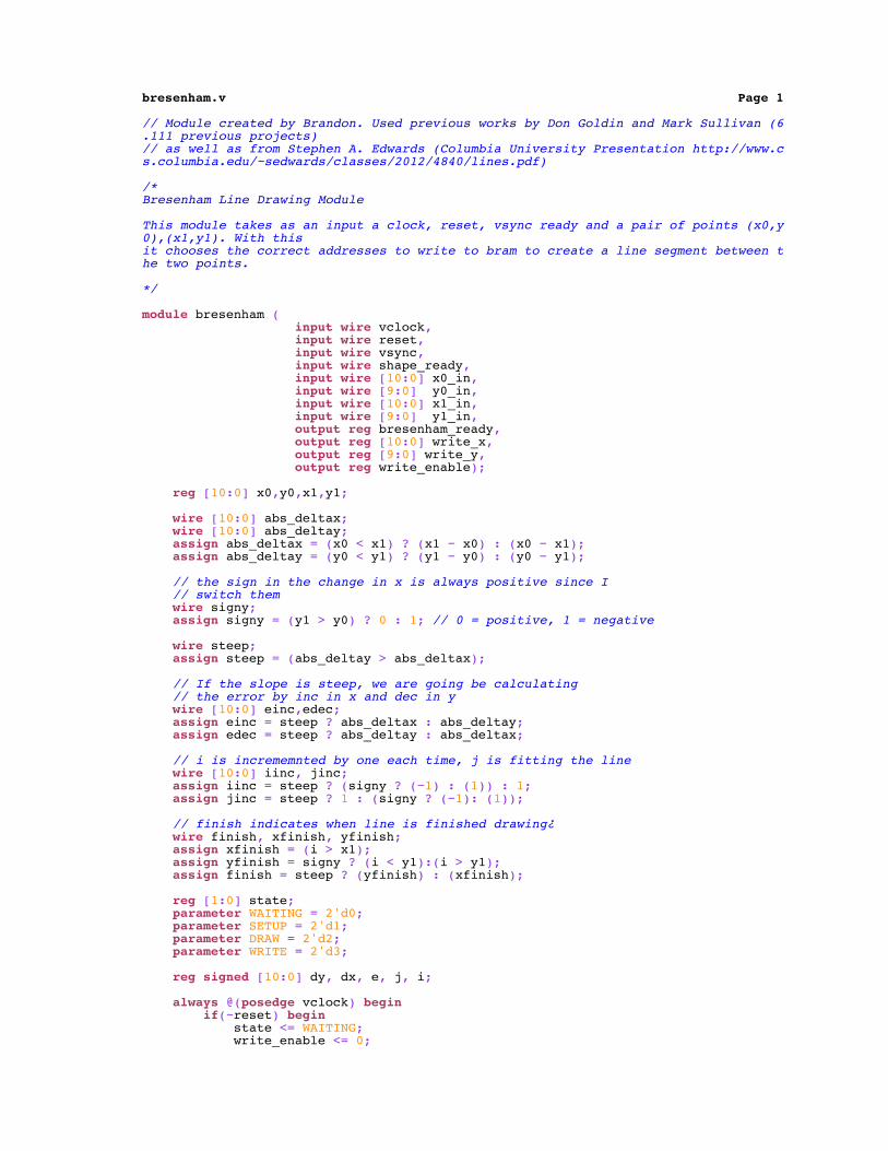
bresenham.v Page 1
// Module created by Brandon. Used previous works by Don Goldin and Mark Sullivan (6.111 previous projects)// as well as from Stephen A. Edwards (Columbia University Presentation http://www.cs.columbia.edu/~sedwards/classes/2012/4840/lines.pdf)
/*Bresenham Line Drawing Module
This module takes as an input a clock, reset, vsync ready and a pair of points (x0,y0),(x1,y1). With thisit chooses the correct addresses to write to bram to create a line segment between the two points.
*/
module bresenham ( input wire vclock, input wire reset, input wire vsync, input wire shape_ready, input wire [10:0] x0_in, input wire [9:0] y0_in, input wire [10:0] x1_in, input wire [9:0] y1_in, output reg bresenham_ready, output reg [10:0] write_x, output reg [9:0] write_y, output reg write_enable);
reg [10:0] x0,y0,x1,y1;
wire [10:0] abs_deltax; wire [10:0] abs_deltay; assign abs_deltax = (x0 < x1) ? (x1 − x0) : (x0 − x1); assign abs_deltay = (y0 < y1) ? (y1 − y0) : (y0 − y1);
// the sign in the change in x is always positive since I // switch them wire signy; assign signy = (y1 > y0) ? 0 : 1; // 0 = positive, 1 = negative
wire steep; assign steep = (abs_deltay > abs_deltax);
// If the slope is steep, we are going be calculating // the error by inc in x and dec in y wire [10:0] einc,edec; assign einc = steep ? abs_deltax : abs_deltay; assign edec = steep ? abs_deltay : abs_deltax;
// i is incrememnted by one each time, j is fitting the line wire [10:0] iinc, jinc; assign iinc = steep ? (signy ? (−1) : (1)) : 1; assign jinc = steep ? 1 : (signy ? (−1): (1));
// finish indicates when line is finished drawing¿ wire finish, xfinish, yfinish; assign xfinish = (i > x1); assign yfinish = signy ? (i < y1):(i > y1); assign finish = steep ? (yfinish) : (xfinish);
reg [1:0] state; parameter WAITING = 2'd0; parameter SETUP = 2'd1; parameter DRAW = 2'd2; parameter WRITE = 2'd3;
reg signed [10:0] dy, dx, e, j, i;
always @(posedge vclock) begin if(~reset) begin state <= WAITING; write_enable <= 0;

bresenham.v Page 2
write_x <= 0; write_y <= 0; bresenham_ready <= 1; end else if(state == WAITING && shape_ready)begin // We are ready to load up the new line if(x0_in > x1_in) begin x0 <= x1_in; y0 <= y1_in; x1 <= x0_in; y1 <= y0_in; end else begin // lets force drawing form left to right // to simplify things x0 <= x0_in; y0 <= y0_in; x1 <= x1_in; y1 <= y1_in; end state <= SETUP; bresenham_ready <= 0; end else if(~vsync) begin // The actual line drawing case(state) SETUP: begin dy <= abs_deltay; dx <= abs_deltax; e <= steep ? (abs_deltax−abs_deltay) : (abs_deltay−abs_deltax); i <= steep ? y0 : x0; j <= steep ? x0 : y0; state <= DRAW; end
DRAW: begin if(finish) begin write_enable <= 0; write_x <= 0; write_y <= 0; bresenham_ready <= 1; state <= WAITING; end else begin //steep drawing write_x <= steep ? j[10:0] : i[10:0]; write_y <= steep ? i[9:0] : j[9:0]; write_enable <= 1; end
if(e >= 0) begin i <= i + iinc; j <= j + jinc; e <= e − edec + einc; end else begin i <= i + iinc; e <= e + einc; end end
WRITE: begin write_enable <= 0; state <= DRAW; end
default: begin state <= WAITING; end endcase end end
endmodule


