Portable Ozone Generator Krishna Keshav Chaudhary Department of Computer and Electronics Engineering KANTIPUR ENGINEERING COLLEGE Kathmandu, Nepal [email protected]Krishna Sapkota Department of Computer and Electronics Engineering KANTIPUR ENGINEERING COLLEGE Kathmandu, Nepal [email protected]Abstract—Ozone gas is now-a-days used for treatment of drinking water, disinfection, and air-purification. What one requires is a small and handy unit to be plugged into mains to get ozonated air at suitable pressure flowing out from a tube. It can then be let into environment or bubbled through water or any other polluted liquid. But the gadget must be completely safe to work with. Ozone generators invariably make use of a discharge tube to which a high electric field is applied so as to break down the oxygen present in the air. This phenomenon occurs at or near a field strength of 25 kV/cm, and the resulting discharge that takes place is known as Corona. The corona has a light bluish glow. It is in this corona field that oxygen becomes ozone (O 3). Ozone generator presented here has a capacity of producing 10 mg/minute of ozone Combined with atmospheric air. This unit can treat five liters of impure water in just two minutes. Complete disinfection of water, in any impure form, is realized with an ozone Content of 4 mg/liter. The discharge tube is supplied air from an air-group, which is built into the unit. The unit produces ozonated air at a pressure head of 15-20 cm of water via its outlet. So, the exit tube can be let into water containers with water up to a level of 10 - 15 cm. Index Terms—Air-purification, Ozonated air, Corona I. I NTRODUCTION Ozone is a colourless to slightly bluish gas which is formed when oxygen is exposed to UV radiation or an electrical charge. The oxygen molecules (O 2 ) split to form ozone molecules (O 3 ). This is a very unstable arrangement and the third oxygen molecule will split off to oxidise the first pollutant with which it comes in contact. The pollutant is destroyed, and oxygen remains. Because of its powerful oxi- dising ability, ozone has been recognised since the early 1900’s as an effective disinfectant, deodorizer and anti-pollutant. It will disinfect air, destroy bad odours, toxic fumes, bacteria, algae, fungi, mould and mildew. It is more widely used commercially in the water and waste-water industries for purification and disinfection purposes than as a disinfectant in the food industry. A Dutch chemist called Van Marum was probably the first person to detect ozone gas sensorially. However, the discovery of ozone was only just mentioned by name decennia later, in a writing of Schonbein that dates to 1840 in the University of Munchen [1]. After 1840, many studies on the disinfection mechanism of ozone followed. The first ozone generator was manufactured in Berlin by Von Siemens. The first technical- scale application of ozone took place in oudshoorn, Nether- lands, in 1893. This ozone installation was thoroughly studies by French scientists [2]. Ozone production did not reach its prior level until after WorldWar II. In 1950, the number of ozone installations that were in use worldwide had only grown to 119. In 1977 this number, had increased to 1043 ozone installations. More than half of the installations were in France. Around 1985, the number of applied ozone installations was estimated > 2000 [1]. Boglarski and Telikicherla (1995) stated that ozone was used as early as 1893 in Europe for drinking water treatment, and today is the most commonly used disinfection process in Europe [3].The major ozone installations in drinking water plants using ozone for disinfection were built in Paris (1897) and Nice (1904), France, and in St. Petersburg, Russia (1910). Today, chlorine is still preferred over ozone for water dis- infection. However, the last decennia the application of ozone applications did start to increase again. This was caused by the discovery of trihalomethanes (THM) as a harmful disinfection byproduct of chlorine disinfection, in 1973. Chlorine is highly carcinogenic because when it comes into Contact with rem- nants of pesticides in our foodstuff (vegetables), it generates halomethanes, which are carcinogenic [8]. Consequentially, scientists started looking for alternative disinfectants. Another problem was an increase in disturbing, difficultly removable organic micropollutants in surface waters. These compounds appeared to be oxidized by ozone faster than by chlorine and chlorine compounds. Furthermore, ozone turned out to deactivate even those microorganisms that develop resistance to disinfectants, such as Cryptosporidium. This project reviews electrically methods of generation of low-concentration ozone for various applications including water treatment. Various membrane and discharge tube suit- able for electrically ozone generation are discussed in terms of the efficiency of ozone yield, material stability against aggressive oxidative environment during ozone generation, as well as costs and power consumption. Ozone is a very powerful oxidant (E=+2.07 V) that can react with numerous organics present in water [4]. Corona discharge is the condition created when a high voltage passes through an air gap. In the case of ozone production, this high voltage transfers energy for the breaking of the O 2 molecule, allowing the formation of a 3-atom oxygen molecule ozone [5]. Ozone has tendency to revert to its original form in about 10 - 20 minutes, in the atmosphere. Therefore, it is necessary in any ozone application to generate ozone as and when required for use since it cannot KEC Conference __________________________________________________________________________________________ 158 KECConference2019, Kantipur Engineering College, Dhapakhel Lalitpur
Transcript
consideration has been represented as life factor in thisstudy. Similarly, the variation in overlay thickness asper design for both configurations has been presentedas thickness factor. The thickness factor ranged from0.82 to 0.95 and the life factor was about 1.56 to 1.57across all the samples. The mean, standard deviationand coefficient of variation of the results are shown inTable II.
TABLE IISUMMARY OF RESULTS
ThicknessFactor
LifeFactor
Mean 0.9 1.56Standard Deviation 0.038 0.005
Coefficient of Variation 4.24% 0.32%
Where,• the Thickness Factor is the ratio of overlay P-401
thickness as per design for parallel taxiway caseto that for central taxiway case, ceteris paribus
• the Life Factor is the ratio of structural pavementlife of runway for parallel taxiway case to thatfor central taxiway case for identical pavement
IV. CONCLUSION
The result discussed above has significance in air-side configuration planning and associated economicanalysis of runway-taxiway system. Beside the knownbenefit of parallel taxiway for runway capacity as itallows significantly lesser runway occupancy time ascompared to central taxiway for each aircraft move-ment, this study discusses additional benefit in termsof greater pavement life and/or economical overlaydesign. However, this could be offset by the ad-ditional land acquisition cost, and construction andmaintenance cost of greater area of parallel taxiwayin comparison to that of the central taxiway. There-fore, airport-specific cost-benefit analysis should beconducted before any airside features planning byconsidering all known costs and benefits.
Moreover, two aircrafts operational in Nepalese do-mestic air transport but not included in FAARFIELDlibrary, namely ATR 72-500 and Xian MA-60, havebeen added in the course of this study. The aircraftcharacteristics can be added to the external XMLlibrary of FAARFIELD as required for any design orevaluation works.
Also, this study was limited to a single fleetmix (similar to the kind commonly encountered inNepalese domestic air transport) and hence, may notfully cover all the possible variations in pavement de-sign and evaluation. Therefore, a more comprehensivestudy with various probable fleet mixes including thatof international airliners should be conducted for acomplete understanding of this subject.
REFERENCES
[1] Airport Pavement Design and Evaluation, AC 150/5320-6F. Washington, DC, USA: Federal Aviation Administration,2016.
[2] Standardized Method for Reporting Airport PavementStrength, AC 150/5335-5. Washington, DC, USA: FederalAviation Administration, 2014.
[3] Standards for Specifying Construction of Airports, AC150/5370-10G. Washington, DC, USA: Federal Aviation Ad-ministration, 2014.
[4] Federal Aviation Administration Rigid and Flexible Itera-tive Elastic Layered Design (FAARFIELD) User Manual(2018).Washington, DC, USA: Federal Aviation Administra-tion, 2016.
[5] ”Aircraft Movement Data of Dhangadhi Airport for 2017 and2018.” Dhangadhi Civil Aviation Office, 2018.
[6] P. Jackson, All the Worlds Aircraft. Surrey: Janes InformationGroup, 2005, pp. 100.
[7] ATR-72 Flight Manual. France: Regional Transport Airplanes,2003.
Abstract—Ozone gas is now-a-days used for treatment ofdrinking water, disinfection, and air-purification. What onerequires is a small and handy unit to be plugged into mainsto get ozonated air at suitable pressure flowing out from a tube.It can then be let into environment or bubbled through wateror any other polluted liquid. But the gadget must be completelysafe to work with. Ozone generators invariably make use of adischarge tube to which a high electric field is applied so asto break down the oxygen present in the air. This phenomenonoccurs at or near a field strength of 25 kV/cm, and the resultingdischarge that takes place is known as Corona. The corona hasa light bluish glow. It is in this corona field that oxygen becomesozone (O3). Ozone generator presented here has a capacity ofproducing 10 mg/minute of ozone Combined with atmosphericair. This unit can treat five liters of impure water in just twominutes. Complete disinfection of water, in any impure form, isrealized with an ozone Content of 4 mg/liter. The discharge tubeis supplied air from an air-group, which is built into the unit.The unit produces ozonated air at a pressure head of 15-20 cmof water via its outlet. So, the exit tube can be let into watercontainers with water up to a level of 10− 15 cm.
Index Terms—Air-purification, Ozonated air, Corona
I. INTRODUCTION
Ozone is a colourless to slightly bluish gas which is formedwhen oxygen is exposed to UV radiation or an electricalcharge. The oxygen molecules (O2) split to form ozonemolecules (O3). This is a very unstable arrangement andthe third oxygen molecule will split off to oxidise the firstpollutant with which it comes in contact. The pollutant isdestroyed, and oxygen remains. Because of its powerful oxi-dising ability, ozone has been recognised since the early 1900’sas an effective disinfectant, deodorizer and anti-pollutant. Itwill disinfect air, destroy bad odours, toxic fumes, bacteria,algae, fungi, mould and mildew. It is more widely usedcommercially in the water and waste-water industries forpurification and disinfection purposes than as a disinfectantin the food industry.
A Dutch chemist called Van Marum was probably the firstperson to detect ozone gas sensorially. However, the discoveryof ozone was only just mentioned by name decennia later, ina writing of Schonbein that dates to 1840 in the Universityof Munchen [1]. After 1840, many studies on the disinfectionmechanism of ozone followed. The first ozone generator wasmanufactured in Berlin by Von Siemens. The first technical-scale application of ozone took place in oudshoorn, Nether-lands, in 1893. This ozone installation was thoroughly studies
by French scientists [2]. Ozone production did not reach itsprior level until after WorldWar II. In 1950, the number ofozone installations that were in use worldwide had only grownto 119. In 1977 this number, had increased to 1043 ozoneinstallations. More than half of the installations were in France.Around 1985, the number of applied ozone installations wasestimated > 2000 [1].
Boglarski and Telikicherla (1995) stated that ozone wasused as early as 1893 in Europe for drinking water treatment,and today is the most commonly used disinfection processin Europe [3].The major ozone installations in drinking waterplants using ozone for disinfection were built in Paris (1897)and Nice (1904), France, and in St. Petersburg, Russia (1910).
Today, chlorine is still preferred over ozone for water dis-infection. However, the last decennia the application of ozoneapplications did start to increase again. This was caused by thediscovery of trihalomethanes (THM) as a harmful disinfectionbyproduct of chlorine disinfection, in 1973. Chlorine is highlycarcinogenic because when it comes into Contact with rem-nants of pesticides in our foodstuff (vegetables), it generateshalomethanes, which are carcinogenic [8]. Consequentially,scientists started looking for alternative disinfectants. Anotherproblem was an increase in disturbing, difficultly removableorganic micropollutants in surface waters. These compoundsappeared to be oxidized by ozone faster than by chlorineand chlorine compounds. Furthermore, ozone turned out todeactivate even those microorganisms that develop resistanceto disinfectants, such as Cryptosporidium.
This project reviews electrically methods of generation oflow-concentration ozone for various applications includingwater treatment. Various membrane and discharge tube suit-able for electrically ozone generation are discussed in termsof the efficiency of ozone yield, material stability againstaggressive oxidative environment during ozone generation,as well as costs and power consumption. Ozone is a verypowerful oxidant (E=+2.07 V) that can react with numerousorganics present in water [4]. Corona discharge is the conditioncreated when a high voltage passes through an air gap. In thecase of ozone production, this high voltage transfers energyfor the breaking of the O2 molecule, allowing the formationof a 3-atom oxygen molecule ozone [5]. Ozone has tendencyto revert to its original form in about 10− 20 minutes, in theatmosphere. Therefore, it is necessary in any ozone applicationto generate ozone as and when required for use since it cannot
be kept stored the way chlorine is stored (in cylinders).The unit is that it is light in weight (less than a kilogram)
and carries a microcontroller based control with automatic andmanual mode, where LCD showing the ozone concentration.It employs a high voltage of over 5 kV at a high frequencyof 15 kHz to 20 kHz, which would not cause a lethal shock.Shock Voltages are not cause a lethal shock. Shock voltagesare not dangerous at these high frequencies, while at 50 Hzthese high voltages are quite dangerous. Commercial ozonegenerators make use of mains 50Hz frequency and are thusvery dangerous while assembling. Extreme care is required tobe exercised by the user while diagnosing any problem withsuch apparatus. Ozone generator at the higher frequencies usedhere is more efficient and silent in its discharge, one can easilyassemble this portable ozone generator in a plastic breadbox(used for storing one full bread), which is all insulated (withno exposed metal parts. The cost of making a simple unit ismuch less than Rs. 2,000.
Different types of ozone generator are available in themarket nowadays which are expensive and portability of thosedevices are quite difficult and are dangerous might cause alethal shock if not careful. Finally, in the context of Nepalwater purification and waste-water treatment in industries aredone through the use chlorine. Also, Nepal is among the leastdeveloped countries in the world, with about one-quarter of itspopulation living below the poverty line. Nepal is facing quitea number of issues, some of these significant challenges arerelated to water pollution, air pollution, sanitation. Regard-ing these issue, Portable Ozone Generator is developed forthe purpose of water purification, waste-water treatment, air-purification, bleaching, vegetable cleaning, mosquito repulsionand many more with the features of portability, lethal shockproof and that falls under affordable price.
II. METHODOLOGY
Ozone generators invariably make use of a discharge tube towhich a high electric field is applied to break down the oxygenpresent in the air. This phenomenon occurs at or near a fieldstrength of 25 kV/cm, and the resulting discharge that takesplace is known as Corona. The corona has a light bluish glow.It is in this corona field that oxygen becomes ozone (O3).
The discharge tube is supplied air from an air-group, whichis built into the unit. The unit produces ozonated air at apressure head of 15-20 cm of water via its outlet. So, the exittube can be let into water containers with water up to a levelof 10-15 cm. Pump works on mains and has a 50Hz vibratorattached to a rubber bellows that provides a pulsating airflowthat provides a pulsating airflow. This air flows through thecylindrical space of discharge tube and discharge tube outletgives ozonated air. The overall mechanism are controlled withthe help of micro-controller (AT mega 32) embedded in it.
The operational framework of portable ozone generator isshown in figure 1. It contains various sub system includingmechanical, electrical and computer. The whole system isdivided into two main parts i.e. mechanical and electronical.
Fig 1: Block Diagram of the System
Electronical System: This section further divided into var-ious sub system. I.e. pulse generator, micro-controller unit,switching unit etc.
Pulse generator section: A simple pulse generator circuitutilized various active and passive component and is designedto generate 1520 KHz pulses. It selects duty cycle of 33%.
Control Unit: As its name implies it is the control unit of thecircuit and is comprise of micro-controller ATmega32, keypad,and temperature sensor unit. This unit control the productionof ozone.
Switching Unit: This unit consist of switching circuit whichis used to switch FBT to generate ozone
Figure 2 describe the flowchart of the system where ’t’represent the temperature and t1, t2 represents the lower andupper threshold temperature for the device.
Discharge tube is constructed using the 20cm long Alu-minium tube of 1cm diameter and Glass tube of 17cm lengthand 1.2cm in diameter. This aluminium tube is blocked on theinside with a small amount of M-seal compound, so that noair can pass directly through its middle hole. Then, holes of2mm diameter are made on the tube at the two ends about3 cm from each end. To provide the discharge gap, a thinwalled glass tube, commonly used as chemistry test tube, isused having an inner diameter about 1.2-1.5 mm greater thanthat of the aluminium tube. Then, the glass tube is cut suchthat it covers the length of the aluminium tube, except forabout 1.5 cm at each end such that the metal tube should beable to go freely in it. Now, the glass tube is rotated over agas burner to soften the ends of the tube and made chamferedon to the metal tube, such that at the edges, the glass tubefits the metal tube with no gap and still the glass tube is ableto slide over the aluminium tube. After the glass tube is sopositioned over the metal tube, the ends of the glass tube aretaped using Teflon tape.
Preparation of the hot electrode: The hot electrode, to whicha voltage greater than 6,000 volts is applied at high frequency,is made by closely wrapping plain aluminium foil around theouter side of the glass tube. The foil is wrapped leaving 1 cmuncovered area on either ends of the tube. The foil is taped fortightness on the outer glass, using cellulose tape, and a piece ofTeflon insulated wire connected to the aluminium foil broughtout. This wire is connected to the EHT lead from the LOT onthe circuit board.
III. RESULTS
Complete disinfection of water, in any impure form, isrealized with an ozone content of 4 mg/litre. Ozone generatorpresented here has a capacity of producing 10 mg/minuteof ozone combined with atmospheric air and can treat fivelitres of impure water in just two minutes.Figure 3 shows theconstructed discharge tube for corona discharge.
Fig 3: Discharge Tube
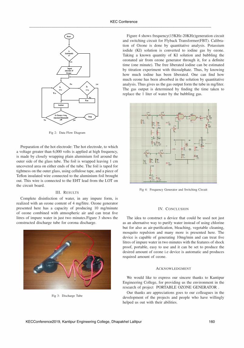
Figure 4 shows frequency(15KHz-20KHz)generation circuitand switching circuit for Flyback Transformer(FBT). Calibra-tion of Ozone is done by quantitative analysis. Potassiumiodide (KI) solution is converted to iodine gas by ozone.Taking a known quantity of KI solution and bubbling theozonated air from ozone generator through it, for a definitetime (one minute). The free liberated iodine can be estimatedby titration experiment with thiosulphate. Thus, by knowinghow much iodine has been liberated. One can find howmuch ozone has been absorbed in the solution by quantitativeanalysis. Thus gives us the gas output form the tube in mg/liter.The gas output is determined by finding the time taken toreplace the 1 liter of water by the bubbling gas.
Fig 4: Frequency Generator and Switching Circuit
IV. CONCLUSION
The idea to construct a device that could be used not justas an alternative way to purify water instead of using chlorinebut for also as air-purification, bleaching, vegetable cleaning,mosquito repulsion and many more is presented here. Thedevice is capable of generating 10mg/min and can treat fivelitres of impure water in two minutes with the features of shockproof, portable, easy to use and it can be set to produce thedesired amount of ozone i.e device is automatic and producesrequired amount of ozone.
ACKNOWLEDGMENT
We would like to express our sincere thanks to KantipurEngineering College, for providing us the environment in theresearch of project PORTABLE OZONE GENERATOR .
Our thanks are appreciations goes to our colleagues in thedevelopment of the projects and people who have willinglyhelped us out with their abilities.
be kept stored the way chlorine is stored (in cylinders).The unit is that it is light in weight (less than a kilogram)
and carries a microcontroller based control with automatic andmanual mode, where LCD showing the ozone concentration.It employs a high voltage of over 5 kV at a high frequencyof 15 kHz to 20 kHz, which would not cause a lethal shock.Shock Voltages are not cause a lethal shock. Shock voltagesare not dangerous at these high frequencies, while at 50 Hzthese high voltages are quite dangerous. Commercial ozonegenerators make use of mains 50Hz frequency and are thusvery dangerous while assembling. Extreme care is required tobe exercised by the user while diagnosing any problem withsuch apparatus. Ozone generator at the higher frequencies usedhere is more efficient and silent in its discharge, one can easilyassemble this portable ozone generator in a plastic breadbox(used for storing one full bread), which is all insulated (withno exposed metal parts. The cost of making a simple unit ismuch less than Rs. 2,000.
Different types of ozone generator are available in themarket nowadays which are expensive and portability of thosedevices are quite difficult and are dangerous might cause alethal shock if not careful. Finally, in the context of Nepalwater purification and waste-water treatment in industries aredone through the use chlorine. Also, Nepal is among the leastdeveloped countries in the world, with about one-quarter of itspopulation living below the poverty line. Nepal is facing quitea number of issues, some of these significant challenges arerelated to water pollution, air pollution, sanitation. Regard-ing these issue, Portable Ozone Generator is developed forthe purpose of water purification, waste-water treatment, air-purification, bleaching, vegetable cleaning, mosquito repulsionand many more with the features of portability, lethal shockproof and that falls under affordable price.
II. METHODOLOGY
Ozone generators invariably make use of a discharge tube towhich a high electric field is applied to break down the oxygenpresent in the air. This phenomenon occurs at or near a fieldstrength of 25 kV/cm, and the resulting discharge that takesplace is known as Corona. The corona has a light bluish glow.It is in this corona field that oxygen becomes ozone (O3).
The discharge tube is supplied air from an air-group, whichis built into the unit. The unit produces ozonated air at apressure head of 15-20 cm of water via its outlet. So, the exittube can be let into water containers with water up to a levelof 10-15 cm. Pump works on mains and has a 50Hz vibratorattached to a rubber bellows that provides a pulsating airflowthat provides a pulsating airflow. This air flows through thecylindrical space of discharge tube and discharge tube outletgives ozonated air. The overall mechanism are controlled withthe help of micro-controller (AT mega 32) embedded in it.
The operational framework of portable ozone generator isshown in figure 1. It contains various sub system includingmechanical, electrical and computer. The whole system isdivided into two main parts i.e. mechanical and electronical.
Fig 1: Block Diagram of the System
Electronical System: This section further divided into var-ious sub system. I.e. pulse generator, micro-controller unit,switching unit etc.
Pulse generator section: A simple pulse generator circuitutilized various active and passive component and is designedto generate 1520 KHz pulses. It selects duty cycle of 33%.
Control Unit: As its name implies it is the control unit of thecircuit and is comprise of micro-controller ATmega32, keypad,and temperature sensor unit. This unit control the productionof ozone.
Switching Unit: This unit consist of switching circuit whichis used to switch FBT to generate ozone
Figure 2 describe the flowchart of the system where ’t’represent the temperature and t1, t2 represents the lower andupper threshold temperature for the device.
Discharge tube is constructed using the 20cm long Alu-minium tube of 1cm diameter and Glass tube of 17cm lengthand 1.2cm in diameter. This aluminium tube is blocked on theinside with a small amount of M-seal compound, so that noair can pass directly through its middle hole. Then, holes of2mm diameter are made on the tube at the two ends about3 cm from each end. To provide the discharge gap, a thinwalled glass tube, commonly used as chemistry test tube, isused having an inner diameter about 1.2-1.5 mm greater thanthat of the aluminium tube. Then, the glass tube is cut suchthat it covers the length of the aluminium tube, except forabout 1.5 cm at each end such that the metal tube should beable to go freely in it. Now, the glass tube is rotated over agas burner to soften the ends of the tube and made chamferedon to the metal tube, such that at the edges, the glass tubefits the metal tube with no gap and still the glass tube is ableto slide over the aluminium tube. After the glass tube is sopositioned over the metal tube, the ends of the glass tube aretaped using Teflon tape.
Preparation of the hot electrode: The hot electrode, to whicha voltage greater than 6,000 volts is applied at high frequency,is made by closely wrapping plain aluminium foil around theouter side of the glass tube. The foil is wrapped leaving 1 cmuncovered area on either ends of the tube. The foil is taped fortightness on the outer glass, using cellulose tape, and a piece ofTeflon insulated wire connected to the aluminium foil broughtout. This wire is connected to the EHT lead from the LOT onthe circuit board.
III. RESULTS
Complete disinfection of water, in any impure form, isrealized with an ozone content of 4 mg/litre. Ozone generatorpresented here has a capacity of producing 10 mg/minuteof ozone combined with atmospheric air and can treat fivelitres of impure water in just two minutes.Figure 3 shows theconstructed discharge tube for corona discharge.
Fig 3: Discharge Tube
Figure 4 shows frequency(15KHz-20KHz)generation circuitand switching circuit for Flyback Transformer(FBT). Calibra-tion of Ozone is done by quantitative analysis. Potassiumiodide (KI) solution is converted to iodine gas by ozone.Taking a known quantity of KI solution and bubbling theozonated air from ozone generator through it, for a definitetime (one minute). The free liberated iodine can be estimatedby titration experiment with thiosulphate. Thus, by knowinghow much iodine has been liberated. One can find howmuch ozone has been absorbed in the solution by quantitativeanalysis. Thus gives us the gas output form the tube in mg/liter.The gas output is determined by finding the time taken toreplace the 1 liter of water by the bubbling gas.
Fig 4: Frequency Generator and Switching Circuit
IV. CONCLUSION
The idea to construct a device that could be used not justas an alternative way to purify water instead of using chlorinebut for also as air-purification, bleaching, vegetable cleaning,mosquito repulsion and many more is presented here. Thedevice is capable of generating 10mg/min and can treat fivelitres of impure water in two minutes with the features of shockproof, portable, easy to use and it can be set to produce thedesired amount of ozone i.e device is automatic and producesrequired amount of ozone.
ACKNOWLEDGMENT
We would like to express our sincere thanks to KantipurEngineering College, for providing us the environment in theresearch of project PORTABLE OZONE GENERATOR .
Our thanks are appreciations goes to our colleagues in thedevelopment of the projects and people who have willinglyhelped us out with their abilities.
[1] A. R. LEEDS, “Lines of discovery in the history of ozone,” Annals ofthe New York Academy of Sciences, vol. 1, no. 1, pp. 363–426, 1879.
[2] R. Rice and A. Netzer, Handbook of ozone technology and applications,ser. Handbook of Ozone Technology and Applications. Ann ArborScience, 1982, no. v. 1.
[3] N. P. Cheremisinoff, Handbook of water and wastewater treatmenttechnologies. Butterworth-Heinemann, 2001.
[4] K. Rakness, Ozone in Drinking Water Treatment: Process Design, Oper-ation, and Optimization. American Water Works Association, 2011.
[5] R. Feng, Power Measurement of Corona Discharge for Ozone Generation.Faculty of Graduate Studies, University of Western Ontario, 1996.
[6] A. F, B. Langlais, D. Reckhow, and D. Brink, Ozone in Water Treatment:Application and Engineering, ser. Cooperative research report. Taylor& Francis, 1991.
[7] Z. Buntat, Ozone Generation Using Electrical Discharges. VDMPublishing, 2010.
[8] C. O’Donnell, B. Tiwari, P. Cullen, and R. Rice, Ozone in Food Process-ing. Wiley, 2012.
[9] Z. Wang, K. Cen, J. Zhou, and J. Fan, Simultaneous Multi-PollutantsRemoval in Flue Gas by Ozone, ser. Advanced Topics in Science andTechnology in China. Springer Berlin Heidelberg, 2014.
Abstract— Engineering structures is an important aspect of human civilization and manual analysis of structure often deviates from actual value, so there is a need to use Finite Element Method technique for analyzing those structures. Thus, this paper presents FEM based codes developed in MATLAB programming which targets the analysis of 2D linear, elastic-isotropic structure. This program lists the results of displacement, stress-strain, reaction forces and plots the deformed shaped due to applied forces. Since the software is solitary only on truss analysis, it computes faster compare to other market software like ANSYS, COMSOL etc.
Keywords—linear structure, finite element method, MATLAB programming
I. INTRODUCTION Considering various aspects of the complexities, the solutions which are baffling and sticking to the conventional method will eventually leads to trivial solution. Therefore, to make the calculation precise, numerical analysis is done. Among various forms of numerical analysis for solving problems of engineering and mathematical physics, Finite Element Method (FEM) is the most preferred one. Thus, it is very necessary to create a program-based on FEM, to meet today’s digitalized world. Thus, this developed software aims to able a common platform for all the linear elastic structure. Also due to of its simplicity, person having faint knowledge of structures and FEM can easily use this program. Different Subject matter that required for completion of this project are.
A. Finite Element Method Finite Element Method is a numerical method in which a complex domain defining a continuum is discretized into various simple geometric shape called finite elements. This process results in a set of simultaneous algebraic equations and the solution is obtained upon computing these equations. The material properties and governing equations considered over the finite elements are expressed in terms of unknown parameter at elemental nodes where different elements of the structure are connected [1]. The simple equations that model these finite elements are then assembled into a larger system of equations that models the entire problem [2]. Here, in this research, the principle of direct method of analysis was used. The basic principle used here is the sum of force acting on the element must be zero. If F1 and F2 are two force acting on the element, then;
F1 + F2 = 0 Also, the relation between force and displacement is given by: F = K*u, where, F= Force, K= stiffness, u=displacement. So, if the two elements of similar material have displacement as u1 and u2 on applying force F1 and F2 then; F1 = k (u1 – u2) and F2 = k (u2 – u1) where k is the stiffness of material. Stiffness of material for truss is given by the product of modulus of elasticity with area divided by the elemental length [3]. That is
𝑘𝑘 = 𝐸𝐸𝐸𝐸𝑙𝑙 [ 1 −1
−1 1 ] Hence, rearranging, the above equations becomes: