PORTLAND CEMENT CONCRETE Civil and construction engineers are directly responsible for the quality con- trol of portland cement concrete and the proportions of the components used in it. The quality of the concrete is governed by the chemical composition of the portland cement, hydration and development of the microstructure, ad- mixtures, and aggregate characteristics. The quality is strongly affected by placement, consolidation, and curing, as well. How a concrete structure performs throughout its service life is largely af- fected by the methods of mixing, transporting, placing, and curing the concrete in the field. In fact, the ingredients of a “good” concrete may be the same as those of a “bad” concrete. The difference, however, is often the expertise of the engineer and technicians who are handling the concrete during construction. Because of the advances made in concrete technology in the past few decades, concrete can be used in many more applications. Civil and con- struction engineers should be aware of the alternatives to conventional con- crete, such as lightweight concrete, high-strength concrete, polymer concrete, fiber-reinforced concrete, and roller-compacted concrete. Before using these alternatives to conventional concrete, the engineer needs to study them, and their costs, in detail. This chapter covers basic principles of conventional portland cement concrete, its proportioning, mixing and handling, curing, and testing. Alternatives to conventional concrete that increase the applica- tions and improve the performance of concrete are also introduced. Proportioning of Concrete Mixes The properties of concrete depend on the mix proportions and the placing and curing methods. Designers generally specify or assume a certain strength or modulus of elasticity of the concrete when determining structural dimensions. 7.1 7
Transcript
PORTLAND CEMENT
CONCRETE
Civil and construction engineers are directly responsible for the quality con-trol of portland cement concrete and the proportions of the components usedin it. The quality of the concrete is governed by the chemical composition ofthe portland cement, hydration and development of the microstructure, ad-mixtures, and aggregate characteristics. The quality is strongly affected byplacement, consolidation, and curing, as well.
How a concrete structure performs throughout its service life is largely af-fected by the methods of mixing, transporting, placing, and curing the concretein the field. In fact, the ingredients of a “good” concrete may be the same asthose of a “bad” concrete. The difference, however, is often the expertise of theengineer and technicians who are handling the concrete during construction.
Because of the advances made in concrete technology in the past fewdecades, concrete can be used in many more applications. Civil and con-struction engineers should be aware of the alternatives to conventional con-crete, such as lightweight concrete, high-strength concrete, polymer concrete,fiber-reinforced concrete, and roller-compacted concrete. Before using thesealternatives to conventional concrete, the engineer needs to study them, andtheir costs, in detail. This chapter covers basic principles of conventionalportland cement concrete, its proportioning, mixing and handling, curing,and testing. Alternatives to conventional concrete that increase the applica-tions and improve the performance of concrete are also introduced.
Proportioning of Concrete Mixes
The properties of concrete depend on the mix proportions and the placing andcuring methods. Designers generally specify or assume a certain strength ormodulus of elasticity of the concrete when determining structural dimensions.
7.1
7MamCh07v3.qxd 8/3/05 7:16 PM Page 235
236 Chapter 7 Portland Cement Concrete
The materials engineer is responsible for assuring that the concrete is properlyproportioned, mixed, placed, and cured so to have the properties specified bythe designer.
The proportioning of the concrete mix affects its properties in both theplastic and solid states. During the plastic state, the materials engineer isconcerned with the workability and finishing characteristics of the concrete.Properties of the hardened concrete important to the materials engineer arethe strength, modulus of elasticity, durability, and porosity. Strength is gen-erally the controlling design factor. Unless otherwise specified, concretestrength refers to the average compressive strength of three tests. Eachtest is the average result of two cylinderstested in compression after curing for 28 days.
The PCA specifies three qualities required of properly proportionedconcrete mixtures (Kosmatka et al. 2002):
1. acceptable workability of freshly mixed concrete2. durability, strength, and uniform appearance of hardened concrete3. economy
In order to achieve these characteristics, the materials engineer must de-termine the proportions of cement, water, fine and coarse aggregates, and theuse of admixtures. Several mix design methods have been developed overthe years, ranging from an arbitrary volume method (1:2:3 cement: sand:coarse aggregate) to the weight and absolute volume methods prescribed bythe American Concrete Institute’s Committee 211. The weight method pro-vides relatively simple techniques for estimating mix proportions, using anassumed or known unit weight of concrete. The absolute volume methoduses the specific gravity of each ingredient to calculate the unit volume eachwill occupy in a unit volume of concrete. The absolute volume method ismore accurate than the weight method. The mix design process for theweight and absolute volume methods differs only in how the amount of fineaggregates is determined.
7.1.1 ■ Basic Steps for Weight and Absolute Volume Methods
The basic steps required for determining mix design proportions for bothweight and absolute volume methods are as follows (Kosmatka et al. 2002):
1. Evaluate strength requirements.2. Determine the water–cementitious materials ratio required.3. Evaluate coarse aggregate requirements.
■ maximum aggregate size of the coarse aggregate■ quantity of the coarse aggregate
4. Determine air entrainment requirements.5. Evaluate workability requirements of the plastic concrete.6. Estimate the water content requirements of the mix.7. Determine cementing materials content and type needed.
0.15-m * 0.30-m 16-in. * 12-in.2f¿c
MamCh07v3.qxd 8/3/05 7:16 PM Page 236
Section 7.1 Proportioning of Concrete Mixes 237
8. Evaluate the need and application rate of admixtures.9. Evaluate fine aggregate requirements.
10. Determine moisture corrections.11. Make and test trial mixes.
Most concrete supply companies have a wealth of experience about howtheir materials perform in a variety of applications. This experience, ac-companied with reliable test data on the relationship between strength andwater–cementitious materials ratio, is the most dependable method for se-lecting mix proportions. However, understanding the basic principles ofmixture design and the proper selection of materials and mixture character-istics is as important as the actual calculation. Therefore, the PCA procedureprovides guidelines and can be adjusted to match the experience obtainedfrom local conditions. The PCA mix design steps are discussed next.
1. Strength Requirements Variations in materials, and batching and mixing ofconcrete results in deviations in the strength of the concrete produced by aplant. Generally, the structural design engineer does not consider this variabil-ity when determining the size of the structural members. If the materials engi-neer provides a material with an average strength equal to the strength specifiedby the designer, then half of the concrete will be weaker than the specifiedstrength. Obviously, this is undesirable. To compensate for the variance in con-crete strength, the materials engineer designs the concrete to have an averagestrength greater than the strength specified by the structural engineer.
In order to compute the strength requirements for concrete mix design,three quantities must be known:
1. the specified compressive strength 2. the variability or standard deviation s of the concrete3. the allowable risk of making concrete with an unacceptable strength
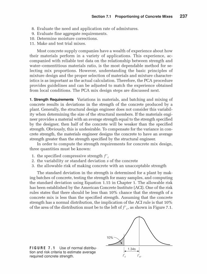
The standard deviation in the strength is determined for a plant by mak-ing batches of concrete, testing the strength for many samples, and computingthe standard deviation using Equation 1.15 in Chapter 1. The allowable riskhas been established by the American Concrete Institute (ACI). One of the riskrules states that there should be less than 10% chance that the strength of aconcrete mix is less than the specified strength. Assuming that the concretestrength has a normal distribution, the implication of the ACI rule is that 10%of the area of the distribution must be to the left of as shown in Figure 7.1.f¿c,
f¿c
10%
f'c f'cr
1.34sF I G U R E 7 . 1 Use of normal distribu-tion and risk criteria to estimate averagerequired concrete strength.
MamCh07v3.qxd 8/3/05 7:16 PM Page 237
238 Chapter 7 Portland Cement Concrete
Using a table of standard z values for a normal distribution curve, we can de-termine that 90% of the area under the curve will be to the right of if theaverage strength is 1.34 standard deviations from In other words, the re-quired average strength for this criterion can be calculated as
(7.1)
where
average compressive strength, MPa or psicompressive strength, MPa or psideviation, MPa or psi
For mixes with a large standard deviation in strength, the ACI has an-other risk criterion that requires
(7.2)
The required average compressive strength is determined as the largervalue obtained from Equations 7.1 and 7.2.
Equation 7.2 is valid for SI units only. If U.S. customary units are used,and s are recorded in psi and the constant 3.45 in Equation 7.2 should
be changed to 500.The standard deviation should be determined from at least 30 strength
tests. If the standard deviation is computed from 15 to 30 samples, then thestandard deviation is multiplied by the following factor, F, to determine themodified standard deviation s¿.
f¿cr, f¿c,
f¿cr
f¿cr = f¿c + 2.33s - 3.45
s = standardf¿c = specified
f¿cr = required
f¿cr = f¿c + 1.34s
f¿cr
f¿c.f¿c
Number of Modification Tests Factor F
15 1.1620 1.0825 1.03
30 or more 1.00
Specified Required Average Compressive Strength Compressive Strength
Linear interpolation is used for an intermediate number of tests, and is used in place of s in Equations 7.1 and 7.2.
If fewer than 15 tests are available, the following adjustments are madeto the specified strength, instead of using Equations 7.1 and 7.2:
s¿
MamCh07v3.qxd 8/3/05 7:16 PM Page 238
Section 7.1 Proportioning of Concrete Mixes 239
These estimates are very conservative and should not be used for large pro-jects, since the concrete will be overdesigned and, therefore, not economical.
Sample Problem 7.1
The design engineer specifies a concrete strength of 31.0 MPa (4500 psi). Determinethe required average compressive strength for
a. a new plant for which s is unknownb. a plant for which (520 psi) for 17 test resultsc. a plant with extensive history of producing concrete with (350 psi)d. a plant with extensive history of producing concrete with (550 psi)
Solution
a. (5700 psi)
b. Need to interpolate modification factor:
Multiply standard deviation by the modification factor
Determine maximum from Equations 7.1 and 7.2
c. Determine maximum from Equations 7.1 and 7.2
d. Determine maximum from Equations 7.1 and 7.2
2. Water–Cementitious Materials Ratio Requirements The next step is to deter-mine the water–cementitious materials ratio needed to produce the required
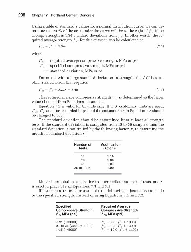
F I G U R E 7 . 2 Exampletrial mixture or field datastrength curves.
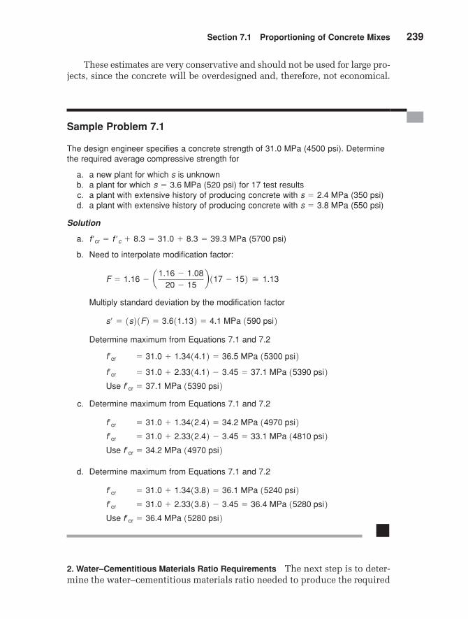
strength. Historical records are used to plot a strength-versus–water–cemen-titious materials ratio curve, such as that seen in Figure 7.2. If historical dataare not available, three trial batches are made at different water–cementi-tious materials ratios to establish a curve similar to Figure 7.2. Table 7.1 canbe used for estimating the water–cementitious materials ratios for the trialmixes when no other data are available. The required average compressivestrength is used with the strength versus water–cementitious materials rela-tionship to determine the water–cementitious materials ratio required forthe strength requirements of the project.
T A B L E 7 . 1 Typical Relationship between Water–Cementitious Materials Ratio and Compressive Strength of Concrete*
*American Concrete Institute (ACI 211.1 and ACI 211.3)**Strength is based on cylinders moist-cured 28 days in accordance with
ASTM C31 (AASHTO T23). Relationship assumes nominal maximum sizeof aggregate about 19 to 25 mm ( to 1 in.).3�4
MamCh07v3.qxd 8/3/05 7:16 PM Page 240
Section 7.1 Proportioning of Concrete Mixes 241
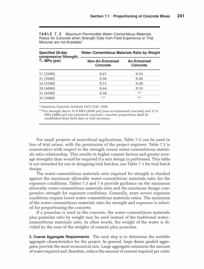
T A B L E 7 . 2 Maximum Permissible Water–Cementitious Materials Ratios for Concrete when Strength Data from Field Experience or TrialMixtures are not Available*
Specified 28-day Water–Cementitious Materials Ratio by Weightcompressive Strength,
*American Concrete Institute (ACI 318), 1999.**For strength above 31.0 MPa (4500 psi) (non-air-entrained concrete) and 27.6
MPa (4000 psi) (air-entrained concrete), concrete proportions shall beestablished from field data or trial mixtures.
f cœ ,
For small projects of noncritical applications, Table 7.2 can be used inlieu of trial mixes, with the permission of the project engineer. Table 7.2 isconservative with respect to the strength versus water–cementitious materi-als ratio relationship. This results in higher cement factors and greater aver-age strengths than would be required if a mix design is performed. This tableis not intended for use in designing trial batches; use Table 7.1 for trial batchdesign.
The water–cementitious materials ratio required for strength is checkedagainst the maximum allowable water–cementitious materials ratio for theexposure conditions. Tables 7.3 and 7.4 provide guidance on the maximumallowable water–cementitious materials ratio and the minimum design com-pressive strength for exposure conditions. Generally, more severe exposureconditions require lower water–cementitious materials ratios. The minimumof the water–cementitious materials ratio for strength and exposure is select-ed for proportioning the concrete.
If a pozzolan is used in the concrete, the water–cementitious materialsplus pozzolan ratio by weight may be used instead of the traditional water–cementitious materials ratio. In other words, the weight of the water is di-vided by the sum of the weights of cement plus pozzolan.
3. Coarse Aggregate Requirements The next step is to determine the suitableaggregate characteristics for the project. In general, large dense graded aggre-gates provide the most economical mix. Large aggregates minimize the amountof water required and, therefore, reduce the amount of cement required per cubic
MamCh07v3.qxd 8/3/05 7:16 PM Page 241
242 Chapter 7 Portland Cement Concrete
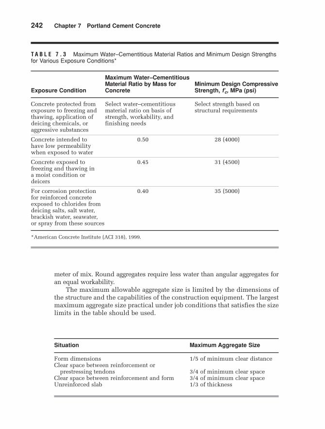
T A B L E 7 . 3 Maximum Water–Cementitious Material Ratios and Minimum Design Strengthsfor Various Exposure Conditions*
Maximum Water–Cementitious Material Ratio by Mass for Minimum Design Compressive
Exposure Condition Concrete Strength, MPa (psi)
Concrete protected from Select water–cementitious Select strength based on exposure to freezing and material ratio on basis of structural requirementsthawing, application of strength, workability, and deicing chemicals, or finishing needsaggressive substances
Concrete intended to 0.50 28 (4000)have low permeability when exposed to water
Concrete exposed to 0.45 31 (4500)freezing and thawing in a moist condition or deicers
For corrosion protection 0.40 35 (5000)for reinforced concrete exposed to chlorides from deicing salts, salt water, brackish water, seawater, or spray from these sources
*American Concrete Institute (ACI 318), 1999.
f cœ ,
Situation Maximum Aggregate Size
Form dimensions 1/5 of minimum clear distanceClear space between reinforcement or
prestressing tendons 3/4 of minimum clear spaceClear space between reinforcement and form 3/4 of minimum clear spaceUnreinforced slab 1/3 of thickness
meter of mix. Round aggregates require less water than angular aggregates foran equal workability.
The maximum allowable aggregate size is limited by the dimensions ofthe structure and the capabilities of the construction equipment. The largestmaximum aggregate size practical under job conditions that satisfies the sizelimits in the table should be used.
MamCh07v3.qxd 8/3/05 7:16 PM Page 242
Section 7.1 Proportioning of Concrete Mixes 243
T A B L E 7 . 4 Requirements for Concrete Exposed to Sulfates in Soil or Water*
Maximum Minimum Water-Soluble Sulfate Water– Design Sulfate ( ) ( ) in Cementitious Compressive
Sulfate in Soil, Percent Water, Material Ratio Strength, Exposure by Weight** ppm** Cement Type*** by Weight MPa (psi)
Negligible Less than 0.10 Less than 150 No special type required — —
Moderate**** 0.10–0.20 150–1500 II, MS, IP(MS), IS(MS), P(MS),
I(PM)(MS), I(SM)(MS) 0.50 28 (4000)
Severe 0.20–2.00 1500–10,000 V, HS 0.45 31 (4500)
Very Severe Over 2.00 Over 10,000 V, HS 0.40 35 (5000)
*Adopted from American Concrete Institute (ACI 318), 1999.**Tested in accordance with the Method for Determining the Quantity of Soluble Sulfate in Solid (Soil
and Rock) and Water Samples, Bureau of Reclamation, Denver, 1977.***Cement Types II and V are in ASTM C150 (AASHTO M85), Types MS and HS in ASTM C1157, and
the remaining types are in ASTM C595 (AASHTO M240). Pozzolans or slags that have been determined by test or severe record to improve sulfate resistance may also be used.
****Sea water.
f cœ ,
SO4SO4
Sample Problem 7.2
A structure is to be built with concrete with a minimum dimension of 0.2 m, minimumspace between rebars of 40 mm, and minimum cover over rebars of 40 mm. Two typesof aggregate are locally available, with maximum sizes of 19 mm and 25 mm, respec-tively. If both types of aggregate have essentially the same cost, which one is more suit-able for this structure?
Solution
Therefore, both sizes satisfy the dimension requirements. However, 25 mm aggre-gate is more suitable, because it will produce more economical concrete mix.
25 mm 6 13/42140 mm2 rebar cover.
25 mm 6 13/42140 mm2 rebar spacing.
25 mm 6 11/521200 mm2 minimum dimensions.
MamCh07v3.qxd 8/3/05 7:16 PM Page 243
244 Chapter 7 Portland Cement Concrete
The gradation of the fine aggregates is defined by the fineness modulus.The desirable fineness modulus depends on the coarse aggregate size andthe quantity of cement paste. A low fineness modulus is desired for mixeswith low cement content to promote workability.
Once the fineness modulus of the fine aggregate and the maximumsize of the coarse aggregate are determined, the volume of coarse aggregateper unit volume of concrete is determined using Table 7.5. For example,if the fineness modulus of the fine aggregate is 2.60 and the maximum ag-gregate size is 25 mm (1 in.), the coarse aggregate will have a volume of
of concrete. Table 7.5 is based on the unit weight of ag-gregates in a dry-rodded condition (ASTM C29). The values given arebased on experience in producing an average degree of workability. Thevolume of coarse aggregate can be increased by 10% when less workabil-ity is required, such as in pavement construction. The volume of coarseaggregate should be reduced by 10% to increase workability, for exampleto allow placement by pumping.
4. Air Entrainment Requirements Next, the need for air entrainment is evaluat-ed. Air entrainment is required whenever concrete is exposed to freeze–thawconditions and deicing salts. Air entrainment is also used for workability insome situations. The amount of air required varies based on exposure conditions
0.69 m3/m3 1yd3/yd32
T A B L E 7 . 5 Bulk Volume of Coarse Aggregate per Unit Volume of Concrete*
Nominal Maximum Bulk Volume of Dry-Rodded Coarse Aggregate Size of Aggregate, Per Unit Volume of Concrete for Different mm (in.) Fineness Moduli of Fine Aggregate**
*American Concrete Institute (ACI 211.1).**Bulk volumes are based on aggregates in a dry-rodded condition as described
in ASTM C29 (AASHTO T19).
11 1�22
13�4211�22
MamCh07v3.qxd 8/3/05 7:16 PM Page 244
Section 7.1 Proportioning of Concrete Mixes 245
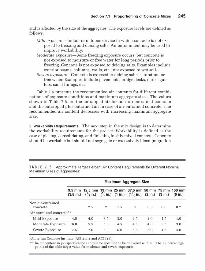
and is affected by the size of the aggregates. The exposure levels are defined asfollows:
Mild exposure—Indoor or outdoor service in which concrete is not ex-posed to freezing and deicing salts. Air entrainment may be used toimprove workability.
Moderate exposure—Some freezing exposure occurs, but concrete isnot exposed to moisture or free water for long periods prior tofreezing. Concrete is not exposed to deicing salts. Examples includeexterior beams, columns, walls, etc., not exposed to wet soil.
Severe exposure—Concrete is exposed to deicing salts, saturation, orfree water. Examples include pavements, bridge decks, curbs, gut-ters, canal linings, etc.
Table 7.6 presents the recommended air contents for different combi-nations of exposure conditions and maximum aggregate sizes. The valuesshown in Table 7.6 are the entrapped air for non–air-entrained concreteand the entrapped plus entrained air in case of air-entrained concrete. Therecommended air content decreases with increasing maximum aggregatesize.
5. Workability Requirements The next step in the mix design is to determinethe workability requirements for the project. Workability is defined as theease of placing, consolidating, and finishing freshly mixed concrete. Concreteshould be workable but should not segregate or excessively bleed (migration
T A B L E 7 . 6 Approximate Target Percent Air Content Requirements for Different NominalMaximum Sizes of Aggregates*
Maximum Aggregate Size
9.5 mm 12.5 mm 19 mm 25 mm 37.5 mm 50 mm 75 mm 150 mm (3/8 in.) ( ) ( ) (1 in.) ( ) (2 in.) (3 in.) (6 in.)
*American Concrete Institute (ACI 211.1 and ACI 318).**The air content in job specifications should be specified to be delivered within to percentage
points of the table target value for moderate and severe exposures.+2-1
11�2 in.3�4 in.1�2 in.
MamCh07v3.qxd 8/3/05 7:16 PM Page 245
246 Chapter 7 Portland Cement Concrete
F I G U R E 7 . 3 Slump test apparatus.
of water to the top surface of concrete). The slump test (Figure 7.3) is an in-dicator of workability when evaluating similar mixtures. This test consistsof filling a truncated cone with concrete, removing the cone, then measur-ing the distance the concrete slumps (ASTM C143). The slump is increasedby adding water, air entrainer, water reducer, superplasticizer, or by usinground aggregates. Table 7.7 provides recommendations for the slump ofconcrete used in different types of projects. For batch adjustments, slump
T A B L E 7 . 7 Recommended Slumps for Various Types of Construction*
Slump, mm (in.)
Concrete Construction Maximum** Minimum
Reinforced foundation walls and footings 75 (3) 25 (1)
Plain footings, caissons, and substructure walls 75 (3) 25 (1)
Beams and reinforced walls 100 (4) 25 (1)
Building columns 100 (4) 25 (1)
Pavements and slabs 75 (3) 25 (1)
Mass concrete 75 (3) 25 (1)
*American Concrete Institute (ACI 211.1).**May be increased 25 mm (1 in.) for consolidation by hand methods such as
rodding and spading. Plasticizers can safely provide higher slumps.
MamCh07v3.qxd 8/3/05 7:16 PM Page 246
Section 7.1 Proportioning of Concrete Mixes 247
increases about 25 mm (1in.) for each 6 kg of water added (10 lb percubic yard) of concrete.
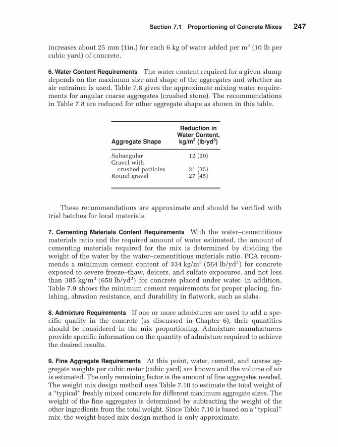
6. Water Content Requirements The water content required for a given slumpdepends on the maximum size and shape of the aggregates and whether anair entrainer is used. Table 7.8 gives the approximate mixing water require-ments for angular coarse aggregates (crushed stone). The recommendationsin Table 7.8 are reduced for other aggregate shape as shown in this table.
per m3
Reduction in Water Content,
Aggregate Shape kg/m3 (lb/yd3)
Subangular 12 (20)Gravel with
crushed particles 21 (35)Round gravel 27 (45)
These recommendations are approximate and should be verified withtrial batches for local materials.
7. Cementing Materials Content Requirements With the water–cementitiousmaterials ratio and the required amount of water estimated, the amount ofcementing materials required for the mix is determined by dividing theweight of the water by the water–cementitious materials ratio. PCA recom-mends a minimum cement content of for concreteexposed to severe freeze–thaw, deicers, and sulfate exposures, and not lessthan for concrete placed under water. In addition,Table 7.9 shows the minimum cement requirements for proper placing, fin-ishing, abrasion resistance, and durability in flatwork, such as slabs.
8. Admixture Requirements If one or more admixtures are used to add a spe-cific quality in the concrete (as discussed in Chapter 6), their quantitiesshould be considered in the mix proportioning. Admixture manufacturersprovide specific information on the quantity of admixture required to achievethe desired results.
9. Fine Aggregate Requirements At this point, water, cement, and coarse ag-gregate weights per cubic meter (cubic yard) are known and the volume of airis estimated. The only remaining factor is the amount of fine aggregates needed.The weight mix design method uses Table 7.10 to estimate the total weight ofa “typical” freshly mixed concrete for different maximum aggregate sizes. Theweight of the fine aggregates is determined by subtracting the weight of theother ingredients from the total weight. Since Table 7.10 is based on a “typical”mix, the weight-based mix design method is only approximate.
385 kg/m3 1650 lb/yd32334 kg/m3 1564 lb/yd32
MamCh07v3.qxd 8/3/05 7:16 PM Page 247
TA
BL
E 7
.8A
ppro
xim
ate
Mix
ing
Wat
er in
kg/
m3
(lb/y
d3 )fo
r D
iffer
ent
Slu
mps
and
Nom
inal
Max
imum
Agg
rega
te S
izes
*
Max
imu
m A
gg
reg
ate
Siz
e in
mm
(in
.)**
Slu
mp
, m
m (
in.)
9.5
(3/8
)12
.5 (
)19
()
25 (
1)37
.5 (
)50
(2)
***
75 (
3)**
*15
0 (6
)***
Non
-air
-en
trai
ned
con
cret
e
25 t
o 50
20
7 (3
50)
199
(335
)19
0 (3
15)
179
(300
)16
6 (2
75)
154
(260
)13
0 (2
20)
113
(190
)(1
to
2)75
to
100
228
(385
)21
6 (3
65)
205
(340
)19
3 (3
25)
181
(300
)16
9 (2
85)
145
(245
)12
4 (2
10)
(3 t
o 4)
150
to 1
75
243
(410
)22
8 (3
85)
216
(360
)20
2 (3
40)
190
(315
)17
8 (3
00)
160
(270
)—
(6 t
o 7)
Air
-en
trai
ned
con
cret
e
25 t
o 50
18
1 (3
05)
175
(295
)16
8 (2
80)
160
(270
)15
0 (2
50)
142
(240
)12
2 (2
05)
107
(180
)(1
to
2)75
to
100
202
(340
)19
3 (3
25)
184
(305
)17
5 (2
95)
165
(275
)15
7 (2
65)
133
(225
)11
9 (2
00)
(3 t
o 4)
150
to 1
75
216
(365
)20
5 (3
45)
197
(325
)18
4 (3
10)
174
(290
)16
6 (2
80)
154
(260
)—
(6 t
o 7)
*Am
eric
an C
oncr
ete
Inst
itu
te (
AC
I 21
1.1
and
AC
I 31
8).
**T
hes
e qu
anti
ties
of
mix
ing
wat
er a
re f
or u
se i
n c
omp
uti
ng
cem
enti
tiou
s m
ater
ial
con
ten
ts f
or t
rial
bat
ches
. Th
ey a
re m
axim
um
s fo
rre
ason
ably
wel
l-sh
aped
an
gula
r co
arse
agg
rega
tes
grad
ed w
ith
in l
imit
s of
acc
epte
d s
pec
ific
atio
ns.
***T
he
slu
mp
val
ues
for
con
cret
e co
nta
inin
g ag
greg
ates
lar
ger
than
37.
5 m
m
are
base
d o
n s
lum
p t
ests
mad
e af
ter
rem
oval
of
par
ticl
es l
arge
r th
an 3
7.5
mm
by
wet
scr
een
ing.
11 1 � 2 in
.211 � 23 � 4
1 � 2
MamCh07v3.qxd 8/3/05 7:16 PM Page 248
Section 7.1 Proportioning of Concrete Mixes 249
T A B L E 7 . 9 Minimum Requirements of Cementing Materials for Concrete Used in Flatwork*
Maximum Size of Aggregate Cementing Materials, mm (in.) kg/m3 (lb/yd3)**
37.5 280 (470)25.0 (1) 310 (520)19.0 320 (540)
12.5 350 (590)9.5 (3/8) 360 (610)
*American Concrete Institute (ACI 302).**Cementing materials quantities may need to be
greater for severe exposure. For example, for deicer exposures, concrete should contain atleast 335 kg/m3 (564 lb/yd3) of cementing materials.
11�2213�42111�22
T A B L E 7 . 1 0 Estimate of Weight of Freshly MixedConcrete
Maximum Non Air Entrained Air Entrained Aggregate Concrete Concrete Size, mm (in.) kg/m3 (lb/yd3) kg/m3 (lb/y3)
In the absolute volume method of mix design, the component weightand the specific gravity are used to determine the volumes of the water,coarse aggregate, and cement. These volumes, along with the volume of theair, are subtracted from a unit volume of concrete to determine the volume
MamCh07v3.qxd 8/3/05 7:16 PM Page 249
250 Chapter 7 Portland Cement Concrete
of the fine aggregate required. The volume of the fine aggregate is then con-verted to a weight using the unit weight. Generally, the bulk SSD specificgravity of aggregates is used for the weight–volume conversions of both fineand coarse aggregates.
10. Moisture Corrections Mix designs assume that water used to hydratethe cement is the free water in excess of the moisture content of the aggre-gates at the SSD condition (absorption), as discussed in Chapter 5. There-fore, the final step in the mix design process is to adjust the weight ofwater and aggregates to account for the existing moisture content of the ag-gregates. If the moisture content of the aggregates is more than the SSDmoisture content, the weight of mixing water is reduced by an amountequal to the free weight of the moisture on the aggregates. Similarly, if themoisture content is below the SSD moisture content, the mixing watermust be increased.
11. Trial Mixes After computing the required amount of each ingredient, atrial batch is mixed to check the mix design. Three
cylinders are made, cured for 28 days, and tested for com-pressive strength. In addition, the air content and slump of fresh concreteare measured. If the slump, air content, or compressive strength does notmeet the requirements, the mixture is adjusted and other trial mixes aremade until the design requirements are satisfied.
Additional trial batches could be made by slightly varying the materialquantities in order to determine the most workable and economical mix.
Sample Problem 7.3
You are working on a concrete mix design that requires each cubic yard of concrete tohave a 0.43 water–cementitious materials ratio, of dry gravel, ofwater, and 4% air content. The available gravel has a specific gravity of amoisture content of 2.3% and absorption of 4.5%. The available sand has a specificgravity of a moisture content of 2.2% and absorption of 1.7%. Air entraineris to be included using the manufacturers specification of 0.1 fl. oz / 1% air / 100 lb ce-ment.
For each cubic yard of concrete needed on the job, calculate the weight of cement,moist gravel, moist sand, and water that should be added to the batch. Summarize andtotal the mix design when finished.
Design a concrete mix for the following conditions and constraints using the absolutevolume method:
Design EnvironmentBridge pier exposed to freezing and subjected to deicing chemicalsRequired design (3500 psi)Minimum (12 in.)Minimum space between (2 in.)Minimum cover over (1.5 in.)Standard deviation of compressive strength of 2.4 MPa (350 psi) is expected
(more than 30 samples)Only air entrainer is allowed
T A B L E 7 . 1 2 Relative Components of Concrete for Small Jobs, by Volume*
Air-Entrained Concrete Non-Air-Entrained ConcreteMaximum Size of Coarse Aggregate Wet Fine Wet Coarse Wet Fine Wet Coarse mm (in.) Cement Aggregate Aggregate Water Cement Aggregate Aggregate Water
*Portland Cement Association, 2002.The combined volume is approximately 2/3 of the sum of the original bulk volumes.
111�2213�4211�22
7.1.2 ■ Mixing Concrete for Small Jobs
The mix design process applies to large jobs. For small jobs, for which alarge design effort is not economical (e.g., jobs requiring less than one cubicmeter of concrete), Tables 7.11 and 7.12 can be used as a guide. The valuesin these tables may need to be adjusted to obtain a workable mix, using the
T A B L E 7 . 1 1 Relative Components of Concrete for Small Jobs, by Weight*
Air-Entrained Concrete Non-Air-Entrained ConcreteMaximum Size of Coarse Aggregate Wet Fine Wet Coarse Wet Fine Wet Coarse mm (in.) Cement Aggregate Aggregate** Water Cement Aggregate Aggregate** Water
*Portland Cement Association, 2002.**If crushed stone is used, decrease coarse aggregate by 50 kg and increase fine aggregate by 50 kg for
each cubic meter of concrete (or decrease coarse aggregate by 3 lb and increase fine aggregateby 3 lb for each cubic foot of concrete).
111�2213�4211�22
MamCh07v3.qxd 8/3/05 7:16 PM Page 254
Section 7.1 Proportioning of Concrete Mixes 255
locally available aggregates. Recommendations related to exposure condi-tions discussed earlier should be followed.
Tables 7.11 and 7.12 are used for proportioning concrete mixes byweight and volume, respectively. The tables provide ratios of components,with a sum of one unit. Therefore, the required total weight or volume of theconcrete mix can be multiplied by the given ratios to obtain the weight orvolume of each component. Note that for proportioning by volume, the com-bined volume is approximately two-thirds of the sum of the original bulkvolumes of the components, since water and fine materials fill the voids be-tween coarse materials.
Sample Problem 7.5
Determine the required weights of ingredients to make a 3500-lb batch of non-air-en-trained concrete mix with a maximum gravel size of 1/2 in.
SolutionFrom Table 7.11:
Weight of Weight of wet fine Weight of wet coarse Weight of
Sample Problem 7.6
Determine the required volumes of ingredients to make a batch of air-entrainedconcrete mix with a maximum gravel size of 19 mm.
SolutionSum of the original bulk volumes of the FromTable 7.12:
Volume of Volume of wet fine Volume of wet coarse Volume of water = 0.75 * 0.080 = 0.06 m3
The proper batching, mixing, and handling of fresh concrete are importantprerequisites for strong and durable concrete structures. Next we will dis-cuss the basic steps and precautions to be followed in mixing and handlingfresh concrete (Mehta and Monteiro 1993; American Concrete Institute1982; American Concrete Institute 1983).
Batching is measuring and introducing the concrete ingredients into themixer. Batching by weight is more accurate than batching by volume, sinceweight batching avoids the problem created by bulking of damp sand. Waterand liquid admixtures, however, can be measured accurately either byweight or volume. On the other hand, batching by volume is commonly usedwith continuous mixers and when hand mixing.
Concrete should be mixed thoroughly, either in a mixer or by hand,until it becomes uniform in appearance. Hand mixing is usually limited tosmall jobs or situations in which mechanical mixers are not available. Me-chanical mixers include on-site mixers and central mixers in ready-mixplants. The capacity of these mixers varies from to ( to
). Mixers also vary in type, such as tilting, nontilting, and pan-typemixers. Most of the mixers are batch mixers, although some mixers arecontinuous.
Mixing time and number of revolutions vary with the size and type ofthe mixer. Specifications usually require a minimum of 1 minute of mixingfor stationary mixers of up to of capacity, with an increaseof 15 seconds for each additional of capacity. Mixers are usuallycharged with 10% of the water, followed by uniform additions of solids and80% of the water. Finally, the remainder of the water is added to the mixer.
7.2.1 ■ Ready-Mixed Concrete
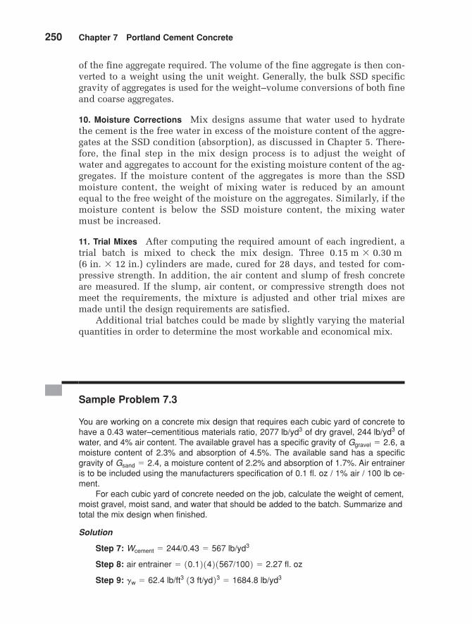
Ready-mixed concrete is mixed in a central plant, and delivered to the jobsite in mixing trucks ready for placing (Figure 7.4). Three mixing methodscan be used for ready mixed concrete:
1. Central-mixed concrete is mixed completely in a stationary mixer anddelivered in an agitator truck (2 rpm to 6 rpm).
2. Shrink-mixed concrete is partially mixed in a stationary mixer andcompleted in a mixer truck (4 rpm to 16 rpm).
3. Truck-mixed concrete is mixed completely in a mixer truck (4 rpm to16 rpm).
Truck manufacturers usually specify the speed of rotation for theirequipment. Also, specifications limit the number of revolutions in a truck
0.75 m30.75 m3 11 yd32
12 yd32 yd39 m31.5 m3
7.2
MamCh07v3.qxd 8/3/05 7:16 PM Page 256
Section 7.2 Mixing, Placing, and Handling Fresh Concrete 257
F I G U R E 7 . 4 Concrete ready mix plant.
mixer in order to avoid segregation. Furthermore, the concrete should bedischarged at the job site within 90 minutes from the start of mixing, even ifretarders are used (ASTM C94).
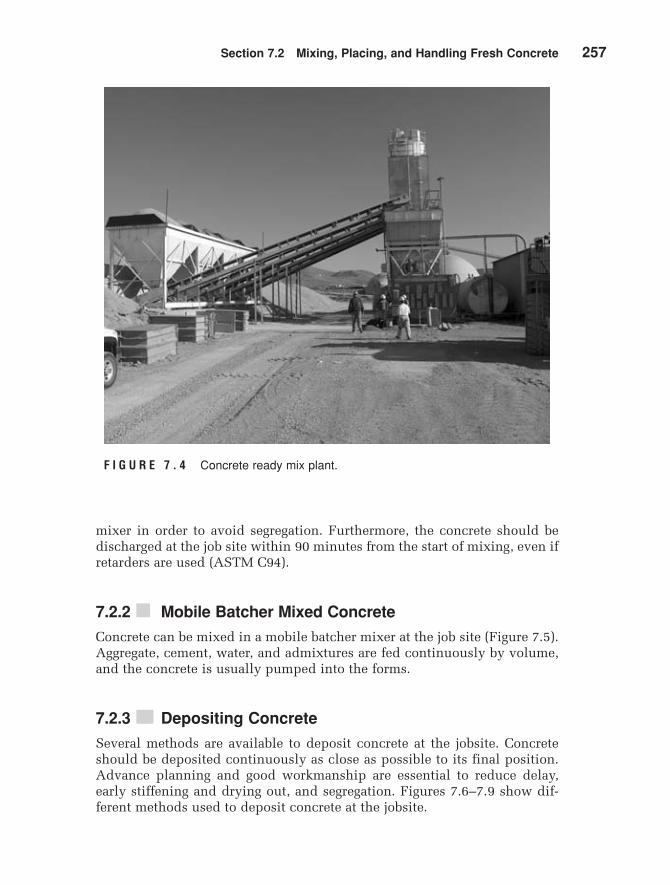
7.2.2 ■ Mobile Batcher Mixed Concrete
Concrete can be mixed in a mobile batcher mixer at the job site (Figure 7.5).Aggregate, cement, water, and admixtures are fed continuously by volume,and the concrete is usually pumped into the forms.
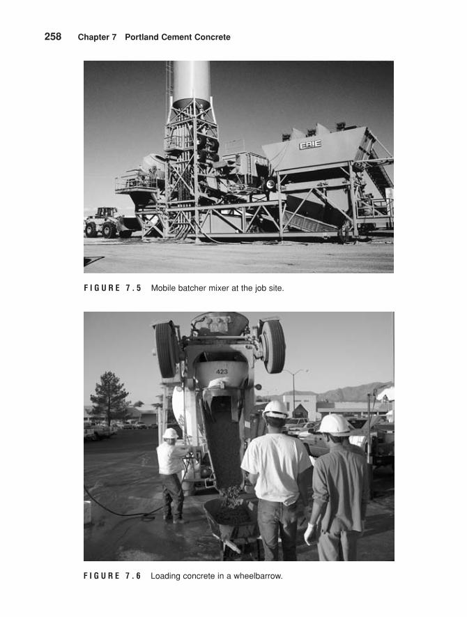
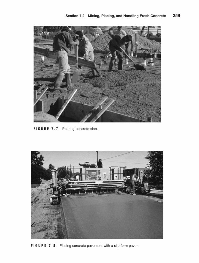
7.2.3 ■■ Depositing Concrete
Several methods are available to deposit concrete at the jobsite. Concreteshould be deposited continuously as close as possible to its final position.Advance planning and good workmanship are essential to reduce delay,early stiffening and drying out, and segregation. Figures 7.6–7.9 show dif-ferent methods used to deposit concrete at the jobsite.
MamCh07v3.qxd 8/3/05 7:16 PM Page 257
258 Chapter 7 Portland Cement Concrete
F I G U R E 7 . 6 Loading concrete in a wheelbarrow.
F I G U R E 7 . 5 Mobile batcher mixer at the job site.
MamCh07v3.qxd 8/3/05 7:16 PM Page 258
Section 7.2 Mixing, Placing, and Handling Fresh Concrete 259
F I G U R E 7 . 7 Pouring concrete slab.
F I G U R E 7 . 8 Placing concrete pavement with a slip-form paver.
MamCh07v3.qxd 8/3/05 7:16 PM Page 259
260 Chapter 7 Portland Cement Concrete
F I G U R E 7 . 9 Depositing concrete using a 2-1/2 cubic yardbucket.
7.2.4 ■■ Pumped Concrete
Pumped concrete is frequently used for large construction projects. Specialpumps deliver the concrete directly into the forms (see Figure 7.10). Carefulattention must be exercised to ensure well-mixed concrete with properworkability. The slump should be between 40 mm to 100 mm (1-1/2 in. to 4 in.)before pumping. During pumping, the slump decreases by about 12 mm to25 mm (1/2 in. to 1 in.), due to partial compaction. Blockage could happenduring pumping, due to either the escape of water through the voids in themix or due to friction if fines content is too high (Neville 1981).
7.2.5 ■■ Vibration of Concrete
Quality concrete requires thorough consolidation to reduce the entrappedair in the mix. On small jobs, consolidation can be accomplished manuallyby ramming and tamping the concrete. For large jobs, vibrators are used toconsolidate the concrete. Several types of vibrators are available, depending
MamCh07v3.qxd 8/3/05 7:16 PM Page 260
Section 7.2 Mixing, Placing, and Handling Fresh Concrete 261
F I G U R E 7 . 1 0 Pumping concrete in a retaining wall.
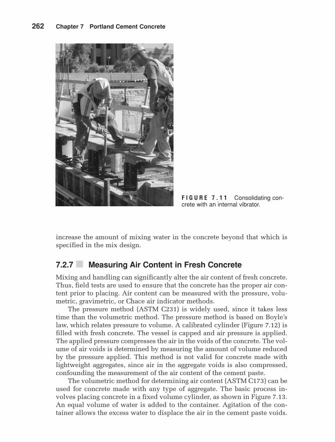
on the application. Internal vibrators are the most common type used onconstruction projects (see Figure 7.11). These consist of an eccentric weighthoused in a spud. The weight is rotated at high speed to produce vibration.The spud is slowly lowered into and through the entire layer of concrete,penetrating into the underlying layer if it is still plastic. The spud is left inplace for 5 seconds to 2 minutes, depending on the type of vibrator and theconsistency of the concrete. The operator judges the total vibration timerequired. Over-vibration causes segregation as the mortar migrates to thesurface.
Several specialty types of vibrators are used in the production of precastconcrete. These include external vibrators, vibrating tables, surface vibra-tors, electric hammers, and vibratory rollers (Neville 1981).
7.2.6 ■■ Pitfalls and Precautions for Mixing Water
Since the water–cementitious materials ratio plays an important role in con-crete quality, the water content must be carefully controlled in the field.Water should not be added to the concrete during transportation. Crewsfrequently want to increase the amount of water in order to improve work-ability. If water is added, the hardened concrete will suffer serious loss inquality and strength. The engineer in the field must prevent any attempt to
MamCh07v3.qxd 8/3/05 7:16 PM Page 261
262 Chapter 7 Portland Cement Concrete
increase the amount of mixing water in the concrete beyond that which isspecified in the mix design.
7.2.7 ■ Measuring Air Content in Fresh Concrete
Mixing and handling can significantly alter the air content of fresh concrete.Thus, field tests are used to ensure that the concrete has the proper air con-tent prior to placing. Air content can be measured with the pressure, volu-metric, gravimetric, or Chace air indicator methods.
The pressure method (ASTM C231) is widely used, since it takes lesstime than the volumetric method. The pressure method is based on Boyle’slaw, which relates pressure to volume. A calibrated cylinder (Figure 7.12) isfilled with fresh concrete. The vessel is capped and air pressure is applied.The applied pressure compresses the air in the voids of the concrete. The vol-ume of air voids is determined by measuring the amount of volume reducedby the pressure applied. This method is not valid for concrete made withlightweight aggregates, since air in the aggregate voids is also compressed,confounding the measurement of the air content of the cement paste.
The volumetric method for determining air content (ASTM C173) can beused for concrete made with any type of aggregate. The basic process in-volves placing concrete in a fixed volume cylinder, as shown in Figure 7.13.An equal volume of water is added to the container. Agitation of the con-tainer allows the excess water to displace the air in the cement paste voids.
F I G U R E 7 . 1 1 Consolidating con-crete with an internal vibrator.
MamCh07v3.qxd 8/3/05 7:16 PM Page 262
Section 7.2 Mixing, Placing, and Handling Fresh Concrete 263
Bowl
Pressure gauge
Air bleeder valve
Air chamber
Clamping device
Extension tubing for calibration checks
Main air valve
Pump
Petcock APetcock B
F I G U R E 7 . 1 2 Pressure method apparatus for determining airvoids in fresh concrete – Type B Meter (ASTM C231). (CopyrightASTM. Reprinted with permission.)
12
0
3456789
Watertight screw cap
Graduated necklined with glass ortransparant plastic
Flanges withgasket and clamps
Topsection
Measuringbowl
F I G U R E 7 . 1 3 Volumetric method (Roll-A-Meter) apparatus for determining air voids infresh concrete (ASTM C173). (Copyright ASTM.Reprinted with permission.)
The water level in the container falls as the air rises to the top of the con-tainer. Thus, the volume of air in the cement paste is directly measured. Theaccuracy of the method depends on agitating the sample enough to removeall the air from it.
The gravimetric method (ASTM C138) compares the unit weight offreshly mixed concrete with the theoretical maximum unit weight of themix. The theoretical unit weight is computed from the mix proportions and
MamCh07v3.qxd 8/3/05 7:16 PM Page 263
264 Chapter 7 Portland Cement Concrete
the specific gravity of each ingredient. This method requires very accuratespecific gravity measurements, and thus is more suited to the laboratoryrather than the field.
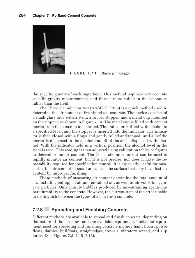
The Chace air indicator test (AASHTO T199) is a quick method used todetermine the air content of freshly mixed concrete. The device consists ofa small glass tube with a stem, a rubber stopper, and a metal cup mountedon the stopper, as shown in Figure 7.14. The metal cup is filled with cementmortar from the concrete to be tested. The indicator is filled with alcohol toa specified level, and the stopper is inserted into the indicator. The indica-tor is then closed with a finger and gently rolled and tapped until all of themortar is dispersed in the alcohol and all of the air is displaced with alco-hol. With the indicator held in a vertical position, the alcohol level in thestem is read. This reading is then adjusted using calibration tables or figuresto determine the air content. The Chace air indicator test can be used torapidly monitor air content, but it is not precise, nor does it have the re-peatability required for specification control. It is especially useful for mea-suring the air content of small areas near the surface that may have lost aircontent by improper finishing.
These methods of measuring air content determine the total amount ofair, including entrapped air and entrained air, as well as air voids in aggre-gate particles. Only minute bubbles produced by air-entraining agents im-part durability to the concrete. However, the current state of the art is unableto distinguish between the types of air in fresh concrete.
7.2.8 ■■ Spreading and Finishing Concrete
Different methods are available to spread and finish concrete, depending onthe nature of the structure and the available equipment. Tools and equip-ment used for spreading and finishing concrete include hand floats, powerfloats, darbies, bullfloats, straightedges, trowels, vibratory screed, and slipforms. (See Figures 7.8, 7.15–7.18).
F I G U R E 7 . 1 4 Chace air indicator.
MamCh07v3.qxd 8/3/05 7:16 PM Page 264
Section 7.2 Mixing, Placing, and Handling Fresh Concrete 265
F I G U R E 7 . 1 5 Spreading concrete with a straightedge.
F I G U R E 7 . 1 6 Finishing concrete with a straightedge.
MamCh07v3.qxd 8/3/05 7:16 PM Page 265
266 Chapter 7 Portland Cement Concrete
F I G U R E 7 . 1 7 Finishing concrete with a power float.
F I G U R E 7 . 1 8 Finishing concrete with a laser level.
MamCh07v3.qxd 8/3/05 7:16 PM Page 266
Section 7.3 Curing Concrete 267
In air after 7
In air after 3
In air entire time
Moist-cured entire time
150
03 7
Age, days180
Com
pre
ssiv
e st
reng
th, %
of 2
8-d
aym
oist
-cur
ed c
oncr
ete
28 90
125
100
75
50
25
F I G U R E 7 . 1 9 Compressive strengthof concrete at different ages and curinglevels.
Curing Concrete
Curing is the process of maintaining satisfactory moisture content and tem-perature in the concrete for a definite period of time. Hydration of cement isa long-term process and requires water and proper temperature. Therefore,curing allows continued hydration and, consequently, continued gains inconcrete strength. In fact, once curing stops, the concrete dries out, and thestrength gain stops, as indicated in Figure 7.19. If the concrete is not curedand is allowed to dry in air, it will gain only about 50% of the strength ofcontinuously cured concrete. If concrete is cured for only three days, it willreach about 60% of the strength of continuously cured concrete; if it is curedfor seven days, it will reach 80% of the strength of continuously cured con-crete. If curing stops for some time and then resumes again, the strength gainwill also stop and reactivate.
Increasing temperature increases the rate of hydration and, consequently,the rate of strength development. Temperatures below 10°C (50°F) are unfa-vorable for hydration and should be avoided, if possible, especially at earlyages.
Although concrete of high strength may not be needed for a particularstructure, strength is usually emphasized and controlled since it is an indica-tion of the concrete quality. Thus, proper curing not only increases strength,but also provides other desirable properties such as durability, water tight-ness, abrasion resistance, volume stability, resistance to freeze and thaw, andresistance to deicing chemicals.
Curing should start after the final set of the cement. If concrete is notcured after setting, concrete will shrink, causing cracks. Drying shrinkagecan be prevented if ample water is provided for a long period of time. An ex-ample of improper curing would be a concrete floor built directly over the
7.3
MamCh07v3.qxd 8/3/05 7:16 PM Page 267
268 Chapter 7 Portland Cement Concrete
subgrade, not cured at the surface, with the moisture in the soil curing itfrom the bottom. In this case the concrete slab may curl due to the relativedifference in shrinkage.
Curing can be performed by any of the following methods:
1. maintaining the presence of water in the concrete during early ages.Methods to maintain the water pressure include pounding or immer-sion, spraying or fogging, and wet coverings.
2. preventing loss of mixing water from the concrete by sealing the surface.Methods to prevent water loss include impervious papers or plasticsheets, membrane-forming compounds, and leaving the forms in place.
3. accelerating the strength gain by supplying heat and additional mois-ture to the concrete. Accelerated curing methods include steam curing,insulating blankets or covers, and various heating techniques.
Note that preventing loss of mixing water from the concrete by sealingthe surface is not as effective as maintaining the presence of water in theconcrete during early ages. The choice of the specific curing method or com-bination of methods depends on the availability of curing materials, size andshape of the structure, in-place versus plant production, economics, andaesthetics (Kosmatka et al. 2002; American Concrete Institute 1986a).
7.3.1 ■■ Ponding or Immersion
Ponding involves covering the exposed surface of the concrete structurewith water. Ponding can be achieved by forming earth dikes around the con-crete surface to retain water. This method is suitable for flat surfaces such asfloors and pavements, especially for small jobs. The method requires inten-sive labor and supervision. Immersion is used to cure test specimens in thelaboratory, as well as other concrete members, as appropriate.
7.3.2 ■■ Spraying or Fogging
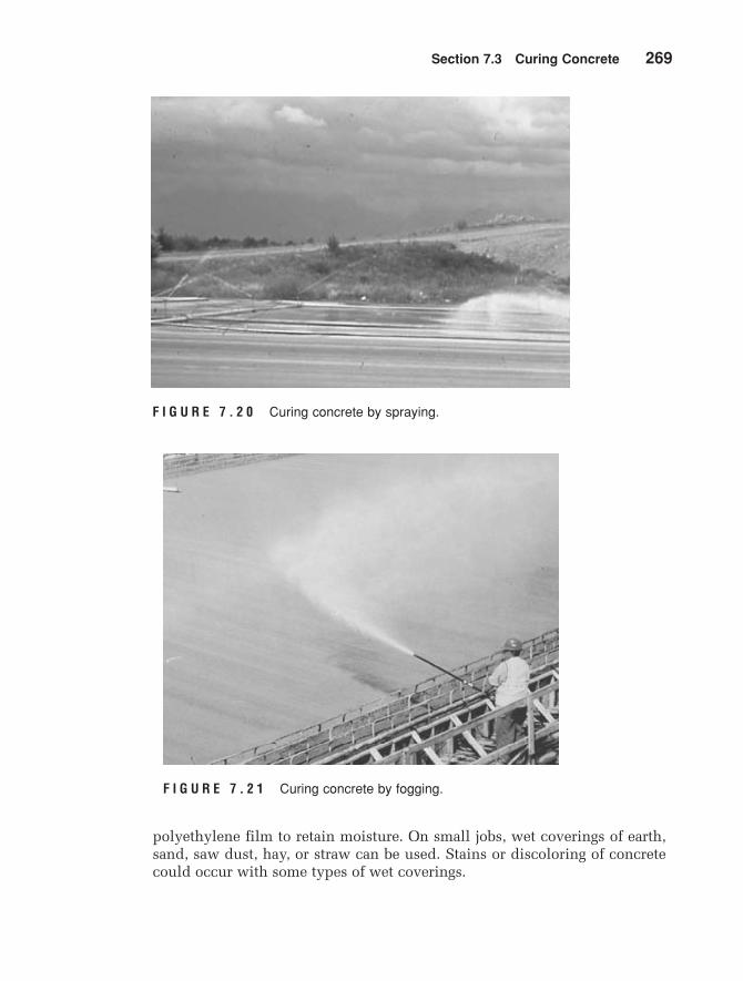
A system of nozzles or sprayers can be used to provide continuous sprayingor fogging (see Figures 7.20 and 7.21). This method requires a large amountof water and could be expensive. It is most suitable in high temperature andlow humidity environments. Commercial test laboratories generally have acontrolled temperature and humidity booth for curing specimens.
7.3.3 ■■ Wet Coverings
Moisture-retaining fabric coverings saturated with water, such as burlap, cot-ton mats, and rugs are used in many applications (see Figure 7.22). The fab-ric can be kept wet, either by periodic watering or covering the fabric with
MamCh07v3.qxd 8/3/05 7:16 PM Page 268
Section 7.3 Curing Concrete 269
F I G U R E 7 . 2 1 Curing concrete by fogging.
F I G U R E 7 . 2 0 Curing concrete by spraying.
polyethylene film to retain moisture. On small jobs, wet coverings of earth,sand, saw dust, hay, or straw can be used. Stains or discoloring of concretecould occur with some types of wet coverings.
MamCh07v3.qxd 8/3/05 7:16 PM Page 269
270 Chapter 7 Portland Cement Concrete
7.3.4 ■■ Impervious Papers or Plastic Sheets
Evaporation of moisture from concrete can be reduced using impervious pa-pers, such as kraft papers, or plastic sheets, such as polyethylene film (seeFigures 7.23 and 7.24). Impervious papers are suitable for horizontal surfaces
F I G U R E 7 . 2 2 Curing concrete by wet covering.
F I G U R E 7 . 2 3 Curing concrete with impervious fabrics.
MamCh07v3.qxd 8/3/05 7:16 PM Page 270
Section 7.3 Curing Concrete 271
and simply shaped concrete structures, while plastic sheets are effective andeasily applied to various shapes. Periodic watering is not required when im-pervious papers or plastic sheets are used. Discoloration, however, canoccur on the concrete surface.
7.3.5 ■■ Membrane-Forming Compounds
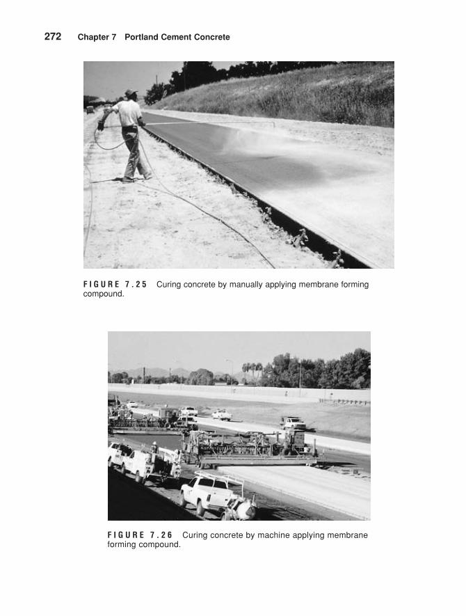
Various types of liquid membrane-forming compounds can be applied to theconcrete surface to reduce or retard moisture loss. These can be used to curefresh concrete, as well as to hardened concrete, after removal of forms orafter moist curing. Curing compounds can be applied by hand or by usingspray equipment (see Figures 7.25 and 7.26). Either one coat or two coats(applied perpendicular to each other) are used. Normally, the concrete sur-face should be damp when the curing compound is applied. Curing com-pounds should not be used when subsequent concrete layers are to beplaced, since the compound hinders the bond between successive layers.Also, some compounds affect the bond between the concrete surface andpaint.
F I G U R E 7 . 2 4 Curing concrete with plastic sheets.
MamCh07v3.qxd 8/3/05 7:16 PM Page 271
272 Chapter 7 Portland Cement Concrete
F I G U R E 7 . 2 5 Curing concrete by manually applying membrane forming compound.
F I G U R E 7 . 2 6 Curing concrete by machine applying membraneforming compound.
MamCh07v3.qxd 8/3/05 7:16 PM Page 272
Section 7.3 Curing Concrete 273
7.3.6 ■■ Forms Left in Place
Loss of moisture can be reduced by leaving the forms in place as long aspractical, provided that the top concrete exposed surface is kept wet. If woodforms are used, the forms should also be kept wet. After removing the forms,another curing method can be used.
7.3.7 ■■ Steam Curing
Steam curing is used when early strength gain in concrete is required or ad-ditional heat is needed during cold weather. Steam curing can be attainedeither with or without pressure. Steam at atmospheric pressure is used forenclosed cast-in-place structures and large precast members. High-pressuresteam in autoclaves can be used at small manufactured plants.
7.3.8 ■■ Insulating Blankets or Covers
When the temperature falls below freezing, concrete should be insulatedusing layers of dry, porous material such as hay or straw. Insulating blanketsmanufactured of fiberglass, cellulose fibers, sponge rubber, mineral wool, vinylfoam, or open-cell polyurethane foam can be used to insulate formwork.Moisture proof commercial blankets can also be used.
7.3.9 ■■ Electrical, Hot Oil, and Infrared Curing
Precast concrete sections can be cured using electrical, oil, or infrared cur-ing techniques. Electrical curing includes electrically heated steel forms,and electrically heated blankets. Reinforcing steel can be used as a heat-ing element, and concrete can be used as the electrical conductor. Steelforms can also be heated by circulating hot oil around the outside of thestructure. Infrared rays have been used for concrete curing on a limitedbasis.
7.3.10 ■■ Curing Period
The curing period should be as long as is practical. The minimum time de-pends on several factors, such as type of cement, mixture proportions, re-quired strength, ambient weather, size and shape of the structure, futureexposure conditions, and method of curing. For most concrete structures thecuring period at temperatures above 5°C (40°F) should be a minimum ofseven days or until 70% of specified compressive or flexure strength is at-tained. The curing period can be reduced to three days if high early strengthconcrete is used and the temperature is above 10°C (50°F).
MamCh07v3.qxd 8/3/05 7:16 PM Page 273
274 Chapter 7 Portland Cement Concrete
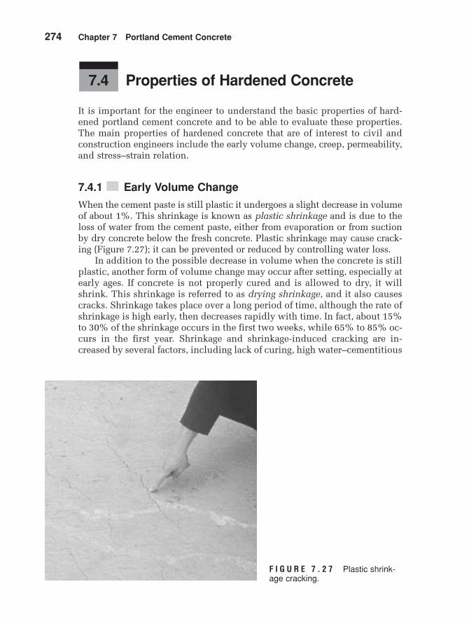
F I G U R E 7 . 2 7 Plastic shrink-age cracking.
Properties of Hardened Concrete
It is important for the engineer to understand the basic properties of hard-ened portland cement concrete and to be able to evaluate these properties.The main properties of hardened concrete that are of interest to civil andconstruction engineers include the early volume change, creep, permeability,and stress–strain relation.
7.4.1 ■■ Early Volume Change
When the cement paste is still plastic it undergoes a slight decrease in volumeof about 1%. This shrinkage is known as plastic shrinkage and is due to theloss of water from the cement paste, either from evaporation or from suctionby dry concrete below the fresh concrete. Plastic shrinkage may cause crack-ing (Figure 7.27); it can be prevented or reduced by controlling water loss.
In addition to the possible decrease in volume when the concrete is stillplastic, another form of volume change may occur after setting, especially atearly ages. If concrete is not properly cured and is allowed to dry, it willshrink. This shrinkage is referred to as drying shrinkage, and it also causescracks. Shrinkage takes place over a long period of time, although the rate ofshrinkage is high early, then decreases rapidly with time. In fact, about 15%to 30% of the shrinkage occurs in the first two weeks, while 65% to 85% oc-curs in the first year. Shrinkage and shrinkage-induced cracking are in-creased by several factors, including lack of curing, high water–cementitious
7.4
MamCh07v3.qxd 8/3/05 7:16 PM Page 274
Section 7.4 Properties of Hardened Concrete 275
materials ratio, high cement content, low coarse aggregate content, existenceof steel reinforcement, and aging. On the other hand, if concrete is curedcontinuously in water after setting, concrete will swell very slightly due tothe absorption of water. Since swelling, if it happens, is very small, it doesnot cause significant problems. Swelling is accompanied by a slight increasein weight (Neville 1981).
How much drying shrinkage occurs depends on the size and shape ofthe concrete structure. Also, nonuniform shrinkage could happen due to thenonuniform loss of water. This may happen in mass concrete structures,where more water is lost at the surface than at the interior. In cases such asthis, cracks may develop at the surface. In other cases, curling might devel-op due to the nonuniform curing throughout the structure and, consequently,nonuniform shrinkage.
7.4.2 ■■ Creep Properties
Creep is defined as the gradual increase in strain, with time, under sustainedload. Creep of concrete is a long-term process, and it takes place over manyyears. Although the amount of creep in concrete is relatively small, it couldaffect the performance of structures. The effect of creep varies with the typeof structure. In simply supported reinforced concrete beams, creep increas-es the deflection and, therefore, increases the stress in the steel. In rein-forced concrete columns, creep results in a gradual transfer of load from theconcrete to the steel. Creep also could result in losing some of the prestressin prestressed concrete structures, although the use of high-tensile stresssteel reduces this effect. Rheological models, discussed in Chapter 1, havebeen used to analyze the creep response of concrete (Neville 1981).
7.4.3 ■■ Permeability
Permeability is an important factor that largely affects the durability ofhardened concrete. Permeable concrete allows water and chemicals to pen-etrate, which, in turn, reduces the resistance of the concrete structure to frost,alkali–aggregate reactivity, and other chemical attacks. Water that permeatesinto reinforced concrete causes corrosion of steel rebars. Furthermore, im-pervious concrete is a prerequisite in watertight structures, such as tanksand dams.
Typically, the air voids in the cement paste and aggregates are small anddo not affect permeability. However, the air voids that do affect permeabili-ty of hardened concrete are obtained from two main sources: incompleteconsolidation of fresh concrete and voids resulting from evaporation of mix-ing water that is not used for hydration of cement.
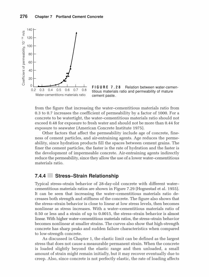
Therefore, increasing the water–cementitious materials ratio in freshconcrete has a severe effect on permeability. Figure 7.28 shows the typicalrelationship between the water–cementitious materials ratio and the coeffi-cient of permeability of mature cement paste (Powers 1954). It can be seen
MamCh07v3.qxd 8/3/05 7:16 PM Page 275
276 Chapter 7 Portland Cement Concrete
from the figure that increasing the water–cementitious materials ratio from0.3 to 0.7 increases the coefficient of permeability by a factor of 1000. For aconcrete to be watertight, the water–cementitious materials ratio should notexceed 0.48 for exposure to fresh water and should not be more than 0.44 forexposure to seawater (American Concrete Institute 1975).
Other factors that affect the permeability include age of concrete, fine-ness of cement particles, and air-entraining agents. Age reduces the perme-ability, since hydration products fill the spaces between cement grains. Thefiner the cement particles, the faster is the rate of hydration and the faster isthe development of impermeable concrete. Air-entraining agents indirectlyreduce the permeability, since they allow the use of a lower water–cementitiousmaterials ratio.
7.4.4 ■■ Stress–Strain Relationship
Typical stress–strain behavior of 28-day-old concrete with different water–cementitious materials ratios are shown in Figure 7.29 (Hognestad et al. 1955).It can be seen that increasing the water–cementitious materials ratio de-creases both strength and stiffness of the concrete. The figure also shows thatthe stress–strain behavior is close to linear at low stress levels, then becomesnonlinear as stress increases. With a water–cementitious materials ratio of0.50 or less and a strain of up to 0.0015, the stress–strain behavior is almostlinear. With higher water–cementitious materials ratios, the stress–strain behaviorbecomes nonlinear at smaller strains. The curves also show that high-strengthconcrete has sharp peaks and sudden failure characteristics when comparedto low-strength concrete.
As discussed in Chapter 1, the elastic limit can be defined as the largeststress that does not cause a measurable permanent strain. When the concreteis loaded slightly beyond the elastic range and then unloaded, a smallamount of strain might remain initially, but it may recover eventually due tocreep. Also, since concrete is not perfectly elastic, the rate of loading affects
140
00.2
Water-cementitions materials ratio
Coe
ffici
ent o
f per
mea
bili
ty, 1
0�14
m/s
0.3 0.4 0.5 0.6 0.7 0.8
120
100
80
60
40
20
F I G U R E 7 . 2 8 Relation between water-cemen-titious materials ratio and permeability of maturecement paste.
MamCh07v3.qxd 8/3/05 7:16 PM Page 276
Section 7.4 Properties of Hardened Concrete 277
0Strain, 10�6
Stre
ss, M
Pa
Stre
ss, k
si
50
0
8Water-cementitiousmaterials ratio � 0.33
0.40
0.50
0.67
1.00
01000 2000 3000 4000 5000
6
4
2
40
30
20
10F I G U R E 7 . 2 9 Typicalstress–strain relations for com-pressive Tests on 0.15 x 0.30-mconcrete cylinders at an age of28 days.
the stress–strain relation to some extent. Therefore, a specific rate of loadingis required for testing concrete. It is interesting to note that the shape of thestress–strain relationship of concrete is almost the same for both compres-sion and tension, although the tensile strength is much smaller than thecompressive strength. In fact, the tensile strength of concrete typically is ig-nored in the design of concrete structures.
The modulus of elasticity of concrete is commonly used in designingconcrete structures. Since the stress–strain relationship is not exactly linear,the classic definition of modulus of elasticity (Young’s modulus) is not ap-plicable. The initial tangent modulus of concrete has little practical impor-tance. The tangent modulus is valid only for a low stress level where thetangent is determined. Both secant and chord moduli represent “average”modulus values for certain stress ranges. The chord modulus (referred to asthe modulus of elasticity) in compression is more commonly used for con-crete and is determined according to ASTM C469. The method requiresthree or four loading and unloading cycles, after which the chord modulusis determined between a point corresponding to a very small strain valueand a point corresponding to either 40% of the ultimate stress or a specificstrain value. Normal-weight concrete has a modulus of elasticity of 14 GPato 40 GPa (2,000 ksi to 6,000 ksi).
Poisson’s ratio can also be determined using ASTM C469. Poisson’s ratiois used in advanced structural analysis of shell roofs, flat-plate roofs, andmat foundations. Poisson’s ratio of concrete varies between 0.11 and 0.21,depending on aggregate type, moisture content, concrete age, and compressivestrength. A value of 0.15 to 0.20 is commonly used.
It is interesting to note that both aggregate and cement paste, when testedindividually, exhibit linear stress–strain behavior. However, the stress–strainrelation of concrete is nonlinear. The reason for this behavior is attributed tothe microcracking in concrete at the interface between aggregate particles andthe cement paste (Shah and Winter 1968).
The modulus of elasticity of concrete increases when the compressivestrength increases, as demonstrated in Figure 7.29. There are several empirical
MamCh07v3.qxd 8/3/05 7:16 PM Page 277
278 Chapter 7 Portland Cement Concrete
relations between the modulus of elasticity of concrete and the compressivestrength. For normal-weight concrete, the relationship used in the UnitedStates for designing concrete structures is defined by the ACI Building Code as
(7.3a)
or
(7.3b)
where
modulus of elasticity,compressive strength.
Equation 7.3a is used for SI units, where both and are in MPa,whereas Equation 7.3b is used for the U.S. customary units, where both and are in psi. This relation is useful, since it relates the modulus of elas-ticity (needed for designing concrete structures) with the compressive strength,which can be measured easily in the laboratory.
Sample Problem 7.7
A normal-weight concrete has an average compressive strength of 30 MPa. What isthe estimated modulus of elasticity?
Solution
Testing of Hardened Concrete
Many tests are used to evaluate the hardened concrete properties, either in thelaboratory or in the field. Some of these tests are destructive, while others arenondestructive. Tests can be performed for different purposes; however, theyare mostly conducted to control the quality of the concrete and to check spec-ification compliance. Probably the most common test performed on hardenedconcrete is the compressive strength test, since it is relatively easy to performand since there is a strong correlation between the compressive strength andmany desirable properties (Neville 1981; Mehta and Monteiro 1993). Othertests include split tension, flexure strength, rebound hammer, penetration re-sistance, ultrasonic pulse velocity, and maturity tests.
7.5
Ec = 47312fcœ
= 473113021/2= 25,913 MPa = 25.9 GPa
f¿c
Ec
f¿cEc
f¿c = theEc = the
Ec = 57,0002fcœ
Ec = 4,7312fcœ
MamCh07v3.qxd 8/3/05 7:16 PM Page 278
Section 7.5 Testing of Hardened Concrete 279
7.5.1 ■■ Compressive Strength Test
The compressive strength test is the test most commonly performed onhardened concrete. Compressive strength is one of the main structural designrequirements to ensure that the structure will be able to carry the intendedload. As indicated earlier, compressive strength increases as the water–cementitious materials ratio decreases. Since the water–cementitious mate-rials ratio is directly related to the concrete quality, compressive strengthis also used as a measure of quality, such as durability and resistance toweathering. Thus, in many cases, designers specify a high compressivestrength of the concrete to ensure high quality, even if this strength is notneeded for structural support. The compressive strength of normal-weight concrete is between 20 MPa to 40 MPa (3000 psi to 6000 psi). In theUnited States, the test is performed on cylindrical specimens and is stan-dardized by ASTM C39. The specimen is prepared, either in the lab or inthe field, according to ASTM C192 or C31, respectively. Cores could also bedrilled from the structure following ASTM C42. The standard specimen sizeis 0.15 m (6 in.) in diameter and 0.30 m (12 in.) high, although other sizes witha height–diameter ratio of two can also be used. The diameter of the specimenmust be at least three times the nominal maximum size of the coarse aggregatein the concrete.
In the lab, specimens are prepared in three equal layers and are rodded25 times per layer. After the surface is finished, specimens are kept in themold for the first Specimens are then removed from themold and cured at either in saturated-lime wateror in a moist cabinet having a relative humidity of 95% or higher, until thetime of testing. Before testing, specimens are capped at the two bases to en-sure parallel surfaces. High-strength gypsum plaster, sulfur mortar, or aspecial capping compound can be used for capping and is applied with aspecial alignment device (ASTM C617). Using a testing machine, speci-mens are tested by applying axial compressive load with a specified rateof loading until failure (Figure 7.30). The compressive strength of the spec-imen is determined by dividing the maximum load carried by the speci-men during the test by the average cross-sectional area. The number ofspecimens and the number of test batches depend on established practiceand the nature of the test program. Usually three or more specimens aretested for each test age and test condition. Test ages often used are 7 daysand 28 days.
Note that the test specimen must have a height–diameter ratio of two.The main reason for this requirement is to eliminate the end effect due to thefriction between the loading heads and the specimen. Thus, we can guaranteea zone of uniaxial compression within the specimen. If the height–diameterratio is less than two, a correction factor can be applied to the results as in-dicated in ASTM C39.
The compressive strength of the specimen is affected by the specimensize. Increasing the specimen size reduces the strength, because there is agreater probability of weak elements where failure starts in large specimens
23 ; 1.7°C 173.4 ; 3°F2,24 ; 8 hours.
f¿c
MamCh07v3.qxd 8/3/05 7:16 PM Page 279
280 Chapter 7 Portland Cement Concrete
F I G U R E 7 . 3 0 Compressive strength test.
than in small specimens. In general, large specimens have less variabilityand better representation of the actual strength of the concrete than smallspecimens. Therefore, the 0.15-m by 0.30-m (6-in. by 12-in.) size is the mostsuitable specimen size for determining the compressive strength. However,some agencies use 0.10-m (4-in.) diameter by 0.20-m (8-in.) high specimens.The advantages of using smaller specimens are the ease of handling, lesspossibility of accidental damage, less concrete needed, the ability to use a
MamCh07v3.qxd 8/3/05 7:16 PM Page 280
Section 7.5 Testing of Hardened Concrete 281
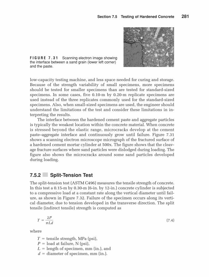
F I G U R E 7 . 3 1 Scanning electron image showingthe interface between a sand grain (lower left corner)and the paste.
low-capacity testing machine, and less space needed for curing and storage.Because of the strength variability of small specimens, more specimensshould be tested for smaller specimens than are tested for standard-sizedspecimens. In some cases, five 0.10-m by 0.20-m replicate specimens areused instead of the three replicates commonly used for the standard-sizedspecimens. Also, when small-sized specimens are used, the engineer shouldunderstand the limitations of the test and consider these limitations in in-terpreting the results.
The interface between the hardened cement paste and aggregate particlesis typically the weakest location within the concrete material. When concreteis stressed beyond the elastic range, microcracks develop at the cementpaste–aggregate interface and continuously grow until failure. Figure 7.31shows a scanning electron microscope micrograph of the fractured surface ofa hardened cement mortar cylinder at 500x. The figure shows that the cleav-age fracture surfaces where sand particles were dislodged during loading. Thefigure also shows the microcracks around some sand particles developedduring loading.
7.5.2 ■■ Split-Tension Test
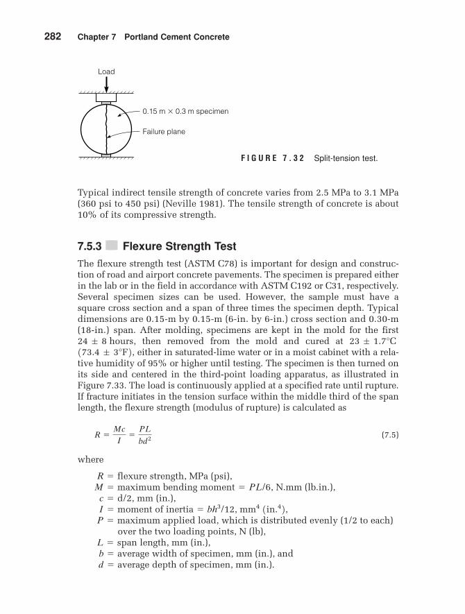
The split-tension test (ASTM C496) measures the tensile strength of concrete.In this test a 0.15-m by 0.30-m (6-in. by 12-in.) concrete cylinder is subjectedto a compressive load at a constant rate along the vertical diameter until fail-ure, as shown in Figure 7.32. Failure of the specimen occurs along its verti-cal diameter, due to tension developed in the transverse direction. The splittensile (indirect tensile) strength is computed as
(7.4)
where
strength, MPa (psi),at failure, N (psi),
of specimen, mm (in.), andof specimen, mm (in.).d = diameter
L = lengthP = loadT = tensile
T =
2P
pLd
MamCh07v3.qxd 8/3/05 7:16 PM Page 281
282 Chapter 7 Portland Cement Concrete
Typical indirect tensile strength of concrete varies from 2.5 MPa to 3.1 MPa(360 psi to 450 psi) (Neville 1981). The tensile strength of concrete is about10% of its compressive strength.
7.5.3 ■■ Flexure Strength Test
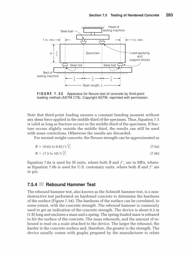
The flexure strength test (ASTM C78) is important for design and construc-tion of road and airport concrete pavements. The specimen is prepared eitherin the lab or in the field in accordance with ASTM C192 or C31, respectively.Several specimen sizes can be used. However, the sample must have asquare cross section and a span of three times the specimen depth. Typicaldimensions are 0.15-m by 0.15-m (6-in. by 6-in.) cross section and 0.30-m(18-in.) span. After molding, specimens are kept in the mold for the first
then removed from the mold and cured at either in saturated-lime water or in a moist cabinet with a rela-
tive humidity of 95% or higher until testing. The specimen is then turned onits side and centered in the third-point loading apparatus, as illustrated inFigure 7.33. The load is continuously applied at a specified rate until rupture.If fracture initiates in the tension surface within the middle third of the spanlength, the flexure strength (modulus of rupture) is calculated as
(7.5)
where
strength, MPa (psi),bending N.mm (lb.in.),
mm (in.),of
applied load, which is distributed evenly (1/2 to each) over the two loading points, N (lb),
length, mm (in.),width of specimen, mm (in.), anddepth of specimen, mm (in.).d = average
b = averageL = span
P = maximuminertia = bh3/12, mm4 1in.42,I = moment
c = d/2,moment = PL/6,M = maximum
R = flexure
R =
Mc
I=
PL
bd2
173.4 ; 3°F2, 23 ; 1.7°C 24 ; 8 hours,
0.15 m � 0.3 m specimen
Failure plane
Load
F I G U R E 7 . 3 2 Split-tension test.
MamCh07v3.qxd 8/3/05 7:16 PM Page 282
Section 7.5 Testing of Hardened Concrete 283
Note that third-point loading ensures a constant bending moment withoutany shear force applied in the middle third of the specimen. Thus, Equation 7.5is valid as long as fracture occurs in the middle third of the specimen. If frac-ture occurs slightly outside the middle third, the results can still be usedwith some corrections. Otherwise the results are discarded.
For normal-weight concrete, the flexure strength can be approximated as
(7.6a)
(7.6b)
Equation 7.6a is used for SI units, where both R and are in MPa, where-as Equation 7.6b is used for U.S. customary units, where both R and arein psi.
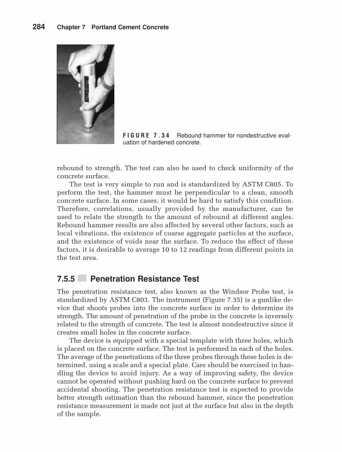
7.5.4 ■■ Rebound Hammer Test
The rebound hammer test, also known as the Schmidt hammer test, is a non-destructive test performed on hardened concrete to determine the hardnessof the surface (Figure 7.34). The hardness of the surface can be correlated, tosome extent, with the concrete strength. The rebound hammer is commonlyused to get an indication of the concrete strength. The device is about 0.3 m(1 ft) long and encloses a mass and a spring. The spring-loaded mass is releasedto hit the surface of the concrete. The mass rebounds, and the amount of re-bound is read on a scale attached to the device. The larger the rebound, theharder is the concrete surface and, therefore, the greater is the strength. Thedevice usually comes with graphs prepared by the manufacturer to relate
f¿
f¿c
R = 17.5 to 1022fcœ
R = 10.62 to 0.8322fcœ
Specimen Load-applyingand
support blocks
1 in. min.
Steel ball
Steel ballSteel rod
Bed oftesting machine
Head oftesting machine
Span length, L
L3
L3
L3
L3
d �
1 in. min.
F I G U R E 7 . 3 3 Apparatus for flexure test of concrete by third-pointloading method (ASTM C78). Copyright ASTM. reprinted with permission.
MamCh07v3.qxd 8/3/05 7:16 PM Page 283
284 Chapter 7 Portland Cement Concrete
rebound to strength. The test can also be used to check uniformity of theconcrete surface.
The test is very simple to run and is standardized by ASTM C805. Toperform the test, the hammer must be perpendicular to a clean, smoothconcrete surface. In some cases, it would be hard to satisfy this condition.Therefore, correlations, usually provided by the manufacturer, can beused to relate the strength to the amount of rebound at different angles.Rebound hammer results are also affected by several other factors, such aslocal vibrations, the existence of coarse aggregate particles at the surface,and the existence of voids near the surface. To reduce the effect of thesefactors, it is desirable to average 10 to 12 readings from different points inthe test area.
7.5.5 ■■ Penetration Resistance Test
The penetration resistance test, also known as the Windsor Probe test, isstandardized by ASTM C803. The instrument (Figure 7.35) is a gunlike de-vice that shoots probes into the concrete surface in order to determine itsstrength. The amount of penetration of the probe in the concrete is inverselyrelated to the strength of concrete. The test is almost nondestructive since itcreates small holes in the concrete surface.
The device is equipped with a special template with three holes, whichis placed on the concrete surface. The test is performed in each of the holes.The average of the penetrations of the three probes through these holes is de-termined, using a scale and a special plate. Care should be exercised in han-dling the device to avoid injury. As a way of improving safety, the devicecannot be operated without pushing hard on the concrete surface to preventaccidental shooting. The penetration resistance test is expected to providebetter strength estimation than the rebound hammer, since the penetrationresistance measurement is made not just at the surface but also in the depthof the sample.
F I G U R E 7 . 3 4 Rebound hammer for nondestructive eval-uation of hardened concrete.
MamCh07v3.qxd 8/3/05 7:16 PM Page 284
Section 7.5 Testing of Hardened Concrete 285
7.5.6 ■■ Ultrasonic Pulse Velocity Test
The ultrasonic pulse velocity test (ASTM C597) measures the velocity ofan ultrasonic wave passing through the concrete (Figure 7.36). In this test,the path length between transducers is divided by the travel time to de-termine the average velocity of wave propagation. Attempts have beenmade to correlate pulse velocity data with concrete strength parameters.No good correlations were found, since the relationship between pulse ve-locity and strength data is affected by a number of variables, such as ageof concrete, aggregate–cement ratio, aggregate type, moisture condition,and location of reinforcement (Mehta and Moneiro 1993). This test is usedto detect cracks, discontinuities, or internal deterioration in the structureof concrete.
7.5.7 ■■ Maturity Test
Maturity of a concrete mixture is defined as the degree of cement hydra-tion, which varies as a function of both time and temperature. Therefore,it is assumed that, for a particular concrete mixture, strength is a function ofmaturity. Maturity meters (Figure 7.37) have been developed to provide anestimate of concrete strength by monitoring the temperature of concretewith time. This test (ASTM C1074) is performed on fresh concrete and con-tinued for several days. The maturity meter must be calibrated for eachconcrete mix.
F I G U R E 7 . 3 5 Windsor probe testdevice.
MamCh07v3.qxd 8/3/05 7:16 PM Page 285
286 Chapter 7 Portland Cement Concrete
F I G U R E 7 . 3 6 Ultrasonic pulse velocity apparatus (Courtesy of James Instru-ment Inc.).
F I G U R E 7 . 3 7 Checking the maturity of fresh concreteusing the maturity meter.
MamCh07v3.qxd 8/3/05 7:16 PM Page 286
Section 7.6 Alternatives to Conventional Concrete 287
Alternatives to Conventional Concrete
There are several alternatives that increase the flexibility and applicationsof concrete. While a technical presentation of materials for each of thesetechnologies is beyond the scope of this book, the engineer should be awareof some of the materials used to provide additional capabilities of concrete.Some of these alternatives include the following:
Self-consolidating concrete (SCC), also known as self-compacting concrete, isa highly flowable, nonsegregating concrete that can spread into place, fill theformwork, and encapsulate the reinforcement, without any mechanical con-solidation (NRMCA). Some of the advantages of using SCC are the following:
1. It can be placed at a faster rate, with no mechanical vibration and lessscreeding, resulting is savings in placement costs.
2. It improves and makes more uniform the architectural surface finishwith little or no remedial surface work.
3. It improves ease of filling restricted sections and hard-to-reach areas.This allows the designer to create structural and architectural shapesnot achievable with conventional concrete.
4. It improves consolidation around reinforcement and bond with rein-forcement.
5. It improves pumpability.
Two important properties specific to self-consolidating concrete in itsplastic state are its flowability and stability. The high flowability of SCC isachieved by using high-range water-reducing admixtures without addingextra mixing water. The stability, or resistance to segregation, is attained byincreasing the amount of fines and/or by using admixtures that modify theviscosity of the mixture. Fines could be either cementitious materials ormineral fines.
The most common field test that has been used to measure the flowabil-ity and stability of SCC is a modified version of the slump test, discussed
7.6
MamCh07v3.qxd 8/3/05 7:16 PM Page 287
288 Chapter 7 Portland Cement Concrete
earlier. In this slump flow test, the slump cone is completely filled, withoutconsolidation. The cone is lifted, and the spread of the concrete is measured,as shown in Figure 7.38. The flowability is measured by the spread, or slumpflow. The spread typically ranges from 455 to 810 mm (18 to 32 inches), de-pending on the requirements of the project. The resistance to segregation, orstability, is measured with the visual stability index (VSI). The VSI is estab-lished on the basis of whether bleed water is observed at the leading edge ofthe spreading concrete or aggregates pile at the center. VSI values range from0 for “highly stable” to 3 for unacceptable stability.
During the slump flow test, the viscosity can be measured by the rate atwhich the concrete spreads. The time taken for the concrete to reach a spreaddiameter of 50 cm (20 inches) from the moment the sump cone is lifted upis measured. This is called the measurement and typically variesbetween 2 and 10 seconds for SCC. A value indicates a more vis-cous mix, which is more appropriate for concrete in applications with con-gested reinforcement or in deep sections. A lower value may beappropriate for concrete that has to travel long horizontal distances withoutmuch obstruction.
7.6.2 ■■ Flowable Fill
Flowable fill is a self-leveling and self-compacting, cementitious materialwith an unconfined compressive strength of 8.3 MPa (1200 psi) or less.Flowable fill is primarily used as a backfill material in lieu of compactedgranular fill (Figure 7.39). Flowable fill is also commonly referred to as con-trolled low-strength material (CLSM), controlled density fill (CDF), flowablecompacting fill, lean fill, unshrinkable fill, flow mortar, fly ash flow, and liquiddirt (NRMCA).
T50 1T202T50 1T202
T50 1T202
F I G U R E 7 . 3 8 Measuring the spread dur-ing the slump flow test.
MamCh07v3.qxd 8/3/05 7:16 PM Page 288
Section 7.6 Alternatives to Conventional Concrete 289
F I G U R E 7 . 3 9 Filling a sink hole with flowable fill.
The flowable fill mix consists of cement, sand, and water typically mixedwith fly ash, ground granulated blast furnace (GGBF) slag, and/or air gener-ating admixtures. The type and proportions of ingredients used to make theflowable fill can largely change its properties to match its intended use.
One of the unique properties of flowable fill that makes it advantageouscompared with compacted granular fill is its flowability. High flowabilityand self-leveling characteristics allow flowable fill to eliminate voids andaccess spaces that prove to be difficult or impossible with compacted gran-ular fill.
When the flowable fill is placed in the cavity, its initial in-place volumeis slightly reduced in the order of 10 mm per meter (1/8 inch per foot) ofdepth. This settlement is caused by the displacement of water and the re-lease of entrapped air as a result of consolidation. Once the flowable fill ishardened, the settlement stops and the volume does not change.
Flowable fill can be proportioned to have a wide range of compressivestrength. However, the most commonly used flowable fill mixtures are pro-portioned with consideration of possible excavation in future years andrange in compressive strengths between 0.35 MPa and 1 MPa (50 and 150 psi).Flowable fill with a compressive strength less than 150 psi may be exca-vated manually, while at the same time having adequate bearing capacity tosupport external loads, such as the weight of a vehicle. Flowable fill ex-hibiting strengths between 150 and 300 psi will require mechanical equipmentfor excavation. If the strength exceeds 2 MPa (300 psi), the material is notconsidered excavatable.
MamCh07v3.qxd 8/3/05 7:16 PM Page 289
290 Chapter 7 Portland Cement Concrete
Flowable fill has several advantages over compacted granular backfill.Flowable fill does not require compaction, which is a main concern withgranular backfill. Flowable fill can also reach inaccessible locations, such asplaces around pipes, which are hard to reach with granular backfill. Flow-able fill also has a greater bearing capacity than compacted granular fill andno noticeable settlement. It can even be placed in standing water. These ad-vantages result in reduced in-place costs for labor and equipment, as well astime saving during construction.
Flowable fill is typically used as backfill for utility trenches, retainingwalls, pipe bedding, and building excavation. It is also used as structural fillfor poor soil conditions, mud jacking, floor and footing support, and bridgeconversion. Other uses include pavement base, erosion control, and voidfilling. Flowable fill has been getting more common in recent years and ismostly available at local ready-mix producers.
7.6.3 ■■ Shotcrete
Shotcrete is mortar or small-aggregate concrete that is sprayed at high veloci-ty onto a surface (see Figures 7.40 and 7.41). Shotcrete, also known as “gunite”and “sprayed concrete,” is a relatively dry mixture that is consolidated by theimpact force and can be placed on vertical or horizontal surfaces withoutsagging.
F I G U R E 7 . 4 0 Constructing a swimming pool using shotcrete.
MamCh07v3.qxd 8/3/05 7:16 PM Page 290
Section 7.6 Alternatives to Conventional Concrete 291
F I G U R E 7 . 4 1 Shotcrete used in lining a tunnel.
Shotcrete is applied by either the dry or wet process. In the dry process,a premixed blend of cement and damp aggregate is propelled through a hoseby compressed air to a nozzle, while the water is added at the nozzle. In thewet process, all ingredients are premixed and pumped through a hose to thenozzle and forced to the surface using compressed air. In either case, the noz-zle should be held perpendicular to the surface to reduce the rebound ofcoarse aggregates off the surface. The nozzle is held about 0.5 to 1.5 m (1.5 to5 ft) away from the surface.
Supplementary cementitious materials, such as fly ash and silica fume,can be used in shotcrete to improve workability, chemical resistance, anddurability. Accelerating admixtures can also be used to reduce the time ofinitial set and to allow buildup of thicker layers of shotcrete in a single pass.Steel fibers may also be used to improve flexural strength, ductility, andtoughness (Kosmatka et al. 2002).
7.6.4 ■■ Lightweight Concrete
Students competing in the annual ASCE concrete canoe competition fre-quently produce concrete with a unit weight less than water. The ACI Guide
MamCh07v3.qxd 8/3/05 7:16 PM Page 291
292 Chapter 7 Portland Cement Concrete
for the Structural Lightweight Aggregate Concrete requires a 28-day com-pressive strength of 17 MPa (2500 psi) and an air-dried unit weight of lessthan for structural lightweight concrete. The use oflightweight concrete in a structure is usually predicated on the overall costof the structure; the concrete may cost more, but the reduced dead weightcan reduce structural and foundation costs.
The mix proportions for lightweight concrete must compensate for the ab-sorptive nature of the aggregates. Generally, lightweight aggregates are highlyabsorptive and can continue to absorb water for an extended period of time(Figures 7.42 and 7.43). This makes the determination of a water–cementitiousmaterials ratio problematical. In addition, the lightweight aggregates tend tosegregate by floating to the surface. A minimum slump mix, with air entrain-ing, is used to mitigate this effect.
Nonstructural applications of very lightweight concrete have also beendeveloped. Concrete made with styrofoam “aggregates” has been used for in-sulation in some building construction.
7.6.5 ■■ Heavyweight Concrete
Biological shielding used for nuclear power plants, medical units, and atomicresearch and test facilities requires massive walls to contain radiation. Con-crete is an excellent shielding material. For biological shields, the mass of
1850 kg/m3 1115 lb/ft32
F I G U R E 7 . 4 2 Aggregate used for lightweight concrete.
MamCh07v3.qxd 8/3/05 7:16 PM Page 292
Section 7.6 Alternatives to Conventional Concrete 293
the concrete can be increased with the use of heavyweight aggregates. Theaggregates can be either natural or manufactured. Natural heavyweight aggre-gates include barite, magnetite, hematite, geothite, illmenite, and ferrophos-phorus. The specific gravity of these aggregates range from 3.4 to 6.5. Steel,with a specific gravity of 7.8, can be used as aggregate for heavyweight con-crete (Figure 7.44). However, the specific gravity of the aggregates makesworkability and segregation of heavyweight concrete problematical. Using ahigher proportion of sand improves the workability. The workability prob-lem can be avoided by preplacing aggregate, then filling the voids betweenaggregate particles with grout of cement, sand, water, and admixtures.ASTM C637, Specifications for Aggregates for Radiation Shielding Concreteand ASTM C637, Nomenclature of Constituents of Aggregates for RadiationShielding Concrete provide further information on heavyweight concretepractices.
7.6.6 ■■ High-Strength Concrete
Concrete made with normal-weight aggregate and having compressivestrengths greater than 40 MPa (6000 psi) is considered to be high-strengthconcrete. Producing a concrete with more than 40 MPa compressive strengthrequires care in the proportioning of the components and in quality control
F I G U R E 7 . 4 3 ASCE students at Arizona State University making a concretecanoe using lightweight concrete.
MamCh07v3.qxd 8/3/05 7:16 PM Page 293
294 Chapter 7 Portland Cement Concrete
during construction. The microstructure of concrete with a compressivestrength greater than 40 MPa is considerably different from that of conven-tional concrete. In particular, the porosity of the cement paste and the tran-sition zone between the cement paste and the aggregate are the controllingfactors for developing high strength. This porosity is controlled by thewater–cementitious materials ratio. The development of superplasticizershas permitted the development of high-strength concrete that is workableand flowable at low water–cementitious materials ratios. In addition, high-strength concrete has excellent durability due to its tight pore structure. Inthe United States, high-strength concrete is used primarily for skyscrapers.The high-strength and corresponding high elastic modulus allow for reducedstructural element size.
7.6.7 ■■ Shrinkage-Compensating Concrete
Normal concrete shrinks at early ages, especially if it is not properly cured,as discussed earlier in this chapter. The addition of alumina powders to thecement can cause the concrete to expand at early ages. Shrinkage-compen-sating cement is marketed as Type K cement. Expansive properties can beused to advantage by restraining the concrete, either by reinforcing or byother means, at early ages. As the restrained concrete tries to expand, com-pressive stresses are developed. These compressive stresses reduce the ten-sile stresses developed by drying shrinkage, and the chance of the concretecracking due to drying shrinkage is reduced. Details on the design and useof shrinkage-compensating concrete are available in ACI Committee 223 re-port Recommendations for the Use of Shrinkage-Compensating Cements.
7.6.8 ■■ Polymers and Concrete
Polymers can be used in several ways in the production of concrete. The poly-mer can be used as the sole binding agent to produce polymer concrete. Poly-mers can be mixed with the plastic concrete to produce polymer–portlandcement concrete. Polymers can be applied to hardened concrete to producepolymer-impregnated concrete.
F I G U R E 7 . 4 4 Steel used as ag-gregate for heavy weight concrete.
MamCh07v3.qxd 8/3/05 7:16 PM Page 294
Section 7.6 Alternatives to Conventional Concrete 295
Polymer concrete is a mixture of aggregates and a polymer binder. Thereare a wide variety of polymers that can be mixed with aggregates to makepolymer concrete. Some of these can be used to make rapid-setting concretethat can be put in service in under an hour after placement. Others are for-mulated for high strength; 140 MPa (20,000 psi) is possible. Some have goodresistance to chemical attack. A common characteristic is that most polymerconcretes are expensive, limiting their application to situations in whichtheir unique characteristics make polymer concrete a cost-effective alterna-tive to conventional concrete.
Polymer–portland cement concrete incorporates a polymer into the pro-duction of the portland cement concrete. The polymer is generally an elas-tomeric emulsion, such as latex.
7.6.9 ■■ Fiber-Reinforced Concrete
The brittle nature of concrete is due to the rapid propagation of microc-racking under applied stress. However, with fiber-reinforced concrete, fail-ure takes place due to fiber pull-out or debonding. Unlike plain concrete,fiber-reinforced concrete can sustain load after initial cracking. This effec-tively improves the toughness of the material. In addition, the flexuralstrength of the concrete is improved by up to 30%. For further informationon the design and applications of fiber-reinforced concrete, consult the ACIGuide for Specifying, Mixing, Placing and Finishing Steel Fiber ReinforcedConcrete.
Fibers are available in a variety of sizes, shapes, and materials (Figure7.45). The fibers can be made of steel, plastic, glass, and natural materials.Steel fibers are the most common. The shape of fibers is generally describedby the aspect ratio, length/diameter. Steel fibers generally have diametersfrom 0.25 mm to 0.9 mm (0.01 in. to 0.035 in.) with aspect ratios of 30 to150. Glass fiber elements’ diameters range from 0.013 mm to 1.3 mm (0.005in. to 0.05 in.).
F I G U R E 7 . 4 5 Fibers used for fiber-reinforced concrete
MamCh07v3.qxd 8/3/05 7:16 PM Page 295
296 Chapter 7 Portland Cement Concrete
The addition of fibers to concrete reduces the workability. The extent ofreduction depends on the aspect ratio of the fibers and the volume concen-tration. Generally, due to construction problems, fibers are limited to a max-imum of 2% by volume of the mix. Admixtures can be used to restore someof the workability to the mix.
Since the addition of fibers does not greatly increase the strength of con-crete, its use in structural members is limited. In beams, columns, suspendedfloors, etc., conventional reinforcing must be used to carry the total tensileload. Fiber-reinforced concrete has been successfully used for floor slabs,pavements, slope stabilization, and tunnel linings.
7.6.10 ■■ Roller-Compacted Concrete
Based on the unique requirements for mass concrete used for dam con-struction, roller-compacted concrete (RCC) was developed. This materialuses a relatively low cement factor, relaxed gradation requirements, and awater content selected for construction considerations rather than strength.RCC is a no-slump concrete that is transported, placed, and compacted withequipment used for earth and rockfill dam construction. The RCC is hauledby dump trucks, spread with bulldozers, and compacted with vibrationcompactors. Japanese experience using RCC in construction found severaladvantages:
1. The mix is economical, because of the low cement content.2. Formwork is minimal, because of the layer construction method.3. The low cement factor limits the heat of hydration, reducing the need
for external cooling of the structure.4. The placement costs are lower than those for conventional concrete
methods, due to the use of high-capacity equipment and rapid place-ment rates.
5. The construction period is shorter than that for conventional concrete.
In addition, experience in the United States has demonstrated that RCCin-place material costs are about one-third those of conventional concrete.The two primary applications of RCC have been for the construction of damsand large paved areas, such as military tank parking aprons.
7.6.11 ■■ High-Performance Concrete
While the current specifications for concrete have provided a material thatperforms reasonably well, there is concern that the emphasis on strength inthe mix design process has led to concrete that is inadequate in other per-formance characteristics. This has led to an interest in developing specifi-cations and design methods for what has been termed high-performanceconcrete (HPC). The American Concrete Institute (ACI) defines HPC as con-crete that meets special performance and uniformity requirements, whichcannot always be obtained using conventional ingredients, normal mixing
MamCh07v3.qxd 8/3/05 7:16 PM Page 296
Section 7.6 Alternatives to Conventional Concrete 297
procedures, and typical curing practices. These requirements may includethe following enhancements:
ease of placement and compactionlong-term mechanical propertiesearly-age strengthtoughnessvolume stabilityextended life in severe environments
These enhanced characteristics may be accomplished by altering the ag-gregate gradation, including special admixtures, and improving mixing andplacement practices. Currently, a compressive strength in the order of 70 to175 MPa (10,000 to 25,000 psi) can be obtained. As the need for HPC is bet-ter understood and embraced by the engineering community, there will prob-ably be a transition in concrete specification from the current prescriptivemethod to the performance-based or performance-related specifications. AStrategic Highway Research Program (SHRP) study (Zia et al. 1991) definedHPC as
maximum water–cementitious materials ratio of 0.35;minimum durability factor of 80%, as determined by ASTM C 666,
Procedure A; andminimum strength criteria of either:
a. 21 MPa (3000 psi) within 4 hours after placement (Very EarlyStrength, VES),
b. 34 MPa (5000 psi) within 24 hours (High Early Strength, HES), orc. 69 MPa (10,000 psi) within 28 days (Very High Strength, VHS).
Thus, high-performance concrete is characterized by special performance,both short-term and long-term, and uniformity in behavior (Nawy 1996).Such requirements cannot always be achieved by using only conventionalmaterials or applying conventional practices. Since concrete is the mostwidely used construction material worldwide, new concrete constructionhas to utilize the currently available new technology in order to eliminatecostly future rehabilitation.
Revolutionary new construction materials and modifications and im-provements in the behavior of traditional materials have been developed inthe last three decades. These developments have been considerably facilitat-ed by increased knowledge of the molecular structure of materials, studies oflong-term failures, development of more powerful instrumentation and mon-itoring techniques, and the need for stronger and better performing materials,suitable for larger structures, longer spans, and more ductility.
In spite of the current advances of the concrete technology and the devel-opment of high-performance concretes, it is expected that the concrete indus-try will continue improving through the development of new componentsand admixtures, microstructural studies, blended cement compositions, bettermaterial selection and proportioning techniques, and more efficient placementtechniques.
MamCh07v3.qxd 8/3/05 7:16 PM Page 297
298 Chapter 7 Portland Cement Concrete
S U M M A R Y
The design of durable portland cement concrete materials is the direct re-sponsibility of civil engineers. Selection of the proper proportions of portlandcement, water, aggregates, and admixtures, along with good constructionpractices, dictates the quality of concrete used in structural applications.Using the volumetric mix design method presented in this chapter will leadto concrete with the required strength and durability. However, the proper de-sign of portland cement concrete is irrelevant unless proper construction pro-cedures are followed, including the appropriate mixing, transporting, placing,and curing of the concrete. To ensure that these processes produce concretewith the desired properties, a variety of quality control tests are performedby civil engineers, including slump tests, air content tests, and strength-gain-with-time tests.
While the vast majority of concrete projects are constructed with conven-tional materials, there are a variety of important alternative concrete formula-tions available for specialty applications. These alternatives are introduced inthis chapter; however, the technology associated with these alternatives is rel-atively complex, and further study is required in order to fully understand thebehavior of these materials.
Q U E S T I O N S A N DP R O B L E M S
7.1 The design engineer specifies a concrete strength of 5500 psi. Deter-mine the required average compressive strength fora. a new plant where s is unknownb. a plant where for 22 test resultsc. a plant with extensive history of producing concrete with
d. a plant with extensive history of producing concrete with
7.2 A project specifies a concrete strength of 24.1 MPa. Materials engi-neers will design the mix for a strength higher than that to accountfor variabilities.a. Calculate the required average compressive strength of the mix de-
sign if the mixing plant has a standard deviation of b. Using the ACI code equation, estimate what would be the modulus
of elasticity of this concrete at the required compressive strength.
s = 3.8 MPa.
s = 600 psi
s = 400 psi
s = 500 psi
MamCh07v3.qxd 8/3/05 7:16 PM Page 298
Questions and Problems 299
7.3 A project specifies a concrete strength of at least 3000 psi. Materialsengineers will design the mix for a strength higher than that. Calcu-late the required average compressive strength of the mix design ifthe standard deviation is Estimate the modulus of elas-ticity of the concrete at the required average compressive strength(the calculated strength, not the given strength).
7.4 What is your recommendation for the maximum nominal size ofcoarse aggregate for the following situation?A continuously reinforced concrete pavement cross section containsa layer of No. 6 reinforcing bars at 6-inch centers, such that the steelis just above mid-depth of a 10-inch thick slab. Cover over the top ofthe steel is therefore about 4 inches.
7.5 A concrete mix with a 3-inch slump, w/c ratio of 0.50, and sandwith a fineness modulus of 2.4 contains 1700 lb of coarse aggregate.Compute the required weight of coarse aggregate per cubic yard. Toadjust the mix so as to increase the compressive strength, the water-to-cement ratio is reduced to 0.45. Will the quantity of coarse aggre-gate increase, decrease, or stay the same? Explain your answer.
7.6 You are working on a concrete mix design that requires each cubicyard of concrete to have 0.45 water-to–cementitious materials ratio,
of dry gravel, 4% air content, and of cement.The available gravel has a specific gravity of a mois-ture content of 1.6%, and absorption of 2.4%. The available sandhas a specific gravity of a moisture content of 4.8%, andabsorption of 1.5%. For each cubic yard of concrete needed on thejob, calculate the weights of cement, moist gravel, moist sand, andwater that should be added to the batch. Summarize and total themix design when finished (don’t include air entrainer in summary).
7.7 Design the concrete mix according to the following conditions:
Design EnvironmentBuilding frameRequired design Minimum Minimum space between Minimum cover over Statistical data indicate a standard deviation of compressive
strength of 2.1 MPa is expected (more than 30 samples).Only air entrainer is allowed.
Available MaterialsAir entrainer: Manufacture specification 6.3 ml/1% air/100 kg
cement.Coarse aggregate: 19 mm maximum size, river gravel (rounded)Bulk oven-dry specific Oven-dry rodded Moisture Fine aggregate: Natural sand
content = 2.5%density = 1761 kg/m3
Absorption = 0.3%gravity = 2.55,
rebar = 40 mmrebar = 40 mm
dimension = 150 mmstrength = 27.6 MPa
Gsand = 2.5,
Ggravel = 2.7,565 lb/ft31963 lb/yd3
s = 350 psi.
MamCh07v3.qxd 8/3/05 7:16 PM Page 299
300 Chapter 7 Portland Cement Concrete
Bulk oven-dry specific Moisture Fineness
7.8. Design the concrete mix according to the following conditions.
Design EnvironmentPavement slab, Bozeman, Montana (cold climate)Required design Slab Statistical data indicate a standard deviation of compressive
strength of 250 psi is expected (more than 30 samples).Only air entrainer is allowed.
Available MaterialsAir entrainer: Manufacture specification is 0.15 fl oz/1% air/100
lb cement.Coarse aggregate: 2 in. maximum size, crushed gravel (angular)Bulk oven-dry specific Oven-dry rodded Moisture Fine aggregate: Natural sandBulk oven-dry specific Moisture Fineness
7.9 The design of a concrete mix requires of gravel in drycondition, of sand in dry condition, and offree water. The gravel available at the job site has a moisture contentof 0.8% and absorption of 1.5%, and the available sand has a mois-ture content of 1.1% and absorption of 1.3%. What are the massesof gravel, sand, and water per cubic meter that should be used at thejob site?
7.10 Design a non-air-entrained concrete mix for a small job with a maxi-mum gravel size of 25 mm (1 in.). Show the results as follows:a. masses of components to produce 2000 kg (4400 lb) of concrete.b. volumes of components to produce of concrete.
7.11 Design a non-air-entrained concrete mix for a small job with a maxi-mum gravel size of Show the results as follows:a. weights of components to produce 5000 lb of concrete.b. volumes of components to produce of concrete.
7.12 Why is it necessary to measure the air content of concrete at the jobsite rather than at the batch plant? Name one of the methods used tomeasure the air content of concrete.
7.13 What do we mean by curing concrete? What would happen if con-crete is not cured?
7.14 Discuss five different methods of concrete curing.
7.15 Discuss the change in volume of concrete at early ages.
1 yd3
3�4 in.
1 m3 136 ft32
157 kg/m3582 kg/m31173 kg/m3
modulus = 2.68content = 3.67%
Absorption = 0.2%gravity = 2.54,
content = 1%density = 120 pcf
Absorption = 0.1%gravity = 2.573,
thickness = 12 in.strength = 3000 psi
modulus = 2.47content = 2%
Absorption = 0.5%gravity = 2.659,
MamCh07v3.qxd 8/3/05 7:16 PM Page 300
Questions and Problems 301
7.16 Discuss the creep response of concrete structures. Provide examplesof the effect of creep on concrete structures.
7.17. On one graph, draw a sketch showing the typical relationship be-tween the stress and strain of concrete specimens with high and lowwater–cementitious materials ratios. Label all axes and curves. Com-ment on the effect of increasing the water–cementitious materialsratio on the stress–strain response.
7.18 Using Figure 7.29,a. Determine the ultimate stress at each water–cementitious materials
ratio.b. Determine the secant modulus at 40% of the ultimate stress at
each water–cementitious materials ratio.c. Plot the relationship between the secant moduli and the ultimate
stresses.d. Plot the relationship between the moduli and the ultimate stresses
on the same graph of part (c), using the relation of the ACI BuildingCode (Equation 7.3).
e. Compare the two relations and comment on any discrepancies.
7.19 A normal-weight concrete has an average compressive strength of4500 psi. What is the estimated modulus of elasticity?
7.20 Discuss the significance of the compressive strength test on concrete.Draw a graph to show the relationship between compressivestrength and water–cementitious materials ratio for different curingtimes (Label all axes and curves).
7.21 What is the standard size of PCC specimens to be tested for com-pressive strength? If a smaller size is used, which size is expected toprovide higher compressive strengths? Why? Which size providesstrengths close to that of an actual concrete structure?
7.22 A short plain concrete column with dimensions ofis to be constructed. If the compressive
strength of the concrete is 5000 psi, what is the maximum load thatcan be applied to this column using a factor of safety of 1.2?
7.23 What is the purpose of performing the flexure test on concrete?How are the results of this test related to the compressive strengthtest results?
7.24 What are the advantages of using a third-point loading flexuretest over a center-point loading flexure test? Draw a shear forcediagram and a bending moment diagram for each case to supportyour answer.
7.25 Consider a standard flexural strength specimen of length L, width a,and depth a. Assume third point loading where the load at failurefrom the test machine is P, which is distributed evenly (1/2 to each)over the two loading points. Derive the equation for calculating themodulus of rupture of the beam in terms of P, L, and a.
12 in. * 12 in. * 36 in.
MamCh07v3.qxd 8/3/05 7:16 PM Page 301
302 Chapter 7 Portland Cement Concrete
7.26 The flexure strength test was performed on a concrete beam havinga cross section of 0.15 m by 0.15 m and a span of 0.45 m. If the loadat failure was 35.7 kN, calculate the flexure strength of the concrete.
7.27 A normal-weight concrete has an average compressive strength of 20MPa. What is the estimated flexure strength?
7.28 Discuss two nondestructive tests to be performed on hardened con-crete. Show the basic principles behind the tests and how they areperformed.
7.29 Discuss the concept of concrete maturity meters.7.30 Discuss four alternatives that increase the use and application of
conventional concrete.7.31 What is self-consolidating concrete? How are its properties
achieved? How are these properties measured?7.32 What is flowable fill? Discuss its ingredients and its advantages.7.33 Discuss the concept of high-performance concrete. Discuss some of
its properties that make it preferred over conventional concrete.7.34 Comparing PCC with mild steel, answer the following questions:
a. Which one is stronger?b. Which one has a higher modulus or stiffness?c. Which one is more brittle?d. What is the range of compressive strength for a typical PCC?e. What is the compressive strength for a high-strength concrete?f. What would be a reasonable range for PCC modulus?
7.35 In a ready-mix plant, cylindrical samples are prepared and testedperiodically to detect any mix problem and to ensure that the com-pressive strength is higher than the lower specification limit. Theminimum target value was set at 4000 psi. The following compres-sive strength data were collected.
a. Calculate the mean, standard deviation, and the coefficient ofvariation of the data.
b. Using a spreadsheet program, create a control chart for these datashowing the target value and the lower specification limit. Is theplant production meeting the specification requirement? If not,comment on possible reasons. Comment on the data scatter.
References
American Concrete Institute. Specifications for Structural Concrete. ACICommittee 301 Report, ACI 301–99. Farmington Hills, MI: AmericanConcrete Institute, 1999.
American Concrete Institute. Guide for Concrete Floor and Slab Construc-tion. ACI Committee 302 Report, ACI 302.1R-96. Farmington Hills, MI:American Concrete Institute, 1996.
American Concrete Institute. Hot-Weather Concreting. ACI Committee 305Report, ACI 305R-99. Farmington Hills, MI: American Concrete Insti-tute, 1999.
American Concrete Institute. Cold-Weather Concreting. ACI Committee 306Report, ACI 306R-88. Farmington Hills, MI: American Concrete Insti-tute, 1997.
American Concrete Institute. Standard Practice for Selecting Proportions forNormal, Heavyweight and Mass Concrete. ACI Committee 211 Report,ACI 211.1–91. Farmington Hills, MI: American Concrete Institute, 1991.
American Concrete Institute. Standard Practice for Curing Concrete. ACICommittee 308 Report, ACI 308–92. Farmington Hills, MI: AmericanConcrete Institute, 1997.
American Concrete Institute. Building Code Requirements for ReinforcedConcrete. ACI Committee 318 Report, ACI 318–99. Farmington Hills,MI: American Concrete Institute, 1999.
Hognestad, E., N. W. Hanson, and D. McHenry. Concrete Stress Distribu-tion in Ultimate Strength Design. Development Department BulletinDX006. Skokie, IL: Portland Cement Association, 1955.
Kosmatka, S. H., B. Kerkhoff, and W. C. Panarese. Design and Control of Con-crete Mixtures. 14th ed. Skokie, IL: Portland Cement Association, 2002.
Mehta, P. K. and P. J. M. Monteiro. Concrete Structure, Properties, and Ma-terials. 2nd ed. Upper Saddle River, NJ: Prentice Hall, 1993.
National Ready Mixed Concrete Association (NRMCA). Concrete in Practice,CIP 37, “Self Consolidating Concrete.” Silver Springs, MD: NRMCA,www.nrmca.org
National Ready Mixed Concrete Association (NRMCA). “Flowable FillMaterials.” Silver Spring, MD: NRMCA, www.nrmca.org
Nawy, E. G. Fundamentals of High Strength High Performance Concrete,Concrete Design and Construction Series. Harlow, UK: Longman GroupLimited, 1996.
7.7
MamCh07v3.qxd 8/3/05 7:16 PM Page 303
304 Chapter 7 Portland Cement Concrete
Neville, A. M. Properties of Concrete. 3d ed. London: Pitman Books Ltd,1981.
Portland Cement Association. Concrete for Small Jobs. IS174 T, 1988. Skok-ie, IL: Portland Cement Association,http://www.portcement.org/pdf_files/IS174
Powers, T. C., L. E. Copeland, J. C. Hayes and H. M. Mann. Permeability ofportland cement paste. Journal of American Concrete Institute 51 (11)285–298, Nov 1954.
Shah, S. P. and G. Winter. Inelastic Behavior and Fracture of Concrete.Symposium on Causes, Mechanism, and Control of Cracking in Con-crete. American Concrete Institute Special Publication no. 20. Farming-ton Hills, MI: American Concrete Institute, 1968.
Zia, P., M.L. Leming, and S.H. Ahmad. High Performance Concretes: AState-of-the-Art Report. SHRP-C/FR-91-103, Washington, DC: StrategicHighway Research Program, National Research Council, 1991.http://www.tfhrc.gov/structur/hpc/hpc2/exec.htm