Portland State University ME 493 Final Report – Year 2006 June 7, 2006 Pacific Air Switch Corporation Group Members: Jeremie Bilisari Steve Greene Joe Hartley Robby Hoff Matt Smith Academic Advisor: Dr. Chien Wern Industry Advisor: Craig Smith
Appendix G: Detailed Drawings................................................................................... 60 Table of Figures Figure 1: Copper plates at different stages of the brazing process. .................................... 5 Figure 2: Air switch in the closed position. ........................................................................ 5 Figure 3: Model of rotary blade concept............................................................................. 7 Figure 4: Model of press cut-forming concept with attached blade. .................................. 8 Figure 5: Complete design not including base plate and electronics.................................. 9 Figure 6: Exploded view of spool holder (silver not shown)............................................ 10 Figure 7: Exploded view of forming system..................................................................... 11 Figure 8: Exploded view of feed system........................................................................... 12 Figure 9: Exploded view of cutting system. ..................................................................... 13 Figure 10: Exploded view of guide parts.......................................................................... 14
4
Introduction Pacific Air Switch Corporation (PASCOR), located in Oregon, is responsible for
the majority of air switch production on the West Coast. Figure 1 shows a closed air
switch on the PASCOR production floor. Air switches are used to disable the
transmission of electricity so that routine maintenance may be preformed on high voltage
lines. With that in mind, minimizing
power losses between the swinging arms
is of great importance when the switches
are in the closed position. In order to
improve the conductivity through the air
switches, silver strips are brazed onto the
side of copper parts where the electric
junction transmits electricity through
metal to metal contact. The silver
stripping is received at PASCOR in
spools. The spools are unrolled and individual strips are cut and formed. The copper parts
have curved edges therefore requiring the cut strips to be formed to match the curvature
of the copper parts prior to brazing. Figure 2 shows a copper part at each step of the
brazing process. The top part is a raw copper plate, the middle part has the formed silver
strip brazed on the side, and the bottom part is the cleaned and polished finished product.
Currently, PASCOR’s silver strip cutting
and forming process is manually
operated with crude techniques that lead
to slow production rates. Accordingly,
PASCOR has asked for a design and
prototype of a fully automated device
that cuts and forms the silver strips.
Figure 2: Air switch in the closed position.
Figure 1: Copper plates at different stages of the brazing process.
5
Mission Statement
The Portland State University design team will develop a fully automated device
that cuts and forms strips of silver. The device is required to produce strips quickly and
accurately while also being robust and portable. A working prototype is to be completed
and delivered in June 2006.
Product Design Specifications Pacific Air Switch Corporation is the core customer for the silver strip cutting and
forming device. The piece of equipment is a specialized, one of a kind, machine designed
solely for PASCOR’s use in the power industry. Many design specifications were
provided by PASCOR for the PSU design team, and in communication with the company
the highest priority specifications have been determined as follows:
• The strip lengths must be adjustable. The device must be able to switch between
different lengths: 2, 3, 5, and 6.5 inches; in order to cover all of PASCOR’s size
requirements.
• The strip length must be within tolerance. The overall length of the strip must fall
within 1/16 inch of the desired length, otherwise the part is unusable.
• The machine should produce 1 part per second. A production of one part per
second means that the device should be able to produce one 6.5 inch silver strip
per second.
• The width curvature must have a radius of ¼ inch. This radius dimension relates
to the curvature of the edge of the copper part, and an even fit is required so no
extra work is needed before the brazing process.
• An emergency shut-off switch along with a safety guard covering the device
needs to be employed because of safety standards.
• The device must be reliable. Therefore, the machine should be able to run without
maintenance for a predetermined duration period of 1 year.
• The device must be portable. The piece of equipment should be less than 50 lbs,
making the device easy to transport to other areas of the workshop.
6
Top Level Design Concepts Two important areas related to the specifications above stand out among the entire
design process. The aspects of the project crucial to fulfilling the above requirements
include the cutting and forming processes. The cutting process must be quick and
efficient while remaining compact in the overall system. The forming operation must
produce the silver curvature evenly and quickly. Several leading cutting designs included
a rotary blade, a lever action system (e.g. paper cutter), and a linear actuator with
attached blade. The two outstanding forming processes included roll forming or press
forming. Trying to incorporate both processes into one design gave rise to two concepts
as follows.
The rotary blade design, shown in Figure 3,
was the first concept to emerge as a potential solution.
The design integrated roll forming with fixed blades in
one wheel. The idea shines on a pure production per
time benchmark as the wheels can be continuously
turning, creating a silver strip with every cut. Further
development of the rotary blade concept proved that
the design was flawed for several reasons. Since the
blades were rigidly fixed, only one strip length could
be cut for a single set of wheels. Achieving quick
adjustability for multiple part lengths was not possible.
Manufacturing costs for several highly detailed parts
confirmed that other concepts were the preferable
choice.
Figure 3: Model of rotary blade
concept.
The other major concept employing both cutting and forming processes was the
press cut-forming concept as shown in figure 4. This design would form an entire silver
strip at one time, while cutting to the desired length. Although the concept was a
tempting solution to the downsides of the rotary blade design, this model contained
negative aspects as well. Silver strip production speed was determined to be the limiting
factor as the time required for the down-up forming motion combined with the time to
remove each strip from the die after forming was slower than other concepts. Another
7
detrimental factor for the press cut-forming model was the sole use of one forming die.
The single die allows variable strip lengths under the maximum length to be formed and
cut but does not account for the part removal. In order to ensure the removal of a cut strip
other techniques were required, adding complexity to the design and enlarging the overall
system. Reviewing the former designs led to a new and final concept.
Figure 4: Model of press cut-forming concept with attached blade.
The final design did not encompass cutting and forming in one process, but
instead kept each procedure separate. The final design used a linear actuator with an
angled blade attached, much like in the press cut-forming method. The forming was
completed by two rollers such as in the rotary blade method. By keeping the processes
independent, the required strip lengths could be efficiently cut without the need for part
removal from a die. This factor makes the design fall between the two previous methods
on production rate. The manufacturing rates remained cost effective without the need of
highly detailed parts. The final design allows the machine user to customize strip length
and production rates with no hardware changes.
Other system concepts such as the silver spool holder, the base and motor plates,
and guides remained similar to the original designs. These parts needed to be light, yet
reliable. Specific components including the motors, shafts, bearings, actuator, PLC, and
software were selected in conjunction with the finalization of the machine design and
dimensions. The importance and implementation of these parts will be covered in the
final design section.
8
Final Design Overview
The complete design is a complex system comprised of many mechanical parts;
therefore, the overall system will be covered briefly and more component details will be
explained in the following sections. Figure 5 shows the mechanical components of the
design. The silver spool resides on the spool holder until the feed wheels activate, pulling
the silver through the guide to the forming wheels. The forming wheels pull the silver
until the desired strip length is achieved. At this point the cutting system engages cutting
the strip to the determined length. The forming wheels start again to discard the finalized
strip while the feed wheels bring another piece of silver to the forming wheels.
Figure 5: Complete design not including base plate and electronics.
9
Spool Holder The spool holder must effectively hold the silver spool, while remaining light and
reliable. The following decisions were based upon the PDS requirements, manufacturing
difficulty, and cost. Figure 6 shows the exploded view of the spool holder system. Two
brackets were created from aluminum angle stock while the flat bar, made from steel, was
cut at the desired height. The purpose for making the flat bar from steel was for welding
purposes. A grade 8 bolt is used to support the weight of the silver spool and
encompassing center and sides. A small spot weld secures the bolt to the bar to ensure the
ease of addition and removal of the silver spool. Since the silver spool is allowed to rotate
on the center roll, a malleable material like plastic was chosen to avoid silver deformation
prior to the forming process. A ball bearing resides in the middle of the center roll to
alleviate wear on the plastic and guarantee a smooth revolution for the pulling feed
wheels.
Figure 6: Exploded view of spool holder (silver not shown).
10
Forming System The forming system must form the silver strip material to a specified radius of
0.25 in. The system consists of a stepper motor, a direct drive male form wheel, an idler
female form wheel with bearing, and a hardened shaft. From testing, it was found that a
torque of 368 oz-in was needed to form the silver strip material to the desired radius. A
stepper motor with a torque of 434 oz-in and steps of 1.8 degrees was chosen due to
torque, speed, and tolerances. The male form wheel was designed with a 2 in outside
diameter and a 0.17 in radius convex cut on the outside of the wheel. The radius was
adjusted 5% smaller for the spring back effect of the silver strip material. The male form
wheel was mounted as a direct drive wheel onto the stepper motor shaft held on by two
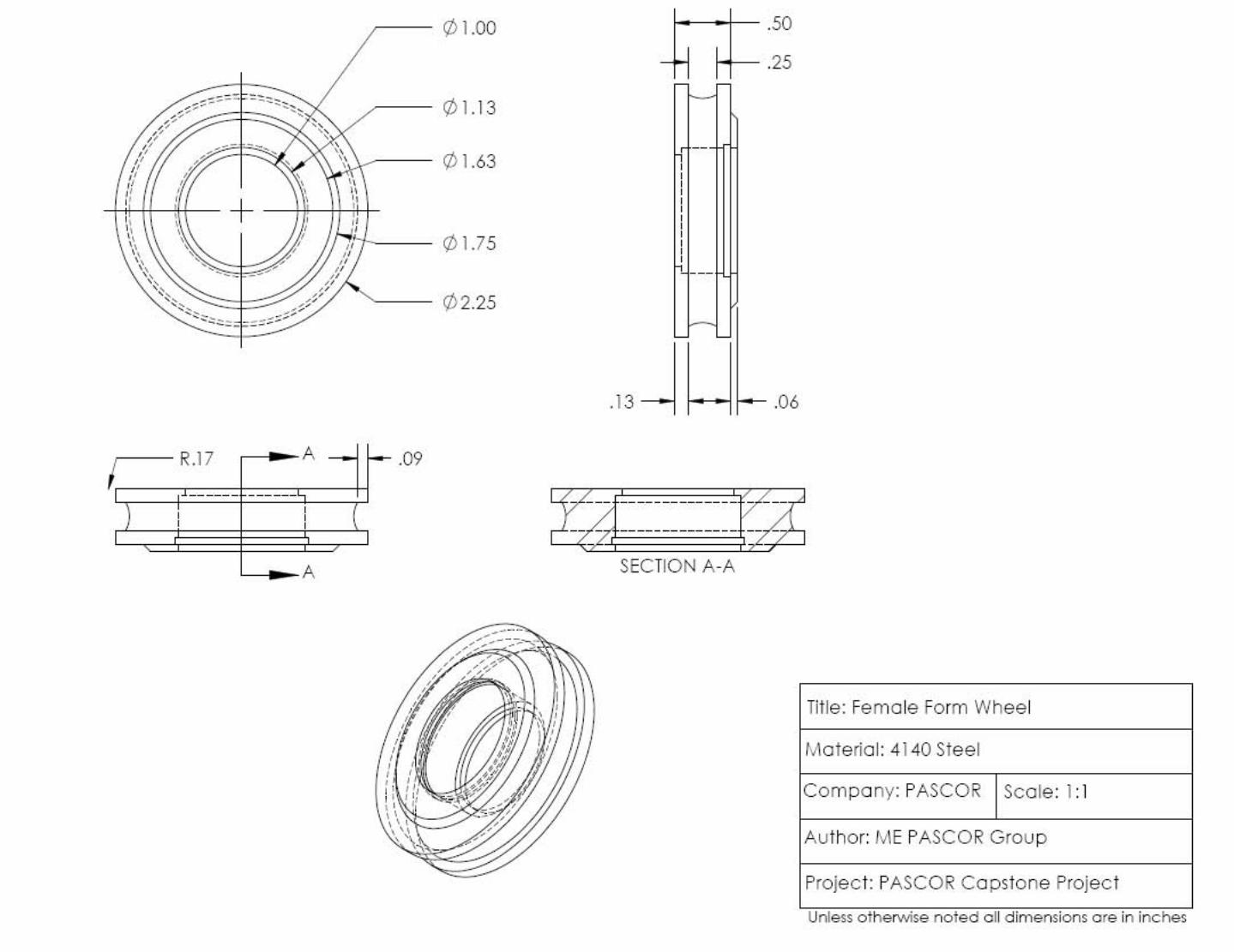
set screws. A female form wheel was designed to have a 2.25 in outside diameter and a
concave radius cut of 0.17 in into the wheel. The female wheel has a bearing pressed into
the wheel with an internal snap ring holding the bearing in place. This assembly was
placed onto a hardened shaft of 60 Rockwell C and was used as an idler wheel. The silver
strip material is fed into the male and female forming wheel, cut to length, and then fed
out of the form wheels as a finished product. Figure 7 shows an exploded view of the
forming system.
Figure 7: Exploded view of forming system.
11
Feed System The feed system is responsible for pulling the silver from the spool, moving the
material through the guide and to the forming wheels. Figure 8 shows an exploded view
of the feed system. This system consists of 2 polyurethane feed wheels and an identical
motor as used in the forming system. The feed wheels, used for pulling the silver off the
spool holder, needed to be durable and have a high coefficient of friction. The wheels
chosen employed an aluminum core with a hardness of 80A Durometer where the
polyurethane compound poured onto outside of the aluminum and finished to a 2 in
diameter. Two set screws hold the bottom feed wheel onto the motor shaft. The top feed
wheel, featuring a bearing, will act as an idler wheel and be placed onto a shaft hardened
to 60 Rockwell and held in place with a nut.
Figure 8: Exploded view of feed system.
12
Cutting System The cutting system is used to cut the silver strip material swiftly and with minimal
deformation to the material. The cutting system employs the use of an air actuated
cylinder, regulator with gauge, electric-over-air solenoid, cylinder mounting bracket,
blade holder, and cutting blade. Figure 9 shows the exploded view of the cutting system.
From testing, it was found to take a force of 35 lb to cut the silver strip material. Based
on that information a 1.5 in diameter actuator with a 0.75 in stroke was chosen. The
actuator was equipped with a magnet inside for sensor detection. At 50 psi the actuator
can deliver approximately 75lbs of force, which can be maintained with the regulator.
The electric-over-air solenoid controls the air flow to the actuator. In its normal state the
solenoid allows for the air to fill the bottom chamber of the actuator resulting in the blade
to be in the up position. When the solenoid receives an electric signal it inverts the air
flow thus evacuating the lower chamber and filling the upper chamber, this results in the
cutting action. A bracket was fabricated to mount the actuator to the plate allowing for
vertical adjustment. The blade holder is bolted to the top of the actuator arm. Fabricated
out of 1018 steel, the blade holder was
designed to hold the blade and act as a
bottom guide for the silver. The last
piece on the cutting system is the angled
cutting blade made out of ¼ in thick
4140 steel. The blade edge was angled
to 15 degrees from horizontal and was
ground and sharpened. After
fabrication, the blade was hardened and
quench to 55 Rockwell for durability.
Figure 9: Exploded view of cutting system.
13
Guide System The guide is located between the feed and forming wheels and is responsible for
aligning the silver as the material travels between the two systems. Figure 10 shows the
features of the guide system. A slot is incorporated into the top guide acting as a channel
for the silver to move through and to restrain the silver from moving side to side.
Chamfers are built into the front of the slots in order to better divert the silver into the
slot. The front and back of both guides have a machined radius equivalent to the feed and
form wheels. This allows the guide to be extended closer to the point where the top and
bottom wheels make contact. The bottom guide is machined from 4140 steel and
hardened to a Rockwell C rating of 60 for increased strength, allowing the guide to act as
an opposing edge for the blade. Bolt slots are included on the bottom guide for vertical
adjustments.
Figure 10: Exploded view of guide parts.
14
Electronic System The electronic system consists of a programmable logic controller (PLC), power
supply, micro-step drivers, magnetic sensors, high-speed counter cards, 4-way selector
switch, and photoelectric sensors. The PLC was chosen based upon the number of inputs
and outputs, the ability to receive high-speed cards (to increase motor speed), and cost.
The PLC has 20 inputs and 16 outputs; more than what is currently used, leaving the
option to add more components to the design if needed. The PLC is the brain of the
system, which provides power to the sensors, receives inputs from the sensors, performs
basic logic functions, and controls outputs in the form of turning the motors and actuating
the cutter. The power supply feeds power through the micro-step drivers to the stepper
motors. The micro-step driver allows for the stepper motor to turn in fractions of a step,
delivering better precision of rotation, and processes the signals from the PLC. Two
magnetic sensors are placed on the air actuated cylinder to indicate when the cutter is in
the up or down position. High-speed counter cards work in parallel with the PLC
allowing for faster counter and timer functions; this allows step pulses to the motors at a
faster rate than what the PLC could normally produce, therefore increasing the rotational
velocity of the motors. A 4-way selector switch is used as an input to the PLC dictating
the length of the silver strip being generated. Each switch location is associated with one
of the four specified strip lengths. Photoelectric sensors are a type of digital proximity
sensor. The photoelectric sensor transmits a beam of light which when reflected off of a
surface at a specific distance is received by the sensor. If the surface is further away than
the focus length of the beam when the light is reflected off of the surface the reflection
will miss the sensor. This sensor is used to detect the presence of the silver strip in order
to know when the spool has run out.
Evaluations and Future Considerations A prototype of the system was constructed and tested. PDS requirements along
with assembly procedure were taken into account during evaluation. The following
sections cover the systems mentioned previously and describe particular elements of the
designs that may affect performance.
15
Spool Holder The spool holder fulfills the requirements of securely holding the silver and
remaining light weight. The malleable plastic allows the silver to roll off the spool
without causing deformation. The side walls fit tightly against the spool, preventing the
silver from binding or springing off the sides. During testing the silver caused minor
scratches on the plastic sides. Although this is expected, prolonged running times might
require repair or replacement of the plastic ahead of the scheduled maintenance dates.
Using a higher quality plastic that is harder with a lower friction coefficient would be a
solution if a problem arises.
Forming System The form system met the required 0.25 in radius but the length curvature was
somewhat sporadic. This could possibly be fixed by using tighter tolerances in the
manufacturing of the form wheels. The heat treatment process may have caused
inconsistencies in the geometry of the wheels resulting in miscellaneous anomalies in the
length curvature. It may have been better to make the form wheels out of tool steel for
better durability and hardness. Tool steels naturally have a higher hardness so the
deformation from heat treating is minimized.
Feed System The feed system meets all the requirements needed to pull the silver off the spool
holder and push it through the guide plate and into the form wheels. The feed wheels may
need to be replaced periodically due to normal wear.
Cutting System The cutting system performs superbly. The cutting action was swift, left clean edges,
and functioned efficiently. The blade will eventually need sharpening but the life of the
blade should last for many years due to the softness of the material being cut.
16
Guide System The guide system performed as expected. The upper plate allowed the necessary
lateral movement to align the silver into the form wheels. Although the lower mounting
plate cracked in one place near a tapped hole and broke at a mounting slot, this did not
reduce the performance of the system as a whole. As a possible solution to the cracking
issue, the guide could be tempered post heat treatment in order to decrease brittleness.
Electronic System The electronic system functions as expected with the exception of the high-speed
cards. The high-speed cards required further programming at a level beyond the group’s
abilities and were thus unused. Without the high-speed cards the system was still able to
control all of the processes but resulted in a slower rotational speed of the motors. Due to
the slower motor speed the target of one piece per second could not be realized. If given
more time and technical training in the use of the high-speed cards it is believed that the
design would have no problem meeting the piece per second target. The selector switch
functions properly in changing the lengths of the parts but further time adjustments are
required in order to get the lengths within tolerance.
Conclusion Following the completion of the prototype, our team is very pleased with success
of our machine. The silver strip cutting and forming device fulfilled the majority of our
targets. The machine is fully automated, with all four length programs installed and
working. The 2 inch length program has been calibrated and is cutting within 1/32 of an
inch per piece. The 3, 5, and 6.5 inch lengths are working but are not calibrated within
tolerance in order to save material, per our industry advisors request. Unfortunately the
team was unable to program the speed control cards to work properly; therefore we did
not meet the target of one part per second. Currently the machine is producing the 2 inch
lengths at 1.9 seconds a piece and approximately 5 seconds per piece for the 6.5 inch
lengths. Aside from missing the part per time target the machine was able to achieve
17
several other targets such as radius curvature, length curvature, over all weight,
reliability, cost and most other design specifications.
Based on the evaluation of the machines preliminary performance the team feels
that, with some further experience or instruction on speed control cards, the machine
would be capable of achieving the timing target; provided there are no unforeseen issues
associated with running the machine at faster speeds. If given the opportunity to improve
on the current design the team feels that the majority of the clearance and tolerance issues
could be eliminated and improved.
References [1]: Joseph Edward Shigley, Mechanical Engineering Design, 5th Edition, McGraw Hill, 2002, pp. 328-349 [2]: Groover, Mikell P. “Fundamentals of Modern Manufacturing Second Edition” John Wiley and Sons, Inc. Hoboken, NJ. 2002. [3]: All components for air cutting system ordered through Buchanan Automation Inc.: http://www.buchanan-a.com/hsr@@6.hsm [4]: All electronics ordered through AutomationDirect.com http://automationdirect.com
Acknowledgements Special thanks go out to Mike Flaman at PCC for manufacturing multiple
components as well as hardening specific parts. Thanks to Shawn Dunigan from ABC
Electric for PLC programming assistance. Thanks to Pacific Machinery and Tool Steel
for donating material to the senior project.
18
Appendices
Appendix A: Manufacturing and Assembly Overview
The overall assembly is broken up into sub-assemblies. Each sub-assembly
describes the manufacturing process used and the assembly process and requirements.
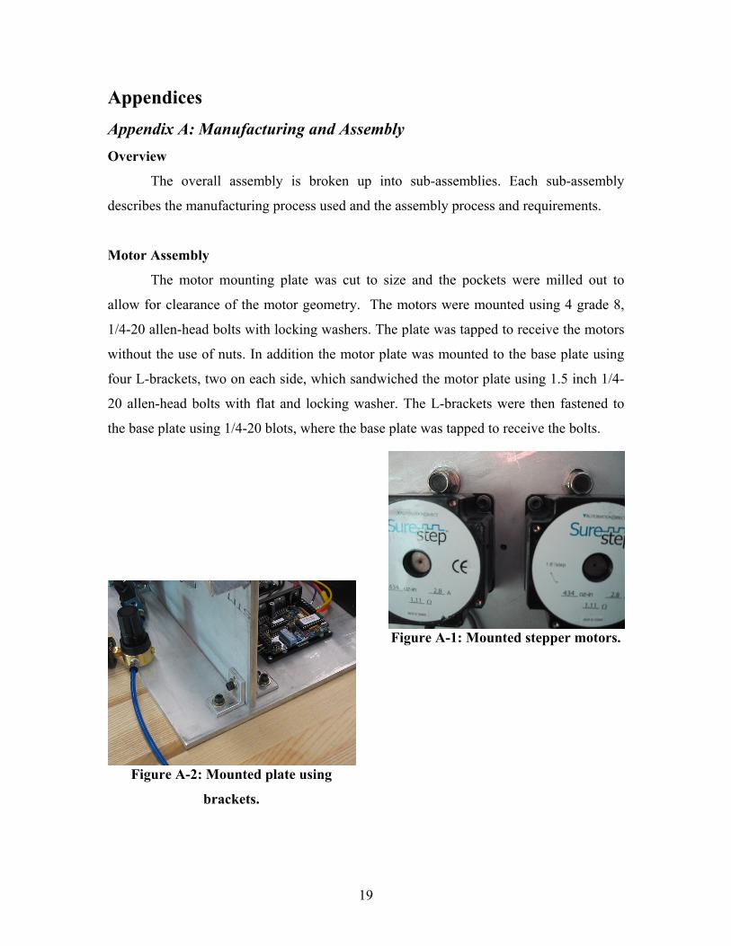
Motor Assembly
The motor mounting plate was cut to size and the pockets were milled out to
allow for clearance of the motor geometry. The motors were mounted using 4 grade 8,
1/4-20 allen-head bolts with locking washers. The plate was tapped to receive the motors
without the use of nuts. In addition the motor plate was mounted to the base plate using
four L-brackets, two on each side, which sandwiched the motor plate using 1.5 inch 1/4-
20 allen-head bolts with flat and locking washer. The L-brackets were then fastened to
the base plate using 1/4-20 blots, where the base plate was tapped to receive the bolts.
Figure A-1: Mounted stepper motors.
Figure A-2: Mounted plate using
brackets.
19
Wheel Assemblies
Each set of wheels consisted of and idler wheel and a direct mount wheel. The
idler feed wheel had a bearing pressed into the center hub. The idler form wheel was
manufactured on a CNC lathe and had a bearing pressed into the center hub which is held
by a snap ring. Both idler
wheels were secured to the
idler shafts with 1/2-20
locking nuts and the shafts
were mounted to the motor
plate also using 1/2-20
locking nuts. The feed and
form direct mount wheels
were secured to the motor
shafts using 2, 10-24 set
screws. Figure A-3: Feed wheels. Figure A-4: Form wheels.
Guide Assembly
The bottom portion of the two piece guide assembly was mounted to the motor
plate using 3, 1/4-20 allen-head bolts, where the plate was tapped to receive the bolts.
The top portion of the guide assembly had a slot end-milled to allow for the silver
stripping to pass through. The top guide portion was bolted to the bottom guide with 10-
24 bolts using lock washers, where the
top guide had slots milled for
adjustability and the bottom guide had
tapped holes to receive the bolts. In
addition the top and bottom portions of
the guide were milled to allow for
clearance with the wheels. Also both
portions had rectangular slots milled to
allow for the blade/blade holder to pass
through. Figure A-5: Mounted guides.
20
Cylinder/Blade Mounting
The cylinder was fastened to the mounting bracket using 10-24 allen-head bolts,
where the cylinder had tapped holes to receive the bolts. The mounting bracket had slots
milled to allow for adjustability and it was
bolted to the motor plate with 10-24 allen-head
bolts with locking washers, where the motor
plate was tapped to receive the bolts. In
addition the blade holder was manufactured on
a mill and was mounted to the cylinder piston-
rod mounting bracket with 2, 1/4-20 allen-head
bolts where the mounting bracket was tapped
to receive the bolts. The blade was
manufactured on a mill and heat treated to the desired hardness. Also the blade was
attached to the blade holder with 2, 1/4-20 counter-sunk allen-head bolts, where the
holder was tapped to receive the bolts.
Spool Stand and Spool Holder
The spool holder was made of plastic where the pieces were cut out of a sheet
with a jig saw and then brought to final dimensions with a file. The spool was assembled
and mounted to the spool holder. The
spool holder was cut to length with a
hack saw and the mounting holes were
drilled to 1/4 diameter. The holder
itself was mounted to the base plate
with two L-brackets where 2, 1/4-20
allen-head bolts sandwiched them
together and 2, 1/4-20 allen-head bolts
fastened the L-brackets to the base
plate.
Figure A-6: Linear actuator.
Figure A-7: Spool mounted with brackets.
21
Electronics
The PLC, micro-stepper drives and the power supply were mounted to the base
plate using #4 and #8 machine screws. The majority of the electronics were wired
following the manufacturer’s instructions, as seen in the figure below. The magnetic
sensors were wired per the instructions included in the packaging. The air solenoid was
incorrectly wired to the DC negative terminal, but was quickly rectified when we realized
it was not working. The pneumatic lines were then connected to the cylinder, following
the schematic that accompanied the solenoid.
Figure A-8: Motor wiring diagram.
Figure A-9: Finished wiring.
22
Table A-1: Complete part system with name and description.
Name: Flat Bar System: Spool Holder Description: The bar is constructed from 1018 steel and is used as the stand to support the silver spool.
Name: Bar Bracket System: Spool Holder Description: The bracket made of 6061-T6 aluminum, attaches the bar securely to the base plat.
Name: Side Wall System: Spool Holder Description: Plastic side wall used for holding the silver spool.
Name: Center Roll System: Spool Holder Description: Plastic center that the silver spool overlays.
Name: Center Bearing System: Spool Holder Description: ¼ in ID sealed bearing located in the center roll.
Name: Spool Bolt System: Spool Holder Description: Grade 8 bolt with shoulder used to support silver spool.
23
Name: Plate System: Plate Description: Center plate made of 3/8 in 6061-T6 aluminum.
Name: Plate Bracket System: Plate Description: 6061-T6 aluminum bracket used to mount plate to base.
Name: Motor System: Form and feed Description: Stepper motor used to drive the forming and feed system.
Name: Idler Form Wheel (Female) System: Forming Description: Female wheel made from 4140 steel used to form silver.
Name: Form Wheel (Male) System: Forming Description: Male wheel made from 4140 steel used to form silver.
Name: Idler Shaft System: Form and feed Description: Shaft made from 4140 steel used for idler wheels.
Name: Idler Bearing System: Form and feed Description: ½ in ID sealed bearing used in the form and feed idler wheels.
24
Name: Idler Feed Wheel System: Feed Description: Wheel made from polyurethane used to pull the silver from the spool holder and feed to the form wheels. Name: Feed Wheel (Driver) System: Feed Description: Wheel made from polyurethane used to pull the silver from the spool holder and feed to the form wheels.
Name: Actuator System: Cutting Description: Linear actuator power by compressed air.
Name: Blade Holder System: Cutting Description: Holder constructed of 1018 steel, used to secure the blade and attach to the actuator.
Name: Blade
System: Cutting Description: Silver cutting blade machined from 4140 steel.
Name: Actuator Base System: Cutting Description: Base made from 6061-T6 aluminum used to secure the actuator and mount to the plate. Name: Top Guide System: Guide Description: Machined from 4041 steel and used to guide the silver from the feed wheels to forming wheels.
25
Name: Bottom Guide System: Guide Description: Machined from 4041 steel and used to guide the silver from the feed wheels to forming wheels.
Appendix B: Bill of Materials Table B-1: Complete bill of materials with final cost.
Appendix C: Operation Manual 1. Feed silver through feed wheels and guide so that the edge of the silver is just
barely protruding out of the guide in the cutting area.
2. Plug power cable into a properly grounded 120VAC 15Amp power outlet.
3. Connect air hose to minimum 80psig supply line.
4. Put switch on PLC to Run Mode.
5. Turn selector dial to desired length setting.
6. Press the Start button.
7. When stopping the machine press the stop button during the half second after a
cut, before the feed wheels start to move.
Appendix D: Calculations Spool Holder
Summary The object of this analysis is to determine the safety factor of the spool holder.
The analysis specifically focuses on the bolt failure and bar bearing and tearout failure. Since the feed wheels continually remove silver from the holder, a constant force is transmitted to the spool holder system through the silver.
Schematics:
Free body diagram of bar.
27
Given: The data below represents the defined bar and bolt dimensions and properties
required to solve the design problem.
• Tmax = 27.125 in*lb Maximum motor torque • Dbolt = 0.25 in Bolt diameter • Abolt = 0.049 in² Bolt area • Dwheel = 2 in Wheel Diameter • Sybolt = 130000 psi Bolt yield strength • tbar = 0.25 in Bar thickness • wbar = 1 in Bar width • Sybar = 53700 psi Bar yield strength • h1 = 0.625 in Distance between bracket bolts • h2 = 7.75 in Distance from top bracket bolt to spool bolt
Find:
• Find the safety factor against bolt failure, bearing failure, and tearout. Assumptions:
• The spool roll with bearing seizes, no longer freely rotating or allowing the silver to spin off the spool.
• The inside of the silver spool does not slip on the outside of the roll. • The silver stripping is rigid, with no deformation. • The motor applies the maximum amount of force possible. • Friction between the bar and brackets is insignificant.
Solution: The horizontal force produced by the motor and transmitted to the spool by the silver is shown below:
lbD
TF
wheelhor 125.27
2/2125.27
2/max ===
Using a combination of summation of forces and moments the two reaction forces at the bracket are R1 and R2, where R1 is the force at the lower bolt and R2 is the force at the upper bolt.
lbhhh
R hor 35.336625.075.7*
1
21 ===
lbRFR hor 475.36335.336125.2712 =+=+=
Since each bolt is in double shear, a factor of 2 is added to the equations below. τ1 and τ2 represent the shear stress of the lower and upper bolt respectively.
28
psiA
R
bolt
3426049.0*235.336
*21
1 ===τ
psiA
R
bolt
3702049.0*2475.363
*22
2 ===τ
Using distortion energy equation from [1] and analyzing the bracket bolts for failure, the safety factor at the lower and upper bolts are 21.9 and 20.3 respectively.
9.213426
130000*577.0*577.0
11 ===
τboltSy
n
3.203702
130000*577.0*577.0
22 ===
τboltSy
n
The bearing area calculated below is used to determine the safety factors for direct bearing failure.
2063.025.0*25.0* intDA barboltbearing === The bearing stress on the lower bolt is σ1 and the bearing stress on the upper bolt is σ2, shown below:
psiA
R
bearing
5382063.0
35.33611 ===σ
22
363.475 58160.063bearing
R psiA
σ = = =
The safety factors for direct bearing stress on the bar is 10.0 for the lower bolt hole and 9.2 for the upper bolt hole.
11
53700 10.05382
barSynσ
= = =
22
53700 9.25816
barSynσ
= = =
The tearout area to determine bolt tearout on the lower bar holes is shown below:
The tearout shear stress is calculated for the lower bolt holes where τ1 and τ2 are the lower and upper bolt holes respectively.
11
336.35 17940.187tearout
R psiA
τ = = =
2
2363.475 19390.187tearout
R psiA
τ = = =
The safety factors against bar tearout is 17.3 and 16.0 for the lower and upper bolt holes respectively.
11
0.577 * 0.577 *53700 17.31794
barSynτ
= = =
22
0.577 * 0.577 *53700 16.01939
barSynτ
= = =
References: [1]: Joseph Edward Shigley, Mechanical Engineering Design, 5th Edition, McGraw Hill, 2002.
30
Forming/Feed Shafts
Summary The object of this analysis is to determine the factor of safety against fatigue
failure of the idler shaft. The shaft continuously takes on alternating forces and cumulative stressed over time may lead to fatigue damage. Schematics:
Free body diagram of idler shaft.
Given:
The data below represents the defined shaft dimensions and properties required to solve the design problem.
• Dbolt = 0.5 in Bolt diameter • Abolt = 0.1419 in² Tensile area of bolt • cb = 0.25 in Distance to centroidal axis of bolt • Sut = 150000 psi Tensile strength of bolt • Sproof = 120000 psi Proof strength of bolt • Tavg = 13.6 in*lb Average torque require to form silver • Lc = 0.125 in Measured contact length of wheel on material • µb = 0.15 Assumed friction of bolt on plate • Lshaft = 1 in Shaft length • wwheel = 0.375 in Width of wheel
Find:
• Find the safety factor against fatigue failure of the idler shaft. Assumptions:
• Twice the force needed to resist vertical shaft movement on the plate is acceptable.
31
• Minimum stress is a constant axial shaft stress. Maximum stress is the combination of axial stress and bending stress.
Solution: The axial force needed to prevent the shaft from vertical movement is:
108.8 725.30.15
sepaxial
b
FF lb
μ= = =
Assuming a safety factor of two to resist sliding on the plate, the required total axial force is:
2* 2*725.3 1451total axialF F= = = lb Using the total force above, the equivalent axial stress on the shaft is:
1451 73880.1419
totalaxial
bolt
F psiA
σ = = =
The vertical separation force calculated from the average torque is shown below. Lc was measured from experimental results.
13.6 108.80.125
avgsep
c
TF lb
L= = =
The second moment of area of the bolt is:
4 44* *0.5 0.003068
64 64bolt
bDI iπ π
= = = n
Using the shaft length, wheel width, centroidal axis distance, and second moment of area, the bending stress on the shaft is:
* * 108.8*0.8125*0.25 72030.003068
sep M bbending
b
F L cpsi
Iσ = = =
Adding the axial and bending stresses together result in a maximum stress of:
max 7388 7203 14590axial bending psiσ σ σ= + = + = The minimum stress is a constant axial stress of:
32
min 7388axial psiσ σ= = Using the minimum and maximum stresses, the mean and alternating component stresses are σm and σa respectively.
max min 14950 7388 109902 2m psiσ σσ + +
= = =
max min 14950 7388 3602
2 2a psiσ σσ − −= = =
In order to find the fatigue strength an endurance limit analysis must be completed. Starting with the endurance limit of a test specimen, the value is:
' 0.504* 0.504*150000 75600utSe S psi= = = Surface finish constants of a = 2.70 and b = -0.265 for a machined surface from [1] lead to a surface finish factor of 0.115 as shown below
0.265* 2.70*150000 0.115ba utk a S −= = =
Finding the equivalent size factor for the shaft produces a value of 0.944 below
0.1133 0.11330.5 0.9440.3 0.3
boltb
Dk− −
⎛ ⎞ ⎛ ⎞= = =⎜ ⎟ ⎜ ⎟⎝ ⎠ ⎝ ⎠
The load factor from [1] is kc = 0.923 for shear and torsion. The final endurance limit is a combination of the test specimen and the above factors leading to a value of 7556 psi.
'* * * 75600*0.115*0.944 *0.923 7556a b cSe Se k k k psi= = = Using the modified Goodman equation the fatigue safety factor for the shaft is 1.8.
1 1 1.8183602 109907556 150000
a m
ut
n
Se Sσ σ= = =
+ +
References: [1]: Joseph Edward Shigley, Mechanical Engineering Design, 5th Edition, McGraw Hill, 2002.
33
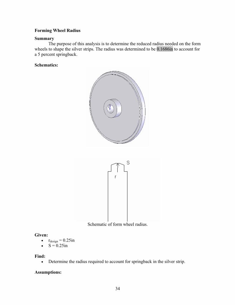
Forming Wheel Radius
Summary The purpose of this analysis is to determine the reduced radius needed on the form wheels to shape the silver strips. The radius was determined to be 0.1686in to account for a 5 percent springback.
Schematics:
Schematic of form wheel radius.
Given:
• rdesign = 0.25in • S = 0.25in
Find:
• Determine the radius required to account for springback in the silver strip. Assumptions:
34
• Width of formed strip reduced by 5 percent. Solution: Determine the angle given the arc length and design radius:
°=−
=−
=
°=°
===
35.612
3.571802
180
3.57180*125.025.0
θα
πθ rad
rS
design
Use Law of Sines to determine width of formed strip:
ininrx 23973.0)35.61sin(
)3.57sin(*25.0)sin(
)sin(*=
°°
==αθ
Determine reduced width:
ininxx 22774.023973.0*95.0*95.0' === Use Law of Cosines to determine new radius:
inrr
rrin
rrrrxrr
S
1686.0
)25.0cos(**2*2)22773.0(
)cos(***2)'(
25.0
222
222
=
−=
−+=
==
θ
θ
35
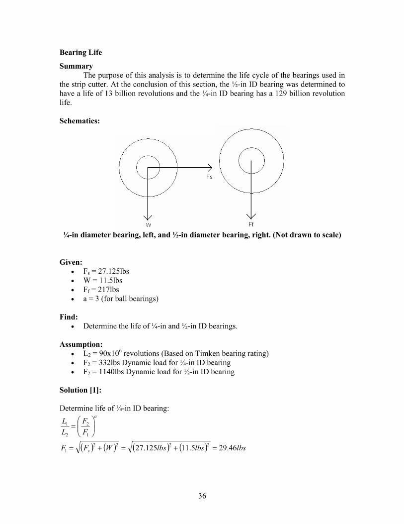
Bearing Life
Summary The purpose of this analysis is to determine the life cycle of the bearings used in the strip cutter. At the conclusion of this section, the ½-in ID bearing was determined to have a life of 13 billion revolutions and the ¼-in ID bearing has a 129 billion revolution life. Schematics:
¼-in diameter bearing, left, and ½-in diameter bearing, right. (Not drawn to scale)
Given: • Fs = 27.125lbs • W = 11.5lbs • Ff = 217lbs • a = 3 (for ball bearings)
Find:
• Determine the life of ¼-in and ½-in ID bearings. Assumption:
• L2 = 90x106 revolutions (Based on Timken bearing rating) • F2 = 332lbs Dynamic load for ¼-in ID bearing • F2 = 1140lbs Dynamic load for ½-in ID bearing
Solution [1]: Determine life of ¼-in ID bearing:
( ) ( ) ( ) ( ) lbslbslbsWFF
FF
LL
s
a
46.295.11125.27 22221
1
2
2
1
=+=+=
⎟⎟⎠
⎞⎜⎜⎝
⎛=
36
srevolutionlbs
lbsFFLL
a9
36
1
221 10*8.128
46.29332*10*90* =⎟
⎠⎞
⎜⎝⎛=⎟⎟
⎠
⎞⎜⎜⎝
⎛=
Determine life for ½-in ID bearing:
srevolutionlbslbs
FFLL
a9
36
1
221 10*13
2171140*10*90* =⎟
⎠⎞
⎜⎝⎛=⎟⎟
⎠
⎞⎜⎜⎝
⎛=
Conclusion: Both bearings should exceed the life of the machine. References: [1]: Joseph Edward Shigley, Mechanical Engineering Design, 5th Edition, McGraw Hill, 2002, pp. 455-456
37
Motor Plate/Mounting Bracket
Summary: The object of this analysis is to determine the factor of safety of the bolts supporting the mounting plate to the l-brackets. For ease of manufacture, 0.25-in bolts were used in this joint. Schematics:
The result of this analysis is a factor of safety of 146. This shows that this joint is clearly over designed, but reduces the number of different sizes of bolts in the device. The preload for the bolts corresponds to a torque of 17.9 lb-ft.
Free body diagram of plate, bolts, and other components.
38
Given:
• Feed wheel diameter = 2in • Form wheel diameter = 2in • Feed and form wheel thickness = 0.5in • Plate size = 12in x 12in x0.375in • Wm = 3.85lbs • Sut = 150ksi for grade 8 bolt • Sy = 130ksi • Sp = 120ksi • At = 0.0318in2 for ¼-20 UNC bolt • ρAl = 0.098lb/in3 • ρSt = 0.282lb/in3
Find:
• Determine the factor of safety in shear of the mounting bolts. Assumptions:
• Feed wheels made of solid aluminum. • Form wheels made of solid steel. • Bolts are in double shear. • Bolts are to be in a reused connection (Fi = 0.75*Fp).
Solution: Weight of feed wheel:
lbsinininlbdtW Al 154.04
)2(**5.0*/098.04***
23
2
===ππρ
Weight of form wheel:
lbsinininlbdtW St 443.04
)2(**5.0*/282.04***
23
2
===ππρ
Weight of plate:
lbsininininlbthwW Alp 29.5375.0*12*12*/098.0*** 3 === ρ Weight of feed wheels, form wheels, motors, and plate:
lbslbslbslbslbsWWWWW mformfeedpt 2.1485.3*2443.0*2154.0*229.5*2*2*21 =+++=+++= Since weight of pneumatic cylinder is not known, assume a total weight of 20lbs:
lbsWT 20= Stresses due to direct shear per bolt:
39
psiin
lbsA
W
t
T 5.3140318.0*2
20*2 2 ===τ
Factor of safety per bolt in double shear:
7.2065.314*2
130000*2
===psi
psiSFS Y
τ
Preload on bolt:
lbslbsFF
lbspsiinSAF
pi
ptp
28623816*75.0*75.0
3816120000*0318.0* 2
===
===
Torque required to load bolt to preload:
ftlbinlbinlbsdFKT i ⋅=⋅=== 9.177.21425.0*2862*30.0** Conclusion: The bolt design is clearly acceptable, although over designed. References: [1]: Joseph Edward Shigley, Mechanical Engineering Design, 5th Edition, McGraw Hill, 2002, pp. 455-456
40
Motor Plate/Mounting Bracket
Summary:
The purpose of this analysis is to determine the grade and fatigue safety factor of the motor mounting bolts as well as a check against joint separation of the motor and mounting plate. Each motor uses four mounting bolts which are subjected to a combination of shear and axial forces. In addition the motor mounting holes are 0.26 in thru holes therefore requiring ¼ in bolts. Schematic:
Given:
• Max Torque (due to forming): Tmax = 27.125 in-lbf • Separation Force (due to forming): Fform = 108.8 lbf • Motor Weight (total): Wmotor = 4.3 lbf • Motor Shaft to Bolt Distance: r = 1.94 in • Forming Force to Moment Reaction Distance: dMR = 1.37 in • Tensile Stress Area (for 0.25 inch bolt): At = 0.0318 in2 • Major-Diameter Area (for 0.25 inch bolt): Ad = 0.0491 in2 • Proof Strength (grade 8): Sp = 120 ksi • Yield Strength (grade 8): Sy = 130 ksi • Ultimate Strength (grade 8): Sut = 150 ksi • Modulus of Elasticity (steel bolt): Eb = 30 X 106 psi • Modulus of Elasticity (aluminum motor and mounting plate): Em = 10.3 X 10⁶ psi
Find:
• Determine fatigue factor of safety and possibility of joint separation. Assumptions:
• Based the calculations on the bolt that had the maximum resultant force. Solution: Shear Force/Stress Calculations: The total shear force is made up of the shear force due to the weight (primary shear or direct load) of the motors plus the shear force due to the torque applied (secondary shear or moment load) by the stepper motor. The maximum resultant shear force was determined using the parallelogram rule.
Therefore the maximum shear stress, based on the tensile-stress bolt area, is:
psiin
lbfAF
t
RMax 35.966
0318.073.30
2 ===τ
Also the minimum shear stress, without motor torque input, is:
psiin
lbfA
W
t
motorMin 27.30
0318.0*485.3
4 2 ===τ
Axial Force/Stress Calculations: The total axial force on the bolts consists of the force from the preload on the bolt and the force from the bending moment caused by the forming action. Axial reaction force on one top bolt:
lbfin
lbfd
FF
MR
formMR 71.39
37.1*28.108
2===
Pre-load based on reused bolt connection:
lbfksiinSAF pti 2862120*0318.0*75.0**75.0 2 === Therefore the maximum axial stress, based on the tensile-stress bolt area, is:
( ) ( ) psiin
lbfA
FF
t
iMRMax 249,91
0318.0286271.39
2 =+
=+
=σ
Also the minimum axial stress, without forming stress, is:
psiin
lbfAF
t
iMin 000,90
0318.02862
2 ===σ
42
Von Mises, Amplitude and Mean Stress Calculations: The maximum and minimum Von Mises stress values are use to combine the axial and shear stresses values to determine the amplitude and mean alternating stresses.
psipsipsiMaxMaxMax 264,9135.966*3249,913' 2222 =+=+= τσσ (Max Von Mises)
psipsipsiMinMinMin 000,9027.30*3000,903' 2222 =+=+= τσσ (Min Von Mises)
psiMinMaxM 632,90
2''
=+
=σσ
σ (Mean Alternating Stress)
psiMinMaxA 632
2''
=−
=σσ
σ (Amplitude Alternating Stress)
Endurance Limit Calculations: The fully corrected endurance limit is based on the uncorrected endurance limit and modifying factors such as surface, size and load factors. All endurance-limit modifying factors: Shigley, Mechanical Engineering Design text:
buta Sak *= Where, a = 2.70 and b = -0.265, for Machined or Cold-Drawn materials
716.0150*70.2 265.0 == −
ak (Surface Finish Factor for Sut in ksi)
102.13.0
25.03.0
1133.01133.0
⇒=⎟⎠⎞
⎜⎝⎛=⎟
⎠⎞
⎜⎝⎛=
−−dkb (Size Factor for inches)
923.0=ck (Load Factor for Axial Loading since Axial Loading is Dominate Load)
Therefore, ksiksiSkkkS ecbae 96.496.75*923.0*1*716.0' === Fatigue Life Safety Factor Calculation: The fatigue safety factor is based on the Goodman equation.
62.1150
632.9096.49
632.01=⇒+=+= n
ksiksi
ksiksi
SSn ut
M
e
A σσ
Load Factor Calculations: The load factor, guarding against joint separation, is calculated based on the pre-load and applied load of the bolt as well as the joint constant. The joint constant is dependant on the bolt stiffness and the joining member stiffness.
43
The bolt stiffness is:
dttd
btdb lAlA
EAAk
+=
inindlt 75.025.02 =+= (Threaded Portion of Bolt, where d = 0.25 in) inld 40.0= (Unthreaded Portion of Bolt)
Based on the joint constant and the loads, the load factor is:
( ) ( ) 7.35284.018.108
28621
=−
=−
=lbf
lbfCF
Fn
form
iseparation
Based on the calculations the motor bolts have a fatigue factor of safety of about 1.62 with a pre-load of about 2862 lbf, which gives a load factor of about 35.7 against joint separation.
References: [1]: Joseph Edward Shigley, Mechanical Engineering Design, 5th Edition, McGraw Hill, 2002.
44
Cutting Force Requirements
Summary: The purpose of this analysis was to select the appropriate
pneumatic cylinder for the cutting operation. The thrust (cutting force) of the cylinder is based on the cross sectional area of the cylinder-piston. The cylinder is comprised of a major and a minor cross sectional area. The major area is based on the maximum cylinder area and the minor area is based on the maximum cylinder area minus the total piston-rod area. Given:
• Assume cutting will use minor area and air pressure is constant. Solution:
or
cuttingair A
FP
min
=
( ) ( )( ) ( ) ( )( ) 22222min 54.138.0*25.1
4*2
4inddA rcpcor =⎥⎦
⎤⎢⎣⎡ −=⎥⎦
⎤⎢⎣⎡ −= −−
ππ
psiinlbfPair 3.28
54.16.43
2 ≥=
Therefore, the minimum air pressure needed to perform the cutting is about 30 psi for the 1.5 inch diameter pneumatic cylinder.
45
Appendix E: Experimental Data and Results Summary
The following report discusses the experiments performed in order to obtain values for cutting force and torque and pressing force for the two forming methods. These values were crucial to the progression of the design process. With the values determined the group was then able to proceed in researching the required components that could deliver the needed forces. Introduction
The purpose of this project was to determine the forces required to cut and form silver stripping. The results were used to assist the senior capstone design team in choosing a final design concept. The sponsoring company for the capstone project, Pacific Air Switch Corporation (PASCOR), receives spools of silver that are ¼ inch wide. PASCOR has requested that the silver be cut in variable length strips, and the width be bent with a ½ inch diameter curvature. Figure 1 shows the dimensions that PASCOR has requested. The silver strip lengths have a tolerance of 1/16 inch, but the tolerance is irrelevant to the experiments in this report. The shearing (cutting) and bending (forming) forces are the crucial information.
Figure E-1: Dimension requirements provided by PASCOR.
This report consists of three separate experiments involving cutting, press
forming, and roll forming of the silver stripping. The cutting experiment found and compared the forces required to shear the silver strips from two separate blades with different rake angles. The press and roll forming experiments, each with different methods, were performed to determine the forces required to form the silver stripping to the required curvature. The press forming method tested for the minimum force required to form an entire silver strip at one time, while the rolling method tested for the minimum force (from torque) to roll a silver strip. To maintain control of our experiments we used calibrated equipment, when available, and calibrated other equipment based on manufacture specifications. In addition, the results from all three tests were compared to theoretical values to determine the accuracy of measurement devices. Populating standard deviation was used to verify if the values were acceptable for PASCOR’s requirements.
46
Theory
Tekscan Flexiforce load sensors can be used to measure applied loads, changes in loads, and identify force thresholds and trigger appropriate action. As a load is applied to the sensor, the internal resistance decreases, creating a voltage differential that can be measured. When unloaded, a multimeter will record about 1 MΩ, and when loaded about 20 kΩ. A Flexiforce sensor is used with one pin connected to the negative voltage output of an operational amplifier and the other pin to approximately -5V. A feedback loop is wired from the negative op amp output through a feedback resistor of minimum 1 kΩ. A voltage is measured between the feedback and the ground and will show a linear relationship with the force applied.
Since a linear relationship exists between force (weight) and voltage, the voltage produced by a calibrated load sensor can be converted to an applied load. The linear calibration conversion for this experiment was determined to be:
y 22.781x⋅ 3.9738−:= (1) Where y is the output mass in kilograms and x is the input voltage in volts. In addition a simple conversion was used to convert the mass, in kilograms, to a pound force result. Equation (1) was used to produce the experimental result and the data used to formulate the equation is shown in the result section in figure 13.
Shearing of plate and sheet metal is a popular and effective method for producing products. The same concept was used, but experimentally feasible on a smaller scale of operation. The tensile strength of the 85% silver 15% nickel alloy along with the silver strip dimensions were needed in order to calculate the maximum shear force. By knowing the tensile strength of a given material, the shear strength is typically and was approximated as 70% of the tensile strength. The force needed to shear a beam is found by equation (2) (Groover, 2001)
Fcut Ss tsilver⋅ Lcut⋅:= (2) where Ss is the shear strength and the cross sectional shear area shown in figure 2 is defined by the thickness of the silver (tsilver) multiplied by the width of the silver (Lcut).
Figure E-2: Cross sectional shear area showing width and thickness in inches.
Equation (2) predicts the maximum shear force, which involves a flat blade that contacts the entire surface at the same time. For this experiment, the maximum cutting force for a flat blade was compared to the cutting forces with a blade machined with a 15 degree angle as shown in figure 6. For known material data and blade properties, equation (3) from the Society of Manufacturing Engineers (SME) is,
F6 S⋅ T2⋅ P2⋅
R:=
(3) where, F is the shear force in lb, S is the material shear strength in lb/in², T is the material thickness in inches, P is the blade penetration in percentage, and R is the rake angle in
47
inches/foot. The penetration percentage was not available for the silver-nickel used in this experiment; therefore the theoretical shearing forces for the angled cutter were not calculated for comparison. Two forming process experiments were conducted in order to compare the amount of force required to form the silver strips to the required width curvature. The first experiment used a press forming operation, in which an entire piece of silver was formed at one time with one action. The total force required to press form silver strips is given in equation (4),
Fkbf TS⋅ w⋅ t2⋅
Ddie:=
(4) where kbf is a unitless bending constant, TS is tensile strength in lb/in², w is width of the material along the bend axis in inches, t is the thickness of the material in inches, and Ddie is the diameter of the press die. The bending constant, kbf, is 1.33 based on a v-bending operation. This value was experimentally determined, and is the best value available for the silver-nickel alloy used in this experiment. The die diameter is based upon the width of the silver strip after being formed to the appropriate curvature. The angle of bend is approximated by θ,
θ 360wC⋅:=
(5) Where 360 is a conversion from inches to degrees, w is width of the silver in inches, and C is the circumference of a circle in inches, based upon the curvature radius. Using triangle symmetry to find the other angle and the law of sines,
Ddiesin θ( )sin φ( ) Radius⋅:=
(6) where θ is the angle of bend in degrees, Ф, is the opposite angle in degrees, and radius is the curvature radius in inches, the die opening was calculated. For clarification, figure 3 shows how equation (5) relates to the press forming operation, where the bend angle, θ, the curvature radius, and the silver width (arc length) are shown. Figure 4 represents the die opening in equation (6).
Figure E-3: Bend angle representation Figure E-4: Die opening representation
The other forming operation consisted of rolling the silver with two rollers. Since the force required to form the silver is related to the rotational movement of the rollers, the measurement is in terms of the rotational force (torque) required to turn the wheel and silver. The equation (7), below,
48
F
Tr
:= (7)
relates the required linear force, F, in lbs, to the torque, T in inch-lbs and roller radius, r in inches. Figure 5 illustrates the linear force, F, needed to roll form the silver strip material.
Figure E-5: Representation of the force and rollers required to form the silver.
All of the experiments were performed numerous times to capture an accurate average. Based on the average values, for each experiment, the associated sample and population standard deviations were calculated as a measure of variance instead of measurement uncertainties. Excel was used to determine the standard deviations based on the following relationships:
Sample Standard Deviation (8)
Population Standard Deviation (9) Since the design project requires complete success in cutting and forming, a one-sided Z-table will be employed to ensure approximately 99.9% success. The following equation can be used to determine the required values to achieve the desired rate of success:
Z1
x1 x−
Sx:=
(10) Where, Z1 is given as 3.09, from any one-sided Z-table, which corresponds to a 99.9% success, Sx is the standard deviation, x is the mean value and x1 is minimum required value for the desired success. Methods and Apparatus
49
Load Cell To accurately measure forces with the load cell a simple fixture was used to
consistently apply loads to the load sensor. The fixture consisted of two, three inch, square plates and a nylon disc. The nylon disc has the same cross sectional area as the load sensor on the load cell. The load cell was taped to one of the plates with the load sensor centered and the nylon disk was glued to the center of the other plate. The centering of the load sensor and the nylon disk allowed for accurate force readings and is shown in figure 7.
A protoboard was used to supply voltage to an operational amplifier circuit containing the load cell. The load cell was conditioned by applying about 110% of the estimated maximum load with known weights. This was repeated a total of four times to ensure proper conditioning. After the load cell was conditioned it was calibrated. To calibrate the load cell, known loads were applied to the cell and corresponding voltages were recorded with a multimeter. Then a calibration curve was developed for the voltage and force relationships. Cutting Forces The required cutting force was measured using a 100 lb Flexiforce load cell. Two cutting blades were used during the experiment, one had a 15 degree rake angle and the other had a 0 degree rake angle. These two cutting blades shown in figure 6 were fabricated to fit into a small arbor press. The cutting blades were bolted to the bottom plate of the load cell fixture and the combination was then mounted to the arbor press as shown in figure 7.
Figure E-6: Picture of 15 degree and straight blade Figure E-7: Picture of Load Cell Fixture with cutters with dimensions. the load cell and cutter installed. An additional fixture was developed to hold the strips of silver, shown in Figure 8. The fixture consisted of a piece of channel with a milled out slot and a clamping mechanism bolted to the piece of channel. The clamping mechanism holding the silver strip was mounted so that it mated to the edge of the milled out slot in the piece of channel. This allowed for the cutting edge to be mounted in such a way that the silver
50
strip is in a cantilevered shearing configuration. The silver strip was mounted into the fixture and clamped down to the arbor press using a c-clamp.
Figure E-8: Picture of Strip Cutting Fixture with silver stripping clamped in place and ready to be cut
With everything connected, turned on, and mounted in place, the arbor press was
lowered by hand until the silver strip was sheared. The data was recorded in a Labview interface that displayed the maximum voltage reached during the cutting. The maximum output voltage was then converted into the corresponding applied load. This was completed for a total of 10 cuts for both cutting blades. Figure 9 shows the complete testing apparatus ready for use.
Figure E-9: Complete setup showing the press, circuitry and protoboard used. Press Forming Forces For the press forming part of the experiment a female/male press die was machined from a steel block and steel rod. The die consisted of a 3 inch by 2 inch block with a ½ inch groove milled through the center and a mating male piece of round stock
51
turned down to slightly smaller than ½ inch, shown in Figure 10.
Figure E-10: Picture of Press Forming Die used to test force requirements.
The same setup that was used in the cutting force experiment was used in this part of the experiment. The only difference was that the cutting blades were removed from the load cell fixture and the male portion of the die was mounted to the bottom plate of the load cell fixture using super glue. Four different lengths of the silver strips were tested for minimum forming force and a total of four pieces were tested for each length. The four lengths tested were: 0.5 inch, 1.0 inch, 1.5 inch, and 2.0 inch. For each test, a silver strip was placed into the female portion of the die near the center. A light was placed near the one side of the press die to more easily determine when silver strip had been completely formed. The testing was done by lowering the arbor press, by hand, until no light could be seen underneath the piece of silver strip. Once the forming was considered complete the press was released and the maximum voltage was recorded and converted into the corresponding load. Roll Forming Forces For the roll forming portion of the experiment a set of rollers were developed using two wheels, one male and the other female, each with a ¼ inch radius, shown in Figure 11. The two wheels ride on steel bushings that are bolted onto an aluminum plate. A ¾ inch nut was welded onto the female roller to allow for an inch-pound torque wrench to measure the torque needed to pull and form the silver strip. The test was performed four separate times using approximately one inch long strips. The first series of tests were inconclusive because the torque wrench used could not read values low enough. Therefore a modification, to induce an additional resistance, was done to the testing apparatus. The modification consisted of adding a pin to the outer edge of the female roller where a significant weight was placed to increase the minimum required torque, shown in figure 12. The difference between the value produce with the hanging weight and the value with the hanging weight incorporating the silver strip was the force required to from the silver strip.
52
Figure E-11: Picture of Roll Former mounted on bushings.
Figure E-12: Picture of roller modification
Results
Raw data and sample graphs are shown in appendices A through C. Sample calculations are shown in appendix D. The load cell calibration data was plotted and is shown in figure 13. A linear curve fit was applied to the data, and the corresponding calibration equation is displayed on the graph. This is how the load cell was verified as an acceptable measurement tool.
y = 22.781x - 3.9738R2 = 0.9923
-10
0
10
20
30
40
50
60
0 0.5 1 1.5 2 2.5
Voltage (V)
Mas
s (k
g)
Figure E-13: Graph of output voltage vs. input mass with linear curve fit and corresponding equation
The average values for the two cutting experiments and the roll forming experiment are displayed in table 1. The sample and population standard deviations are also shown for each experimental mean. In addition the required inputs, based on the
53
99.9% success rate and the population standard deviation, are displayed.
Table E-1: Display of average values with associated std. deviations and corresponding required inputs.
Method Average Sample Std Dev Population Std Dev Required Input Horizontal Cutter (lbf) 87.9 8.1 7.7 111.7 Angled Cutter (lbf) 34.1 3.5 3.1 43.6 Roll Forming (lbf-in) 13.6 1.2 1.1 16.9
The press forming experiment results were determined to be successful based on visual inspection. The formed pieces were compared to a sample piece provided by PASCOR. Figure 14 shows a linear fit to the data for the four different test lengths. The data points used were selected based on minimum forming forces and successful visual inspection for each test length. The corrected forces are also displayed with the corresponding data points.
161.74
132.51
98.57
76.62
y = 57.856x + 45.041R2 = 0.9935
70.00
80.00
90.00
100.00
110.00
120.00
130.00
140.00
150.00
160.00
170.00
0 0.5 1 1.5 2 2.5
Length (in)
Forc
e (lb
f)
Figure E-14: Graph of selected press forming force results for the four different test lengths. Discussion and Conclusion
The data was analyzed after completion of the experiment. The calculated shearing force for straight cutting was within 0.5% of the theoretical value, based on the average value. A comparison between experimental and theoretical cutting force values for the 15 degree angled blade was not possible. According to the American Society for Metals (ASM) Metals Handbook eighth edition, on forming, it is not possible to accurately calculate the shear force due to changing the rake angle. This is because the blade penetration percentage varies with thickness and material properties. Equation 3, for the angled cutting force, quickly became an indeterminate equation because the blade
54
penetration value was unknown. However, the purpose of the cutting experiment was to determine how much less force would be required if the cutting blade was angled instead flat. Due to how closely the experimental and theoretical values matched for the flat cutting blade, the team is confident in the experimental cutting values for the angled blade. In the press forming experiment, the pieces were inspected visually and compared to a pre-formed sample from the capstone project company, PASCOR, to determine how well the radius was formed. The maximum voltage reading, from LabView, was used in determining force rather than the actual voltage needed. The fact that visual inspection was the determining criteria of how much force was applied, led to poor data reduction and analysis. In some instances, more force was required to bend smaller pieces than larger pieces. A better method would have been to apply known masses to the sample and verifying.
Roll forming took several attempts to achieve satisfactory results. The first iteration involved using a digital torque wrench to record measurements. This would have been adequate if the torque wrench was capable of recording less than 13-14 in-lbf. Another option was to use a scale attached to the end of a lever arm to determine torque. The final option involved using a weight attached to a string. The string was then looped around a pin on one wheel. The weight was heavy enough that it enabled us to record a value on the torque wrench. (The mass of the weight didn’t matter, so long as it was heavy enough to trigger the sensor in the torque wrench.) The initial torque reading, with weight only, was then subtracted from the reading when the strip was being formed. This gave an average of 13.6 in-lbf required to form the silver strip. The curvature was visually compared to the pre-formed piece from PASCOR for verification.
Based on the results from the experiments, the team is confident in the cutting force requirements using the angled cutter. In addition the team will use the shearing results to select appropriate equipment to achieve the required input forces with the 99.9% success rate. Even though the press forming data was not entirely accurate, the team would be able to determine an appropriate forming constant if further testing was required. The roll forming results showed that the equipment needed to roll form the material would be significantly less than the press forming method. Therefore the team has determined to go with a roll forming method and is confident in selecting appropriate equipment that can achieve the 99.9% success rate. In general the testing went smoothly with only a few minor modifications and the team has determined the testing to be a success. References