Position Control for Motorized Belt Driven Table KHAIRUL ANUAR BIN SIDEK A project report submitted in partial fulfillment of the requirements for the award of degree of Master of Engineering (Electrical – Mechatronics and Automatic Control) Faculty of Electrical Engineering Universiti Teknologi Malaysia January 2013
Transcript
Position Control for Motorized Belt Driven Table
KHAIRUL ANUAR BIN SIDEK
A project report submitted in partial fulfillment of the
requirements for the award of degree of
Master of Engineering (Electrical – Mechatronics and Automatic Control)
Faculty of Electrical Engineering
Universiti Teknologi Malaysia
January 2013
iii
DEDICATION
To my parents who instilled the love of knowledge in me, for my elder brothers who
lead by example and gave me inspirations, to my younger sisters who believed in me,
and to my beloved wife and children for their love, understanding and sacrifices
along our journeys.
iv
ACKNOWLEDGEMENTS
I would like to express my deepest gratitude and appreciation to my
respectable supervisor, Professor Dr. Mohd. Fua’ad bin Haji Rahmat, for his
encouragement and continuous support in completing this project. This project
would not be as successful without his continuous guidance, support and constructive
criticism.
I am also very thankful to MARA and German-Malaysian Institute for their
financial support. And to my bosses, IE Department Head, Ms. Jamilah Md. Ali and
AMT Section Head, Mr. Syed Nizam Syed Idris for their permission to use the
conveyor system in this project, and also for their supportive nature throughout the
course of this project.
To my office colleagues and classmates, thank you for all the contributions,
may it be small or large, because all of them accumulated into a very meaningful
contribution in this project. Thru small talks and discussions, I had improved my
knowledge which in turn improved the outcome of this project.
To my family, special thanks for their understandings, inspirations and
sacrifices which gave me the drive to successfully complete this project in due time.
Lastly, to all that had assisted me in any respect during the completion of this
project, I pray that may Allah bless all of you, and may success be with you.
v
ABSTRACT
A belt driven system is more cost attractive than a screw-driven system, but
the problem with elasticity makes the positioning of a belt driven table inaccurate.
An FL controller with frictional and elasticity compensator was proposed to be a
better controller than a conventional PID. An existing conveyor system complete
with the motor driver was used in this project. Using PRBS input, the input output
data was gathered and the parametric model of the conveyor was identified by
MATLAB SID Toolbox. The model was then used to develop the conventional PID
controller, the proposed FL controller and also frictional and elasticity compensator,
in Simulink environment by simulation. The developed controllers were then
implemented physically to control the conveyor. Data was gathered and compared
for the evaluation of positional tracking and end-point controlling performances. For
positional tracking, a conventional PID controller shows the best performance in
hardware implementation, but for end-point positioning, the FL controller with
compensator showed the better performance in both simulation and hardware
implementation than the conventional PID controller. The FL controller with
compensator could improve the performance of equipment which requires only the
end-point positioning control such as vision inspection machine, insertion machine
and cutting machine significantly.
vi
ABSTRAK
Sebuah sistem pacuan tali sawat adalah lebih menarik dari segi kos
dibandingkan dengan sebuah sistem pacuan skru, tetapi masalah yang disebabkan
oleh keanjalan dan geseran menyebabkan pengawalan kedudukan sistem pacuan tali
sawat tidak tepat. Pengawal “FL” dilengkapi pemampas geseran dan keanjalan telah
dicadangkan sebagai pengawal yang lebih baik daripada pengawal “PID”
konvensional. Sistem penghantar yang telah tersedia lengkap dengan pemacu motor
telah digunakan. “PRBS” signal telah digunakan sebagai input, data input output
telah dikumpulkan dan model berparameter untuk sistem penghantar telah
dikenalpasti. Model ini kemudiannya telah digunakan untuk membangunkan
pengawal “PID” konvensional, pengawal “FL”, dan juga pemampas geseran dan
keanjalan, dalam persekitaran “Simulink” secara simulasi. Perlaksanaan sebenar
sistem-sistem pengawalan kemudiannya dijalankan dengan menggunakan kekotak
“I/O” dari ”Real-Time Windows Target Toolbox”. Data telah dikumpulkan dan
perbandingan telah dibuat untuk menilai pengawal kedudukan yang terbaik. Bagi
perlaksanaan perkakasan sebenar, pengawal “PID” konvensional telah menunjukkan
prestasi terbaik bagi pengawalan penjejakan berterusan, tetapi, bagi kawalan
kedudukan titik akhir, pengawal “FL” dilengkapi pemampas geseran dan keanjalan
telah menunjukkan mutu pengawalan yang terbaik. Pengawal “FL” dilengkapi
pemampas geseran dan keanjalan ini boleh meningkatkan prestasi dari segi ketepatan
bagi peralatan yang hanya memerlukan kawalan titik akhir kedudukan seperti mesin
pemeriksaan secara visual, mesin penyisipan dan juga mesin pemotong dengan
ketara.
vii
TABLE OF CONTENTS
CHAPTER TITLE PAGE
DECLARATION ii
DEDICATION iii
ACKNOWLEDGEMENTS iv
ABSTRACT v
ABSTRAK vi
TABLE OF CONTENTS vii
LIST OF TABLES x
LIST OF FIGURES xi
LIST OF ABBREVIATIONS xv
1 INTRODUCTION 1
1.1 Project Background 1
1.2 Problem Statement 2
viii
1.3 Project Objectives 2
1.4 Project Scope 2
1.5 Project Report Outline 3
2 LITERATURE REVIEW 4
2.1 Introduction 4
2.2 System Model 5
2.3 System Identification Review 7
2.3.1 Steps in System Identification 8
2.3.2 Pseudo Random Binary Signal 10
2.4 PID Controller 17
2.5 Fuzzy Logic Controller 21
3 METHODOLOGY 23
3.1 Experimental Setup 23
3.1.1 Data Acquisition Card 24
3.1.2 Sensor 25
3.2 System Identification 25
3.3 PID Controller Design 27
ix
3.4 Fuzzy Logic Controller Design 28
3.5 Compensator Design 30
3.6 Real Time Implementation 31
3.6.1 Simulink Real-Time Windows Target 32
3.6.2 Setup and Configuration 33
3.7 Summary of Chapter 3 34
4 RESULTS AND ANALYSIS 36
4.1 Introduction 36
4.2 Model Estimation and Validation 36
4.3 PID Controller 39
4.4 Fuzzy Logic Controller 44
4.5 Compensator 49
4.7 Data Comparison 54
5 CONCLUSION AND FUTURE WORK 57
5.1 Conclusions 57
5.2 Future Work 58
REFERENCES 60
x
LIST OF TABLES
TABLE NO. TITLE PAGE
2.1 Feedback configuration of LFSR 12
2.2 Three inputs “exclusive or” truth table. 13
2.3 Effect of Increasing Kp, Ki and Kd in a Closed Loop
System 19
2.4 Kp, Ki and Kd values based on Ziegler-Nichols tuning
method 20
4.1 Main FL Controller Rules Table 45
4.2 Compensator Rules Table 51
4.3 Simulation and Experimentation Results 55
xi
LIST OF FIGURES
FIGURE NO. TITLE PAGE
2.1 Block diagram of a motorized system. 6
2.2 The conveyor load model 6
2.3 The nominal model of the motorized belt driven table 7
2.4 Steps in System Identification 9
2.5 LFSR functionality 11
2.6 LFSR functionality with more than two feedback inputs 14
2.7 Autocorrelation function of PRBS signal 15
2.8 Autocorrelation function of periodic white noises 16
2.9 Power spectral density of a PRBS signal 16
2.10 PID controller in a closed loop system 18
2.11 Components of a Fuzzy Logic Controller 21
3.1 Conveyor Used in the Experiment 23
3.2 Driver requirements 24
3.3 TTL to 24VDC Signal Converter 25
3.4 PRBS Signal Generator Using Simulink 26
xii
3.5 PID Controller via Simulink 27
3.6 FIS Editor Window 28
3.7 Membership Function Editor Window 29
3.8 Rules Editor Window 29
3.9 Fuzzy Logic Controller Via Simulink 30
3.10 Compensator via Simulink 31
4.1 Simulink Model for the Input-Output Data Acquisition 37
4.2 Input Signal Time Plot 38
4.3 Output Signal Time plot 38
4.4 System Identification Validation 39
4.5 PID Controller Simulation 40
4.6a PID Controller Simulation Data with Sine Wave Input 40
4.6a PID Controller Simulation Data with Square Wave Input 41
4.7 PID Controller Hardware Implementation Using I/O
Blocks 42
4.8a PID Controller Experimentation Data with Sine Wave
Input 43
4.8b PID Controller Experimentation Data with Square Wave
Input 43
xiii
4.9 Main Controller FIS Editor 44
4.10a Error Membership Functions 44
4.10b Change of Error Membership Functions 45
4.10c Torque Reference Membership Functions 45
4.11 FL Controller Simulation 46
4.12a FL Controller Simulation Data with Sine Wave Input 46
4.12b FL Controller Simulation Data with Square Wave Input 47
4.14a FL Controller Experimentation Data with Sine Wave
Input 48
4.14b FL Controller Experimentation Data with Square Wave
Input 49
4.15a Torque Reference Membership Functions 50
4.15b Change of change of Positional Error Membership
Function 50
4.15c Torqe Reference Compensator Membership Function 50
4.16 Compensator Simulation Model 51
4.17a Compensator Simulation Data with Sine Wave Input 51
4.17b Compensator Simulation Data with Square Wave Input 52
4.18 Compensator Hardware Implementation Using I/O Blocks 53
4.19a Compensator Experimentation Data with Sine Wave Input 53
xiv
4.19b Compensator Experimentation Data with Square Wave
Input 54
4.20 RMSE and MaxAE of PID Controller, FL Controller and
FL Controller Using Sine Wave Input. 56
4.21 RMSE and MaxAE of PID Controller, FL Controller and
FL Controller Using Square Wave Input. 56
xv
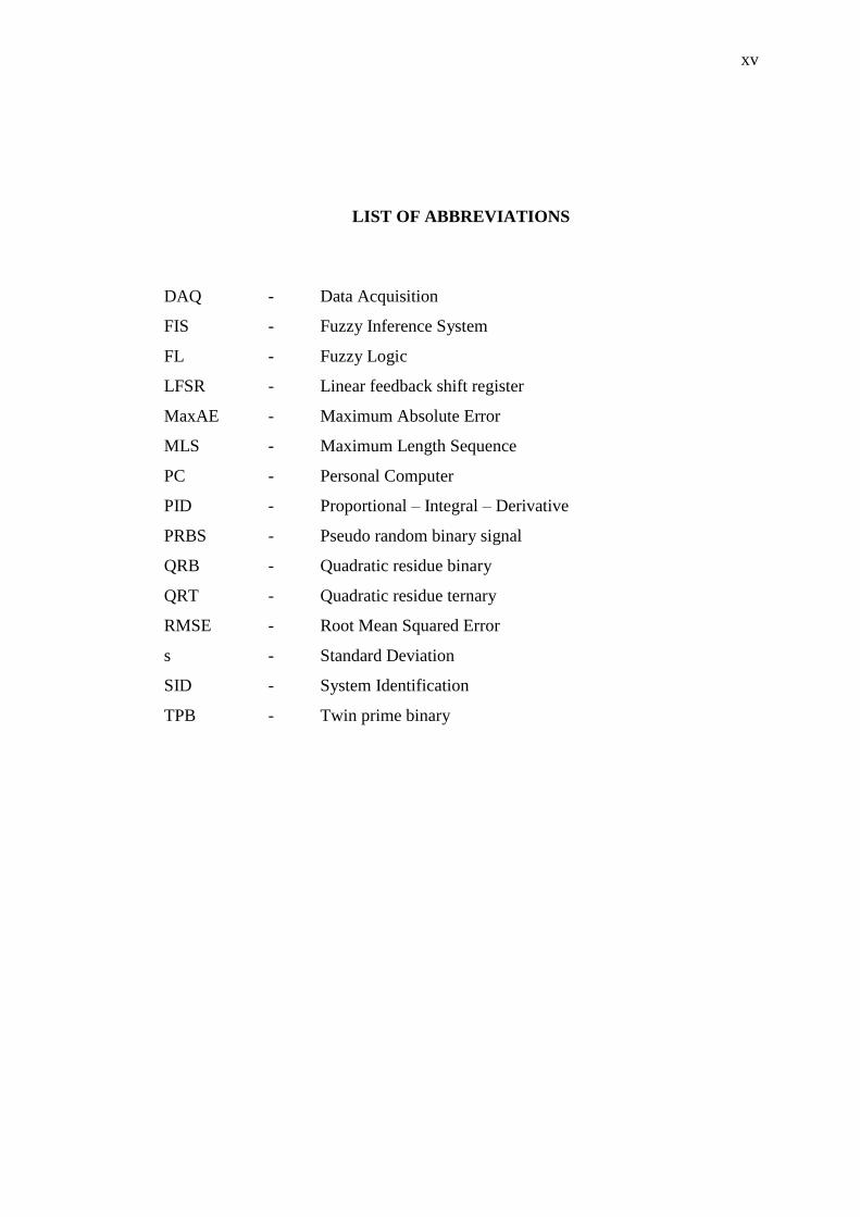
LIST OF ABBREVIATIONS
DAQ - Data Acquisition
FIS - Fuzzy Inference System
FL - Fuzzy Logic
LFSR - Linear feedback shift register
MaxAE - Maximum Absolute Error
MLS - Maximum Length Sequence
PC - Personal Computer
PID - Proportional – Integral – Derivative
PRBS - Pseudo random binary signal
QRB - Quadratic residue binary
QRT - Quadratic residue ternary
RMSE - Root Mean Squared Error
s - Standard Deviation
SID - System Identification
TPB - Twin prime binary
CHAPTER 1
INTRODUCTION
1.1 Project Background
Motorized tables are widely used in the industry today. The usage ranged
from machine tools, electronic assembly and laboratory automation [1]. Examples of
applications such as microscopy, CNC engraver/router, automatic testing/calibration,
pick and place, automatic dispensing, semiconductor inspection, pc board drilling
and plastic fabrication require high accuracy and good repeatability.
The drive system is one of the most critical components in a positioning
system [2] . There are two most used systems, a screw driven system and a belt
driven system. A screw driven system may consists of lead screws or ball screws.
Screw driven systems have higher positioning accuracies but are very expensive to
setup and maintain [2]. A belt driven system in the other hand is a much cheaper
alternative. Besides offering a lower cost it also offers higher speed and much longer
travel [2]. One of the problems with belt driven systems is the difficulties in
controlling their position. These difficulties arise from nonlinearities within the
system, such as belt flexibility, stretch, vibration, backlash, friction, loads change,
delays and other nonlinearities [1], [2]. Since the cost advantage is very attractive,
various controllers were developed by researchers to address these aforementioned
problems.
2
1.2 Problem Statement
It was established that belted system for motorized table system is desirable
due to its lower cost and higher linear speed achievable than ball screw system. The
cost of the belting system could be as low as 30% of the cost of a ball screw system
[3]. But the elasticity of the belt combined with Coulomb friction of the system
caused inaccuracies in table position [4] . Therefore, a controller which can address
the elasticity and Coulomb friction problem to improve positional accuracies is
desired. It was proposed that a Fuzzy Logic Controller coupled with a friction and
elasticity compensator can overcome the aforementioned problems.
1.3 Project Objectives
The objectives of the project are:
i. To design a positional controller using PID controller and FL controller.
ii. To overcome the issues of friction and elasticity by using compensator.
iii. To simulate the system and validate the result via experiment.
1.4 Project Scope
This project focused on a flat belt conveyor system with DC motor which
equipped with an existing driver, in a laboratory scale experiment which was readily
available in the PLC laboratory of the German-Malaysian Institute. A mathematical
model derived from fundamental laws will be used as the basis for its system
identification using MATLAB System Identification Toolbox. The design stage of
the controllers utilized MATLAB Simulink environment. The hardware
implementation of the controllers was by Advantech PCI-1716 data acquisition card
3
with PC running Simulink Real-Time Windows Target executable acted as the
controllers. Then the performance of the FL controller and frictional and elasticity
compensator were compared against the developed PID controller.
1.5 Project Report Outline
Chapter one served as the introduction to the project, stating its objectives
and also scope of work. Chapter two introduced the theory involved in this project
and also literature that has been reviewed. Chapter three elaborates on the
methodology including the equipment used in this project. Chapter four is where the
results including the controllers developed and analysis on the positional accuracies
are discussed. The conclusion and possible future work of the project are presented
in chapter five.
60
REFERENCES
[1] W. Li and X. Cheng, "Adaptive High Precision Control of Positioning Tables -
Theory and Experiments," IEEE Transactions on Control Systems Technology,
vol. 2, no. 3, pp. 265-270, 1994.
[2] M. A. El-Sharkawi and Y. Guo, "Adaptive Fuzzy Control of a Belt-Driven
Precision Positioning Table," in IEEE international Electric Machines and