52
Position Switches according to EN 50041 EN
DEDEDEDEDE
Position Switches accordingto EN 50041
EN
0766
43-0
8-12
/13
Subj
ect t
o te
chni
cal m
odifi
catio
ns w
ithou
t not
ice,
no
liabi
lity
will
be a
ssum
ed fo
r any
det
ail.
© E
UCH
NER
Gm
bH +
Co.
KG
· TA
Posschalter 50041.indd 2 17.12.13 14:54

2
Internationally successful – the EUCHNER company
EUCHNER GmbH + Co. KG is a world-leading company in the area of industrial safety technology. EUCHNER has been developing and producing high-quality switching sys-tems for mechanical and systems engineering for more than 60 years.The medium-sized family-operated company based in Leinfelden, Germany, employs more than 600 people around the world.
In addition to the production locations in Unterböhringen and Shanghai/China, 15 sub-sidiaries and other sales partners in Germany and abroad work for our international success on the market.
Quality and innovation – the EUCHNER products
A look into the past shows EUCHNER to be a company with a great inventive spirit.We take the technological and ecological challenges of the future as an incentive for extraordinary product developments.
EUCHNER safety switches monitor safety doors on machines and installations, help to minimize dangers and risks and thereby reliably protect people and processes. Today, our products range from electromechanical and electronic components to intelligent integrated safety solutions. Safety for people, machines and products is one of our dominant themes.
We defi ne future safety technology with the highest quality standards and reliable technology. Extraordinary solutions ensure the great satisfaction of our customers. The product ranges are subdivided as follows:
Transponder-coded Safety Switches (CES) Transponder-coded Safety Switches with guard locking (CET) Interlocking and guard locking systems (Multifunctional Gate Box MGB) Access management systems (Electronic-Key-System EKS) Electromechanical Safety Switches Magnetically coded Safety Switches (CMS) Enabling Switches Safety Relays Emergency Stop Devices Hand-Held Pendant Stations and Handwheels Safety Switches with AS-Interface Joystick Switches Position Switches
Headquarters in Leinfelden-Echterdingen
madeinGermany
Logistics center in Leinfelden-Echterdingen
Production location in Unterböhringen
U2_U3_EN_2013.indd 1 20.01.14 11:10
Contents
3
General information 4
Advantages and features 5
Application examples 6
The position switch in detail 7
Adjustment options 8
Switching elements 9
Wiring diagrams 10
Plunger types 11
Position switch with lever arm 12
Series NG…/NZ… with cable entry M20 x 1.5
with plug connectors SR6 and SR11
with M12 plug connector SVM5
Position switch with adjustable lever arm 18
Series NG…/NZ… with cable entry M20 x 1.5
with M12 plug connector SVM5
Position switch with pivoted lever arm 22
Series NG… with cable entry M20 x 1.5
with M12 plug connector SVM5
Position switch with plunger actuator 26
Series NG…/NZ… with cable entry M20 x 1.5
with plug connectors SR6 and SR11
with M12 plug connector SVM5
Position switch with spring actuator 38
Series NG… with cable entry M20 x 1.5
with M12 plug connector SVM5
Special versions 42
Spare parts and accessories 45
Position Switches According to EN 50041
076643-08-12/13

4
Position Switches According to EN 50041
Subject to technical modifications; no responsibility is accepted for the accuracy of this information.
General information
EUCHNER position switches are manufactured in accordance with Euro-pean standard EN 50041. Robust construction and the use of high quality corrosion resistant materials, precision finishing and degree of protection IP 67 according to IEC 60529 guarantee trouble-free and reliable operation under the toughest conditions.
Various EUCHNER position switch variants are also equipped as safety switches with switching elements whose NC contacts are positively opened by a rigid plunger, even if the switching element is damaged due to a broken spring or contact weld. Positively driven position switches are used in those cases where a guarantee of machine and/or human safety is absolutely essential, e.g. end travel position switching or an EMERGENCY STOP.
position switches – precise, reliable and versatile
Approvals for series NG… and NZ…
5
Position Switches According to EN 50041
Subject to technical modifications; no responsibility is accepted for the accuracy of this information.
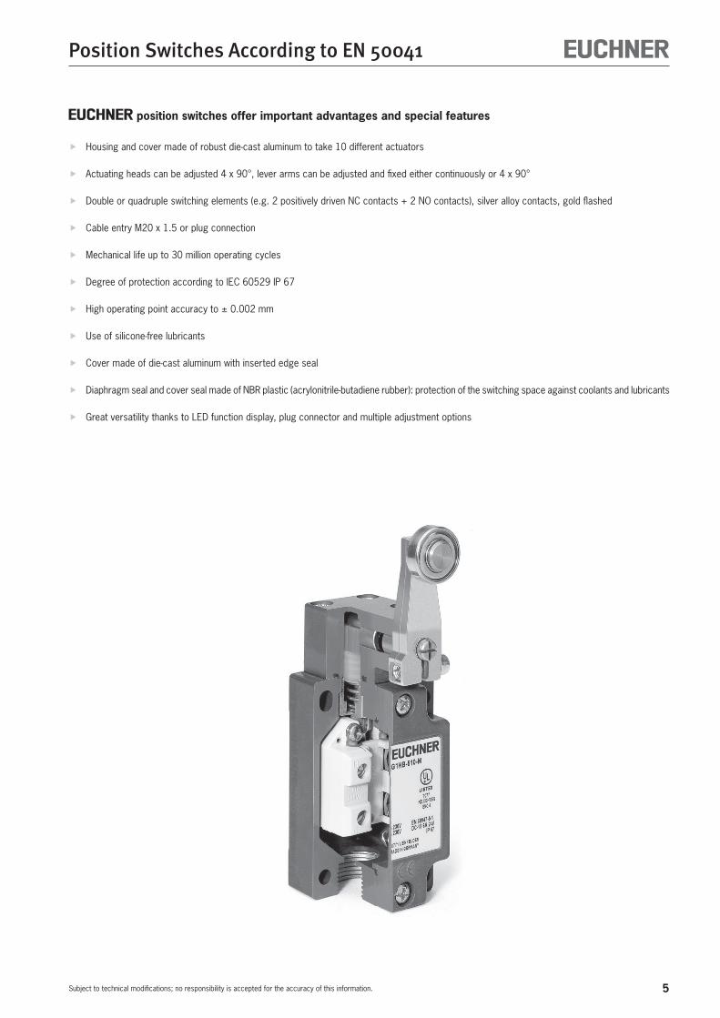
position switches offer important advantages and special features
f Housing and cover made of robust die-cast aluminum to take 10 different actuators
f Actuating heads can be adjusted 4 x 90°, lever arms can be adjusted and fixed either continuously or 4 x 90°
f Double or quadruple switching elements (e.g. 2 positively driven NC contacts + 2 NO contacts), silver alloy contacts, gold flashed
f Cable entry M20 x 1.5 or plug connection
f Mechanical life up to 30 million operating cycles
f Degree of protection according to IEC 60529 IP 67
f High operating point accuracy to ± 0.002 mm
f Use of silicone-free lubricants
f Cover made of die-cast aluminum with inserted edge seal
f Diaphragm seal and cover seal made of NBR plastic (acrylonitrile-butadiene rubber): protection of the switching space against coolants and lubricants
f Great versatility thanks to LED function display, plug connector and multiple adjustment options
6
Position Switches According to EN 50041
Subject to technical modifications; no responsibility is accepted for the accuracy of this information.
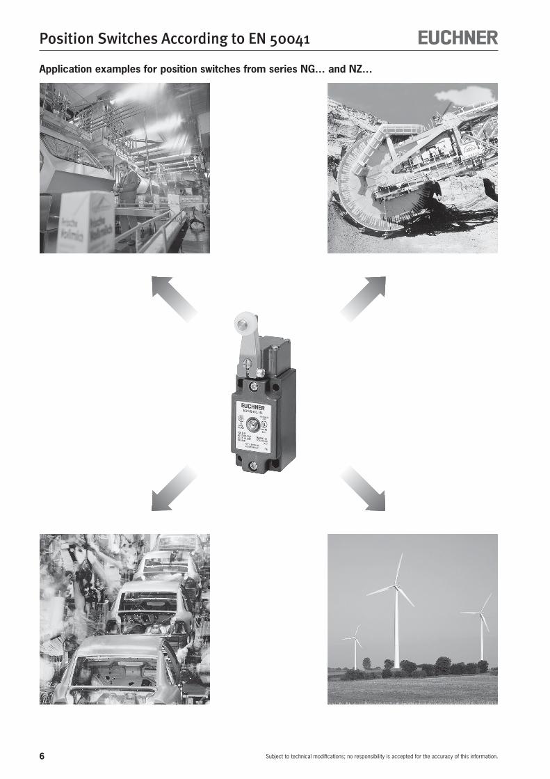
Application examples for position switches from series NG… and NZ…
7
Position Switches According to EN 50041
Subject to technical modifications; no responsibility is accepted for the accuracy of this information.
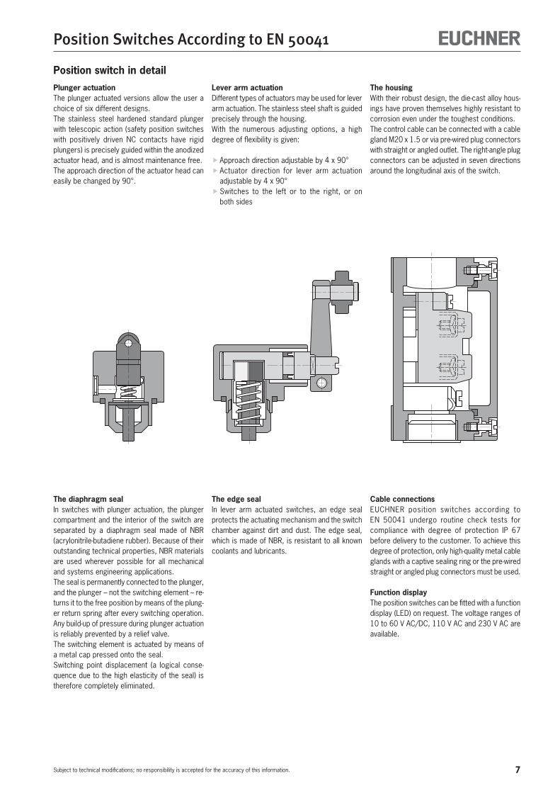
Position switch in detailPlunger actuationThe plunger actuated versions allow the user a choice of six different designs.The stainless steel hardened standard plunger with telescopic action (safety position switches with positively driven NC contacts have rigid plungers) is precisely guided within the anodized actuator head, and is almost maintenance free.The approach direction of the actuator head can easily be changed by 90°.
Lever arm actuationDifferent types of actuators may be used for lever arm actuation. The stainless steel shaft is guided precisely through the housing.With the numerous adjusting options, a high degree of flexibility is given:
f Approach direction adjustable by 4 x 90° f Actuator direction for lever arm actuation adjustable by 4 x 90° fSwitches to the left or to the right, or on both sides
The housingWith their robust design, the die-cast alloy hous-ings have proven themselves highly resistant to corrosion even under the toughest conditions.The control cable can be connected with a cable gland M20 x 1.5 or via pre-wired plug connectors with straight or angled outlet. The right-angle plug connectors can be adjusted in seven directions around the longitudinal axis of the switch.
The diaphragm sealIn switches with plunger actuation, the plunger compartment and the interior of the switch are separated by a diaphragm seal made of NBR (acrylonitrile-butadiene rubber). Because of their outstanding technical properties, NBR materials are used wherever possible for all mechanical and systems engineering applications.The seal is permanently connected to the plunger, and the plunger – not the switching element – re-turns it to the free position by means of the plung-er return spring after every switching operation.Any build-up of pressure during plunger actuation is reliably prevented by a relief valve.The switching element is actuated by means of a metal cap pressed onto the seal.Switching point displacement (a logical conse-quence due to the high elasticity of the seal) is therefore completely eliminated.
The edge sealIn lever arm actuated switches, an edge seal protects the actuating mechanism and the switch chamber against dirt and dust. The edge seal, which is made of NBR, is resistant to all known coolants and lubricants.
Cable connectionsEUCHNER position switches according to EN 50041 undergo routine check tests for compliance with degree of protection IP 67 before delivery to the customer. To achieve this degree of protection, only high-quality metal cable glands with a captive sealing ring or the pre-wired straight or angled plug connectors must be used.
Function displayThe position switches can be fitted with a function display (LED) on request. The voltage ranges of 10 to 60 V AC/DC, 110 V AC and 230 V AC are available.

8
Position Switches According to EN 50041
Subject to technical modifications; no responsibility is accepted for the accuracy of this information.
Adjustment optionsActuator and approach directions
Lever arm HS = steel roller WO = domed plunger RG = plastic roller HB = plastic roller KO = ball plunger RS, RK, RL = steel roller
The large selection of actuator heads guarantees maximum flexibility and is suitable for a variety of applications. For example, the aluminum lever arm is used for high approach speeds and generous actuating mechanism tolerances. The chisel plunger with polish-ground surface is designed for a high operating point accuracy of ± 0.002 mm. The ball plungers can be actuated from a number of different directions.
Lever arm Straight actuator
After removal of the stainless steel fixing screws, the actuator heads can each be adjusted hori-zontally by 90°.
Adjustment option for the actuatorHorizontal adjustment 4 x 90°
The lever arm can be adjusted continuously for position switches without a safety function and by 90° for position switches with a safety function.
Vertical adjustment 4 x 90°
On delivery, the lever arm actuation is set to left and right switching. If necessary, it can be set to right switching or left switching only.
Adjustment option for switching direction
left/right switching right switching left switching (default setting)

9
Position Switches According to EN 50041
Subject to technical modifications; no responsibility is accepted for the accuracy of this information.
Switching elements Switching element 510 2) (without positively driven NC con-tact)Snap-action switching contact with one NC contact and one NO contact.Double gap, electrically isolated switching bridge, silver alloy gold flashed contact, screw terminal with self-lifting clamp washers.Used for NG…
Switching element 511 2)
Snap-action switching contact with one positively driven NC contact and one NO contact.Double gap, electrically isolated contacts, silver alloy gold flashed contact, screw terminal with self-lift-ing clamp washers.Used for NZ…
Switching element 528H 1) 3)
Slow-action switching contact with one positively driven NC contact and one NO contact.Double gap, electrically isolated H contact bridges for currents from 1 mA to 4 A, silver alloy gold flashed contact, screw terminal with self-lift-ing clamp washers.Used for NZ…
Switching element 538H 1) 3)
Slow-action switching contact with two positively driven NC contacts.Double gap, electrically isolated H contact bridges for currents from 1 mA to 4 A, silver alloy gold flashed contact, screw terminal with self-lift-ing clamp washers.Used for NZ…
1) Slow-action switching element The slow-action switching element has a switching contact which opens and closes depending on its actuation speed. 2) Snap-action switching element The snap-action switching element has a switching contact which opens and closes regardless of its actuation speed.3) H contact bridge The design properties of the H contact bridge (H-shaped) ensure that these switching elements reliably switch currents from 1 mA to 4 A.
EUCHNER position switches marked with this symbol meet the IEC 60947-5-1 requirements for positively driven position switches. Safety switching elements marked with this symbol are not available as replacement switching elements.
Switching element 2131 H 3)
Slow-action switching contact with three positively driven NC contacts and one NO contact.Double gap, electrically isolated H contact bridges for currents from 1 mA to 4 A, silver alloy gold flashed contact, screw terminal with self-lift-ing clamp washers.Used for NZ…
Switching element 3131 H 3)
Slow-action switching contact with two positively driven NC contacts and two NO contacts.Double gap, electrically isolated H contact bridges for currents from 1 mA to 4 A, silver alloy gold flashed contact, screw terminal with self-lift-ing clamp washers.Used for NZ…
Switching element 2121 H 3)
Slow-action switching contact with four positively driven NC contacts.Double gap, electrically isolated H contact bridges for currents from 1 mA to 4 A, silver alloy gold flashed contact, screw terminal with self-lift-ing clamp washers.Used for NZ…
4142
33 34
2122
1112
4142
34
2122
13 14
33
4142
31
2122
1112
32

10
Position Switches According to EN 50041
Subject to technical modifications; no responsibility is accepted for the accuracy of this information.
Wiring diagrams
Plug connector SVM5(M12, 5-pin)
Pin assignment for male socket(top view of
switch mounted connector)
Terminal assignment for switching elements
4
31
2
Plug connector SR6
Pin assignment for male socket(top view of
switch mounted connector)
Terminal assignment for switching elements
510 / 511 / 528H 538H
with LED indicator
3
1
4
2
13
21
14
22
5 6
3
1
4
2
13
21
14
22
3
1
4
2
11
21
12
22
5 6
3
1
4
2
11
21
12
22
with LED indicator
for connection cross section 1.5 mm²
A
10
5
50 90 °C
Current rating curve
Plug connector SR11
Pin assignment for male socket(top view of
switch mounted connector)
Terminal assignment for switching elements
7
5
3
1
8
6
4
2
41
33
21
11
42
34
22
12
7
5
3
1
8
6
4
2
41
33
21
13
42
34
22
14
7
5
3
1
8
6
4
2
41
31
21
11
42
32
22
12
2131H 3131H
2121H
for connection cross section 0.5 mm²
A
5
50 90 °C
Current rating curve
510 / 511 / 528H 538H
3
1
4
2
13
21
14
22
5 6
3
1
4
2
13
21
14
22
3
1
4
2
11
21
12
22
5 6
3
1
4
2
11
21
12
22
1 2
4
21
13
22
14
3
with LED indicator
1 2
4
21
11
22
12
3
with LED indicator
11
Position Switches According to EN 50041
Subject to technical modifications; no responsibility is accepted for the accuracy of this information.
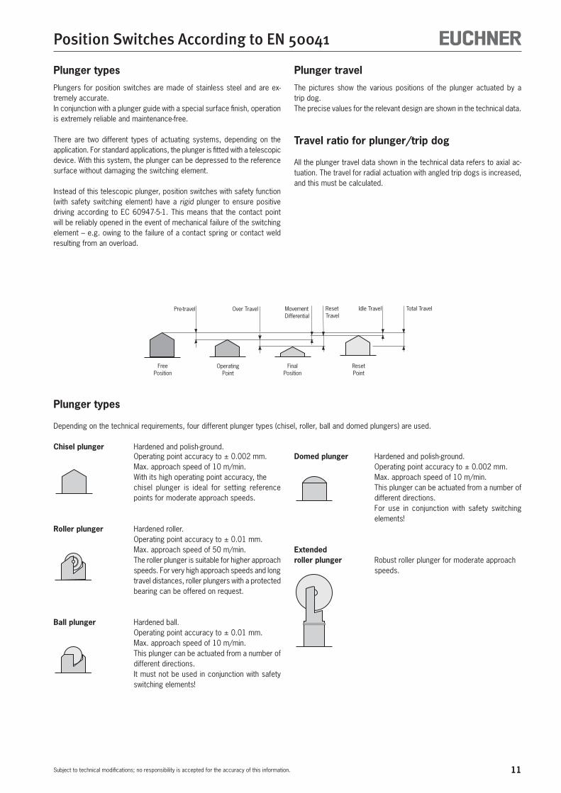
Plunger typesPlungers for position switches are made of stainless steel and are ex-tremely accurate. In conjunction with a plunger guide with a special surface finish, operation is extremely reliable and maintenance-free.
There are two different types of actuating systems, depending on the application. For standard applications, the plunger is fitted with a telescopic device. With this system, the plunger can be depressed to the reference surface without damaging the switching element.
Instead of this telescopic plunger, position switches with safety function (with safety switching element) have a rigid plunger to ensure positive driving according to EC 60947-5-1. This means that the contact point will be reliably opened in the event of mechanical failure of the switching element – e.g. owing to the failure of a contact spring or contact weld resulting from an overload.
FreePosition
OperatingPoint
FinalPosition
ResetPoint
Total TravelIdle TravelResetTravel
MovementDifferential
Over TravelPre-travel
Plunger travel
Plunger types
Depending on the technical requirements, four different plunger types (chisel, roller, ball and domed plungers) are used.
Chisel plunger Hardened and polish-ground. Operating point accuracy to ± 0.002 mm. Max. approach speed of 10 m/min. With its high operating point accuracy, the
chisel plunger is ideal for setting reference points for moderate approach speeds.
Roller plunger Hardened roller. Operating point accuracy to ± 0.01 mm. Max. approach speed of 50 m/min. The roller plunger is suitable for higher approach
speeds. For very high approach speeds and long travel distances, roller plungers with a protected bearing can be offered on request.
Ball plunger Hardened ball. Operating point accuracy to ± 0.01 mm. Max. approach speed of 10 m/min. This plunger can be actuated from a number of
different directions. It must not be used in conjunction with safety
switching elements!
Domed plunger Hardened and polish-ground. Operating point accuracy to ± 0.002 mm. Max. approach speed of 10 m/min. This plunger can be actuated from a number of
different directions. For use in conjunction with safety switching
elements!
Extended roller plunger Robust roller plunger for moderate approach
speeds.
The pictures show the various positions of the plunger actuated by a trip dog.The precise values for the relevant design are shown in the technical data.
Travel ratio for plunger/trip dog
All the plunger travel data shown in the technical data refers to axial ac-tuation. The travel for radial actuation with angled trip dogs is increased, and this must be calculated.

12
Position Switches According to EN 50041
Subject to technical modifications; no responsibility is accepted for the accuracy of this information.
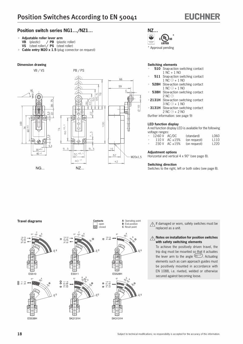
Position switch series NG1…/NZ1…
Dimension drawing Switching elementsf 510 Snap-action switching contact
1 NC + 1 NOf 511 Snap-action switching contact
1 NC + 1 NOf 528H Slow-action switching contact
1 NC + 1 NOf 538H Slow-action switching contact
2 NC f 2131H Slow-action switching contact
3 NC + 1 NOf 3131H Slow-action switching contact
2 NC + 2 NO(further information: see page 9)
LED function displayA red function display LED is available for the following voltage ranges:f 12-60 V AC/DC L060f 110 V AC ±15% L110f 230 V AC ±15% (on request) L220
Adjustment optionsHorizontal and vertical 4 x 90° (see page 8).
Switching directionSwitches to the right, left or both sides (see page 8).
M20x1,5
30° max.
52+
1
ES511 ES528H
ES538H SK2131H SK3131H
ES510
A
B
C A
B
C
A
B
A
A
B
AA
B
AAA
B
f Roller lever arm HB (plastic roller) HS (steel roller)
f Cable entry M20 x 1.5
NG… NZ…
Travel diagrams Contacts A Operating point open B End position
closed C Reset point If damaged or worn, safety switches must be replaced as a unit.
Notes on installation for position switches with safety switching elements
To achieve the positively driven travel, the dimension 52 +1 must be maintained by the trip dog. Actuating elements such as cam approach guides must be positively mounted in accordance with EN 1088, i.e. riveted, welded or otherwise secured against becoming loose.
13
Position Switches According to EN 50041
Subject to technical modifications; no responsibility is accepted for the accuracy of this information.
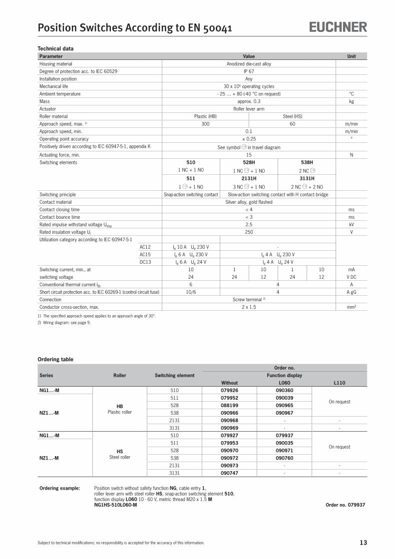
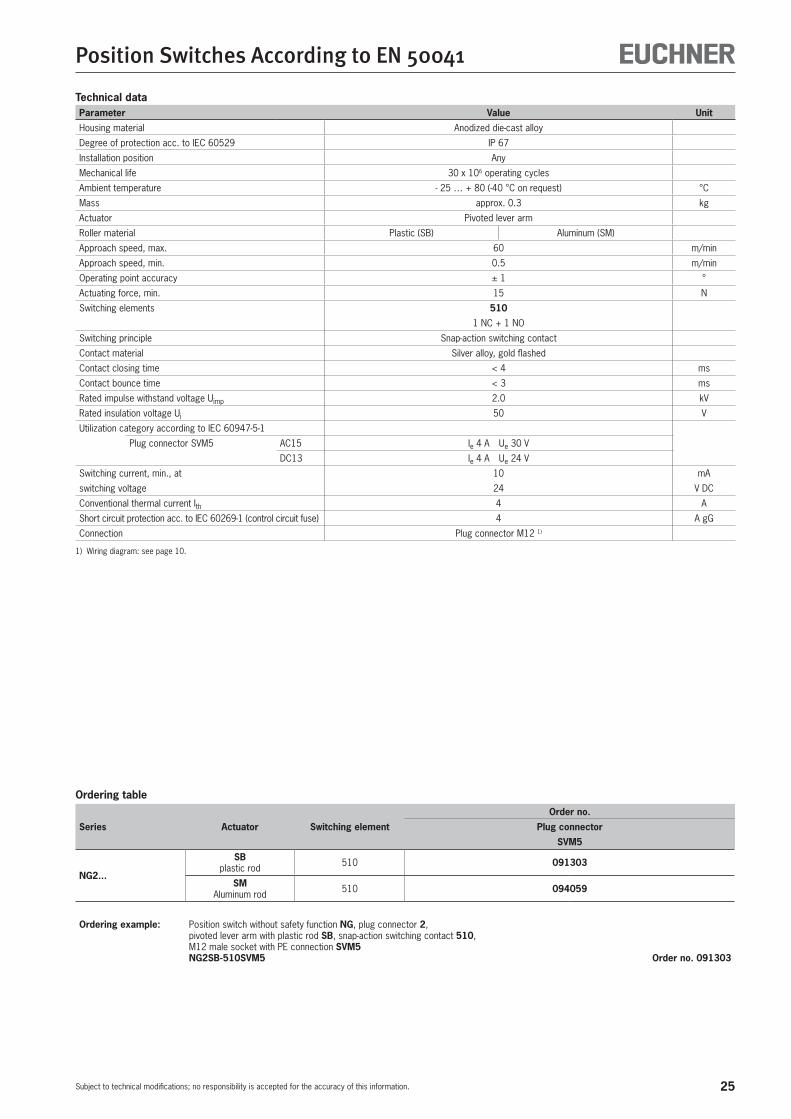
Technical dataParameter Value Unit
Housing material Anodized die-cast alloy
Degree of protection acc. to IEC 60529 IP 67
Installation position Any
Mechanical life 30 x 106 operating cycles
Ambient temperature - 25 … + 80 (-40 °C on request) °C
Mass approx. 0.3 kg
Actuator Roller lever arm
Roller material Plastic (HB) Steel (HS)
Approach speed, max. 1) 300 60 m/min
Approach speed, min. 0.1 m/min
Operating point accuracy ± 0.25 °
Positively driven according to IEC 60947-5-1, appendix K See symbol in travel diagram
Actuating force, min. 15 N
Switching elements 510 528H 538H
1 NC + 1 NO 1 NC + 1 NO 2 NC
511 2131H 3131H
1 + 1 NO 3 NC + 1 NO 2 NC + 2 NO
Switching principle Snap-action switching contact Slow-action switching contact with H contact bridge
Contact material Silver alloy, gold flashed
Contact closing time < 4 ms
Contact bounce time < 3 ms
Rated impulse withstand voltage Uimp 2.5 kV
Rated insulation voltage Ui 250 V
Utilization category according to IEC 60947-5-1
AC12 Ie 10 A Ue 230 V -
AC15 Ie 6 A Ue 230 V Ie 4 A Ue 230 V
DC13 Ie 6 A Ue 24 V Ie 4 A Ue 24 V
Switching current, min., at 10 1 10 1 10 mA
switching voltage 24 24 12 24 12 V DC
Conventional thermal current Ith 6 4 A
Short circuit protection acc. to IEC 60269-1 (control circuit fuse) 10/6 4 A gG
Connection Screw terminal 2)
Conductor cross-section, max. 2 x 1.5 mm²
1) The specified approach speed applies to an approach angle of 30°.
2) Wiring diagram: see page 9.
Ordering table
Series Roller Switching element
Order no.
Function display
Without L060 L110
NG1…-M
HBPlastic roller
510 079926 090360
On request
NZ1…-M
511 079952 090039
528 088199 090965
538 090966 090967
2131 090968 - -
3131 090969 - -
NG1…-M
HSSteel roller
510 079927 079937
On request
NZ1…-M
511 079953 090035
528 090970 090971
538 090972 090760
2131 090973 - -
3131 090747 - -
Ordering example: Position switch without safety function NG, cable entry 1, roller lever arm with steel roller HS, snap-action switching element 510, function display L060 10 - 60 V, metric thread M20 x 1.5 M NG1HS-510L060-M Order no. 079937
14
Position Switches According to EN 50041
Subject to technical modifications; no responsibility is accepted for the accuracy of this information.
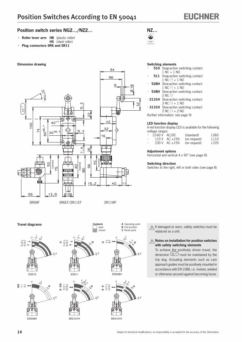
Position switch series NG2…/NZ2…
Switching elementsf 510 Snap-action switching contact
1 NC + 1 NOf 511 Snap-action switching contact
1 NC + 1 NOf 528H Slow-action switching contact
1 NC + 1 NOf 538H Slow-action switching contact
2 NC f 2131H Slow-action switching contact
3 NC + 1 NOf 3131H Slow-action switching contact
2 NC + 2 NO(further information: see page 9)
LED function displayA red function display LED is available for the following voltage ranges:f 12-60 V AC/DC (standard) L060f 110 V AC ±15% (on request) L110f 230 V AC ±15% (on request) L220
Adjustment optionsHorizontal and vertical 4 x 90° (see page 8).
Switching directionSwitches to the right, left or both sides (see page 8).
SR6WF SR6EF/SR11EF SR11WF30° m
ax.
52+
1
ES511 ES528H
ES538H SK2131H SK3131H
ES510
A
B
C A
B
C
A
B
A
A
B
AA
B
AAA
B
Inse
rted
Inse
rted
Inse
rted
f Roller lever arm HB (plastic roller) HS (steel roller)
f Plug connectors SR6 and SR11
NZ…
Dimension drawing
Travel diagrams Contacts A Operating point open B End position
closed C Reset point If damaged or worn, safety switches must be replaced as a unit.
Notes on installation for position switches with safety switching elements
To achieve the positively driven travel, the dimension 52 +1 must be maintained by the trip dog. Actuating elements such as cam approach guides must be positively mounted in accordance with EN 1088, i.e. riveted, welded or otherwise secured against becoming loose.
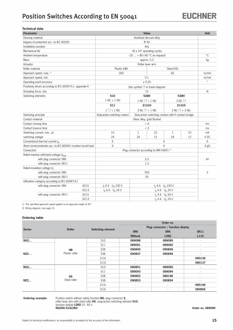
15
Position Switches According to EN 50041
Subject to technical modifications; no responsibility is accepted for the accuracy of this information.
Technical dataParameter Value Unit
Housing material Anodized die-cast alloy
Degree of protection acc. to IEC 60529 IP 65
Installation position Any
Mechanical life 30 x 106 operating cycles
Ambient temperature - 25 … + 80 (-40 °C on request) °C
Mass approx. 0.3 kg
Actuator Roller lever arm
Roller material Plastic (HB) Steel (HS)
Approach speed, max. 1) 300 60 m/min
Approach speed, min. 0.1 m/min
Operating point accuracy ± 0.25 °
Positively driven according to IEC 60947-5-1, appendix K See symbol in travel diagram
Actuating force, min. 15 N
Switching elements 510 528H 538H
1 NC + 1 NO 1 NC + 1 NO 2 NC
511 2131H 3131H
1 + 1 NO 3 NC + 1 NO 2 NC + 2 NO
Switching principle Snap-action switching contact Slow-action switching contact with H contact bridge
Contact material Silver alloy, gold flashed
Contact closing time < 4 ms
Contact bounce time < 3 ms
Switching current, min., at 10 1 10 1 10 mA
switching voltage 24 24 12 24 12 V DC
Conventional thermal current Ith 6 4 A
Short circuit protection acc. to IEC 60269-1 (control circuit fuse) 6 4 A gG
Connection Plug connector according to DIN 43651 2)
Rated impulse withstand voltage Uimp
kVwith plug connector SR6 2.5
with plug connector SR11 1.5
Rated insulation voltage Ui
Vwith plug connector SR6 250
with plug connector SR11 50
Utilization category according to IEC 60947-5-1
with plug connector SR6 AC15 Ie 6 A Ue 230 V Ie 4 A Ue 230 V
DC13 Ie 6 A Ue 24 V Ie 4 A Ue 24 V
with plug connector SR11 AC15 Ie 4 A Ue 50 V
DC13 Ie 4 A Ue 24 V
1) The specified approach speed applies to an approach angle of 30°.
2) Wiring diagram: see page 10.
Ordering table
Series Roller Switching element
Order no.
Plug connector / function display
SR6 SR6 SR11
Without L060 L110
NG2...
HBPlastic roller
510 089088 089089 -
NZ2…
511 089091 089092 -
528 090845 090846 -
538 090847 090848 -
2131 - - 090136
3131 - - 090137
NG2...
HSSteel roller
510 090851 089090 -
NZ2…
511 089093 089094 -
528 090852 088196 -
538 090853 090854 -
2131 - - 090146
3131 - - 090856
Ordering example: Position switch without safety function NG, plug connector 2, roller lever arm with steel roller HS, snap-action switching element 510, function display L060 10 - 60 V NG2HS-510L060 Order no. 089090

16
Position Switches According to EN 50041
Subject to technical modifications; no responsibility is accepted for the accuracy of this information.
Position switch series NG2…/NZ2…
Switching elementsf 510 Snap-action switching contact
1 NC + 1 NOf 511 Snap-action switching contact
1 NC + 1 NOf 528H Slow-action switching contact
1 NC + 1 NOf 538H Slow-action switching contact
2 NC (further information: see page 9)
LED function displayAvailable on request
Adjustment optionsHorizontal and vertical 4 x 90° (see page 8).
Switching directionSwitches to the right, left or both sides (see page 8).
ES511 ES528H
ES538H
ES510
A
B
C A
B
C
A
B
A
A
B
6
42
32
30° max.
64
56
74
100
5,3
7,3
5,3
22
60±
0,1
22
45°
16
40 +1
30 ±0,1
26,5
31
32
ø18
52+
1
G u i d e l u g aligned
Right-angle plug connector:male socket adjustable max. 270°.Default setting: cable outlet to the right.
f Roller lever arm HB (plastic roller) HS (steel roller)
f Plug connector M12/SVM5
NZ…
Dimension drawing
Travel diagrams Contacts A Operating point open B End position
closed C Reset point If damaged or worn, safety switches must be replaced as a unit.
Notes on installation for position switches with safety switching elements
To achieve the positively driven travel, the dimension 52 +1 must be maintained by the trip dog. Actuating elements such as cam approach guides must be positively mounted in accordance with EN 1088, i.e. riveted, welded or otherwise secured against becoming loose.

17
Position Switches According to EN 50041
Subject to technical modifications; no responsibility is accepted for the accuracy of this information.
Ordering table
Series Roller Switching element
Order no.
Plug connector
SVM5
NG2...
HBPlastic roller
510 088631
NZ2…
511 090861
528 090864
538 090862
NG2...
HSSteel roller
510 090866
NZ2…
511 090867
528 090868
538 090869
Ordering example: Position switch without safety function NG, plug connector 2, roller lever arm with steel roller HS, snap-action switching element 510, M12 male socket with PE connection SVM5 NG2HS-510SVM5 Order no. 090866
Technical dataParameter Value Unit
Housing material Anodized die-cast alloy
Degree of protection acc. to IEC 60529 IP 67
Installation position Any
Mechanical life 30 x 106 operating cycles
Ambient temperature - 25 … + 80 (-40 °C on request) °C
Mass approx. 0.3 kg
Actuator Roller lever arm
Roller material Plastic (HB) Steel (HS)
Approach speed, max. 1) 300 60 m/min
Approach speed, min. 0.1 m/min
Operating point accuracy ± 0.25 °
Positively driven according to IEC 60947-5-1, appendix K See symbol in travel diagram
Actuating force, min. 15 N
Switching elements 510 528H 538H
1 NC + 1 NO 1 NC + 1 NO 2 NC
511
1 + 1 NO
Switching principle Snap-action switching contact Slow-action switching contact with H contact bridge
Contact material Silver alloy, gold flashed
Contact closing time < 4 ms
Contact bounce time < 3 ms
Rated impulse withstand voltage Uimp 2.0 kV
Rated insulation voltage Ui 50 V
Utilization category according to IEC 60947-5-1
with plug connector SVM5 AC15 Ie 4 A Ue 30 V Ie 4 A Ue 30 V
DC13 Ie 4 A Ue 24 V Ie 4 A Ue 24 V
Switching current, min., at 10 1 10 1 10 mA
switching voltage 24 24 12 24 12 V DC
Conventional thermal current Ith 4 4 A
Short circuit protection acc. to IEC 60269-1 (control circuit fuse) 4 4 A gG
Connection Plug connector M12 2)
1) The specified approach speed applies to an approach angle of 30°.
2) Wiring diagram: see page 10.
18
Position Switches According to EN 50041
Subject to technical modifications; no responsibility is accepted for the accuracy of this information.
Position switch series NG1…/NZ1…
Switching elementsf 510 Snap-action switching contact
1 NC + 1 NOf 511 Snap-action switching contact
1 NC + 1 NOf 528H Slow-action switching contact
1 NC + 1 NOf 538H Slow-action switching contact
2 NC f 2131H Slow-action switching contact
3 NC + 1 NOf 3131H Slow-action switching contact
2 NC + 2 NO(further information: see page 9)
LED function displayA red function display LED is available for the following voltage ranges:f 12-60 V AC/DC (standard) L060f 110 V AC ±15% (on request) L110f 230 V AC ±15% (on request) L220
Adjustment optionsHorizontal and vertical 4 x 90° (see page 8).
Switching directionSwitches to the right, left or both sides (see page 8).
M20x1,5
74
100
5,3
5,3
22
60±
0,1
40 +1
30 ±0,1
7,3
28 -
75
NG... NZ...
66
59
30° max.
ES511 ES528H
ES538H SK2131H SK3131H
ES510
A
B
C A
B
C
A
B
A
A
B
AA
B
AAA
B
45° +5°
45° +5°45° +5°45° +5°
45° +5°45° +5°
VB / VS PB / PS
f Adjustable roller lever arm VB (plastic) / PB (plastic roller) VS (steel roller) / PS (steel roller)
f Cable entry M20 x 1.5 (plug connector on request)
NZ…
*
* Approval pending
Dimension drawing
Travel diagrams Contacts A Operating point open B End position
closed C Reset point If damaged or worn, safety switches must be replaced as a unit.
Notes on installation for position switches with safety switching elements
To achieve the positively driven travel, the trip dog must be mounted so that it actuates the lever arm to the angle 45°+5° . Actuating elements such as cam approach guides must be positively mounted in accordance with EN 1088, i.e. riveted, welded or otherwise secured against becoming loose.
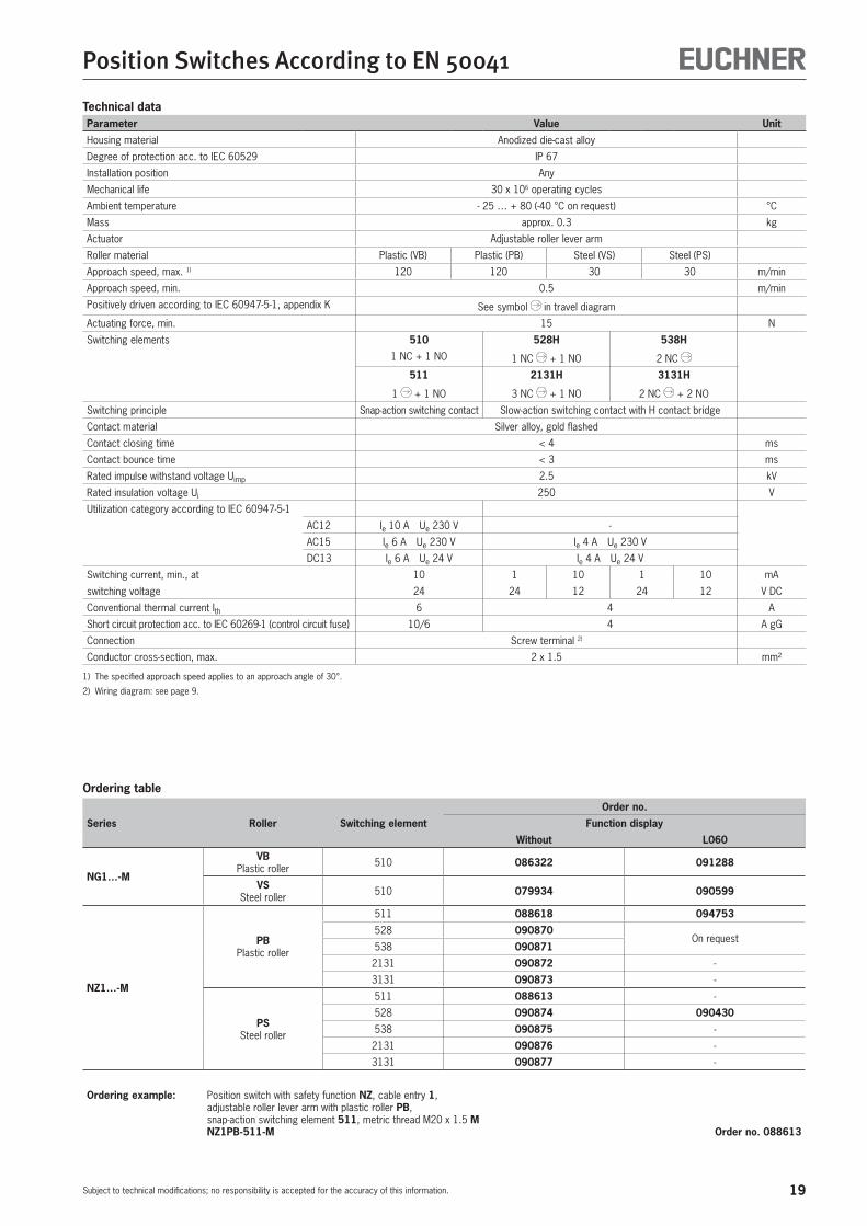
19
Position Switches According to EN 50041
Subject to technical modifications; no responsibility is accepted for the accuracy of this information.
Technical dataParameter Value Unit
Housing material Anodized die-cast alloy
Degree of protection acc. to IEC 60529 IP 67
Installation position Any
Mechanical life 30 x 106 operating cycles
Ambient temperature - 25 … + 80 (-40 °C on request) °C
Mass approx. 0.3 kg
Actuator Adjustable roller lever arm
Roller material Plastic (VB) Plastic (PB) Steel (VS) Steel (PS)
Approach speed, max. 1) 120 120 30 30 m/min
Approach speed, min. 0.5 m/min
Positively driven according to IEC 60947-5-1, appendix K See symbol in travel diagram
Actuating force, min. 15 N
Switching elements 510 528H 538H
1 NC + 1 NO 1 NC + 1 NO 2 NC
511 2131H 3131H
1 + 1 NO 3 NC + 1 NO 2 NC + 2 NO
Switching principle Snap-action switching contact Slow-action switching contact with H contact bridge
Contact material Silver alloy, gold flashed
Contact closing time < 4 ms
Contact bounce time < 3 ms
Rated impulse withstand voltage Uimp 2.5 kV
Rated insulation voltage Ui 250 V
Utilization category according to IEC 60947-5-1
AC12 Ie 10 A Ue 230 V -
AC15 Ie 6 A Ue 230 V Ie 4 A Ue 230 V
DC13 Ie 6 A Ue 24 V Ie 4 A Ue 24 V
Switching current, min., at 10 1 10 1 10 mA
switching voltage 24 24 12 24 12 V DC
Conventional thermal current Ith 6 4 A
Short circuit protection acc. to IEC 60269-1 (control circuit fuse) 10/6 4 A gG
Connection Screw terminal 2)
Conductor cross-section, max. 2 x 1.5 mm²
1) The specified approach speed applies to an approach angle of 30°.
2) Wiring diagram: see page 9.
Ordering table
Series Roller Switching element
Order no.
Function display
Without L060
NG1…-M
VBPlastic roller 510 086322 091288
VSSteel roller 510 079934 090599
NZ1…-M
PBPlastic roller
511 088618 094753
528 090870On request
538 090871
2131 090872 -
3131 090873 -
PSSteel roller
511 088613 -
528 090874 090430
538 090875 -
2131 090876 -
3131 090877 -
Ordering example: Position switch with safety function NZ, cable entry 1, adjustable roller lever arm with plastic roller PB, snap-action switching element 511, metric thread M20 x 1.5 M NZ1PB-511-M Order no. 088613
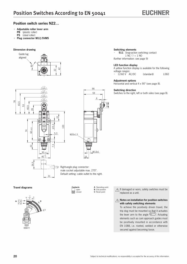
20
Position Switches According to EN 50041
Subject to technical modifications; no responsibility is accepted for the accuracy of this information.
Position switch series NZ2…
Switching elementsf 511 Snap-action switching contact
1 NC + 1 NO(further information: see page 9)
LED function displayA yellow function display is available for the following voltage ranges:f 12-60 V AC/DC (standard) L060
Adjustment optionsHorizontal and vertical 4 x 90° (see page 8).
Switching directionSwitches to the right, left or both sides (see page 8).
ES511 ES528H
ES538H SK2131H SK3131H
ES510
A
B
C A
B
C
A
B
A
A
B
AA
B
AAA
B
45° +5°
45° +5°45° +5°45° +5°
45° +5°45° +5°
28
30 ±0,1
40 0+1
22 7,3
5,3
100
74
5,3
22
40,55365
,578
60±
0,1
18
6
59
66
M12x1
16
M20x1,5
32 42
45°
26,5
31
Guide lug aligned
Right-angle plug connector:male socket adjustable max. 270°.Default setting: cable outlet to the right.
f Adjustable roller lever arm PB (plastic roller) PS (steel roller)
f Plug connector M12/SVM5
Dimension drawing
Travel diagrams Contacts A Operating point open B End position
closed C Reset point If damaged or worn, safety switches must be replaced as a unit.
Notes on installation for position switches with safety switching elements
To achieve the positively driven travel, the trip dog must be mounted so that it actuates the lever arm to the angle 45°+5° . Actuating elements such as cam approach guides must be positively mounted in accordance with EN 1088, i.e. riveted, welded or otherwise secured against becoming loose.

21
Position Switches According to EN 50041
Subject to technical modifications; no responsibility is accepted for the accuracy of this information.
Technical dataParameter Value Unit
Housing material Anodized die-cast alloy
Degree of protection acc. to IEC 60529 IP 67
Installation position Any
Mechanical life 30 x 106 operating cycles
Ambient temperature - 25 … + 80 (-40 °C on request) °C
Mass approx. 0.3 kg
Actuator Adjustable roller lever arm
Roller material Plastic (PB) Steel (PS)
Approach speed, max. 1) 120 30 m/min
Approach speed, min. 0.5 m/min
Positively driven according to IEC 60947-5-1, appendix K See symbol in travel diagram
Actuating force, min. 15 N
Switching elements 511
1 + 1 NO
Switching principle Snap-action switching contact
Contact material Silver alloy, gold flashed
Contact closing time < 4 ms
Contact bounce time < 3 ms
Rated impulse withstand voltage Uimp 2.0 kV
Rated insulation voltage Ui 50 V
Utilization category according to IEC 60947-5-1
with plug connector SVM5 AC15 Ie 4 A Ue 30 V
DC13 Ie 4 A Ue 24 V
Switching current, min., atswitching voltage
10 mA
24 V DC
Conventional thermal current Ith 4 A
Short circuit protection acc. to IEC 60269-1 (control circuit fuse) 4 A gG
Connection Plug connector M12 2)
1) The specified approach speed applies to an approach angle of 30°.
2) Wiring diagram: see page 10.
Ordering table
Series Roller Switching element
Order no.
Function display
Without L060
NZ2…
PBPlastic roller 511 - 098646
PSSteel roller 511 106697 098645
Ordering example: Position switch with safety function NZ, plug connector 2, adjustable roller lever with steel roller PS, snap-action switching element 511, M12 male socket with PE connection SVM5 NZ2PS-511SVM5 Order no. 106697

22
Position Switches According to EN 50041
Subject to technical modifications; no responsibility is accepted for the accuracy of this information.
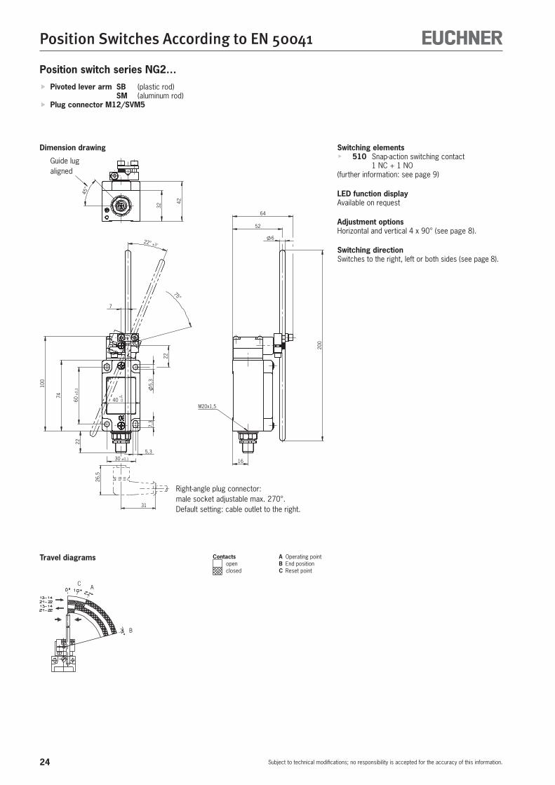
Position switch series NG1…
Switching elementsf 510 Snap-action switching contact
1 NC + 1 NO(further information: see page 9)
LED function displayA red function display LED is available for the following voltage ranges:f 12-60 V AC/DC (standard) L060f 110 V AC ±15% (on request) L110f 230 V AC ±15% (on request) L220
Adjustment optionsHorizontal and vertical 4 x 90° (see page 8).
Switching directionSwitches to the right, left or both sides (see page 8).
7,3
60±
0,1
2007
74
100 5,3
2252
∅ 6
5,3
30 ±0,1
40 +1
16
32
42
M20x1,5
75°
22° ±3°
A
B
C
f Pivoted lever arm SB (plastic rod) SM (aluminum rod)
f Cable entry M20 x 1.5 (plug connector on request)
Dimension drawing
Travel diagrams Contacts A Operating point open B End position
closed C Reset point

23
Position Switches According to EN 50041
Subject to technical modifications; no responsibility is accepted for the accuracy of this information.
Technical dataParameter Value Unit
Housing material Anodized die-cast alloy
Degree of protection acc. to IEC 60529 IP 67
Installation position Any
Mechanical life 30 x 106 operating cycles
Ambient temperature - 25 … + 80 (-40 °C on request) °C
Mass approx. 0.3 kg
Actuator Pivoted lever arm
Roller material Plastic (SB) Aluminum (SM)
Approach speed, max. 60 m/min
Approach speed, min. 0.5 m/min
Operating point accuracy ± 1 °
Actuating force, min. 15 N
Switching elements 510
1 NC + 1 NO
Switching principle Snap-action switching contact
Contact material Silver alloy, gold flashed
Contact closing time < 4 ms
Contact bounce time < 3 ms
Rated impulse withstand voltage Uimp 2.5 kV
Rated insulation voltage Ui 250 V
Utilization category according to IEC 60947-5-1
AC12 Ie 10 A Ue 230 V
AC15 Ie 6 A Ue 230 V
DC13 Ie 6 A Ue 24 V
Switching current, min., at 10 mA
switching voltage 24 V DC
Conventional thermal current Ith 6 A
Short circuit protection acc. to IEC 60269-1 (control circuit fuse) 10/6 A gG
Connection Screw terminal 1)
Conductor cross-section, max. 2 x 1.5 mm²
1) Wiring diagram: see page 9.
Ordering table
Series Actuator Switching element
Order no.
Function display
Without L060
NG1…-M
SBplastic rod 510 088609 090577
SMAluminum rod 510 079932 090575
Ordering example: Position switch without safety function NG, cable entry 1, pivoted lever arm with plastic rod SB, snap-action switching element 510, function display L060 10 - 60 V, metric thread M20 x 1.5 M NG1SB-510L060-M Order no. 090577
24
Position Switches According to EN 50041
Subject to technical modifications; no responsibility is accepted for the accuracy of this information.
Position switch series NG2…
Switching elementsf 510 Snap-action switching contact
1 NC + 1 NO(further information: see page 9)
LED function displayAvailable on request
Adjustment optionsHorizontal and vertical 4 x 90° (see page 8).
Switching directionSwitches to the right, left or both sides (see page 8).
26,5
31
5,3
22
100
74
22
40 0+1
5,3
7,3
30 ±0,1
7
22° ±3°
75°
60±
0,1
52
200
16
64
6
M20x1,5
32
42
45°
Guide lug aligned
Right-angle plug connector:male socket adjustable max. 270°.Default setting: cable outlet to the right.
f Pivoted lever arm SB (plastic rod) SM (aluminum rod)
f Plug connector M12/SVM5
Dimension drawing
Travel diagrams Contacts A Operating point open B End position
closed C Reset point
A
B
C
25
Position Switches According to EN 50041
Subject to technical modifications; no responsibility is accepted for the accuracy of this information.
Technical dataParameter Value Unit
Housing material Anodized die-cast alloy
Degree of protection acc. to IEC 60529 IP 67
Installation position Any
Mechanical life 30 x 106 operating cycles
Ambient temperature - 25 … + 80 (-40 °C on request) °C
Mass approx. 0.3 kg
Actuator Pivoted lever arm
Roller material Plastic (SB) Aluminum (SM)
Approach speed, max. 60 m/min
Approach speed, min. 0.5 m/min
Operating point accuracy ± 1 °
Actuating force, min. 15 N
Switching elements 510
1 NC + 1 NO
Switching principle Snap-action switching contact
Contact material Silver alloy, gold flashed
Contact closing time < 4 ms
Contact bounce time < 3 ms
Rated impulse withstand voltage Uimp 2.0 kV
Rated insulation voltage Ui 50 V
Utilization category according to IEC 60947-5-1
Plug connector SVM5 AC15 Ie 4 A Ue 30 V
DC13 Ie 4 A Ue 24 V
Switching current, min., at 10 mA
switching voltage 24 V DC
Conventional thermal current Ith 4 A
Short circuit protection acc. to IEC 60269-1 (control circuit fuse) 4 A gG
Connection Plug connector M12 1)
1) Wiring diagram: see page 10.
Ordering table
Series Actuator Switching element
Order no.
Plug connector
SVM5
NG2...
SBplastic rod 510 091303
SMAluminum rod 510 094059
Ordering example: Position switch without safety function NG, plug connector 2, pivoted lever arm with plastic rod SB, snap-action switching contact 510, M12 male socket with PE connection SVM5 NG2SB-510SVM5 Order no. 091303

26
Position Switches According to EN 50041
Subject to technical modifications; no responsibility is accepted for the accuracy of this information.
Position switch series NG1…/NZ1…
Switching elementsf 510 Snap-action switching contact
1 NC + 1 NOf 511 Snap-action switching contact
1 NC + 1 NOf 528H Slow-action switching contact
1 NC + 1 NOf 538H Slow-action switching contact
2 NC f 2131H Slow-action switching contact
3 NC + 1 NOf 3131H Slow-action switching contact
2 NC + 2 NO(further information: see page 9)
LED function displayA red function display is available for the following voltage ranges:f 12-60 V AC/DC (standard) L060f 110 V AC ±15% (on request) L110f 230 V AC ±15% (on request) L220
Adjustment optionsHorizontal 4 x 90° (see page 8).
To achieve the positively driven travel, the dimension 31 +1 must be maintained by the trip dog. Actuating elements such as cam approach guides must be positively mounted in accordance with EN 1088, i.e. riveted, welded or otherwise secured against becoming loose.
74
5,3
60±
0,1
40 +1
30 ±0,1
16
32
42
M20x1,5
7,3
5,3
97
R4
31+
1
37±
1
∅ 10
16
30° max.
31+
1
Posi
tivel
y dr
iven
Free
pos
ition
01234
6
13-1
421
-22
13-1
421
-22
ES511
mm
13-1
421
-22
11-1
221
-22
ES528H ES538H
01234
6mm mm
6
43210
SK2131H
41-4
233
-34
21-2
211
-12
6
43210
41-4
233
-34
21-2
213
-14
SK3131H
mm
01234
6mm
2,5
01234
6
13-1
421
-22
13-1
421
-22
ES510
mm
5
01234
6
13-1
421
-22
13-1
421
-22
ES511
mm
13-1
421
-22
11-1
221
-22
ES528H ES538H
01234
6mm mm
6
43210
SK2131H
41-4
233
-34
21-2
211
-12
6
43210
41-4
233
-34
21-2
213
-14
SK3131H
mm
01234
6mm
2,5
01234
6
13-1
421
-22
13-1
421
-22
ES510
mm
5
WODomed plungertype B
(EN 50041)
DOChisel
plunger
KOBall plunger
RKRoller plunger
small
f Plunger actuator WO (domed plunger) / KO (ball plunger) DO (chisel plunger) / RK (roller plunger with small steel roller)
f Cable entry M20 x 1.5
NG… NZ…
Dimension drawing
Travel diagrams
Contacts open
closed

27
Position Switches According to EN 50041
Subject to technical modifications; no responsibility is accepted for the accuracy of this information.
Technical dataParameter Value Unit
Housing material Anodized die-cast alloy
Degree of protection acc. to IEC 60529 IP 67
Installation position Any
Mechanical life 30 x 106 operating cycles
Ambient temperature - 25 … + 80 (-40 °C on request) °C
Mass approx. 0.3 kg
Actuator Domed plunger (WO)
Chisel plunger (DO)
Ball plunger (KO)
Roller plunger, small (RK)
Approach speed, max. 1) 10 50 m/min
Approach speed, min. 0.1 m/min
Operating point accuracy 2) ± 0.002 0.01 mm
Positively driven according to IEC 60947-5-1, appendix K See symbol in travel diagram
Actuating force, min. 15 N
Switching elements 510 528H 538H
1 NC + 1 NO 1 NC + 1 NO 2 NC
511 2131H 3131H
1 + 1 NO 3 NC + 1 NO 2 NC + 2 NO
Switching principle Snap-action switching contact Slow-action switching contact with H contact bridge
Contact material Silver alloy, gold flashed
Contact closing time < 4 ms
Contact bounce time < 3 ms
Rated impulse withstand voltage Uimp 2.5 kV
Rated insulation voltage Ui 250 V
Utilization category according to IEC 60947-5-1
AC12 Ie 10 A Ue 230 V -
AC15 Ie 6 A Ue 230 V Ie 4 A Ue 230 V
DC13 Ie 6 A Ue 24 V Ie 4 A Ue 24 V
Switching current, min., at 10 1 10 1 10 mA
switching voltage 24 24 12 24 12 V DC
Conventional thermal current Ith 6 4 A
Short circuit protection acc. to IEC 60269-1 (control circuit fuse) 10/6 4 A gG
Connection Screw terminal 3)
Conductor cross-section, max. 2 x 1.5 mm²
1) The approach speed specified applies in conjunction with EUCHNER trip dogs according to DIN 69639.
2) The reproducible operating point accuracy refers to the plunger's axial travel, after a run-in of approx. 2,000 operating cycles.
3) Wiring diagram: see page 9.
Ordering table
Series Actuator Switching elementOrder no.
Function displayWithout L060
NG1…-M
WODomed plunger
510 079945 On request
NZ1…-M
511 088611 089057528 089624 089078538 090878 089046
2131 089629 -3131 089626 -
NG1…-M
DOChisel plunger
510 088616
On requestNZ1…-M
511 088620528 090901538 0909022131 0909033131 090904
NG1…-M
RKRoller plunger, small
510 088619 On request
NZ1…-M
511 088608 090354528 090905 090358538 090906 On request
2131 090907 -3131 090908 -
NG1…-M KOBall plunger 510 088604 On request
Ordering example: Position switch with safety function NZ, cable entry 1, domed plunger WO, snap-action switching element 511, function display L060 10 - 60 V, metric thread M20 x 1.5 M NZ1WO-511L060-M Order no. 089057

28
Position Switches According to EN 50041
Subject to technical modifications; no responsibility is accepted for the accuracy of this information.
01234
6
13-1
421
-22
13-1
421
-22
ES511
mm
13-1
421
-22
11-1
221
-22
ES528H ES538H
01234
6mm mm
6
43210
SK2131H
41-4
233
-34
21-2
211
-12
6
43210
41-4
233
-34
21-2
213
-14
SK3131H
mm
01234
6mm
2,5
01234
6
13-1
421
-22
13-1
421
-22
ES510
mm
5
01234
6
13-1
421
-22
13-1
421
-22
ES511
mm
13-1
421
-22
11-1
221
-22
ES528H ES538H
01234
6mm mm
6
43210
SK2131H
41-4
233
-34
21-2
211
-12
6
43210
41-4
233
-34
21-2
213
-14
SK3131H
mm
01234
6mm
2,5
01234
6
13-1
421
-22
13-1
421
-22
ES510
mm
5
Position switch series NG2…/NZ2…
Switching elementsf 510 Snap-action switching contact
1 NC + 1 NOf 511 Snap-action switching contact
1 NC + 1 NOf 528H Slow-action switching contact
1 NC + 1 NOf 538H Slow-action switching contact
2 NC f 2131H Slow-action switching contact
3 NC + 1 NOf 3131H Slow-action switching contact
2 NC + 2 NO(further information: see page 9)
LED function displayA red function display LED is available for the following voltage ranges:f 12-60 V AC/DC (standard) L060f 110 V AC ±15% (on request) L110f 230 V AC ±15% (on request) L220
Adjustment optionsHorizontal 4 x 90° (see page 8).
To achieve the positively driven travel, the dimension 31 +1 must be maintained by the trip dog. Actuating elements such as cam approach guides must be positively mounted in accordance with EN 1088, i.e. riveted, welded or otherwise secured against becoming loose.
30° max.
165,3
26
74
40 +1
30 ±0,1
5,3
7,3
60±
0,1
M20x1,5
31+
1
37±
1
16
∅ 10∅ 8x4
97
SR11WFSR6WF
55 13,5
50
75
40
56
40 1115,2
SR6EF/SR11EF
∅ 28
60
80
31+
1
Inse
rted
Inse
rted Inse
rted
Posi
tivel
y dr
iven
Free
pos
ition
WODomed plungertype B
(EN 50041)
DOChisel
plunger
KOBall plunger
RKRoller plunger
small
f Plunger actuator WO (domed plunger) / KO (ball plunger) DO (chisel plunger) / RK (roller plunger with small steel roller)
f Plug connectors SR6 and SR11
NZ…
Dimension drawing
Travel diagrams
Contacts open
closed
29
Position Switches According to EN 50041
Subject to technical modifications; no responsibility is accepted for the accuracy of this information.
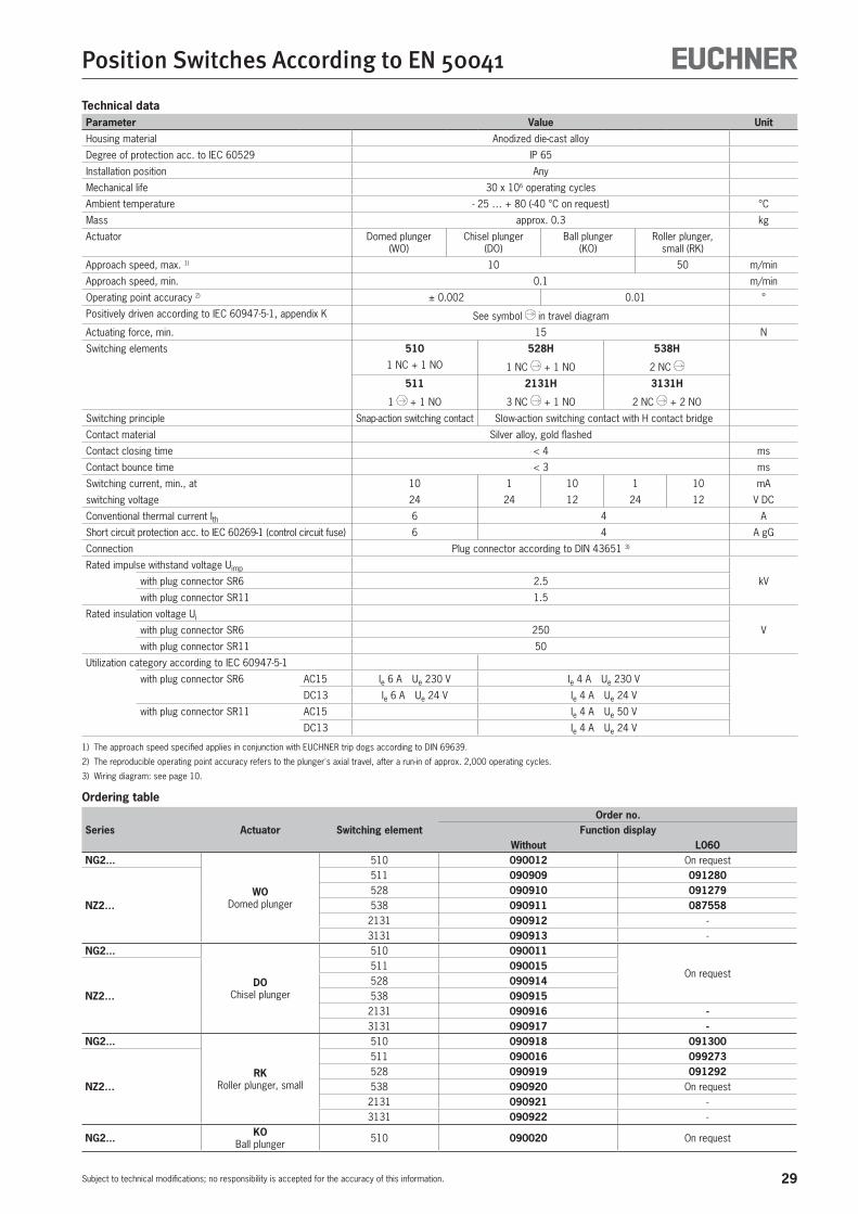
Technical dataParameter Value Unit
Housing material Anodized die-cast alloy
Degree of protection acc. to IEC 60529 IP 65
Installation position Any
Mechanical life 30 x 106 operating cycles
Ambient temperature - 25 … + 80 (-40 °C on request) °C
Mass approx. 0.3 kg
Actuator Domed plunger (WO)
Chisel plunger (DO)
Ball plunger (KO)
Roller plunger, small (RK)
Approach speed, max. 1) 10 50 m/min
Approach speed, min. 0.1 m/min
Operating point accuracy 2) ± 0.002 0.01 °
Positively driven according to IEC 60947-5-1, appendix K See symbol in travel diagram
Actuating force, min. 15 N
Switching elements 510 528H 538H
1 NC + 1 NO 1 NC + 1 NO 2 NC
511 2131H 3131H
1 + 1 NO 3 NC + 1 NO 2 NC + 2 NO
Switching principle Snap-action switching contact Slow-action switching contact with H contact bridge
Contact material Silver alloy, gold flashed
Contact closing time < 4 ms
Contact bounce time < 3 ms
Switching current, min., at 10 1 10 1 10 mA
switching voltage 24 24 12 24 12 V DC
Conventional thermal current Ith 6 4 A
Short circuit protection acc. to IEC 60269-1 (control circuit fuse) 6 4 A gG
Connection Plug connector according to DIN 43651 3)
Rated impulse withstand voltage Uimp
kVwith plug connector SR6 2.5
with plug connector SR11 1.5
Rated insulation voltage Ui
Vwith plug connector SR6 250
with plug connector SR11 50
Utilization category according to IEC 60947-5-1
with plug connector SR6 AC15 Ie 6 A Ue 230 V Ie 4 A Ue 230 V
DC13 Ie 6 A Ue 24 V Ie 4 A Ue 24 V
with plug connector SR11 AC15 Ie 4 A Ue 50 V
DC13 Ie 4 A Ue 24 V
1) The approach speed specified applies in conjunction with EUCHNER trip dogs according to DIN 69639.
2) The reproducible operating point accuracy refers to the plunger's axial travel, after a run-in of approx. 2,000 operating cycles.
3) Wiring diagram: see page 10.
Ordering table
Series Actuator Switching elementOrder no.
Function displayWithout L060
NG2...
WODomed plunger
510 090012 On request
NZ2…
511 090909 091280528 090910 091279538 090911 087558
2131 090912 -3131 090913 -
NG2...
DOChisel plunger
510 090011
On request
NZ2…
511 090015528 090914538 0909152131 090916 -3131 090917 -
NG2...
RKRoller plunger, small
510 090918 091300
NZ2…
511 090016 099273528 090919 091292538 090920 On request
2131 090921 -3131 090922 -
NG2... KOBall plunger 510 090020 On request

30
Position Switches According to EN 50041
Subject to technical modifications; no responsibility is accepted for the accuracy of this information.
01234
6
13-1
421
-22
13-1
421
-22
ES511
mm
13-1
421
-22
11-1
221
-22
ES528H ES538H
01234
6mm mm
6
43210
SK2131H
41-4
233
-34
21-2
211
-12
6
43210
41-4
233
-34
21-2
213
-14
SK3131H
mm
01234
6mm
2,5
01234
6
13-1
421
-22
13-1
421
-22
ES510
mm
5
01234
6
13-1
421
-22
13-1
421
-22
ES511
mm
13-1
421
-22
11-1
221
-22
ES528H ES538H
01234
6mm mm
6
43210
SK2131H
41-4
233
-34
21-2
211
-12
6
43210
41-4
233
-34
21-2
213
-14
SK3131H
mm
01234
6mm
2,5
01234
6
13-1
421
-22
13-1
421
-22
ES510
mm
5
Position switch series NG2…/NZ2…
Switching elementsf 510 Snap-action switching contact
1 NC + 1 NOf 511 Snap-action switching contact
1 NC + 1 NOf 528H Slow-action switching contact
1 NC + 1 NOf 538H Slow-action switching contact
2 NC (further information: see page 9)
LED function displayA red function display LED is available for the following voltage ranges:f 12-60 V AC/DC (standard) L060f 110 V AC ±15% (on request) L110f 230 V AC ±15% (on request) L220
Adjustment optionsHorizontal 4 x 90° (see page 8).
To achieve the positively driven travel, the dimension 31 +1 must be maintained by the trip dog. Actuating elements such as cam approach guides must be positively mounted in accordance with EN 1088, i.e. riveted, welded or otherwise secured against becoming loose.
16
42
32
74
40 +1
30 ±0,1
5,3
7,3
60±
0,1
22
45°
26,5
31
31+
1
37±
1
∅ 10
16
97
5,3 M20x1,5
∅ 8x4
30° max.
31+
1
Guide lug aligned
Right-angle plug connector:male socket adjustable max. 270°.Default setting: cable outlet to the right.
Posi
tivel
y dr
iven
Free
pos
ition
WODomed plungertype B
(EN 50041)
DOChisel
plunger
KOBall plunger
RKRoller plunger
small
f Plunger actuator WO (domed plunger) / KO (ball plunger) DO (chisel plunger) / RK (roller plunger with small steel roller)
f Plug connector M12/SVM5
NZ…
Dimension drawing
Travel diagrams
Contacts open
closed
31
Position Switches According to EN 50041
Subject to technical modifications; no responsibility is accepted for the accuracy of this information.
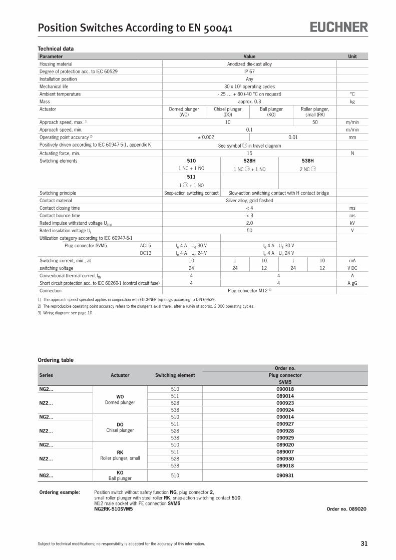
Technical dataParameter Value Unit
Housing material Anodized die-cast alloy
Degree of protection acc. to IEC 60529 IP 67
Installation position Any
Mechanical life 30 x 106 operating cycles
Ambient temperature - 25 … + 80 (-40 °C on request) °C
Mass approx. 0.3 kg
Actuator Domed plunger (WO)
Chisel plunger (DO)
Ball plunger (KO)
Roller plunger, small (RK)
Approach speed, max. 1) 10 50 m/min
Approach speed, min. 0.1 m/min
Operating point accuracy 2) ± 0.002 0.01 mm
Positively driven according to IEC 60947-5-1, appendix K See symbol in travel diagram
Actuating force, min. 15 N
Switching elements 510 528H 538H
1 NC + 1 NO 1 NC + 1 NO 2 NC
511
1 + 1 NO
Switching principle Snap-action switching contact Slow-action switching contact with H contact bridge
Contact material Silver alloy, gold flashed
Contact closing time < 4 ms
Contact bounce time < 3 ms
Rated impulse withstand voltage Uimp 2.0 kV
Rated insulation voltage Ui 50 V
Utilization category according to IEC 60947-5-1
Plug connector SVM5 AC15 Ie 4 A Ue 30 V Ie 4 A Ue 30 V
DC13 Ie 4 A Ue 24 V Ie 4 A Ue 24 V
Switching current, min., at 10 1 10 1 10 mA
switching voltage 24 24 12 24 12 V DC
Conventional thermal current Ith 4 4 A
Short circuit protection acc. to IEC 60269-1 (control circuit fuse) 4 4 A gG
Connection Plug connector M12 3)
1) The approach speed specified applies in conjunction with EUCHNER trip dogs according to DIN 69639.
2) The reproducible operating point accuracy refers to the plunger's axial travel, after a run-in of approx. 2,000 operating cycles.
3) Wiring diagram: see page 10.
Ordering table
Series Actuator Switching elementOrder no.
Plug connectorSVM5
NG2...
WODomed plunger
510 090018
NZ2…511 089014528 090923538 090924
NG2...
DOChisel plunger
510 090014
NZ2…511 090927528 090928538 090929
NG2...
RKRoller plunger, small
510 089020
NZ2…511 089007528 090930538 089018
NG2... KOBall plunger 510 090931
Ordering example: Position switch without safety function NG, plug connector 2, small roller plunger with steel roller RK, snap-action switching contact 510, M12 male socket with PE connection SVM5 NG2RK-510SVM5 Order no. 089020

32
Position Switches According to EN 50041
Subject to technical modifications; no responsibility is accepted for the accuracy of this information.
Position switch series NG1…/NZ1…
Switching elementsf 510 Snap-action switching contact
1 NC + 1 NOf 511 Snap-action switching contact
1 NC + 1 NOf 528H Slow-action switching contact
1 NC + 1 NOf 538H Slow-action switching contact
2 NC f 2131H Slow-action switching contact
3 NC + 1 NOf 3131H Slow-action switching contact
2 NC + 2 NO(further information: see page 9)
LED function displayA red function display LED is available for the following voltage ranges:f 12-60 V AC/DC (standard) L060f 110 V AC ±15% (on request) L110f 230 V AC ±15% (on request) L220
Adjustment optionsHorizontal 4 x 90° (see page 8).
If damaged or worn, safety switches must be replaced as a unit.
Notes on installation for position switches with safety switching elements
To achieve the positively driven travel, the dimension 44 +1 must be maintained by the trip dog. Actuating elements such as cam approach guides must be positively mounted in accordance with EN 1088, i.e. riveted, welded or otherwise secured against becoming loose.
M20x1,5
30° max.
44+
1
Free
pos
ition
Posi
tivel
y dr
iven
RGPlastic roller
RSSteel roller
RLExtended
rollerplunger
01234
6
13-1
421
-22
13-1
421
-22
ES511
mm
13-1
421
-22
11-1
221
-22
ES528H ES538H
01234
6mm mm
6
43210
SK2131H
41-4
233
-34
21-2
211
-12
6
43210
41-4
233
-34
21-2
213
-14
SK3131H
mm
01234
6mm
2,5
01234
6
13-1
421
-22
13-1
421
-22
ES510
mm
5
f Plunger actuator RG (roller plunger, plastic roller) RS (roller plunger, steel roller) RL (extended roller plunger)
f Cable entry M20 x 1.5
NG… NZ…
Dimension drawing
Travel diagrams
Contacts open
closed
33
Position Switches According to EN 50041
Subject to technical modifications; no responsibility is accepted for the accuracy of this information.
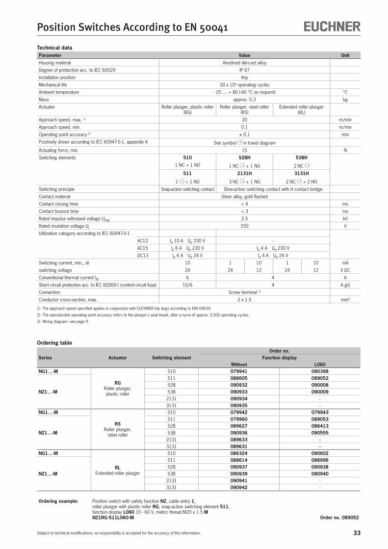
Technical dataParameter Value Unit
Housing material Anodized die-cast alloy
Degree of protection acc. to IEC 60529 IP 67
Installation position Any
Mechanical life 30 x 106 operating cycles
Ambient temperature - 25 … + 80 (-40 °C on request) °C
Mass approx. 0.3 kg
Actuator Roller plunger, plastic roller (RG)
Roller plunger, steel roller (RS)
Extended roller plunger (RL)
Approach speed, max. 1) 20 m/min
Approach speed, min. 0.1 m/min
Operating point accuracy 2) ± 0.1 mm
Positively driven according to IEC 60947-5-1, appendix K See symbol in travel diagram
Actuating force, min. 15 N
Switching elements 510 528H 538H
1 NC + 1 NO 1 NC + 1 NO 2 NC
511 2131H 3131H
1 + 1 NO 3 NC + 1 NO 2 NC + 2 NO
Switching principle Snap-action switching contact Slow-action switching contact with H contact bridge
Contact material Silver alloy, gold flashed
Contact closing time < 4 ms
Contact bounce time < 3 ms
Rated impulse withstand voltage Uimp 2.5 kV
Rated insulation voltage Ui 250 V
Utilization category according to IEC 60947-5-1
AC12 Ie 10 A Ue 230 V -
AC15 Ie 6 A Ue 230 V Ie 4 A Ue 230 V
DC13 Ie 6 A Ue 24 V Ie 4 A Ue 24 V
Switching current, min., at 10 1 10 1 10 mA
switching voltage 24 24 12 24 12 V DC
Conventional thermal current Ith 6 4 A
Short circuit protection acc. to IEC 60269-1 (control circuit fuse) 10/6 4 A gG
Connection Screw terminal 3)
Conductor cross-section, max. 2 x 1.5 mm²
1) The approach speed specified applies in conjunction with EUCHNER trip dogs according to DIN 69639.
2) The reproducible operating point accuracy refers to the plunger's axial travel, after a run-in of approx. 2,000 operating cycles.
3) Wiring diagram: see page 9.
Ordering table
Series Actuator Switching elementOrder no.
Function displayWithout L060
NG1…-M
RGRoller plunger, plastic roller
510 079941 090398
NZ1…-M
511 088605 089052528 090932 090008538 090933 090009
2131 090934 -3131 090935 -
NG1…-M
RSRoller plunger,
steel roller
510 079942 079943
NZ1…-M
511 079960 089053528 089627 086413538 090936 090555
2131 089633 -3131 089631 -
NG1…-M
RLExtended roller plunger
510 086324 090602
NZ1…-M
511 088614 088996528 090937 090938538 090939 090940
2131 090941 -3131 090942 -
Ordering example: Position switch with safety function NZ, cable entry 1, roller plunger with plastic roller RG, snap-action switching element 511, function display L060 10 - 60 V, metric thread M20 x 1.5 M NZ1RG-511L060-M Order no. 089052
34
Position Switches According to EN 50041
Subject to technical modifications; no responsibility is accepted for the accuracy of this information.
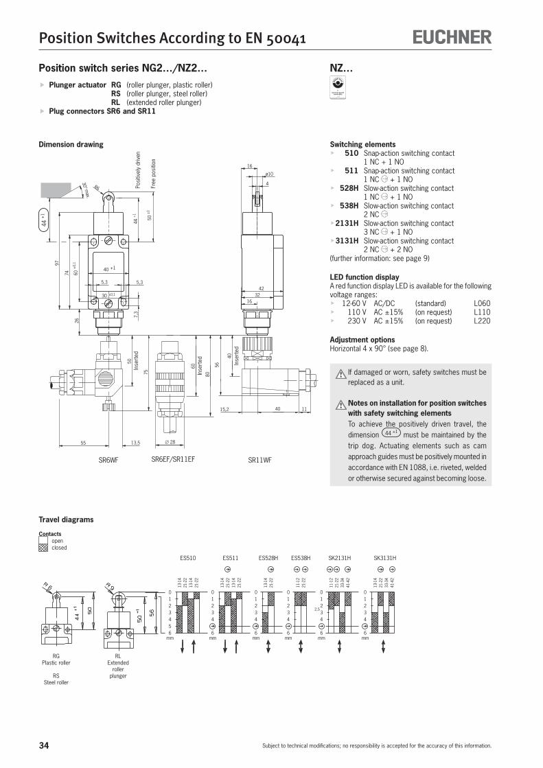
Position switch series NG2…/NZ2…
Switching elementsf 510 Snap-action switching contact
1 NC + 1 NOf 511 Snap-action switching contact
1 NC + 1 NOf 528H Slow-action switching contact
1 NC + 1 NOf 538H Slow-action switching contact
2 NC f 2131H Slow-action switching contact
3 NC + 1 NOf 3131H Slow-action switching contact
2 NC + 2 NO(further information: see page 9)
LED function displayA red function display LED is available for the following voltage ranges:f 12-60 V AC/DC (standard) L060f 110 V AC ±15% (on request) L110f 230 V AC ±15% (on request) L220
Adjustment optionsHorizontal 4 x 90° (see page 8).
If damaged or worn, safety switches must be replaced as a unit.
Notes on installation for position switches with safety switching elements
To achieve the positively driven travel, the dimension 44 +1 must be maintained by the trip dog. Actuating elements such as cam approach guides must be positively mounted in accordance with EN 1088, i.e. riveted, welded or otherwise secured against becoming loose.
4232
16
16
ø10
4
SR11WFSR6WF
55 13,5
50
75
40
56
40 1115,2
SR6EF/SR11EF
∅ 28
60
80
74 60±
0,1
26
40 +1
30 ±0,1
5,3
7,3
R6
97
5,3
50±
1
30° max.
44+
1
44+
1
Posi
tivel
y dr
iven
Free
pos
ition
RGPlastic roller
RSSteel roller
RLExtended
rollerplunger
01234
6
13-1
421
-22
13-1
421
-22
ES511
mm
13-1
421
-22
11-1
221
-22
ES528H ES538H
01234
6mm mm
6
43210
SK2131H
41-4
233
-34
21-2
211
-12
6
43210
41-4
233
-34
21-2
213
-14
SK3131H
mm
01234
6mm
2,5
01234
6
13-1
421
-22
13-1
421
-22
ES510
mm
5
f Plunger actuator RG (roller plunger, plastic roller) RS (roller plunger, steel roller) RL (extended roller plunger)
f Plug connectors SR6 and SR11
NZ…
Dimension drawingIn
sert
ed
Inse
rted Inse
rted
Travel diagrams
Contacts open
closed
35
Position Switches According to EN 50041
Subject to technical modifications; no responsibility is accepted for the accuracy of this information.
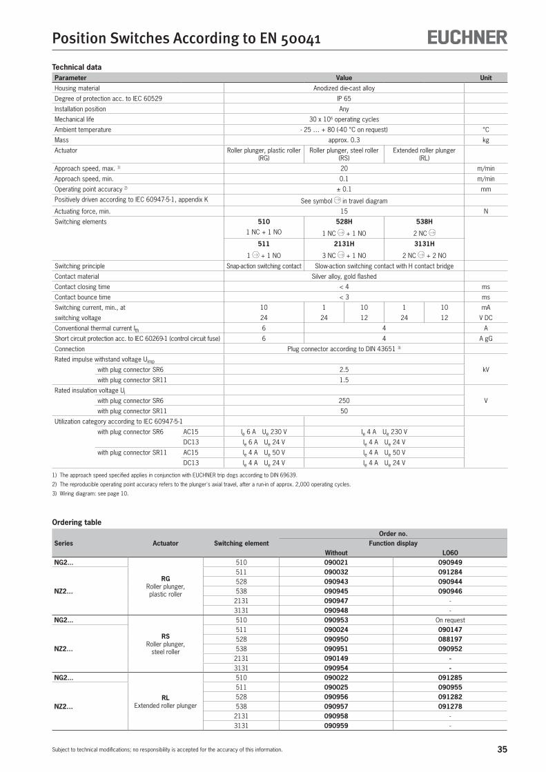
Technical dataParameter Value Unit
Housing material Anodized die-cast alloy
Degree of protection acc. to IEC 60529 IP 65
Installation position Any
Mechanical life 30 x 106 operating cycles
Ambient temperature - 25 … + 80 (-40 °C on request) °C
Mass approx. 0.3 kg
Actuator Roller plunger, plastic roller (RG)
Roller plunger, steel roller (RS)
Extended roller plunger (RL)
Approach speed, max. 1) 20 m/min
Approach speed, min. 0.1 m/min
Operating point accuracy 2) ± 0.1 mm
Positively driven according to IEC 60947-5-1, appendix K See symbol in travel diagram
Actuating force, min. 15 N
Switching elements 510 528H 538H
1 NC + 1 NO 1 NC + 1 NO 2 NC
511 2131H 3131H
1 + 1 NO 3 NC + 1 NO 2 NC + 2 NO
Switching principle Snap-action switching contact Slow-action switching contact with H contact bridge
Contact material Silver alloy, gold flashed
Contact closing time < 4 ms
Contact bounce time < 3 ms
Switching current, min., at 10 1 10 1 10 mA
switching voltage 24 24 12 24 12 V DC
Conventional thermal current Ith 6 4 A
Short circuit protection acc. to IEC 60269-1 (control circuit fuse) 6 4 A gG
Connection Plug connector according to DIN 43651 3)
Rated impulse withstand voltage Uimp
kVwith plug connector SR6 2.5
with plug connector SR11 1.5
Rated insulation voltage Ui
Vwith plug connector SR6 250
with plug connector SR11 50
Utilization category according to IEC 60947-5-1
with plug connector SR6 AC15 Ie 6 A Ue 230 V Ie 4 A Ue 230 V
DC13 Ie 6 A Ue 24 V Ie 4 A Ue 24 V
with plug connector SR11 AC15 Ie 4 A Ue 50 V Ie 4 A Ue 50 V
DC13 Ie 4 A Ue 24 V Ie 4 A Ue 24 V
1) The approach speed specified applies in conjunction with EUCHNER trip dogs according to DIN 69639.
2) The reproducible operating point accuracy refers to the plunger's axial travel, after a run-in of approx. 2,000 operating cycles.
3) Wiring diagram: see page 10.
Ordering table
Series Actuator Switching elementOrder no.
Function displayWithout L060
NG2...
RGRoller plunger, plastic roller
510 090021 090949
NZ2…
511 090032 091284528 090943 090944538 090945 090946
2131 090947 -3131 090948 -
NG2...
RSRoller plunger,
steel roller
510 090953 On request
NZ2…
511 090024 090147528 090950 088197538 090951 090952
2131 090149 -3131 090954 -
NG2...
RLExtended roller plunger
510 090022 091285
NZ2…
511 090025 090955528 090956 091282538 090957 091278
2131 090958 -3131 090959 -

36
Position Switches According to EN 50041
Subject to technical modifications; no responsibility is accepted for the accuracy of this information.
Position switch series NG2…/NZ2…
Switching elementsf 510 Snap-action switching contact
1 NC + 1 NOf 511 Snap-action switching contact
1 NC + 1 NOf 528H Slow-action switching contact
1 NC + 1 NOf 538H Slow-action switching contact
2 NC (further information: see page 9)
LED function displayAvailable on request
Adjustment optionsHorizontal 4 x 90° (see page 8).
If damaged or worn, safety switches must be replaced as a unit.
Notes on installation for position switches with safety switching elements
To achieve the positively driven travel, the dimension 44 +1 must be maintained by the trip dog. Actuating elements such as cam approach guides must be positively mounted in accordance with EN 1088, i.e. riveted, welded or otherwise secured against becoming loose.
16
42
32
74
40 +1
30 ±0,1
5,3
7,3
60±
0,1
22
45°
26,5
31
R6
50±
1
16
∅ 10
4
97
44+
1
30° max.
44+
1
Guide lug aligned
Right-angle plug connector:cable outlet adjustable max. 270°Default setting: cable outlet to the right.
Posi
tivel
y dr
iven
Free
pos
ition
RGPlastic roller
RSSteel roller
RLExtended
rollerplunger
01234
6
13-1
421
-22
13-1
421
-22
ES511
mm
13-1
421
-22
11-1
221
-22
ES528H ES538H
01234
6mm mm
6
43210
SK2131H
41-4
233
-34
21-2
211
-12
6
43210
41-4
233
-34
21-2
213
-14
SK3131H
mm
01234
6mm
2,5
01234
6
13-1
421
-22
13-1
421
-22
ES510
mm
5
f Plunger actuator RG (roller plunger, plastic roller) RS (roller plunger, steel roller) RL (extended roller plunger)
f Plug connector M12/SVM5
NZ…
Dimension drawing
Travel diagrams
Contacts open
closed
37
Position Switches According to EN 50041
Subject to technical modifications; no responsibility is accepted for the accuracy of this information.
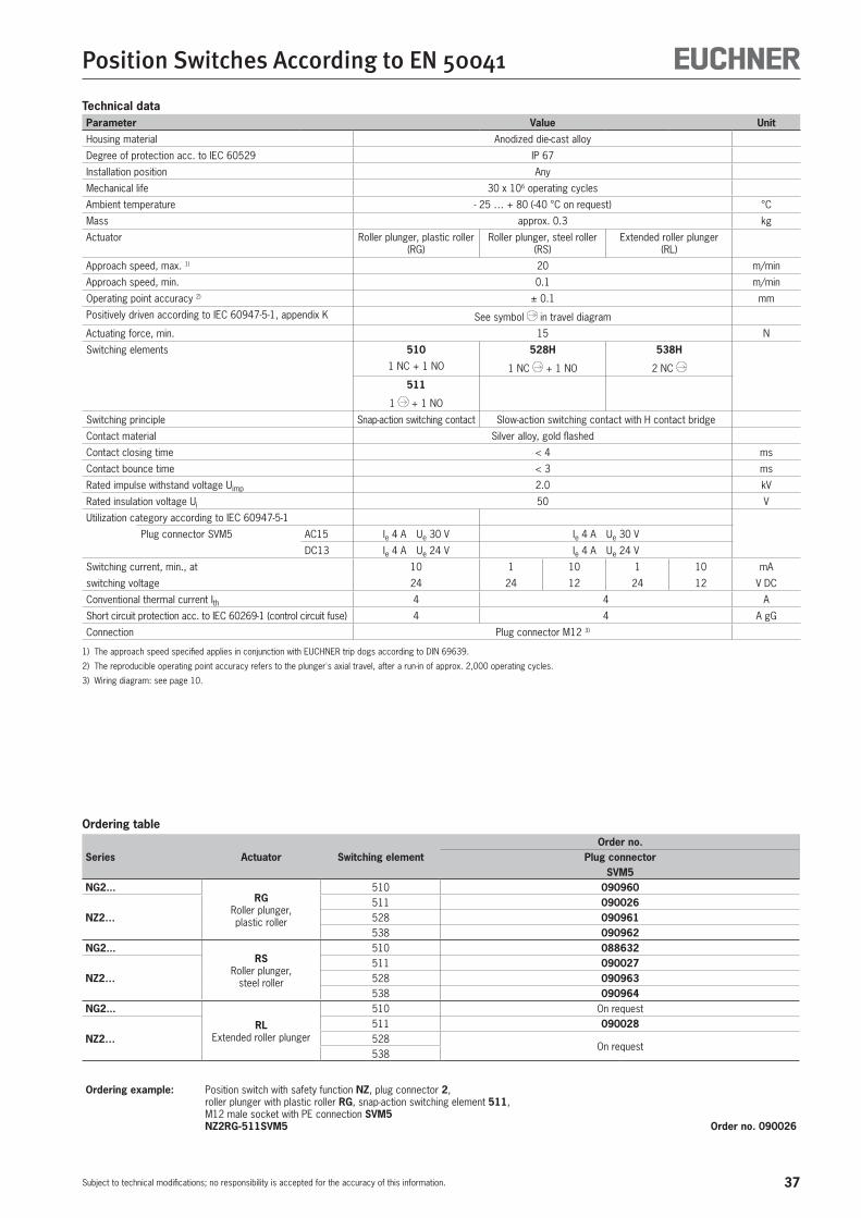
Technical dataParameter Value Unit
Housing material Anodized die-cast alloy
Degree of protection acc. to IEC 60529 IP 67
Installation position Any
Mechanical life 30 x 106 operating cycles
Ambient temperature - 25 … + 80 (-40 °C on request) °C
Mass approx. 0.3 kg
Actuator Roller plunger, plastic roller (RG)
Roller plunger, steel roller (RS)
Extended roller plunger (RL)
Approach speed, max. 1) 20 m/min
Approach speed, min. 0.1 m/min
Operating point accuracy 2) ± 0.1 mm
Positively driven according to IEC 60947-5-1, appendix K See symbol in travel diagram
Actuating force, min. 15 N
Switching elements 510 528H 538H
1 NC + 1 NO 1 NC + 1 NO 2 NC
511
1 + 1 NO
Switching principle Snap-action switching contact Slow-action switching contact with H contact bridge
Contact material Silver alloy, gold flashed
Contact closing time < 4 ms
Contact bounce time < 3 ms
Rated impulse withstand voltage Uimp 2.0 kV
Rated insulation voltage Ui 50 V
Utilization category according to IEC 60947-5-1
Plug connector SVM5 AC15 Ie 4 A Ue 30 V Ie 4 A Ue 30 V
DC13 Ie 4 A Ue 24 V Ie 4 A Ue 24 V
Switching current, min., at 10 1 10 1 10 mA
switching voltage 24 24 12 24 12 V DC
Conventional thermal current Ith 4 4 A
Short circuit protection acc. to IEC 60269-1 (control circuit fuse) 4 4 A gG
Connection Plug connector M12 3)
1) The approach speed specified applies in conjunction with EUCHNER trip dogs according to DIN 69639.
2) The reproducible operating point accuracy refers to the plunger's axial travel, after a run-in of approx. 2,000 operating cycles.
3) Wiring diagram: see page 10.
Ordering table
Series Actuator Switching elementOrder no.
Plug connectorSVM5
NG2...RG
Roller plunger, plastic roller
510 090960
NZ2…511 090026528 090961538 090962
NG2...RS
Roller plunger, steel roller
510 088632
NZ2…511 090027528 090963538 090964
NG2...
RLExtended roller plunger
510 On request
NZ2…511 090028528
On request538
Ordering example: Position switch with safety function NZ, plug connector 2, roller plunger with plastic roller RG, snap-action switching element 511, M12 male socket with PE connection SVM5 NZ2RG-511SVM5 Order no. 090026
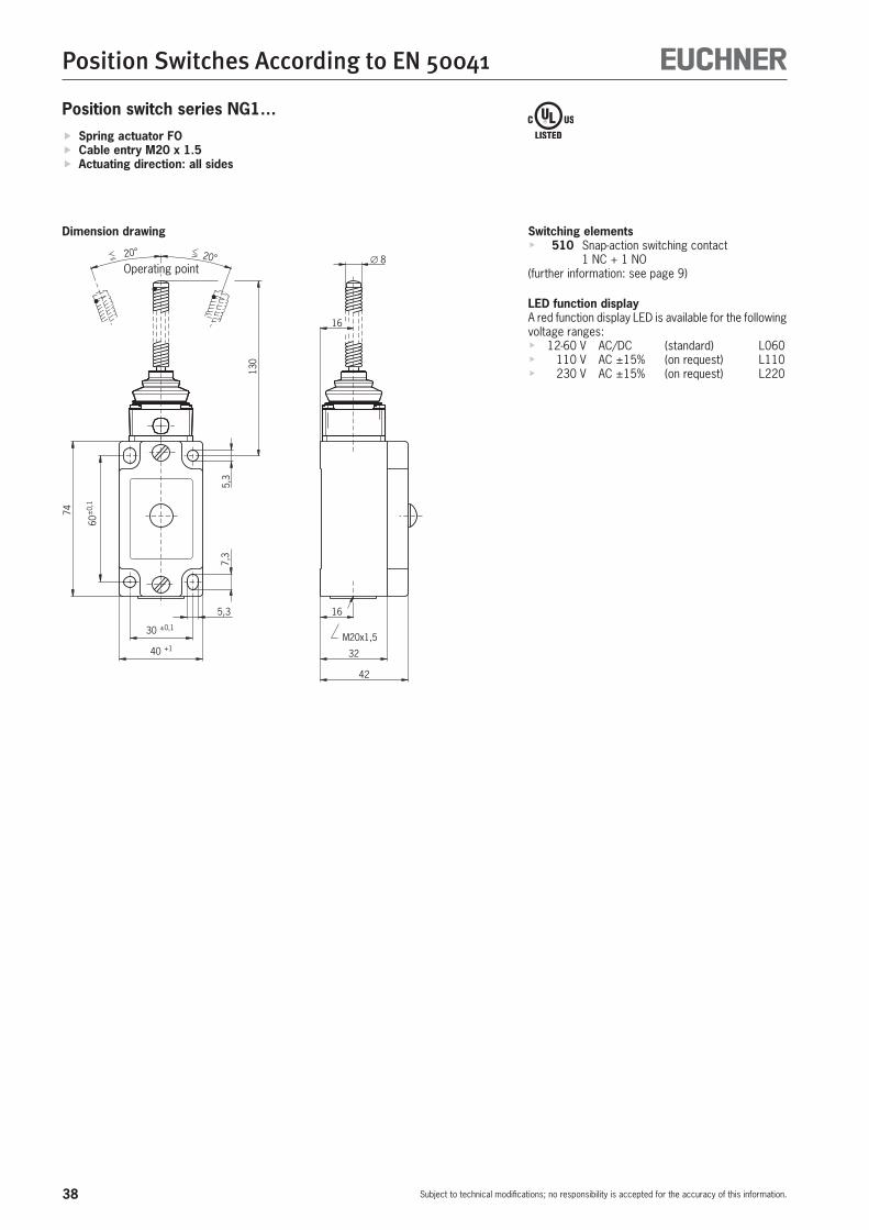
38
Position Switches According to EN 50041
Subject to technical modifications; no responsibility is accepted for the accuracy of this information.
Position switch series NG1…
Switching elementsf 510 Snap-action switching contact
1 NC + 1 NO(further information: see page 9)
LED function displayA red function display LED is available for the following voltage ranges:f 12-60 V AC/DC (standard) L060f 110 V AC ±15% (on request) L110f 230 V AC ±15% (on request) L220
74
5,3
60±
0,1
40 +1
30 ±0,1
16
32
42
M20x1,5
7,3
∅ 820° 20°13
0
16
5,3
Operating point
f Spring actuator FO f Cable entry M20 x 1.5 f Actuating direction: all sides
Dimension drawing

39
Position Switches According to EN 50041
Subject to technical modifications; no responsibility is accepted for the accuracy of this information.
Technical dataParameter Value Unit
Housing material Anodized die-cast alloy
Degree of protection acc. to IEC 60529 IP 67
Installation position Any
Mechanical life 30 x 106 operating cycles
Ambient temperature - 25 … + 80 (-40 °C on request) °C
Mass approx. 0.35 kg
Actuator Spring actuator made of spring steel wire (FO)
Approach speed, max. 20 m/min
Approach speed, min. 0.5 m/min
Actuating force, min. 5 N
Switching elements 510
1 NC + 1 NO
Switching principle Snap-action switching contact
Contact material Silver alloy, gold flashed
Contact closing time < 4 ms
Contact bounce time < 3 ms
Rated impulse withstand voltage Uimp 2.5 kV
Rated insulation voltage Ui 250 V
Utilization category according to IEC 60947-5-1
AC12 Ie 10 A Ue 230 V
AC15 Ie 6 A Ue 230 V
DC13 Ie 6 A Ue 24 V
Switching current, min., at 10 mA
switching voltage 24 V DC
Conventional thermal current Ith 6 A
Short circuit protection acc. to IEC 60269-1 (control circuit fuse) 10/6 A gG
Connection Screw terminal 1)
Conductor cross-section, max. 2 x 1.5 mm²
1) Wiring diagram: see page 9.
Ordering table
Series Actuator Switching elementOrder no.
Function displayWithout L060
NG1…-M FOSpring actuator 510 079911 090029
Ordering example: Position switch without safety function NG, cable entry 1, spring actuator made of spring steel wire FO, snap-action switching element 510, function display L060 10 - 60 V, metric thread M20 x 1.5 M NG1FO-510L060-M Order no. 090 029
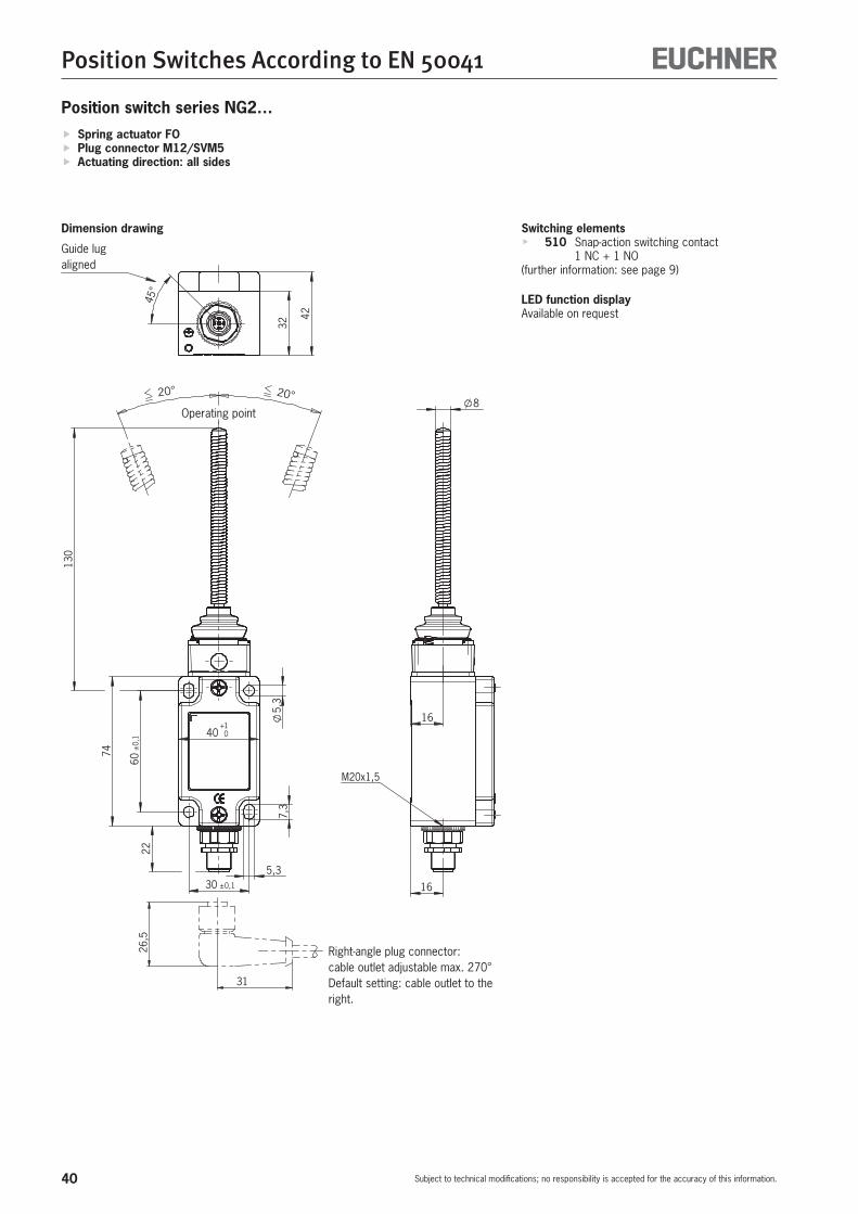
40
Position Switches According to EN 50041
Subject to technical modifications; no responsibility is accepted for the accuracy of this information.
Position switch series NG2…
Switching elementsf 510 Snap-action switching contact
1 NC + 1 NO(further information: see page 9)
LED function displayAvailable on request
8
26,5
31
40 0+1
74
5,3
22
5,3
7,3
30 ±0,1
60±
0,1
130
20°20°
16
16
M20x1,5
32
42
45°
Operating point
Guide lug aligned
Right-angle plug connector:cable outlet adjustable max. 270°Default setting: cable outlet to the right.
f Spring actuator FO f Plug connector M12/SVM5 f Actuating direction: all sides
Dimension drawing

41
Position Switches According to EN 50041
Subject to technical modifications; no responsibility is accepted for the accuracy of this information.
Technical dataParameter Value Unit
Housing material Anodized die-cast alloy
Degree of protection acc. to IEC 60529 IP 67
Installation position Any
Mechanical life 30 x 106 operating cycles
Ambient temperature - 25 … + 80 (-40 °C on request) °C
Mass approx. 0.35 kg
Actuator Spring actuator made of spring steel wire (FO)
Approach speed, max. 20 m/min
Approach speed, min. 0.5 m/min
Actuating force, min. 5 N
Switching elements 510
1 NC + 1 NO
Switching principle Snap-action switching contact
Contact material Silver alloy, gold flashed
Contact closing time < 4 ms
Contact bounce time < 3 ms
Rated impulse withstand voltage Uimp 2.0 kV
Rated insulation voltage Ui 50 V
Utilization category according to IEC 60947-5-1
Plug connector SVM5 AC15 Ie 4 A Ue 30 V
DC13 Ie 4 A Ue 24 V
Switching current, min., at 10 mA
switching voltage 24 V DC
Conventional thermal current Ith 4 A
Short circuit protection acc. to IEC 60269-1 (control circuit fuse) 4 A gG
Connection Plug connector M12 1)
1) Wiring diagram: see page 10.
Ordering table
Series Actuator Switching elementOrder no.
Plug connectorSVM5
NG2... FOSpring actuator 510 092058
Ordering example: Position switch without safety function NG, plug connector 2, spring actuator made of spring steel wire FO, snap-action switching element 510, M12 male socket with PE connection SVM5 NG2FO-510SVM5 Order no. 092 058
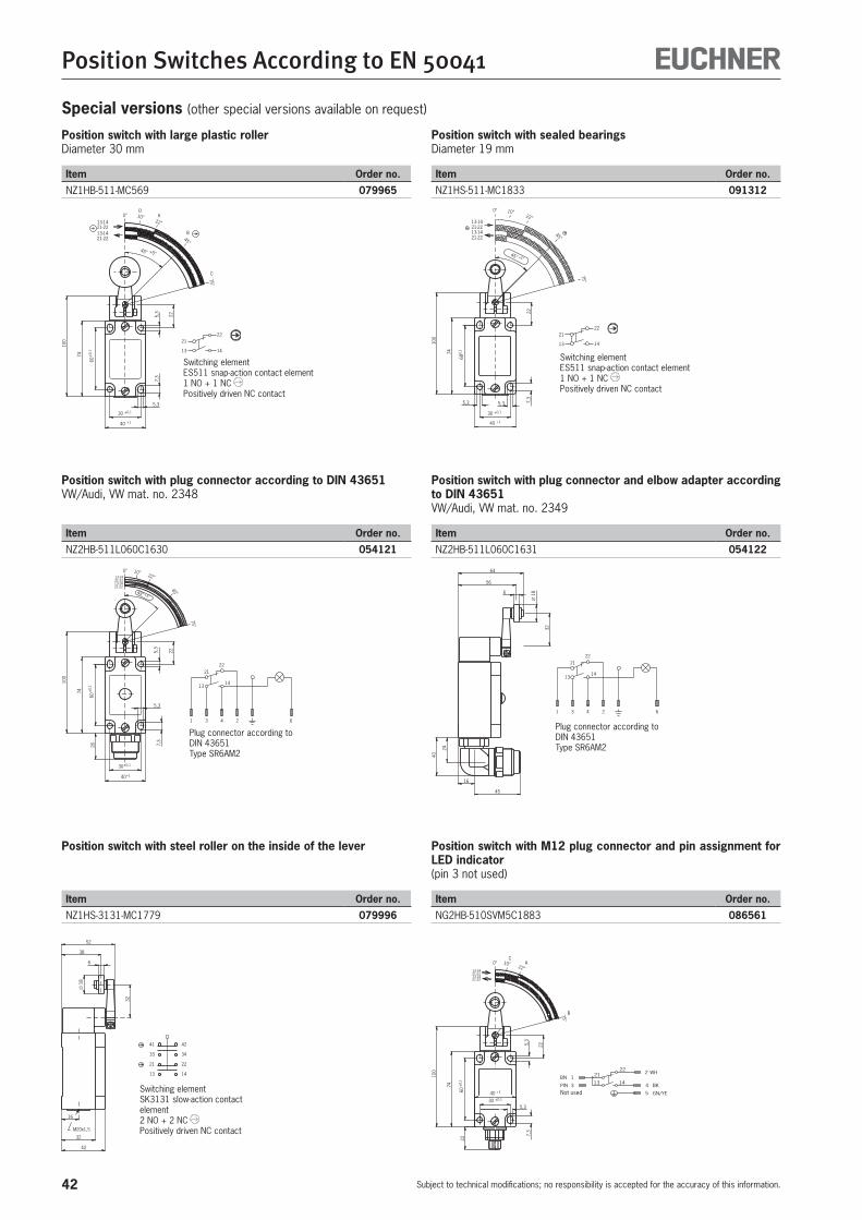
42
Position Switches According to EN 50041
Subject to technical modifications; no responsibility is accepted for the accuracy of this information.
Special versions (other special versions available on request)
Position switch with plug connector according to DIN 43651VW/Audi, VW mat. no. 2348
Item Order no.
NZ2HB-511L060C1630 054121
Plug connector according to DIN 43651Type SR6AM2
21-2213-14
13-1421-22
0°22°
10°
45°
75°
45° +5°
60±
0,1
225,3
7,3
22
5,3
100
74
21
1413
1 3 4 2 6
30±0,1
40+1
26
Position switch with plug connector and elbow adapter according to DIN 43651VW/Audi, VW mat. no. 2349
Item Order no.
NZ2HB-511L060C1631 054122
22
∅18
32
56
64
16
21
1413
1 3 4 2 6
45
6
40
24
Plug connector according to DIN 43651Type SR6AM2
Position switch with large plastic rollerDiameter 30 mm
Item Order no.
NZ1HB-511-MC569 079965
Position switch with sealed bearingsDiameter 19 mm
Item Order no.
NZ1HS-511-MC1833 091312
74
100
5,3
5,3
22
60±
0,1
40 +1
30 ±0,1
7,3
75°
22°10°0°
45°21-2213-1421-2213-14
13
21
14
22
45° +5°
DA
B
C
22
14
21
13
13-1421-2213-1421-22
45°
0° 10°22°
75°
60±0,
1
7,3
5,35,3
22
100
74
30 ±0,1
40 +1
+5°45°
Switching elementES511 snap-action contact element1 NO + 1 NC Positively driven NC contact
Switching elementES511 snap-action contact element1 NO + 1 NC Positively driven NC contact
Position switch with steel roller on the inside of the lever
Item Order no.
NZ1HS-3131-MC1779 079996
Switching elementSK3131 slow-action contact element2 NO + 2 NC Positively driven NC contact
16
32
42
M20x1,5
41 42
33 34
2221
13 14
32
∅18
6
38
52
Position switch with M12 plug connector and pin assignment for LED indicator(pin 3 not used)
Item Order no.
NG2HB-510SVM5C1883 086561
74
100
5,3
7,3
5,3
22
60±
0,1
22
40 +1
30 ±0,1
75°
22°0° 10°
13-1421-2213-1421-22
CA
B
5 GN/YE
PIN 3 BK
WHBN 1
2
4
2221
13 14
Not used

43
Position Switches According to EN 50041
Subject to technical modifications; no responsibility is accepted for the accuracy of this information.
Position switch with protective NBR bellows on the plunger guideProtection against serious contamination and aggressive coolants
Item Order no.
NZ1RS-511-MC1588 091352
Position switch with gold plated contactsFor switching low currents of at least 1 mA
Item Order no.
NZ1RS-510AU-M 090416
74
5,3
60±
0,1
40 +1
30 ±0,1
7,3
48±
1 50±
1
5,3
13
21
14
22
44+
1
Switching elementES511 snap-action contact element1 NO + 1 NC Positively driven NC contact
48±
1 50±
1
R6
97
5,3
30 ±0,1
40 +1
5,3
74
60±
0,1
7,3
M=0,6Nm
Switching element ES510 snap-action contact element1 NO + 1 NCContact material: silver alloy 10 µm electro-gold-platedannular cutting edge contactBreaking capacity max. 30 V / 100 mABreaking capacity min. 5 V / 1 mA
Position switch with sealed bearingsDiameter 16 mm
Item Order no.
NZ1RL-3131-MC1831 089082
Position switch with MENCOM plug connector MIN-9MR-1-18
Item Order no.
NZ1RS-2131-9C-GMMF 077362
5,3
30 ±0,1
40 +1
5,3
97
74
60±
0,1
7,3
41 42
33 34
2221
13 14
50-1
52±
1
53±
1
55±
1
Switching elementSK3131 slow-action contact element2 NO + 2 NC Positively driven NC contact
5,3 5,3
7,3
32
R6
+1
44
50±
1
48±
1
1
97
74
60±
0,1
47,5
±1
40 +1
30 ±0,1
1211
21 22
3433
4241
2
3
1
69
5
8
4
7
1
2
3 4
5
6
78 9
Position switch with 2 LED indicatorsDiameter 18 mm
Item Order no.
NZ1HB-528L024GEGR-M Plastic roller 099929
NZ1HS-528L024GEGR-M Steel roller 099930
40 0+1
30 ±0,1
5,3
7,3
60±
0,1
74
5,3
100
22
45° 0°+5°
45°
0°22°
40°
75°
13 - 1421 - 22
A/D
E B
C
0 V
RD
BN
13
21
14
22
LED YE
LED GN
Switching elementES528 slow-action contact element1 NO + 1 NC Positively driven NC contactOperating voltage for LED indicator:24 V DC, +10%, -15%
LEDyellowLEDgreen

44
Position Switches According to EN 50041
Subject to technical modifications; no responsibility is accepted for the accuracy of this information.
Position switch with small bearingFor high approach speeds and long travel distances
Item Order no.
NZ1RK-528-MC1912 090572
74
5,3
60±
0,1
40 +1
30 ±0,1
7,3
5,3
13
21
14
22
R4
1,5
31+
1
35±
1
37±
1
97
Switching element528 slow-action contact element1 NO + 1 NC Positively driven NC contact
Position switch with steel sleeveFor high approach speeds and protected guidance
Item Order no.
NZ1RS-511-MC782 093141
60±
0,1
30 ±0,1
5048±
1
4401
97
74
Ø5,
37,
3
5,3
40 01
R6
Ø 18
±1
+
+
Switching element511 snap-action contact element1 NO + 1 NC Positively driven NC contact

45
Position Switches According to EN 50041
Subject to technical modifications; no responsibility is accepted for the accuracy of this information.
Accessories
Note:The actuator heads shown are spare parts for position switches without safety function.They do not fit position switches with safety function and must not be operated with these switches.
Rod lever
Item Order no.
NSB (plastic rod) 012052
NSM (aluminum rod) 012053
Lever arm actuation
Item Order no.
NSA 012051
Roller arm
Item Order no.
NHB (plastic roller) 012042
NHS (steel roller) 012043NHSC1834 (ball bearing ∅ 19 mm) 077349
25
M3
Spring actuator
Item Order no.
NFO (spring steel wire) 011909
Adjustable roller arm
Item Order no.
NVB (plastic roller) 012064
NVS (steel roller) 01206525
M3

46
Position Switches According to EN 50041
Subject to technical modifications; no responsibility is accepted for the accuracy of this information.
Note:The actuator heads shown are spare parts for position switches without safety function.They do not fit position switches with safety function and must not be operated with these switches.
Actuator with small roller plunger
Item Order no.
NRK (small steel roller) 012049
Actuator with ball plunger
Item Order no.
NKO (steel ball) 012045
25
M3
25
M3
Actuator with extended roller plunger ∅ 18 mm
Item Order no.
NRL (large steel roller) 012050
Actuator with chisel plunger
Item Order no.
NDO (polish-ground chisel plunger) 011908
25
M3
25
M3
Actuator with roller plunger ∅ 12 mm
Item Order no.
NRG (plastic roller) 012046
NRS (steel roller) 012047
Actuator with domed plunger
Item Order no.
NWO (polish-ground dome) 012066
25
M3
25
M3
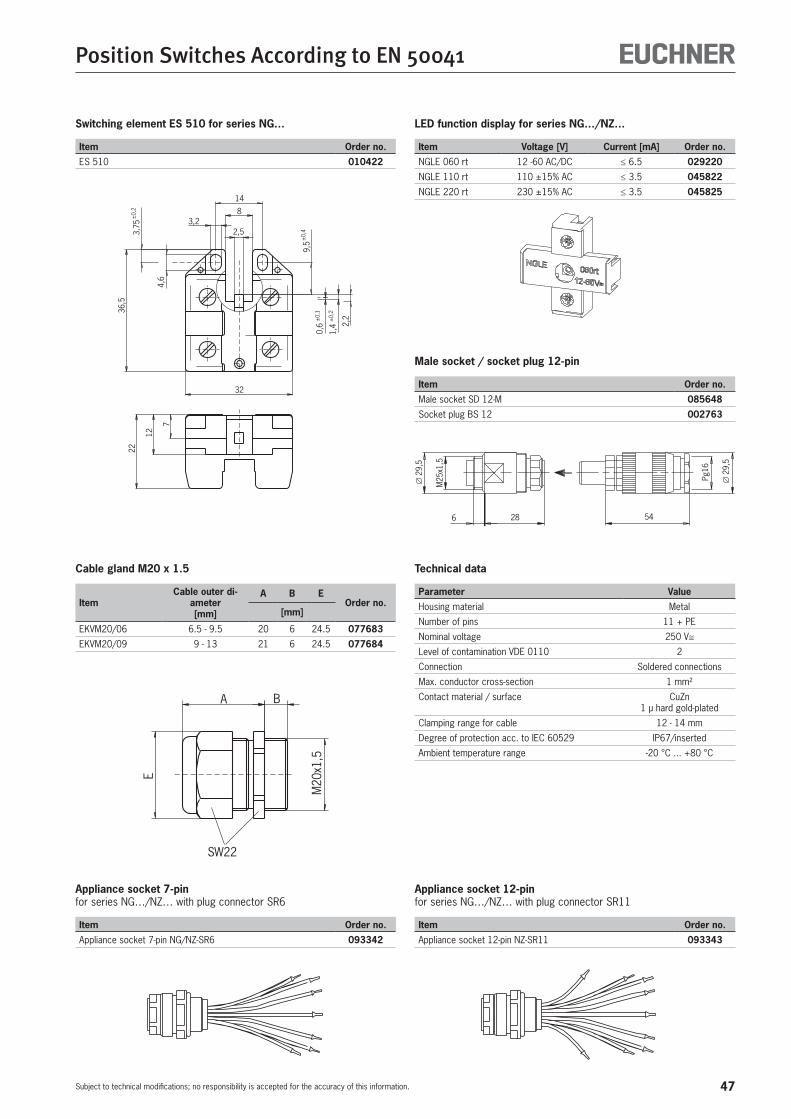
47
Position Switches According to EN 50041
Subject to technical modifications; no responsibility is accepted for the accuracy of this information.
Cable gland M20 x 1.5
ItemCable outer di-
ameter[mm]
A B EOrder no.
[mm]
EKVM20/06 6.5 - 9.5 20 6 24.5 077683
EKVM20/09 9 - 13 21 6 24.5 077684
E
M20
x1,5
BA
SW22
Technical data
Parameter Value
Housing material Metal
Number of pins 11 + PE
Nominal voltage 250 V≅Level of contamination VDE 0110 2
Connection Soldered connections
Max. conductor cross-section 1 mm²
Contact material / surface CuZn1 µ hard gold-plated
Clamping range for cable 12 - 14 mm
Degree of protection acc. to IEC 60529 IP67/inserted
Ambient temperature range -20 °C ... +80 °C
Appliance socket 7-pinfor series NG…/NZ… with plug connector SR6
Item Order no.
Appliance socket 7-pin NG/NZ-SR6 093342
Appliance socket 12-pinfor series NG…/NZ… with plug connector SR11
Item Order no.
Appliance socket 12-pin NZ-SR11 093343
Male socket / socket plug 12-pin
Item Order no.
Male socket SD 12-M 085648
Socket plug BS 12 002763∅
29,5
M25
x1,5
6 28 54
Pg16
∅29
,5
Switching element ES 510 for series NG…
Item Order no.
ES 510 0104227
22
12
32
36,5
4,6
3,75
±0,
2
2,53,2
8
14
9,5
1,4
0,6 2,
2±0,
1
±0,
2
±0,
4
LED function display for series NG…/NZ…
Item Voltage [V] Current [mA] Order no.
NGLE 060 rt 12 -60 AC/DC ≤ 6.5 029220
NGLE 110 rt 110 ±15% AC ≤ 3.5 045822
NGLE 220 rt 230 ±15% AC ≤ 3.5 045825
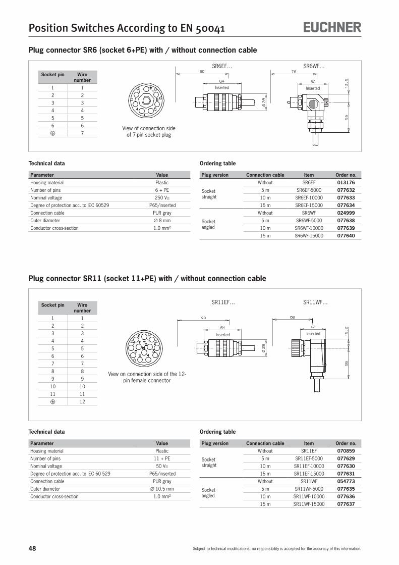
48
Position Switches According to EN 50041
Subject to technical modifications; no responsibility is accepted for the accuracy of this information.
Plug connector SR6 (socket 6+PE) with / without connection cable
Plug connector SR11 (socket 11+PE) with / without connection cable
View on connection side of the 12-pin female connector
SR11EF… SR11WF…
Inserted Inserted
View of connection sideof 7-pin socket plug
SR6EF… SR6WF…
Inserted Inserted
Socket pin Wire number
1 1
2 2
3 3
4 4
5 5
6 6 7
Socket pin Wire number
1 1
2 2
3 3
4 4
5 5
6 6
7 7
8 8
9 9
10 10
11 11 12
Technical data
Parameter Value
Housing material Plastic
Number of pins 6 + PE
Nominal voltage 250 V≅Degree of protection acc. to IEC 60529 IP65/inserted
Connection cable PUR gray
Outer diameter ∅ 8 mm
Conductor cross-section 1.0 mm²
Technical data
Parameter Value
Housing material Plastic
Number of pins 11 + PE
Nominal voltage 50 V≅Degree of protection acc. to IEC 60 529 IP65/inserted
Connection cable PUR gray
Outer diameter ∅ 10.5 mm
Conductor cross-section 1.0 mm²
Ordering table
Plug version Connection cable Item Order no.
Socketstraight
Without SR6EF 013176
5 m SR6EF-5000 077632
10 m SR6EF-10000 077633
15 m SR6EF-15000 077634
Socketangled
Without SR6WF 024999
5 m SR6WF-5000 077638
10 m SR6WF-10000 077639
15 m SR6WF-15000 077640
Ordering table
Plug version Connection cable Item Order no.
Socketstraight
Without SR11EF 070859
5 m SR11EF-5000 077629
10 m SR11EF-10000 077630
15 m SR11EF-15000 077631
Socketangled
Without SR11WF 054773
5 m SR11WF-5000 077635
10 m SR11WF-10000 077636
15 m SR11WF-15000 077637

49
For Your Notes
Subject to technical modifications; no responsibility is accepted for the accuracy of this information.

50
01/1
4
Representatives
Germany
International
ChemnitzEUCHNER GmbH + Co. KGIngenieur- und VertriebsbüroAm Vogelherd 209627 Bobritzsch-HilbersdorfTel. +49 37325 906000Fax +49 37325 [email protected]
DüsseldorfEUCHNER GmbH + Co. KGIngenieur- und VertriebsbüroSundernholz 2445134 EssenTel. +49 201 43083-93Fax +49 201 [email protected]
AustraliaMicromax Sensors & AutomationUnit 2, 106-110 Beaconsfield StreetSilverwater, NSW 2128Tel. +61 2 87482800Fax +61 2 [email protected]
AustriaEUCHNER GmbHSüddruckgasse 42512 TribuswinkelTel. +43 2252 42191Fax +43 2252 [email protected]
BeneluxEUCHNER (BENELUX) BVVisschersbuurt 233356 AE PapendrechtTel. +31 78 615-4766Fax +31 78 [email protected]
BrazilEUCHNER LtdaAv. Prof. Luiz Ignácio Anhaia Mello, no. 4387S. LucasSão Paulo - SP - BrasilCEP 03295-000Tel. +55 11 29182200Fax +55 11 [email protected]
CanadaIAC & Associates Inc.2180 Fasan DriveUnit AOldcastle, OntarioN0R 1L0Tel. +1 519 737-0311Fax +1 519 [email protected]
ChinaEUCHNER (Shanghai) Trading Co., Ltd.No. 8 Workshop A, Hi-Tech Zone503 Meinengda Road Songjiang201613 ShanghaiTel. +86 21 5774-7090Fax +86 21 [email protected]
Czech RepublicEUCHNER electric s.r.o.Videnská 134/10261900 BrnoTel. +420 533 443-150Fax +420 533 [email protected]
Essen/DortmundThomas Kreißlfördern - steuern - regelnHackenberghang 8a45133 Essen Tel. +49 201 84266-0Fax +49 201 [email protected]
WiesbadenEUCHNER GmbH + Co. KGIngenieur- und VertriebsbüroAdolfsallee 368185 WiesbadenTel. +49 611 98817644Fax +49 611 [email protected]
FreiburgEUCHNER GmbH + Co. KGIngenieur- und VertriebsbüroSteige 579206 BreisachTel. +49 7664 4038-33Fax +49 7664 [email protected]
HamburgEUCHNER GmbH + Co. KGIngenieur- und VertriebsbüroBleickenallee 1322763 HamburgTel. +49 40 636740-57Fax +49 40 [email protected]
MagdeburgEUCHNER GmbH + Co. KGIngenieur- und VertriebsbüroTismarstraße 1039108 MagdeburgTel. +49 391 736279-22Fax +49 391 [email protected]
MünchenEUCHNER GmbH + Co. KGIngenieur- und VertriebsbüroObere Bahnhofstraße 682110 GermeringTel. +49 89 800846-85Fax +49 89 [email protected]
NürnbergEUCHNER GmbH + Co. KGIngenieur- und VertriebsbüroSteiner Straße 22a90522 OberasbachTel. +49 911 6693829Fax +49 911 [email protected]
StuttgartEUCHNER GmbH + Co. KGIngenieur- und VertriebsbüroKohlhammerstraße 1670771 Leinfelden-EchterdingenTel. +49 711 7597-0Fax +49 711 [email protected]@euchner.de
DenmarkDuelco A/SSystemvej 89200 Aalborg SVTel. +45 7010 1007Fax +45 7010 [email protected]
FinlandSähkölehto OyHolkkitie 1400880 HelsinkiTel. +358 9 7746420Fax +358 9 [email protected]
FranceEUCHNER France S.A.R.L.Parc d‘Affaires des BellevuesAllée Rosa LuxembourgBâtiment le Colorado95610 ERAGNY sur OISETel. +33 1 3909-9090Fax +33 1 [email protected]
Hong KongImperial Engineers & Equipment Co. Ltd.Unit B 12/F Cheung Lee Industrial Building9 Cheung Lee Street Chai WanHong KongTel. +852 2889 0292Fax +852 2889 [email protected]
HungaryEUCHNER Ges.mbHMagyarországi Fióktelep2045 TörökbálintFSD Park 2.Tel. +36 2342 8374Fax +36 2342 [email protected]
IndiaEUCHNER (India) Pvt. Ltd.401, Bremen Business Center,City Survey No. 2562, University RoadAundh, Pune - 411007Tel. +91 20 64016384Fax +91 20 [email protected]
IsraelIlan & Gavish Automation Service Ltd.26 Shenkar St. Qiryat Arie 49513P.O. Box 10118Petach Tikva 49001Tel. +972 3 9221824Fax +972 3 [email protected]
ItalyTRITECNICA S.p.A.Viale Lazio 2620135 MilanoTel. +39 02 541941Fax +39 02 [email protected]
JapanEUCHNER Representative Office Japan8-20-24 KamitsurumahonchoMinami-ku, Sagamihara-shiKanagawa 252-0318Tel. +81 42 8127767Fax +81 42 [email protected]
Solton Co. Ltd.2-13-7, Shin-YokohamaKohoku-ku, YokohamaJapan 222-0033Tel. +81 45 471-7711Fax +81 45 [email protected]
KoreaEUCHNER Korea Co., Ltd.RM 810 Daerung Technotown 3rd#448 Gasang-DongGumcheon-gu, SeoulTel. +82 2 2107-3500Fax +82 2 [email protected]
MexicoSEPIA S.A. de C.V.Maricopa # 10302, Col. Napoles.Del. Benito Juarez03810 Mexico D.F.Tel. +52 55 55367787Fax +52 55 [email protected]
PolandELTRONPl. Wolnosci 7B50-071 WrocławTel. +48 71 3439755Fax +48 71 [email protected]
Republic of South AfricaRUBICON ELECTRICAL DISTRIBUTORS4 Reith Street, Sidwell6061 Port ElizabethTel. +27 41 451-4359Fax +27 41 [email protected]
RomaniaFirst Electric SRLStr. Ritmului Nr. 1 Bis Ap. 2, Sector 2021675 BucurestiTel. +40 21 2526218Fax +40 21 [email protected]
RussiaVALEX electroUliza Karjer dom 2, Str. 9, Etash 2117449 MoskwaTel. +7 495 41196-35Fax +7 495 [email protected]
SingaporeSentronics Automation & Marketing Pte Ltd.Blk 3, Ang Mo Kio Industrial Park 2A#05-06Singapore 568050Tel. +65 6744 8018Fax +65 6744 [email protected]
SlovakiaEUCHNER electric s.r.o.Videnská 134/10261900 BrnoTel. +420 533 443-150Fax +420 533 [email protected]
SloveniaSMM proizvodni sistemi d.o.o.Jaskova 182000 MariborTel. +386 2 4502326Fax +386 2 [email protected]
SpainEUCHNER, S.L.Gurutzegi 12 - Local 1Polígono Belartza20018 San SebastianTel. +34 943 316-760Fax +34 943 [email protected]
SwedenCensit ABBox 33133123 VärnamoTel. +46 370 691010Fax +46 370 [email protected]
SwitzerlandEUCHNER AGFalknisstrasse 9a7320 SargansTel. +41 81 720-4590Fax +41 81 [email protected]
TaiwanDaybreak Int‘l (Taiwan) Corp.3F, No. 124, Chung-Cheng RoadShihlin 11145, TaipeiTel. +886 2 8866-1234Fax +886 2 [email protected]
TurkeyEUCHNER Endüstriyel Emniyet Teknolojileri Ltd. Şti.Hattat Bahattin Sok.Ceylan Apt. No. 13/AGöztepe Mah.34730 Kadıköy / IstanbulTel. +90 216 359-5656Fax +90 216 [email protected]
United KingdomEUCHNER (UK) Ltd.Unit 2 Petre Drive,SheffieldSouth YorkshireS4 7PZTel. +44 114 2560123Fax +44 114 [email protected]
USAEUCHNER USA Inc.6723 Lyons StreetEast Syracuse, NY 13057Tel. +1 315 701-0315Fax +1 315 [email protected]
EUCHNER USA Inc.Detroit Office130 Hampton CircleRochester Hills, MI 48307Tel. +1 248 537-1092Fax +1 248 [email protected]
www.euchner.com
Support hotline You have technical questions about our products or how they can be used?For further questions please contact your local sales representative.
Comprehensive download area You are looking for more information about our products?You can simply and quickly download operating instructions, CAD or ePLAN data and accompanying software for our products at www.euchner.com.
Customer-specifi c solutionsYou need a specifi c solution or have a special requirement?Please contact us. We can manufacture your custom product even in small quantities.
EUCHNER near youYou are looking for a contact at your location? Along with the headquarters in Leinfel-den-Echterdingen, the worldwide sales network includes 15 subsidiaries and numerous representatives in Germany and abroad – you will defi nitely also fi nd us near you.
U2_U3_EN_2013.indd 2 13.03.13 17:32Adressen neu DE EN FR IT ES.indd 50 20.01.2014 19:17:49
51
www.euchner.com
Support hotline You have technical questions about our products or how they can be used?For further questions please contact your local sales representative.
Comprehensive download area You are looking for more information about our products?You can simply and quickly download operating instructions, CAD or ePLAN data and accompanying software for our products at www.euchner.com.
Customer-specifi c solutionsYou need a specifi c solution or have a special requirement?Please contact us. We can manufacture your custom product even in small quantities.
EUCHNER near youYou are looking for a contact at your location? Along with the headquarters in Leinfel-den-Echterdingen, the worldwide sales network includes 15 subsidiaries and numerous representatives in Germany and abroad – you will defi nitely also fi nd us near you.
U2_U3_EN_2013.indd 2 13.03.13 17:32Adressen neu DE EN FR IT ES.indd 51 20.01.2014 19:17:50
EUCHNER GmbH + Co. KGKohlhammerstraße 1670771 Leinfelden-EchterdingenGermanyTel. +49 711 7597-0Fax +49 711 [email protected]
EN
0766
43-0
8-12
/13
Subj
ect t
o te
chni
cal m
odifi
catio
ns w
ithou
t not
ice,
no
liabi
lity
will
be a
ssum
ed fo
r any
det
ail.
© E
UCH
NER
Gm
bH +
Co.
KG
· TA
Posschalter 50041.indd 1 17.12.13 14:54


