84
POSITIP 8000 Demo User’s Manual Digital Readout English (en) 09/2018

POSITIP 8000 DemoUser’s Manual
Digital Readout
English (en)
09/2018

Contents
2 HEIDENHAIN | POSITIP 8000 Demo | User’s Manual | 09/2018
Contents
1 Fundamentals....................................................................................................................................7
2 Software installation......................................................................................................................11
3 Basic operation............................................................................................................................... 17
4 Software configuration.................................................................................................................. 47
5 Milling – Quick Start...................................................................................................................... 53
6 ScreenshotClient.............................................................................................................................75
7 Index.................................................................................................................................................81
8 List of figures..................................................................................................................................83

Contents
HEIDENHAIN | POSITIP 8000 Demo | User’s Manual | 09/2018 3
1 Fundamentals....................................................................................................................................7
1.1 Overview................................................................................................................................................. 8
1.2 Information on the product.................................................................................................................. 8
1.2.1 Demo software for demonstration of the device functions...................................................... 8
1.2.2 Demo software features............................................................................................................8
1.3 Intended use........................................................................................................................................... 8
1.4 Improper use.......................................................................................................................................... 8
1.5 Notes on reading the documentation................................................................................................. 8
1.6 Symbols and fonts used for marking text.......................................................................................... 9
2 Software installation......................................................................................................................11
2.1 Overview............................................................................................................................................... 12
2.2 Downloading the installation file.......................................................................................................12
2.3 System requirements...........................................................................................................................12
2.4 Installing POSITIP 8000 Demo under Microsoft Windows.............................................................. 13
2.5 Uninstalling POSITIP 8000 Demo.......................................................................................................15
Contents
4 HEIDENHAIN | POSITIP 8000 Demo | User’s Manual | 09/2018
3 Basic operation............................................................................................................................... 17
3.1 Overview............................................................................................................................................... 18
3.2 Using the touchscreen and input devices.........................................................................................18
3.2.1 Touchscreen and input devices............................................................................................... 18
3.2.2 Gestures and mouse actions...................................................................................................19
3.3 General operating elements and functions.......................................................................................21
3.4 POSITIP 8000 Demo – startup and shut-down................................................................................. 23
3.4.1 Starting POSITIP 8000 Demo..................................................................................................23
3.4.2 Shutting down POSITIP 8000 Demo.......................................................................................24
3.5 User login and logout......................................................................................................................... 24
3.5.1 User login.................................................................................................................................24
3.5.2 User logout.............................................................................................................................. 24
3.6 Setting the language........................................................................................................................... 25
3.7 User interface....................................................................................................................................... 25
3.7.1 User interface after Startup..................................................................................................... 25
3.7.2 Main menu of the user interface............................................................................................ 26
3.7.3 Manual operation menu...........................................................................................................28
3.7.4 MDI menu................................................................................................................................30
3.7.5 Program run menu...................................................................................................................33
3.7.6 Programming menu................................................................................................................. 34
3.7.7 File management menu...........................................................................................................37
3.7.8 User login menu...................................................................................................................... 38
3.7.9 Settings menu..........................................................................................................................39
3.7.10 Switch-off menu.......................................................................................................................40
3.8 Position display.................................................................................................................................... 40
3.8.1 Operating elements of the position display............................................................................ 40
3.8.2 Position display functions........................................................................................................ 41
3.9 Status bar............................................................................................................................................. 44
3.9.1 Operating elements of the status bar..................................................................................... 44
3.9.2 Auxiliary functions in Manual operation mode........................................................................ 45
3.10 OEM bar................................................................................................................................................ 46
3.10.1 Operating elements of the OEM bar...................................................................................... 46

Contents
HEIDENHAIN | POSITIP 8000 Demo | User’s Manual | 09/2018 5
4 Software configuration.................................................................................................................. 47
4.1 Overview............................................................................................................................................... 48
4.2 Activating a license key.......................................................................................................................48
4.3 Copying the configuration file............................................................................................................49
4.4 Uploading the configuration data......................................................................................................50
4.5 Setting the language........................................................................................................................... 51
4.6 Selecting the product version (optional)...........................................................................................51
5 Milling – Quick Start...................................................................................................................... 53
5.1 Overview............................................................................................................................................... 54
5.2 Logging in for Quick Start.................................................................................................................. 55
5.3 Requirements........................................................................................................................................56
5.4 Determining the preset (manual operation mode)...........................................................................58
5.5 Machining a through hole (manual operation mode)......................................................................59
5.5.1 Predrilling the through hole..................................................................................................... 59
5.5.2 Boring the through hole...........................................................................................................60
5.6 Machining a rectangular pocket (MDI mode of operation)............................................................. 61
5.6.1 Defining the rectangular pocket.............................................................................................. 62
5.6.2 Milling a rectangular pocket.....................................................................................................63
5.7 Machining a fit (MDI mode of operation)......................................................................................... 64
5.7.1 Defining the fit.........................................................................................................................64
5.7.2 Reaming the fit........................................................................................................................ 65
5.8 Determining the preset (manual operation mode)...........................................................................66
5.9 Programming a bolt hole circle and row of holes (programming)................................................. 68
5.9.1 Creating the program header.................................................................................................. 68
5.9.2 Programming the tool..............................................................................................................69
5.9.3 Programming the bolt hole circle............................................................................................ 69
5.9.4 Programming the tool..............................................................................................................70
5.9.5 Programming the row of holes............................................................................................... 70
5.9.6 Simulating the program run.....................................................................................................71
5.10 Machining a bolt hole circle and row of holes (Program run).........................................................72
5.10.1 Opening the program.............................................................................................................. 72
5.10.2 Running the program...............................................................................................................73

Contents
6 HEIDENHAIN | POSITIP 8000 Demo | User’s Manual | 09/2018
6 ScreenshotClient.............................................................................................................................75
6.1 Overview............................................................................................................................................... 76
6.2 Informationen about ScreenshotClient..............................................................................................76
6.3 Starting ScreenshotClient................................................................................................................... 77
6.4 Connecting ScreenshotClient with the demo software...................................................................77
6.5 Connecting ScreenshotClient with the unit......................................................................................78
6.6 Configuring ScreenshotClient for taking screenshots..................................................................... 78
6.6.1 Configuring the storage location and file name for screenshots.............................................78
6.6.2 Configuring the user interface language of screenshots.........................................................79
6.7 Creating screenshots........................................................................................................................... 80
6.8 Exiting ScreenshotClient..................................................................................................................... 80
7 Index.................................................................................................................................................81
8 List of figures..................................................................................................................................83

1Fundamentals

Fundamentals | Overview 1
8 HEIDENHAIN | POSITIP 8000 Demo | User’s Manual | 09/2018
1.1 Overview
This chapter contains information about the product and these instructions.
1.2 Information on the product
1.2.1 Demo software for demonstration of the device functions
POSITIP 8000 Demo is a software application you can install on a computer
independently of the device. POSITIP 8000 Demo helps you to become familiar
with, try out or present the functions of the device.
1.2.2 Demo software features
Because of the missing hardware environment, the range of features of the demo
software does not correspond to the complete functional range of the device.
However, you can use the descriptions to familiarize yourself with the most
important functions and the user interface.
1.3 Intended use
The products of the POSITIP 8000 series are advanced digital readouts for use on
manually operated machine tools. In combination with linear and angle encoders,
digital readouts of this series return the position of the tool in more than one axis
and provide further functions for operating the machine tool.
POSITIP 8000 Demo is a software product for demonstration of the basic features
of the POSITIP 8000 series products. POSITIP 8000 Demo may be used only for
presentation, training or testing purposes.
1.4 Improper use
POSITIP 8000 Demo is not intended for any use other than the intended use. Any
use for other purposes is prohibited, specifically:
For productive purposes in production systems
As part of production systems
1.5 Notes on reading the documentation
Would you like to see any changes made, or have you found any errors?
We are continuously striving to improve our documentation for you. Please help us
by sending your requests to the following e-mail address:

Fundamentals | Symbols and fonts used for marking text 1
HEIDENHAIN | POSITIP 8000 Demo | User’s Manual | 09/2018 9
1.6 Symbols and fonts used for marking text
In these instructions the following symbols and fonts are used for marking text:
Depiction Meaning
...
...
Identifies an action and the result of this action
Example:
Tap OKThe message is closed
...
...
Identifies an item of a list
Example:
TTL interface
EnDat interface
...
Bold Identifies menus, displays and buttons
Example:
Tap Shut downThe operating system shuts down
Turn the power switch off


2Software
installation

Software installation | Overview 2
12 HEIDENHAIN | POSITIP 8000 Demo | User’s Manual | 09/2018
2.1 Overview
This chapter provides all of the information needed for downloading and properly
installing POSITIP 8000 Demo on a computer.
2.2 Downloading the installation file
Before you can install the demo software on a computer, you need to download an
installation file from the HEIDENHAIN Portal.
To download the installation file from the HEIDENHAIN Portal, you
need access rights to the Software portal folder in the directory of the
appropriate product.
If you do not have access rights to the Portal's Software folder, you can
request the access rights from your HEIDENHAIN contact person.
Download the latest version of POSITIP 8000 Demo here:
www.heidenhain.de
Select the download folder of your browser
Unpack the downloaded file with the extension .zip into a temporary storage
folder
The following files will be unpacked into the temporary storage folder:
Installation file with the extension .exe
File DemoBackup.mcc
2.3 System requirements
If you want to install POSITIP 8000 Demo on a computer, the computer system
must meet the following requirements:
Microsoft Windows 7 or higher
Screen resolution of at least 1280 × 800 recommended
Software installation | Installing POSITIP 8000 Demo under Microsoft Windows 2
HEIDENHAIN | POSITIP 8000 Demo | User’s Manual | 09/2018 13
2.4 Installing POSITIP 8000 Demo under Microsoft
Windows
Select the temporary storage folder into which you unpacked the downloaded
file with the .zip extension
Further information: "Downloading the installation file", Page 12
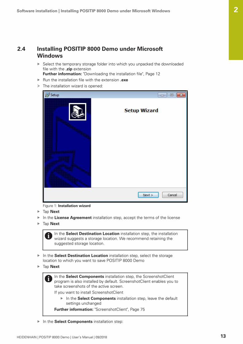
Run the installation file with the extension .exe
The installation wizard is opened:
Figure 1: Installation wizard
Tap Next
In the License Agreement installation step, accept the terms of the license
Tap Next
In the Select Destination Location installation step, the installation
wizard suggests a storage location. We recommend retaining the
suggested storage location.
In the Select Destination Location installation step, select the storage
location to which you want to save POSITIP 8000 Demo
Tap Next
In the Select Components installation step, the ScreenshotClient
program is also installed by default. ScreenshotClient enables you to
take screenshots of the active screen.
If you want to install ScreenshotClient
In the Select Components installation step, leave the default
settings unchanged
Further information: "ScreenshotClient", Page 75
In the Select Components installation step:

Software installation | Installing POSITIP 8000 Demo under Microsoft Windows 2
14 HEIDENHAIN | POSITIP 8000 Demo | User’s Manual | 09/2018
Select the type of installation
Activate or deactivate the option Screenshot Utility
Figure 2: Installation wizard with activated demo software option and Screenshot
Utility
Tap Next
In the Select Start Menu Folder installation step, select the storage location at
which you want to create the start menu folder
Tap Next
In the Select Additional Tasks installation step, select or deselect Desktop
icon
Tap Next
Tap Install
Installation starts—the status of installation is shown in the progress bar
After installation has been completed successfully, use Finish to close the
installation wizard
The program has been successfully installed on your computer

Software installation | Uninstalling POSITIP 8000 Demo 2
HEIDENHAIN | POSITIP 8000 Demo | User’s Manual | 09/2018 15
2.5 Uninstalling POSITIP 8000 Demo
Select in succession in Microsoft Windows:
StartAll programsHEIDENHAIN
POSITIP 8000 Demo
Tap UninstallThe uninstallation wizard opens
To confirm unistallation, tap JaUnistallation starts, and the progress bar indicates the status of the unistallation
process
After uninstallation has been completed successfully, close the uninstallation
wizard with OKThe program has been successfully removed from your computer


3Basic operation

Basic operation | Overview 3
18 HEIDENHAIN | POSITIP 8000 Demo | User’s Manual | 09/2018
3.1 Overview
This chapter describes the user interface, operating elements, and basic functions
of POSITIP 8000 Demo.
3.2 Using the touchscreen and input devices
3.2.1 Touchscreen and input devices
The operating elements on the user interface from POSITIP 8000 Demo are
operated via a touchscreen or a connected mouse.
To enter data, you can use the screen keyboard of the touchscreen or a connected
keyboard.

Basic operation | Using the touchscreen and input devices 3
HEIDENHAIN | POSITIP 8000 Demo | User’s Manual | 09/2018 19
3.2.2 Gestures and mouse actions
To activate, switch or move the operating elements of the user interface, you can
use POSITIP 8000 Demo's touchscreen or a mouse. Gestures are used to operate
the touchscreen and the mouse.
The gestures for operating the touchscreen may differ from the
gestures for operating the mouse.
If the gestures for operating the touchscreen differ from those for
operating the mouse, then these instructions describe both operating
options as alternative actions.
The alternative actions for operating the touchscreen or the mouse are
identified by the following symbols:
Operation using the touchscreen
Operation using the mouse
The following overview describes the different gestures for operating the
touchscreen or the mouse:
Tapping
Means touching the screen briefly with your fingertip
Means pressing the left mouse button once
The actions initiated by tapping include
Selection of menus, features or parameters
Entering characters with the screen keyboard
Closing dialogs
Holding (long press)
Means touching the screen and holding your finger(s) on it for a
few seconds
Means pressing the left mouse button once and holding it
down
The actions initiated by holding are
Quickly changing the values in input fields with plus and
minus buttons
Basic operation | Using the touchscreen and input devices 3
20 HEIDENHAIN | POSITIP 8000 Demo | User’s Manual | 09/2018
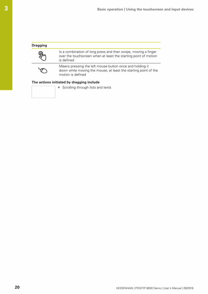
Dragging
Is a combination of long press and then swipe, moving a finger
over the touchscreen when at least the starting point of motion
is defined
Means pressing the left mouse button once and holding it
down while moving the mouse; at least the starting point of the
motion is defined
The actions initiated by dragging include
Scrolling through lists and texts

Basic operation | General operating elements and functions 3
HEIDENHAIN | POSITIP 8000 Demo | User’s Manual | 09/2018 21
3.3 General operating elements and functions
The operating elements described below are available for configuration and
operating the product via the touchscreen or input devices.
Screen keyboard
With the screen keyboard, you can enter text into the input fields of the user
interface. The displayed screen keyboard is either numeric or alphanumeric,
depending on the input field.
To enter values, tap an input field
The input field is highlighted
The screen keyboard is displayed
Enter text or numbers
In some input fields, a green check mark indicates that the entry is correct
If the entry is incomplete or incorrect, a red exclamation mark is displayed. The
entry cannot be concluded in this case
To apply the values, confirm the entry with RETThe values are displayed
The screen keyboard disappears
Input fields with plus and minus buttons
To adjust a numerical value, use the + (plus) and – (minus) buttons to the left and
right of the numerical value.
Tap + or – until the desired value is displayed
Long-press + or – to scroll through the values more
quickly
The selected value is displayed
Toggle switch
Use the toggle switch to switch between functions.
Tap the desired function
The active function is shown in green
The inactive function is shown in light gray
Slide switch
With the sliding switch, you can activate or deactivate a function.
Drag the sliding switch to the desired position or tap the
sliding switch
The function is activated or deactivated
Drop-down list
Buttons that open drop-down lists are indicated by a triangle pointing down.
Tap the button
The drop-down list opens
The active entry is highlighted in green
Tap the desired entry
The selected entry is applied

Basic operation | General operating elements and functions 3
22 HEIDENHAIN | POSITIP 8000 Demo | User’s Manual | 09/2018
Undo
With this button, you can undo the last action.
Processes that have already been concluded cannot be undone.
Tap UndoThe last action is undone
Add
To add a feature, tap AddThe new feature is added
Close
Tap Close to close a dialog
Confirm
Tap Confirm to conclude an activity
Back
Tap Back to return to the higher level in the menu
structure

Basic operation | POSITIP 8000 Demo – startup and shut-down 3
HEIDENHAIN | POSITIP 8000 Demo | User’s Manual | 09/2018 23
3.4 POSITIP 8000 Demo – startup and shut-down
3.4.1 Starting POSITIP 8000 Demo
Before using POSITIP 8000 Demo, you need to perform the steps for
configuring the software.
Tap POSITIP 8000 Demo on the Microsoft Windows desktop
or
Select in succession in Microsoft Windows:
StartAll programsHEIDENHAIN
POSITIP 8000 Demo
Two executable files with different modes of
appearance are available:
POSITIP 8000 Demo: starts within a Microsoft
Windows window
POSITIP 8000 Demo (full screen): starts in
full-screen mode
Tap POSITIP 8000 Demo or
POSITIP 8000 Demo (full screen)
POSITIP 8000 Demo starts an output window in the
background. The output window is not relevant for operation
and is closed again when POSITIP 8000 Demo is shut down
POSITIP 8000 Demo starts the user interface with the Userlogin menu
Figure 3: User login menu

Basic operation | POSITIP 8000 Demo – startup and shut-down 3
24 HEIDENHAIN | POSITIP 8000 Demo | User’s Manual | 09/2018
3.4.2 Shutting down POSITIP 8000 Demo
Tap Switch off in the main menu
Tap Shut downPOSITIP 8000 Demo is shut down
To shut down POSITIP 8000 Demo in the Microsoft Windows window,
also use the Switch-off menu.
If you use Close to close the Microsoft Windows window, all settings
will be lost.
3.5 User login and logout
In the User login menu, you can log in and out of the product as a user.
Only one user can be logged in to the product at a time. The logged-in user is
displayed. Before a new user can log in, the logged-in user has to log out.
The product provides various authorization levels that grant the user full
or restricted access to management and operation functionality.
3.5.1 User login
Tap User login in the main menu
In the drop-down list, select the OEM user
Tap the Password input field
Enter the password "oem" of the OEM user
Confirm entry with RETTap Log inThe user is logged in and the Manual operation menu is
displayed
3.5.2 User logout
Tap User login in the main menu
Tap Log outThe user is logged out
All functions of the main menu are inactive, except for SwitchoffThe product can only be used again after a user has logged in

Basic operation | Setting the language 3
HEIDENHAIN | POSITIP 8000 Demo | User’s Manual | 09/2018 25
3.6 Setting the language
The default language for the user interface is English. You can switch the user
interface to the desired language.
Tap Settings in the main menu
Tap UserThe logged-in user is indicated by a check mark
Select the logged-in user
The language selected for the user is indicated by a national
flag in the Language drop-down list
Select the flag for the desired language in the Languagedrop-down list
The user interface is displayed in the selected language
3.7 User interface
The unit is available in different versions, which are variously equipped.
The user interface and available functions may vary depending on the
version.
3.7.1 User interface after Startup
User interface after startup
If automatic user login is active and the last user who logged in was of the
Operator type, the Manual operation menu is displayed after the product has
started up.
If automatic user login is not active, the product opens the User login menu.
Further information: "User login menu", Page 38

Basic operation | User interface 3
26 HEIDENHAIN | POSITIP 8000 Demo | User’s Manual | 09/2018
3.7.2 Main menu of the user interface
User interface (in Manual operation mode)
1
2
Figure 4: User interface (in Manual operation mode)
1 Message display area, displays the time and the number of unclosed messages
2 Main menu with operating elements
Operating elements of the main menu
The main menu is displayed independently of activated software options.
Operating
element
Function
3 MessageDisplay of an overview of all messages as well as the
number of messages that have not been closed
Manual operationManual positioning of machine axes
Further information: "Manual operation menu",
Page 28
MDI modeDirect input of the desired axis movements (Manual Data
Input); the distance-to-go is calculated and displayed
Further information: "MDI menu", Page 30
Program runExecution of a previously created program with operator
guidance
Further information: "Program run menu", Page 33
ProgrammingCreation and management of individual programs
Further information: "Programming menu", Page 34

Basic operation | User interface 3
HEIDENHAIN | POSITIP 8000 Demo | User’s Manual | 09/2018 27
Operating
element
Function
File managementManagement of the files that are available on the product
Further information: "File management menu",
Page 37
User loginLogin and logout of the user
Further information: "User login menu", Page 38
SettingsSettings of the product, such as setting up users, configur-
ing sensors or updating the firmware
Further information: "Settings menu ", Page 39
Switch-offShutdown of the operating system or activation of energy-
saving mode
Further information: "Switch-off menu", Page 40

Basic operation | User interface 3
28 HEIDENHAIN | POSITIP 8000 Demo | User’s Manual | 09/2018
3.7.3 Manual operation menu
Activation
Tap Manual operation in the main menu
The user interface for manual operation is displayed
Manual operation menu (in the Milling application mode)
1
4
2
5
3
Figure 5: Manual operation menu in the milling application mode
1 Axis key
2 Reference
3 Position display
4 Status bar
5 Spindle speed (machine tool)

Basic operation | User interface 3
HEIDENHAIN | POSITIP 8000 Demo | User’s Manual | 09/2018 29
Manual operation menu (in the Turning application mode)
1
5
4
32
Figure 6: Manual operation menu in the turning application mode
1 Axis key
2 Reference
3 Position display
4 Status bar
5 Spindle speed (machine tool)
In the Manual operation menu, the workspace shows the position values
measured at the machine axes.
The status bar provides auxiliary functions.

Basic operation | User interface 3
30 HEIDENHAIN | POSITIP 8000 Demo | User’s Manual | 09/2018
3.7.4 MDI menu
Activation
Tap MDI in the main menu
MDI mode menu (in the Milling application mode)
1 32
4
5
Figure 7: MDI mode menu in the milling application mode
1 Axis key
2 Actual position
3 Distance-to-go
4 Status bar
5 Spindle speed (machine tool)

Basic operation | User interface 3
HEIDENHAIN | POSITIP 8000 Demo | User’s Manual | 09/2018 31
MDI mode menu (in the Turning application mode)
1 42
5
6
3
Figure 8: MDI mode menu in the turning application mode
1 Axis key
2 Actual position
3 Coupled axes
4 Distance-to-go
5 Status bar
6 Spindle speed (machine tool)

Basic operation | User interface 3
32 HEIDENHAIN | POSITIP 8000 Demo | User’s Manual | 09/2018
MDI block dialog
Tap MDI in the main menu
Tap Create on the status bar
The user interface for the MDI mode is displayed
1 32
4
5
Figure 9: MDI block dialog
1 View bar
2 Block parameters
3 MDI block
4 Status bar
5 Block tools
The MDI (Manual Data Input) menu enables you to enter the desired axis
movements directly. You specify the distance to the target point, and the distance
to go is then calculated and displayed.
The status bar provides additional measured values and functions.

Basic operation | User interface 3
HEIDENHAIN | POSITIP 8000 Demo | User’s Manual | 09/2018 33
3.7.5 Program run menu
Activation
Tap Program run in the main menu
The user interface for program run is displayed
Program run menu (in the Milling application mode)
1
2
5 34
Figure 10: Program run menu in the milling application mode
1 View bar
2 Status bar
3 Program control
4 Spindle speed (machine tool)
5 Program management

Basic operation | User interface 3
34 HEIDENHAIN | POSITIP 8000 Demo | User’s Manual | 09/2018
Program run menu (in the Turning application mode)
1
2
5 34
Figure 11: Program run menu in the turning application mode
1 View bar
2 Status bar
3 Program control
4 Spindle speed (machine tool)
5 Program management
The Program run menu makes it possible to execute a program that has
previously been created in the Programming operating mode. During execution, a
wizard will guide you through the individual program steps.
You can display a visualization of the selected block in the optional simulation
window.
The status bar provides additional measured values and functions.
3.7.6 Programming menu
Activation
Tap Programming in the main menu
The user interface for programming is displayed
The status bar and the optional OEM bar are not available in the
Programming menu.

Basic operation | User interface 3
HEIDENHAIN | POSITIP 8000 Demo | User’s Manual | 09/2018 35
Programming menu (in the Milling application mode)
1 2
3
Figure 12: Programming menu in the milling application mode
1 View bar
2 Toolbar
3 Program management
You can display a visualization of the selected block in the optional simulation
window.
1 42
5
3
6
Figure 13: Programming menu with simulation window opened
1 View bar
2 Simulation window (optional)
3 Block parameters
4 Toolbar
5 Program blocks
6 Program management

Basic operation | User interface 3
36 HEIDENHAIN | POSITIP 8000 Demo | User’s Manual | 09/2018
Programming menu (in the Turning application mode)
1 2
3
Figure 14: Programming menu in the turning application mode
1 View bar
2 Toolbar
3 Program management
You can display a visualization of the selected block in the optional simulation
window.
1 42
5
3
6
Figure 15: Programming menu with simulation window opened
1 View bar
2 Simulation window (optional)
3 Block parameters
4 Toolbar
5 Program blocks
6 Program management

Basic operation | User interface 3
HEIDENHAIN | POSITIP 8000 Demo | User’s Manual | 09/2018 37
In the Programming menu, you can create and manage programs. You define
individual machining steps or machining patterns as blocks. A sequence of blocks
then forms a program.
3.7.7 File management menu
Activation
Tap File management in the main menu
The user interface for file management is displayed
Short description
12
Figure 16: File management menu
1 List of available storage locations
2 List of folders in the selected storage location
The File management menu shows an overview of the files stored in the
product's memory.

Basic operation | User interface 3
38 HEIDENHAIN | POSITIP 8000 Demo | User’s Manual | 09/2018
3.7.8 User login menu
Activation
Tap User login in the main menu
The user interface for user login and logout is displayed
Short description
1
2
Figure 17: User login menu
1 Display of the logged-in user
2 User login
The User login menu shows the logged-in user in the column on the left. The login
of a new user is displayed in the column on the right.
To log in another user, the logged-in user must log out.
Further information: "User login and logout", Page 24

Basic operation | User interface 3
HEIDENHAIN | POSITIP 8000 Demo | User’s Manual | 09/2018 39
3.7.9 Settings menu
Activation
Tap Settings in the main menu
The user interface for the device settings is displayed
Short description
1 2
Figure 18: Settings menu
1 List of setting options
2 List of setting parameters
The Settings menu shows all options for configuring the product. With the setting
parameters, you can adapt the product to on-site requirements.
The product provides various authorization levels that grant the user full
or restricted access to management and operation functionality.

Basic operation | User interface 3
40 HEIDENHAIN | POSITIP 8000 Demo | User’s Manual | 09/2018
3.7.10 Switch-off menu
Activation
Tap Switch off in the main menu
The operating elements for shutting down the operating
system, for activating the energy-saving mode and for
activating the cleaning mode are displayed
Short description
The Switch off menu provides the following options:
Operating
element
Function
Shut downShuts down POSITIP 8000 Demo
Energy saving modeSwitches the screen off and puts the operating system into
energy-saving mode
Cleaning modeSwitches the screen off; the operating system continues
unchanged
Further information: "POSITIP 8000 Demo – startup and shut-down", Page 23
3.8 Position display
The unit’s position display shows the axis positions and additional information
about the configured axes (if applicable).
You can also couple the display of axes and have access to the spindle functions.
3.8.1 Operating elements of the position display
Symbol Meaning
XAxis key
Axis key functions:
Tapping the axis key: opens input field for position value
(Manual mode) or dialog MDI block (MDI mode)
Holding down the axis key: sets the current position as zero
point
Dragging the axis key to the right: opens menu if functions
are available for the axis
XIn the turning application mode: The position display shows the
diameter of the radial machining axis X
RReference mark search performed successfully
RReference mark search not performed or no reference mark
detected

Basic operation | Position display 3
HEIDENHAIN | POSITIP 8000 Demo | User’s Manual | 09/2018 41
Symbol Meaning
+ZZo axis is coupled with the Z axis. Position display shows the
sum of both position values
Further information: "Coupling of axes (in the Turning applica-
tion mode)", Page 41
Z axis is coupled with the Zo axis. Position display shows the
sum of both position values
1Selected gear stage of the gear spindle
Further information: "Setting the gear stage for gear spindles",
Page 42
Spindle speed cannot be achieved with selected gear stage
Select a higher gear stage
Spindle speed cannot be achieved with selected gear stage
Select a lower gear stage
The CSS (constant surface speed) spindle mode is activated
Further information: "Setting the spindle mode (in the Turning
application mode)", Page 43
If the icon is flashing, then the calculated spindle speed lies
outside of the defined speed range. The desired surface speed
cannot be attained. The spindle will continue to turn at the
maximum or minimum speed
In MDI mode and Program Run , a scaling factor is applied to
the axis
Axis is feedback-controlled
3.8.2 Position display functions
Coupling of axes (in the Turning application mode)
In the Turning application mode, you can alternately couple the display of the Zaxis and the Zo axis. For coupled axes, the position display shows the sum of the
position values of both axes.
If the Z axis and the Zo axis have been coupled, the Program run
operating mode is disabled.
Coupling is identical for the Z axis and Zo axis. The following describes
only the coupling of the Z axis.
Coupling axes
ZIn the working space, drag the Z axis key to the right
Tap CoupleThe Zo axis is now coupled with the Z axis
+Z The icon for the coupled axes is shown next to the Z axis keyThe position value for the coupled axes is shown as a sum

Basic operation | Position display 3
42 HEIDENHAIN | POSITIP 8000 Demo | User’s Manual | 09/2018
Decoupling axes
ZIn the working space, drag the Z axis key to the right
Tap DecoupleThe position value of both axes are shown independently of
each other
Setting the spindle speed
You can control the spindle speed depending on the configuration of the
connected machine tool.
Tap or long-press + or – to set the spindle speed to the
desired value
or
Tap the Spindle speed input field, enter the value and tap
RET to confirm
The product applies the entered spindle speed as the
nominal value and controls the spindle of the machine tool
accordingly
Setting the gear stage for gear spindles
If your machine tool uses a gear spindle, then you can select the gear stage used.
The selection of the gear stages can also be controlled via an external
signal.
SIn the working space, drag the S axis key to the right
Tap Gear stageThe Set gear stage dialog appears
Tap the desired gear stage
Tap ConfirmThe selected gear stage is now adopted as the new value
Drag the S axis key to the left
1 The icon for the selected gear stage appears next to the Saxis key
If the desired spindle speed cannot be attained with the selected gear
stage, then the gear stage icon will flash with an upward pointing arrow
(higher gear stage) or with a downward pointing arrow (lower gear
stage).

Basic operation | Position display 3
HEIDENHAIN | POSITIP 8000 Demo | User’s Manual | 09/2018 43
Setting the spindle mode (in the Turning application mode)
In the Turning application mode, you can decide whether the unit uses the
standard speed mode or CSS (constant surface speed) for the spindle mode.
In the CSS spindle mode, the unit calculates the spindle speed such that the
surface speed of the turning tool remains constant regardless of the workpiece
geometry.
Activating the CSS spindle mode
SIn the working space, drag the S axis key to the right
Tap CSS modeThe Activate CSS dialog appears
Enter the value for Maximum spindle speedTap ConfirmThe CSS spindle mode is activated
The spindle speed is shown in the unit of measure m/minDrag the S axis key to the left
The icon for the CSS spindle mode appears next to the S axiskey
Activating the speed mode
SIn the working space, drag the S axis key to the right
Tap Speed modeThe Activate speed mode dialog appears
Enter the value for Maximum spindle speedTap ConfirmThe speed mode is activated
The spindle speed is shown in the unit of measure rpmDrag the S axis key to the left

Basic operation | Status bar 3
44 HEIDENHAIN | POSITIP 8000 Demo | User’s Manual | 09/2018
3.9 Status bar
The status bar and the optional OEM bar are not available in the
Programming menu.
The status bar displays the feed rate and the traversing speed. The operating
elements of the status bar also give you direct access to the preset table and tool
table, as well as to the stopwatch and calculator features.
3.9.1 Operating elements of the status bar
The status bar provides the following operating elements:
Operating
element
Function
Quick access menuFor setting the units of measure for linear and angular
values, configuring a scaling factor, and configuring the
position display for radial machining axes (in the Turningapplication mode); tapping it opens the quick access menu
Preset tableDisplay of the current preset; tapping opens the preset
table
Tool tableDisplay of the current tool; tapping opens the tool table
StopwatchTime display with Start / Stop function in h:mm:ss format
CalculatorCalculator with the most important mathematical functions,
speed calculator, and taper calculator
Feed rateDisplay of the actual feed rate of the currently fastest axis
The feed-rate value can be set in the Manual operation and
MDI operating modes; tapping it opens the feed-rate menu
OverrideDisplay of the changed traversing speed of an axis. The
change is made using an external controller on an NC-
controlled machine tool
Auxiliary functionsAuxiliary functions in Manual operation mode, depending
on the configured application mode
MDI blockFor creating machining blocks in MDI mode

Basic operation | Status bar 3
HEIDENHAIN | POSITIP 8000 Demo | User’s Manual | 09/2018 45
3.9.2 Auxiliary functions in Manual operation mode
Depending on the configured application mode, the following operating elements
are available:
Operating
element
Function
Reference marksFor starting the reference mark search
ProbingFor probing the edge of a workpiece
ProbingFor finding the centerline of a workpiece
ProbingFor finding the center point of a circular feature (hole or
cylinder)
PresetsFor setting presets
Tool dataFor tool setting (touch-off)

Basic operation | OEM bar 3
46 HEIDENHAIN | POSITIP 8000 Demo | User’s Manual | 09/2018
3.10 OEM bar
The status bar and the optional OEM bar are not available in the
Programming menu.
The optional OEM bar allows you to control the configuration of the functions of
the connected machine tool, independently of its configuration.
3.10.1 Operating elements of the OEM bar
The operating elements that are available on the OEM bar depend on
the configuration of the device and of the connected machine tool.
The OEM bar usually provides the following operating elements:
Operating
element
Function
LogoDisplays the configured OEM logo
Spindle speedDisplays one or more values that have been predefined for
the spindle speed of a connected NC-controlled machine
tool

4Software
configuration

Software configuration | Overview 4
48 HEIDENHAIN | POSITIP 8000 Demo | User’s Manual | 09/2018
4.1 Overview
Make sure that you have read and understood the "Basic operation"
chapter before carrying out the actions described below.
Further information: "Basic operation", Page 17
Before you can use POSITIP 8000 Demo correctly after successful installation, you
need to configure POSITIP 8000 Demo. This chapter describes how to perform the
following settings:
Activating a license key
Copying the configuration file
Uploading the configuration data
Setting the language
Selecting the product version (optional)
4.2 Activating a license key
With POSITIP 8000 Demo, you can also simulate functions that are dependent on
a software option. To do so, you must enable the software option with a license
key. The required license key is stored in a license file in the folder structure of
POSITIP 8000 Demo.
You must upload the license file in order to enable the available software options.
Tap Settings in the main menu
The unit’s settings appear
Tap ServiceOpen in the sequence
Software optionsActivate optionsTap Read license file
Select the storage location in the dialog:
Select Internal
Select User
Select the PcDemoLicense.xml license file
Confirm your selection with OKTap OKThe license key is activated
Tap OKYou are prompted to restart
Use Cancel to deny restarting
The functions dependent on the software options are
available
Software configuration | Copying the configuration file 4
HEIDENHAIN | POSITIP 8000 Demo | User’s Manual | 09/2018 49
4.3 Copying the configuration file
Before you can load the configuration data in POSITIP 8000 Demo, you must first
copy the downloaded configuration file DemoBackup.mcc to an area that can be
accessed by POSITIP 8000 Demo.
Move to the temporary storage folder
For example, copy the configuration file DemoBackup.mcc to the following
folders:C: HEIDENHAIN [product name] Mom ProductsMGE5
[product designation] user User
In order for POSITIP 8000 Demo to access the configuration file
DemoBackup.mcc, you must retain the following part of the path
when you save the file: [product name] ProductsMGE5 Mom
[product abbreviation] user User.
The configuration file can be accessed by POSITIP 8000 Demo

Software configuration | Uploading the configuration data 4
50 HEIDENHAIN | POSITIP 8000 Demo | User’s Manual | 09/2018
4.4 Uploading the configuration data
Before you can upload the configuration data, you must first activate
the license key.
Further information: "Activating a license key", Page 48
In order to configure POSITIP 8000 Demo for the application on the computer,
you must upload the configuration file DemoBackup.mcc.
Tap Settings in the main menu
The product settings are displayed
Figure 19: Settings menu
Tap ServiceOpen in the sequence
Back up and restoreRestore settingsComplete restoration
Select the storage location in the dialog:
InternalUser
Select the DemoBackup.mcc configuration file
Confirm your selection with OKThe settings are applied
You are prompted to shut down the application
Tap OKPOSITIP 8000 Demo is shut down, and the Microsoft
Windows window is closed
Restart POSITIP 8000 Demo
POSITIP 8000 Demo is ready for use

Software configuration | Setting the language 4
HEIDENHAIN | POSITIP 8000 Demo | User’s Manual | 09/2018 51
4.5 Setting the language
The default language for the user interface is English. You can switch the user
interface to the desired language.
Tap Settings in the main menu
Tap UserThe logged-in user is indicated by a check mark
Select the logged-in user
The language selected for the user is indicated by a national
flag in the Language drop-down list
Select the flag for the desired language in the Languagedrop-down list
The user interface is displayed in the selected language
4.6 Selecting the product version (optional)
POSITIP 8000 is available in different versions. These versions differ in their
interfaces for connectible encoders:
In the Settings menu, you can select the version that is to be simulated with
POSITIP 8000 Demo
Tap Settings in the main menu
Tap ServiceTap Product designationSelect the desired version
You are now prompted to perform a restart
POSITIP 8000 Demo is ready for use in the desired version


5Milling – Quick
Start

Milling – Quick Start | Overview 5
54 HEIDENHAIN | POSITIP 8000 Demo | User’s Manual | 09/2018
5.1 Overview
This chapter describes the machining of an example workpiece and will guide you
step by step through the unit’s different operating modes. You need to carry out
the following machining steps for successful production of the flange:
Machining step Mode of operation
Determine preset 0 Manual operation
Machine a through hole Manual operation
Machine a rectangular pocket MDI mode
Machine a fit MDI mode
Determine preset 1 Manual operation
Machine a bolt hole circle Programming and program run
Machine a row of holes Programming and program run
The machining steps described here cannot be completely simulated
with POSITIP 8000 Demo. However, you can use the descriptions to
familiarize yourself with the most important functions and the user
interface.
Figure 20: Example workpiece
This chapter does not describe machining of the outside contour of the example
workpiece. It is presumed that the outside contour is already machined.
For a detailed description of the individual activities, please refer
to the "Manual operation" and "MDI mode" chapters as well as the
"Programming" and "Program run" chapters in the operating instructions
POSITIP 8000.
Make sure that you have read and understood the "Basic operation"
chapter before carrying out the actions described below.
Further information: "Basic operation", Page 17

Milling – Quick Start | Logging in for Quick Start 5
HEIDENHAIN | POSITIP 8000 Demo | User’s Manual | 09/2018 55
5.2 Logging in for Quick Start
User login
For Quick Start, the Operator user must log in.
Tap User login in the main menu
If required, log out the user who is currently logged in
Select the Operator user
Tap the Password input field
Enter the password "operator”
If the password does not match the default
password, ask a Setup user or OEM user for the
assigned password.
If the password is no longer known, contact a
HEIDENHAIN service agency.
Confirm entry with RETTap Log in

Milling – Quick Start | Requirements 5
56 HEIDENHAIN | POSITIP 8000 Demo | User’s Manual | 09/2018
5.3 Requirements
To manufacture the aluminum flange, use a manually operated or NC-controlled
machine tool. The following dimensioned technical drawing is available for the
flange:
A-A
Ø20
H6
Ø6.
1
13
10
M6
20
6
Ø50±0.05
100
90±0.05
80±0.1
45±
0.05
45±
0.05
95±
0.05
90±
0.05
145
110±
0.05
25±
0.05
AA
45°
8x45°(=360°)
R6
1x45°
Figure 21: Example workpiece– technical drawing
Machine tool
The machine tool is switched on
A pre-processed workpiece blank is clamped on the machine tool
Product
A spindle axis is configured
The axes have been homed
A HEIDENHAINKT 130 Edge Finder is available

Milling – Quick Start | Requirements 5
HEIDENHAIN | POSITIP 8000 Demo | User’s Manual | 09/2018 57
Tools
The following tools are available:
Drill Ø 5.0 mm
Drill Ø 6.1 mm
Drill Ø 19.8 mm
Reamer Ø 20 mm H6
End mill Ø 12 mm
Countersink Ø 25 mm 90°
Tap M6
Tool table
For the example it is presumed that the tools for machining are not yet defined.
For each tool used, you must therefore define the specific parameters in the tool
table of the product. During subsequent machining you can access the parameters
in the tool table via the status bar.
Tap Tools on the status bar
The Tools dialog appears
Tap Open tableThe Tool table dialog appears
Tap AddIn the Tool type input field enter the name Drill 5.0Confirm the entry with RETIn the Diameter input field, enter the value 5.0Confirm the entry with RETIn the Length input field enter the length of the drill
Confirm the entry with RETThe defined Ø 5.0 mm drill is added to the tool table
Repeat the sequence for the other tools using the naming
convention [type] [diameter]Tap CloseThe Tool table dialog is closed

Milling – Quick Start | Determining the preset (manual operation mode) 5
58 HEIDENHAIN | POSITIP 8000 Demo | User’s Manual | 09/2018
5.4 Determining the preset (manual operation mode)
Initially you need to determine the first preset. Based on this preset the product
then calculates all values for the relative coordinate system. Ascertain the preset
with the HEIDENHAIN KT 130 Edge Finder.
D1: 0/0
Figure 22: Example workpiece – finding preset D1
Activation
Tap Manual operation in the main menu
The user interface for manual operation is displayed
Probing the preset D1
On the machine tool, insert the HEIDENHAINKT 130 Edge
Finder into the spindle and connect it to the product
Tap Auxiliary functions in the status bar
In the dialog, tap Probe edgeThe Select the tool dialog box appears
In the Select the tool dialog, activate the Use touch probeoption
Follow the wizard's instructions and define the preset by
probing in the X direction
Move the edge finder toward the workpiece edge until the
red LED on the edge finder lights up
The Select preset dialog box opens
Retract the edge finder from the workpiece edge
In the Selected preset field, select the preset 0 from the
preset table
In the Set position values field enter the value 0 for the X
direction and confirm with RETTap Confirm in the wizard
The probed coordinate is loaded in preset 0Repeat the procedure and define the preset in the Y direction
via probing

Milling – Quick Start | Machining a through hole (manual operation mode) 5
HEIDENHAIN | POSITIP 8000 Demo | User’s Manual | 09/2018 59
5.5 Machining a through hole (manual operation mode)
In the first machining step you drill the through hole in manual operation mode
using the Ø 5.0 mm drill. You then drill the through hole with the Ø 19.8 mm
drill. The values to be entered into the input fields can be taken directly from the
dimensioned production drawing.
95
50
Figure 23: Example workpiece – drilling a through hole
Activation
Tap Manual operation in the main menu
The user interface for manual operation is displayed
5.5.1 Predrilling the through hole
On the machine tool, insert the Ø 5.0 mm drill into the
spindle
Tap Tools on the status bar
The Tools dialog appears
Tap Drill 5.0Tap ConfirmThe associated tool parameters are applied automatically
The Tools dialog is closed
On the product, set a spindle speed of 3500 rpm
On the machine tool move the spindles as follows:
X direction: 95 mm
Y direction: 50 mm
Predrill the through hole and retract the spindle
Keep positions X and Y
You have successfully predrilled the through hole

Milling – Quick Start | Machining a through hole (manual operation mode) 5
60 HEIDENHAIN | POSITIP 8000 Demo | User’s Manual | 09/2018
5.5.2 Boring the through hole
On the machine tool, insert the Ø 19.8 mm drill into the
spindle
Tap Tools on the status bar
The Tools dialog appears
Tap Drill 19.8Tap ConfirmThe associated tool parameters are applied automatically
The Tools dialog is closed
On the product, set a spindle speed of 400 rpm
Bore the through hole and retract the spindle
You have successfully bored the through hole

Milling – Quick Start | Machining a rectangular pocket (MDI mode of operation) 5
HEIDENHAIN | POSITIP 8000 Demo | User’s Manual | 09/2018 61
5.6 Machining a rectangular pocket (MDI mode of
operation)
Machine the rectangular pocket in MDI mode of operation. The values to be
entered into the input fields can be taken directly from the dimensioned production
drawing.
Figure 24: Example workpiece – machining a rectangular pocket
Activation
Tap MDI in the main menu
The user interface for the MDI mode is displayed

Milling – Quick Start | Machining a rectangular pocket (MDI mode of operation) 5
62 HEIDENHAIN | POSITIP 8000 Demo | User’s Manual | 09/2018
5.6.1 Defining the rectangular pocket
Tap Tools on the status bar
The Tools dialog appears
Tap End millTap ConfirmThe associated tool parameters are applied automatically
The Tools dialog is closed
ZMove the tool until it touches the surface of the flange
Hold down Z in the position display
The product displays 0 with the Z axis
Tap Create on the status bar
A new block is displayed
Select the Rectangular pocket block type in the Block typedrop-down list
Enter the following parameters according to the dimensional
data:
Clearance height: 10
Depth: -6
X coordinate of center: 80
Y coordinate of center: 50
Side length in X: 110
Side length in Y: 80
Direction: clockwise
Finishing allowance: 0.2
If the tool axis is NC-controlled, additionally enter the
following parameters:
Starting depth: 0.5
Plunging depth: 4
Feed rate for milling: 800
Feed rate for plunging: 260
Confirm each entry with RETTo run the block, tap ENDThe positioning aid is displayed
If the simulation window is active, the rectangular pocket is
visualized

Milling – Quick Start | Machining a rectangular pocket (MDI mode of operation) 5
HEIDENHAIN | POSITIP 8000 Demo | User’s Manual | 09/2018 63
5.6.2 Milling a rectangular pocket
The values for spindle speed, milling depth and feed rate depend on the
end mill's metal-removal rate and the machine tool.
On the machine tool, insert the Ø 12 mm end mill into the
spindle
On the product, set the spindle speed to a suitable value
If the product or the machine tool has NC-controlled axes, tap
or press the NC START key
Start the machining process—follow the instructions of the
wizard
The product executes the individual steps of the milling
operation
Tap CloseProgram run is terminated
The wizard closes
You have successfully machined the rectangular pocket

Milling – Quick Start | Machining a fit (MDI mode of operation) 5
64 HEIDENHAIN | POSITIP 8000 Demo | User’s Manual | 09/2018
5.7 Machining a fit (MDI mode of operation)
Machine the fit in MDI mode of operation. The values to be entered into the input
fields can be taken directly from the dimensioned production drawing.
You should chamfer the through hole before reaming. The chamfer
enables a better first cut of the reamer and prevents burr formation.
Figure 25: Example workpiece – machining a fit
Activation
Tap MDI in the main menu
The user interface for the MDI mode is displayed
5.7.1 Defining the fit
Tap Tools on the status bar
The Tools dialog appears
Tap ReamerTap ConfirmThe associated tool parameters are applied automatically
The Tools dialog is closed
Tap Create on the status bar
A new block is displayed
Select the Positioning block type in the Block type drop-
down list
Enter the following parameters according to the dimensional
data:
X coordinate: 95
Y coordinate: 50
Z coordinate: drill through
If the tool axis is NC-controlled, enter the following
parameters:
Z coordinate: –25
Confirm each entry with RETTo run the block, tap ENDThe positioning aid is displayed
If the simulation window is active, the position and traverse
path are visualized

Milling – Quick Start | Machining a fit (MDI mode of operation) 5
HEIDENHAIN | POSITIP 8000 Demo | User’s Manual | 09/2018 65
5.7.2 Reaming the fit
On the machine tool, insert the Ø 20 mm H6 reamer into the
spindle
If the product or the machine tool has NC-controlled axes, tap
or press the NC START key
On the product, set a spindle speed of 250 rpm
Start the machining process—follow the instructions of the
wizard
Tap CloseProgram run is terminated
The wizard closes
You have successfully machined the fit

Milling – Quick Start | Determining the preset (manual operation mode) 5
66 HEIDENHAIN | POSITIP 8000 Demo | User’s Manual | 09/2018
5.8 Determining the preset (manual operation mode)
To align the bolt hole circle and frame of holes you must set the circle center of
the fit as the preset. Based on this preset the product then calculates all values for
the relative coordinate system. Ascertain the preset with the HEIDENHAIN KT 130
Edge Finder.
D2: 0/0
Figure 26: Example workpiece – finding preset D2
Activation
Tap Manual operation in the main menu
The user interface for manual operation is displayed
Probing preset D2
On the machine tool, insert the HEIDENHAIN KT 130 Edge
Finder into spindle and connect to the product
Tap Auxiliary functions in the status bar
Tap Find circle center in the dialog
The Select the tool dialog box opens
In the Select the tool dialog, activate the Use touch probeoption
Follow the instructions of the wizard
Move the edge finder toward the workpiece edge until the
red LED on the edge finder lights up
The Select preset dialog box opens
Retract the edge finder from the workpiece edge
In the Selected preset field, select preset 1In the Set position values field, enter the value 0 for position
value X and position value Y and confirm with RETTap Confirm in the wizard
The probed coordinates are loaded in preset 1

Milling – Quick Start | Determining the preset (manual operation mode) 5
HEIDENHAIN | POSITIP 8000 Demo | User’s Manual | 09/2018 67
Activating the preset
Tap Presets on the status bar
The Presets dialog box opens
Tap preset 1Tap ConfirmThe preset is set
On the status bar 1 is displayed with preset

Milling – Quick Start | Programming a bolt hole circle and row of holes (programming) 5
68 HEIDENHAIN | POSITIP 8000 Demo | User’s Manual | 09/2018
5.9 Programming a bolt hole circle and row of holes
(programming)
Machine the bolt hole circle and row of holes in Programming mode of operation.
You may be able to reuse the program in a small batch production. The values
to be entered into the input fields can be taken directly from the dimensioned
production drawing.
Figure 27: Example workpiece – programming a bolt hole pattern and a row of holes
Activation
Tap Programming in the main menu
The user interface for programming is displayed
5.9.1 Creating the program header
Tap Create new program in the program management
A dialog box is opened.
In the dialog select the storage location, e.g.
Internal/Programs in which you want to save the program
Enter a name for the program
Confirm the entry with RETTap CreateA new program containing the Program header start block is
created
In Name enter the name ExampleConfirm the entry with RETIn Unit for linear values select the mm unit of measure
The program has been successfully created; you can then
begin with programming

Milling – Quick Start | Programming a bolt hole circle and row of holes (programming) 5
HEIDENHAIN | POSITIP 8000 Demo | User’s Manual | 09/2018 69
5.9.2 Programming the tool
Tap Add block on the toolbar
A new block is inserted below the current position
In the Block type drop-down list, select the Tool call block
type
Tap Tool numberThe Tools dialog appears
Tap Drill 6.1The associated tool parameters are applied automatically
The Tools dialog is closed
Tap Add block on the toolbar
A new block is inserted below the current position
In the Block type drop-down list, select the Spindle speedblock type
In Spindle speed, enter the value 3000Confirm the entry with RET
5.9.3 Programming the bolt hole circle
Tap Add block on the toolbar
A new block is inserted below the current position
Select the Bolt hole circle block type in the Block type drop-
down list
Enter the following values:
Number of holes: 8
X coordinate of center: 0
Y coordinate of center: 0
Radius: 25
Starting angle: 0°
Stepping angle: full circle
Depth: –25
If the tool axis is NC-controlled, additionally enter the
following parameters:
Clearance height: 10
Feed rate: 2000
Feed rate for plunging: 600
Confirm each entry with RETTap END to terminate the input process
Tap Save program in the program management
The program is saved

Milling – Quick Start | Programming a bolt hole circle and row of holes (programming) 5
70 HEIDENHAIN | POSITIP 8000 Demo | User’s Manual | 09/2018
5.9.4 Programming the tool
Tap Add block on the toolbar
A new block is inserted below the current position
In the Block type drop-down list, select the Tool call block
type
Tap Tool numberThe Tools dialog appears
Tap Drill 5.0The associated tool parameters are applied automatically
The Tools dialog is closed
Tap Add block on the toolbar
A new block is inserted below the current position
In the Block type drop-down list, select the Spindle speedblock type
In Spindle speed, enter the value 3000Confirm the entry with RET
5.9.5 Programming the row of holes
Tap Add block on the toolbar
A new block is inserted below the current position
Select the Row of holes block type in the Block type drop-
down list
Enter the following values:
X coordinate of 1st hole: -90
Y coordinate of 1st hole: -45
Holes per row: 4
Hole spacing: 45
Angle: 0°
Depth: -13
Number of rows: 3
Row spacing: 45
Fill mode: frame of holes
If the tool axis is NC-controlled, additionally enter the
following parameters:
Clearance height: 10
Feed rate: 2000
Feed rate for plunging: 600
Confirm each entry with RETTap Save program in the program management
The program is saved

Milling – Quick Start | Programming a bolt hole circle and row of holes (programming) 5
HEIDENHAIN | POSITIP 8000 Demo | User’s Manual | 09/2018 71
5.9.6 Simulating the program run
After successfully programming the bolt hole circle and row of holes you can then
simulate the sequence of the program created with the simulation window.
Figure 28: Example workpiece – simulation window
Tap Simulation windowThe simulation window is displayed
Tap each program block, one after the other
The tapped machining step is shown in color in the
simulation window
Check the view for programming errors, e.g. tool path
intersections of holes
If there are no programming errors you can machine the bolt
hole circle and row of holes

Milling – Quick Start | Machining a bolt hole circle and row of holes (Program run) 5
72 HEIDENHAIN | POSITIP 8000 Demo | User’s Manual | 09/2018
5.10 Machining a bolt hole circle and row of holes (Program
run)
You have defined the single machining steps for bolt hole circle and row of holes in
a program. You can execute the created program in Program run.
Figure 29: Example workpiece – drilling a bolt hole pattern and a row of holes
5.10.1 Opening the program
Tap Program run on the product in the main menu
The user interface for program run is displayed
Tap Open program in the program management
A dialog box is opened.
Select the Internal/Programs storage location in the dialog
Tap the file Example.iTap OpenThe selected program is opened

Milling – Quick Start | Machining a bolt hole circle and row of holes (Program run) 5
HEIDENHAIN | POSITIP 8000 Demo | User’s Manual | 09/2018 73
5.10.2 Running the program
On the machine tool, insert the Ø 6.1 mm drill into the
spindle
Tap NC START on the program control
or
On the machine tool: Press the NC START keyThe product selects the first tool call block of the program
The wizard displays the relevant instructions
Tap NC START again to begin machining
or
On the machine tool: Press the NC START keyThe spindle speed is set and the first machining block for bolt
hole circle is selected
The single steps of the bolt hole circle machining block are
displayed
Tap NC START to move the axis
or
On the machine tool: Press the NC START keyA movement is executed
Depending on the machine tool, carry out user intervention,
e.g. manually move the Z axis when drilling through
Call the next step of the bolt hole circle machining block with
NextThe next step is called
Tap NC START to execute the next movement
or
On the machine tool: Press the NC START keyFollow the instructions of the wizard
After executing all steps in the bolt hole circle machining
block, tap Next program stepThe next machining block, row of holes, is selected
The single steps of the row of holes machining block are
displayed
On the machine tool, insert the Ø 5.0 mm drill into the
spindle
Repeat the process for the row of holes machining block
After drilling the row of holes tap CloseThe machining is terminated
The program is reset
The wizard is closed


6ScreenshotClient

ScreenshotClient | Overview 6
76 HEIDENHAIN | POSITIP 8000 Demo | User’s Manual | 09/2018
6.1 Overview
The standard installation of POSITIP 8000 Demo also contains the
ScreenshotClient program. With ScreenshotClient, you can take screenshots of
the demo software or the unit.
This chapter describes how ScreenshotClient is configured and used.
6.2 Informationen about ScreenshotClient
With ScreenshotClient, you can take screenshots of the active screen of the
demo software or the unit from a computer. Before taking a screenshot, select the
desired user interface language, as well as the file name and the location where
you want to store the screenshots.
ScreenshotClient creates image files of the desired screen:
In .PNG format
With the configured name
With the appropriate language code
With the time information of year, month, day, hour, minute, and second
1
2
4
3
Figure 30: ScreenshotClient user interface
1 Connection status
2 File path and file name
3 Language selection
4 Status messages

ScreenshotClient | Starting ScreenshotClient 6
HEIDENHAIN | POSITIP 8000 Demo | User’s Manual | 09/2018 77
6.3 Starting ScreenshotClient
Select in succession in Microsoft Windows:
StartAll programsHEIDENHAIN
POSITIP 8000 Demo
ScreenshotClientScreenshotClient is started:
Figure 31: ScreenshotClient has been started (not connected yet)
You can now connect ScreenshotClient with the demo software or the product
6.4 Connecting ScreenshotClient with the demo software
Before establishing a connection with ScreenshotClient, first start the
demo software or switch on the unit. Otherwise ScreenshotClient will
show the status message Connection close. when trying to connect.
Start the demo software if you have not already done so
Further information: "Starting POSITIP 8000 Demo", Page 23
Tap ConnectA connection with the demo software is established
The status message is updated
The Identifier and Language input fields become active

ScreenshotClient | Connecting ScreenshotClient with the unit 6
78 HEIDENHAIN | POSITIP 8000 Demo | User’s Manual | 09/2018
6.5 Connecting ScreenshotClient with the unit
Prerequisite: The network must be configured on the device.
For detailed information on configuring the network at the unit, please
refer to the “Setup” chapter in the operating instructions of POSITIP
8000.
Before establishing a connection with ScreenshotClient, first start the
demo software or switch on the unit. Otherwise ScreenshotClient will
show the status message Connection close. when trying to connect.
Switch on the unit if you have not already done so
Enter the IPv4 address of the interface in the Connection input field.
You will find the address in the unit settings under:
Interfaces ► Network ► X116Tap ConnectA connection with the unit is established
The status message is updated
The Identifier and Language input fields become active
6.6 Configuring ScreenshotClient for taking screenshots
Once you have started ScreenshotClient, you can make the following
configurations:
Location at which screenshots are stored, and what the file names are
User interface language in which the screenshots are created
6.6.1 Configuring the storage location and file name for screenshots
By default, ScreenshotClient saves screenshots to the following storage location:
C: HEIDENHAIN [product designation] ProductsMGE5 Mom
[product code] sources [file name]
You can define a different storage location, if necessary.
Tap the Identifier input field
Enter the path to the storage location and the name for the screenshots into
the Identifier input field
Use the following syntax to enter the path and file name for
screenshots:
[drive]:\[folder]\[file name]
ScreenshotClient will save all screenshots to the storage location entered

ScreenshotClient | Configuring ScreenshotClient for taking screenshots 6
HEIDENHAIN | POSITIP 8000 Demo | User’s Manual | 09/2018 79
6.6.2 Configuring the user interface language of screenshots
The Language input field shows all of the user interface languages available
for the demo software or the unit. Once you have selected a language code,
ScreenshotClient will take screenshots in the corresponding language.
The user interface language you are using in the demo software or on
the unit does not have any effect on the screenshots. Screenshots
are always created in the language that you have selected in
ScreenshotClient.
Screenshots in the desired user interface language
To take screenshots in a desired user interface language
Use the arrow keys to select the desired language code in
the Language input field
The selected language code is shown in red
ScreenshotClient creates the screenshots in the desired user
interface language
Screenshots of all available user interface languages
To create screenshots in all available user interface languages
Use the arrow keys to select all in the Language input field
The all language code is shown in red
ScreenshotClient creates the screenshots in all available user
interface languages
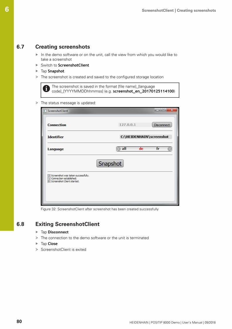
ScreenshotClient | Creating screenshots 6
80 HEIDENHAIN | POSITIP 8000 Demo | User’s Manual | 09/2018
6.7 Creating screenshots
In the demo software or on the unit, call the view from which you would like to
take a screenshot
Switch to ScreenshotClientTap SnapshotThe screenshot is created and saved to the configured storage location
The screenshot is saved in the format [file name]_[language
code]_[YYYYMMDDhhmmss] (e.g. screenshot_en_20170125114100)
The status message is updated:
Figure 32: ScreenshotClient after screenshot has been created successfully
6.8 Exiting ScreenshotClient
Tap Disconnect
The connection to the demo software or the unit is terminated
Tap CloseScreenshotClient is exited

7
HEIDENHAIN | POSITIP 8000 Demo | User’s Manual | 09/2018 81
7 Index
C
Configuration data
Copying the file...................... 49
uploading the file................... 50
Configuring
File name for screenshots..... 78
ScreenshotClient................... 78
Software................................ 48
Storage location for screenshots
78
User interface language of
screenshots........................... 79
D
Demo software
Features................................... 8
Intended use............................ 8
Documentation
Notes on reading..................... 8
Dragging..................................... 20
E
Example
bolt hole circle, row of holes
(programming)....................... 68
bolt hole circle, row of holes
(program run)......................... 72
fit (MDI mode of operation)... 64
Flange drawing...................... 56
Preset (manual operation
mode).............................. 58, 66
rectangular pocket (MDI mode
of operation).......................... 61
through hole (manual operation
mode)..................................... 59
workpiece.............................. 54
Exiting
ScreenshotClient................... 80
F
File management
Menu..................................... 37
G
Gestures
Dragging................................ 20
Holding................................... 19
Operation............................... 19
Tapping.................................. 19
H
Holding....................................... 19
I
Input devices
Operation............................... 18
Installation file
Downloading.......................... 12
L
Language
setting.............................. 25, 51
License key
Activating............................... 48
M
Manual operation....................... 28
menu..................................... 28
Manual operation mode
Example..................... 58, 59, 66
MDI
menu..................................... 30
MDI mode of operation
example........................... 61, 64
Menu
File management................... 37
manual operation................... 28
MDI........................................ 30
programming......................... 34
program run........................... 33
Settings.................................. 39
Switch-off............................... 40
user login............................... 38
Mouse actions
Dragging................................ 20
Holding................................... 19
Operation............................... 19
Tapping.................................. 19
O
OEM bar.................................... 46
operating elements................ 46
Operating elements
add......................................... 22
back....................................... 22
close...................................... 22
confirm................................... 22
drop-down list........................ 21
Main menu............................ 26
OEM bar................................ 46
plus/minus button.................. 21
Screen keyboard.................... 21
slide switch............................ 21
status bar............................... 44
toggle switch......................... 21
undo....................................... 22
Operation
General operation.................. 18
Gestures and mouse actions. 19
Operating elements............... 21
Touchscreen and input
devices................................... 18
P
Password
default password................... 55
Product version.......................... 51
Programming
example................................. 68
menu..................................... 34
program run
example................................. 72
menu..................................... 33
Q
Quick start.................................. 54
S
ScreenshotClient........................ 76
Configuring............................ 78
Connecting............................. 77
Creating screenshots............. 80
Exiting.................................... 80
Information............................ 76
Starting.................................. 77
Screenshots
Configuring the file name....... 78
Configuring the storage
location.................................. 78
Configuring the user interface
language................................ 79
Creating................................. 80
Settings
Menu..................................... 39
Shut-down
Software................................ 24
Software
Activating a license key.......... 48
Configuration data............ 49, 50
Downloading the installation
file.......................................... 12
installation.............................. 13
Shut-down............................. 24
Starting.................................. 23
System requirements............ 12
Uninstallation......................... 15
Starting
ScreenshotClient................... 77
Software................................ 23
Status bar................................... 44
operating elements................ 44
Switch-off
Menu..................................... 40
Symbols and fonts used for
marking text................................. 9
T
Tapping....................................... 19
Tool table
Creating................................. 57
Touchscreen

Index7
82 HEIDENHAIN | POSITIP 8000 Demo | User’s Manual | 09/2018
Operation............................... 18
U
Use
Improper.................................. 8
Intended................................... 8
User
Login...................................... 24
Logout.................................... 24
User login.............................. 24
User interface
After startup........................... 25
File management menu......... 37
Main menu............................ 26
manual operation menu......... 28
MDI menu............................. 30
programming menu............... 34
program run menu................. 33
Settings menu....................... 39
Switch-off menu..................... 40
user login menu..................... 38
User login............................ 24, 38

List of figures 8
HEIDENHAIN | POSITIP 8000 Demo | User’s Manual | 09/2018 83
8 List of figures
Image 1: Installation wizard................................................................................................................. 13
Image 2: Installation wizard with activated demo software option and Screenshot Utility................14
Image 3: User login menu......................................................................................................................23
Image 4: User interface (in Manual operation mode).............................................................................26
Image 5: Manual operation menu in the milling application mode....................................................... 28
Image 6: Manual operation menu in the turning application mode...................................................... 29
Image 7: MDI mode menu in the milling application mode....................................................................30
Image 8: MDI mode menu in the turning application mode...................................................................31
Image 9: MDI block dialog...................................................................................................................... 32
Image 10: Program run menu in the milling application mode............................................................... 33
Image 11: Program run menu in the turning application mode...............................................................34
Image 12: Programming menu in the milling application mode.............................................................. 35
Image 13: Programming menu with simulation window opened............................................................35
Image 14: Programming menu in the turning application mode..............................................................36
Image 15: Programming menu with simulation window opened............................................................36
Image 16: File management menu......................................................................................................... 37
Image 17: User login menu......................................................................................................................38
Image 18: Settings menu......................................................................................................................... 39
Image 19: Settings menu......................................................................................................................... 50
Image 20: Example workpiece..................................................................................................................54
Image 21: Example workpiece– technical drawing...................................................................................56
Image 22: Example workpiece – finding preset D1................................................................................. 58
Image 23: Example workpiece – drilling a through hole.......................................................................... 59
Image 24: Example workpiece – machining a rectangular pocket............................................................61
Image 25: Example workpiece – machining a fit......................................................................................64
Image 26: Example workpiece – finding preset D2................................................................................. 66
Image 27: Example workpiece – programming a bolt hole pattern and a row of holes........................... 68
Image 28: Example workpiece – simulation window............................................................................... 71
Image 29: Example workpiece – drilling a bolt hole pattern and a row of holes...................................... 72
Image 30: ScreenshotClient user interface.............................................................................................. 76
Image 31: ScreenshotClient has been started (not connected yet)......................................................... 77
Image 32: ScreenshotClient after screenshot has been created successfully......................................... 80

DR. JOHANNES HEIDENHAIN GmbHDr.-Johannes-Heidenhain-Straße 583301 Traunreut, Germany +49 8669 31-0 +49 8669 32-5061E-mail: [email protected]
Technical support +49 8669 32-1000Measuring systems +49 8669 31-3104
E-mail: [email protected] support +49 8669 31-3101
E-mail: [email protected] programming +49 8669 31-3103
E-mail: [email protected] programming +49 8669 31-3102
E-mail: [email protected] programming +49 8669 31-3106
E-mail: [email protected]
www.heidenhain.de
Original document
1251620 · 00 · A · 02 · 09/2018 · PDF*I1251620*


