Abstracts of the 31st Southern African Transport Conference (SATC 2012) 9-12 July 2012 Proceedings ISBN Number: 978-1-920017-53-8 Pretoria, South Africa Produced by: Document Transformation Technologies cc Conference organised by: Conference Planners POSSIBLE METHOD OF DETERMINING STRUCTURAL NUMBER FOR FLEXIBLE PAVEMENTS WITH THE FALLING WEIGHT DEFLECTOMETER H Schnoor *and E Horak* *Ndodana Consulting Engineers (Pty) Ltd, Centurion, South Africa Tel: (012) 667 5820; Fax: (012) 667 4682; E-mail: [email protected], [email protected]ABSTRACT The paper describes a procedure where the condition of flexible pavements is investigated with the help of non-destructive tests such as the Falling Weight Deflectometer (FWD). The condition or indication of structural strength is expressed in terms of the Structural Number (SN). An existing method of determining the Structural Number was used as benchmark with data from a recent detailed pavement investigation. The benchmark SN determination also makes use of the Dynamic Cone Penetrometer (DCP) method. Previously only limited aspects of the measured deflection bowl were used to determine SN non-destructively. In this improved procedure additional deflection bowl parameters were investigated for their possible improvement in the determination of the SN or PN. The proposed method was therefore benchmarked against existing methods to determine SN for a pavement to see if it can lead to an improvement in determining SN values. 1. INTRODUCTION The Structural Number (SN) is an index providing an indication of the strength of the pavement layers and of the total pavement structure. This empirical approach is derived by taking the layer material type specific coefficient multiplied by the layer thickness and the sum of these are then the pavement Structural Number (SN). The use of the SN was promoted by the World Bank using this concept in a number of design and performance evaluation and software such as the Highway Development and Management tool (HDM) developed by the World Bank. The HDM IV is the current version of this software and makes use of various forms of the SN in some of the calculations. Recently renewed interest has been shown in South Africa in evaluating existing pavements and their performance by using simplified calculations such as SN versus the more complicated mechanistic analysis methodology. The concept of the Structural Number (SN) was introduced in the 1960s and since then various approaches were based on empirical relations, mechanistic or theoretically based relationships, to determine the SN of pavements. Due to its empirical origin, initially only the maximum deflection was taken into consideration to determine the SN in a non- destructive way if deflection data was available. This approach is ignoring the other portions of the whole deflection bowl reflecting the other pavement layer contributions to structural strength and response. 94
Transcript
Abstracts of the 31st Southern African Transport Conference (SATC 2012) 9-12 July 2012 Proceedings ISBN Number: 978-1-920017-53-8 Pretoria, South Africa Produced by: Document Transformation Technologies cc Conference organised by: Conference Planners
POSSIBLE METHOD OF DETERMINING STRUCTURAL NUMBER FOR FLEXIBLE PAVEMENTS WITH THE FALLING
WEIGHT DEFLECTOMETER
H Schnoor *and E Horak*
*Ndodana Consulting Engineers (Pty) Ltd, Centurion, South Africa Tel: (012) 667 5820; Fax: (012) 667 4682;
ABSTRACT The paper describes a procedure where the condition of flexible pavements is investigated with the help of non-destructive tests such as the Falling Weight Deflectometer (FWD). The condition or indication of structural strength is expressed in terms of the Structural Number (SN). An existing method of determining the Structural Number was used as benchmark with data from a recent detailed pavement investigation. The benchmark SN determination also makes use of the Dynamic Cone Penetrometer (DCP) method. Previously only limited aspects of the measured deflection bowl were used to determine SN non-destructively. In this improved procedure additional deflection bowl parameters were investigated for their possible improvement in the determination of the SN or PN. The proposed method was therefore benchmarked against existing methods to determine SN for a pavement to see if it can lead to an improvement in determining SN values. 1. INTRODUCTION The Structural Number (SN) is an index providing an indication of the strength of the pavement layers and of the total pavement structure. This empirical approach is derived by taking the layer material type specific coefficient multiplied by the layer thickness and the sum of these are then the pavement Structural Number (SN). The use of the SN was promoted by the World Bank using this concept in a number of design and performance evaluation and software such as the Highway Development and Management tool (HDM) developed by the World Bank. The HDM IV is the current version of this software and makes use of various forms of the SN in some of the calculations. Recently renewed interest has been shown in South Africa in evaluating existing pavements and their performance by using simplified calculations such as SN versus the more complicated mechanistic analysis methodology. The concept of the Structural Number (SN) was introduced in the 1960s and since then various approaches were based on empirical relations, mechanistic or theoretically based relationships, to determine the SN of pavements. Due to its empirical origin, initially only the maximum deflection was taken into consideration to determine the SN in a non-destructive way if deflection data was available. This approach is ignoring the other portions of the whole deflection bowl reflecting the other pavement layer contributions to structural strength and response.
94
Abstracts of the 31st Southern African Transport Conference (SATC 2012) 9-12 July 2012 Proceedings ISBN Number: 978-1-920017-53-8 Pretoria, South Africa Produced by: Document Transformation Technologies cc Conference organised by: Conference Planners
It was originally more difficult to record the whole deflection bowl with the old mechanical dial technology associated with the mechanical Benkelman Beam and standard loaded truck manoeuvrings. The deflection points further away from the point of loading generally have a more direct correlation with the structural response of the subgrade and therefore such points were first added to the maximum deflection point to improve the correlations previously developed. Other non-destructive pavement tests were also introduced to improve the incorporation of the whole pavement structure. The use of the Dynamic Cone Penetrometer (DCP) found particular favour as it is also very well calibrated with known bearing capacity indicators such as the California Bearing Ratio (CBR). The DCP provided additional in situ shear strength characteristics in depth of a flexible pavement and increased the confidence or correlation coefficients for the derived SN values for flexible pavements. Significant improvements in non-destructive deflection measuring devices since the 1980s occurred of which the Falling Weight Deflectometer (FWD) was one of the more significant devices accepted by the general road building industry. The FWD makes use of geophones that are placed at certain offsets from its loading plate. The loading plate is loaded in an impulse mode via the dropping or falling of a standard weight through a standard height. The FWD thus simulates a moving wheel load and can accurately measure the whole deflection bowl thus created. This research was done to support the determination of the structural condition or state of flexible pavements via the SN approximation with the help of the FWD. The FWD was chosen because, it is a non-destructive test procedure and it is an easier, less expensive and quicker method compared to the other older empirically based methods of obtaining information about the pavement structural response and associated strength.
2. THE STRUCTURAL NUMBER
The Structural Number (SN), formerly called a "thickness index”, was originally determined with help of the American Association of State Highway Officials (AASHO) road test of the late 1950s and early 1960s. It is used as an indicator to determine the strength of a total pavement structure. In essence, it is the sum of the strengths of all the layers in the pavement. The AASHO road test was the largest road experiment of its time and research outcomes from this study guided pavement design in North America as well as elsewhere in the world. The AASHO road test was performed to investigate the performance of highway pavement structures and how traffic contributed to the deterioration of pavements. The experiment took place on test tracks with known pavement thickness under a moving load of known magnitude and frequency (United States Department of Transportation, 2009). AASHO later changed to American Association of State Highway and Transport Officials (AASHTO). The SN determines the total number of ESALs (Equivalent Single Axle Loads) that a particular pavement can support. The most commonly used equivalent load is 80 kN or 18 kips (Kilo pounds). The performance and deterioration of these test pavements were monitored by accurate material tests, as built records and proper quality control. Non-destructive tests such as the Benkelman beam used an 18 kip axle load to measure
95
Abstracts of the 31st Southern African Transport Conference (SATC 2012) 9-12 July 2012 Proceedings ISBN Number: 978-1-920017-53-8 Pretoria, South Africa Produced by: Document Transformation Technologies cc Conference organised by: Conference Planners
Pavement Component Coefficient
Surface course
Roadmix (low stability) 0.20
Plantmix (high stability) 0.44
Sand asphalt 0.40
Base course
Sand gravel 0.07
Crushed stone 0.14
Cement-treated (no soil-cement)
Compressive strength @ 7 days
650 psi or more 0.23
400 psi to 650 psi 0.20
400 psi or less 0.15
Bituminous-treated
Coarse-graded 0.34
Sand asphalt 0.30
Lime treated 0.15 - 0.30
Subbase course
Sandy gravel 0.11
Sand or sandy clay 0.05 – 0.10
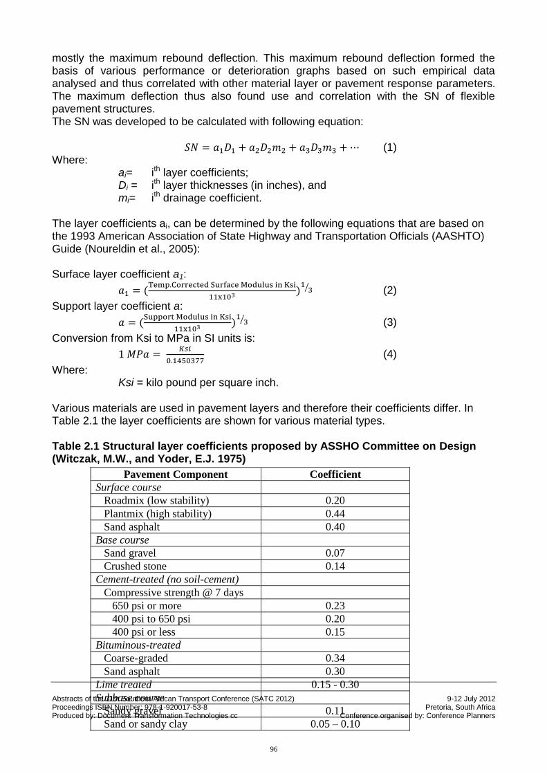
mostly the maximum rebound deflection. This maximum rebound deflection formed the basis of various performance or deterioration graphs based on such empirical data analysed and thus correlated with other material layer or pavement response parameters. The maximum deflection thus also found use and correlation with the SN of flexible pavement structures. The SN was developed to be calculated with following equation:
(1) Where:
ai= ith layer coefficients; Di = ith layer thicknesses (in inches), and mi= ith drainage coefficient.
The layer coefficients ai, can be determined by the following equations that are based on the 1993 American Association of State Highway and Transportation Officials (AASHTO) Guide (Noureldin et al., 2005): Surface layer coefficient a1:
(2)
Support layer coefficient a:
(3)
Conversion from Ksi to MPa in SI units is:
(4)
Where: Ksi = kilo pound per square inch.
Various materials are used in pavement layers and therefore their coefficients differ. In Table 2.1 the layer coefficients are shown for various material types. Table 2.1 Structural layer coefficients proposed by ASSHO Committee on Design (Witczak, M.W., and Yoder, E.J. 1975)
96
Abstracts of the 31st Southern African Transport Conference (SATC 2012) 9-12 July 2012 Proceedings ISBN Number: 978-1-920017-53-8 Pretoria, South Africa Produced by: Document Transformation Technologies cc Conference organised by: Conference Planners
The pavement strength can also be represented by the modified structural number (MSN) or (SNC). It is preferred to use the SNC over the SN as it includes the effect of the subgrade. In South Africa the term SNC is used. It is termed SNC, because the CBR (Californian Bearing Ratio) of the subgrade is taken into account. The SNC can be calculated by the following equation (Rohde et al., 1998):
(5) Where:
SN = Structural number;
SNSG= Subgrade structural number, determined by the following equation (Hodges, et al., 1975, as referred to by Rohde et al., 1998), and
(6). Where: CBR = California Bearing Ratio of the subgrade in per cent. Even with the old Benkelman beam rebound deflections there was recognition that the available information can be improved or better used to determine the SN values of flexible pavements more accurately. A multitude of non-destructive deflection measuring devices have developed since the 1960s and since the 1980s devices such as the falling Weight Deflectometer (FWD) has found favour with road researchers and practitioners due to its ease of use and ability to measure the whole deflection bowl. As previously stated the use of SN values found favour with World Bank pavement performance and evaluation software such as HDM IV. In the late 1990s considerable work was done to improve the correlations with non-destructive measuring methodologies to determine the SN values of flexible pavements. Seven approaches were identified (Rohde, 1995) to determine the pavement structural number through non-destructive testing (NDT). The summary of their formulae and approaches are summarised in Table 2.2 to follow. Most of them either use the Dynamic Cone Penetrometer (DCP) or the Falling Weight Deflectometer (FWD). Two hundred and forty in-service pavements in Africa and South East Asia were used in this significant study to verify and evaluate the different methods to determine SN values for flexible pavement structures (Rohde, 1995). The use of the FWD deflection bowl was however initially still largely restricted to the use of the maximum deflection and one other point further away from the point of loading. As Rhode showed only a few made use of more points on the deflection bowl. This improved use of the FWD deflection bowl clearly improved the correlation of total pavement response.
97
Abstracts of the 31st Southern African Transport Conference (SATC 2012) 9-12 July 2012 Proceedings ISBN Number: 978-1-920017-53-8 Pretoria, South Africa Produced by: Document Transformation Technologies cc Conference organised by: Conference Planners
Table 2.2 Summary of methods using non-destructive measurements to determine SN
Where: ag = layer coefficient of standard materials (AASHO road test), Ei= layer resilient modulus Eg = resilient modulus of standard materials (AASHO road test), hi = layer thickness in inches The Modified Structural Number (SNC) can now be calculated by the equation (5).
The back-calculations are done with the help of two programs, Modulus and Elmod
2. DCP Analysis Method DN > 2mm per blow (8)
DN ≤ 2mm per blow (9) Where:
DN = penetration rate of DCP in mm per blow The layer coefficients are determined with the following equations: (for Base Course) (10)
(for Subbase Course) (11)
This method involves the analysis of DCP results of each pavement layer. The CBR is determined by the relationships developed by Kleyn and Savage (1982)
3. AASHTO Method II
The subgrade modulus is:
(12)
Where: P = the dynamic load of the FWD in pounds µ = the subgrade Poisson’s ratio dr = the measured deflection at a distance rd from the load plate centre in inches rd = the radial distance from plate centre to point measurement in inches
The structural number formula as defined in the AASHTO guide was modified with the following relationship:
(13)
Where:
The method involves only surface deflections that are normalized at a FWD plate load of 566 kPa. The subgrade modulus is determined with equation with the peak
deflections and layer thicknesses.
98
Abstracts of the 31st Southern African Transport Conference (SATC 2012) 9-12 July 2012 Proceedings ISBN Number: 978-1-920017-53-8 Pretoria, South Africa Produced by: Document Transformation Technologies cc Conference organised by: Conference Planners
D0 = the peak FWD deflection in inches HP = the pavement layer thickness in inches Ir = the load radius in inches Esg = the subgrade modulus in pound per square inch
4. Jameson’s Formulae
(14)
(15) Where: D0 = the peak deflection at 700 kPa D900= the deflection 900 mm from the centre of the loading plate at 700kPa in microns D1500= the deflection 1500 mm from the centre of the loading plate 700kPa in microns The SNC can now be calculated with equation (5).
The structural number and subgrade CBR are determined from surface FWD deflections
5. Howard’s Formulae
At a structural number of 2.5 and greater:
(16)
If SN< 2.5, the SN is given by:
(17)
Where: HP = the total pavement layer thickness in mm The subgrade modulus Esg is determined by the following equation:
(18)
The subgrade modulus is then translated to CBR with equation (15) and the SNC can be determined with equation (5)
The structural number is determined by measured pavement thickness and deflections normalized at 700 kPa contact pressure
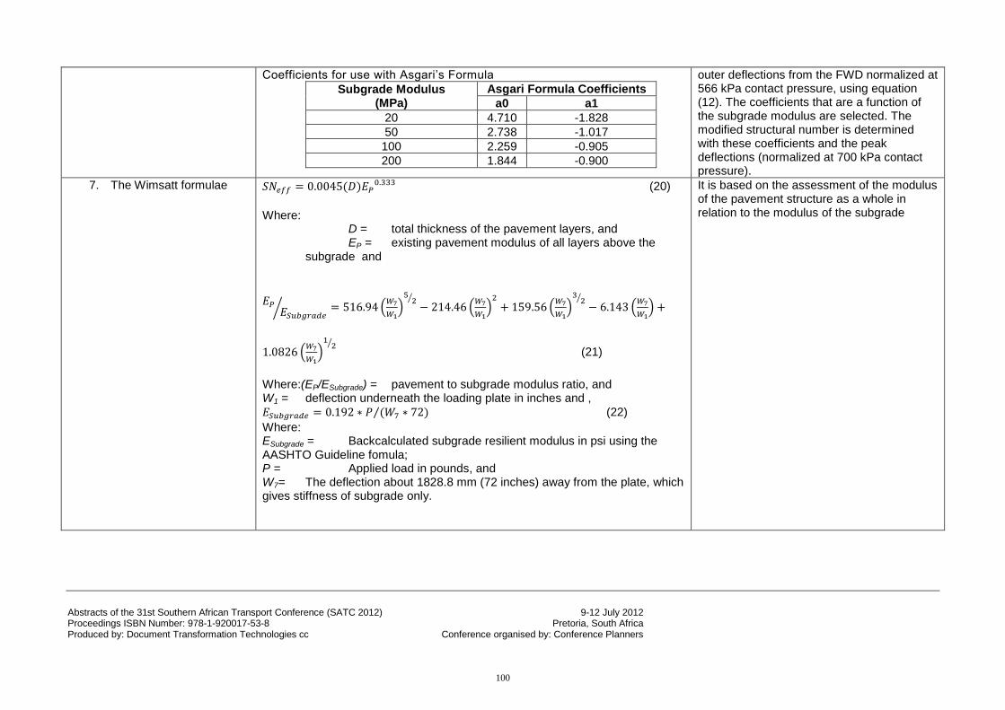
6. Asgari’s Formulae
(19)
The subgrade modulus is determined from
99
Abstracts of the 31st Southern African Transport Conference (SATC 2012) 9-12 July 2012 Proceedings ISBN Number: 978-1-920017-53-8 Pretoria, South Africa Produced by: Document Transformation Technologies cc Conference organised by: Conference Planners
Coefficients for use with Asgari’s Formula
Subgrade Modulus (MPa)
Asgari Formula Coefficients
a0 a1
20 4.710 -1.828
50 2.738 -1.017
100 2.259 -0.905
200 1.844 -0.900
outer deflections from the FWD normalized at 566 kPa contact pressure, using equation (12). The coefficients that are a function of the subgrade modulus are selected. The modified structural number is determined with these coefficients and the peak deflections (normalized at 700 kPa contact pressure).
7. The Wimsatt formulae (20)
Where:
D = total thickness of the pavement layers, and EP = existing pavement modulus of all layers above the
subgrade and
(21)
Where:(EP/ESubgrade) = pavement to subgrade modulus ratio, and W1 = deflection underneath the loading plate in inches and ,
(22)
Where: ESubgrade = Backcalculated subgrade resilient modulus in psi using the AASHTO Guideline fomula; P = Applied load in pounds, and W7= The deflection about 1828.8 mm (72 inches) away from the plate, which gives stiffness of subgrade only.
It is based on the assessment of the modulus of the pavement structure as a whole in relation to the modulus of the subgrade
100
Abstracts of the 31st Southern African Transport Conference (SATC 2012) 9-12 July 2012 Proceedings ISBN Number: 978-1-920017-53-8 Pretoria, South Africa Produced by: Document Transformation Technologies cc Conference organised by: Conference Planners
Rohde (1995) subsequently developed his relationships using more information from the deflection bowl. The peak deflection under the FWD plate is measuring not only the elastic compression of the pavement layers, but also the deflection in the subgrade. This is not favourable, as the modulus of the pavement structure should be determined separately to quantify their structural contribution. The Irwin rule or “two-third” rule is thus applied (Zhang, Z et al., 2003) which states that 95 per cent of the deflections measured at the surface initiate below a line deviating 34 degrees from the horizontal (as illustrated in Figure 2.1). With this simplification, Rhode (Zhang, Z et al., 2003) realized that the surface deflection of an offset measured at 1.5 times the pavement thickness result entirely due to the pavement subgrade response.
Figure 2.1 The Stress Distribution and Measured Deflection Bowl beneath the FWD Load (Zhang, Z et al., 2003) Deflections are normalized at 566 kPa contact pressure and are at two offsets:
1.5 x nominal pavement thickness, and
1.5 x nominal pavement thickness + 450 mm are determined by an interpolation method.
101
Abstracts of the 31st Southern African Transport Conference (SATC 2012) 9-12 July 2012 Proceedings ISBN Number: 978-1-920017-53-8 Pretoria, South Africa Produced by: Document Transformation Technologies cc Conference organised by: Conference Planners
The parameters Structural Index of the Pavement (SIP) and the Structural Index of the Subgrade (SIS) can be determined by the following two equations: (23)
(24) Where: D0 = peak deflection measured under a standard 40 kN FWD load;
D1.5Hp = surface deflection measured at offset of 1.5 times Hp under a standard 40 kN FWD load;
D1.5HP+450= the deflection in microns measured at an offset 1.5 times HP + 450 mm under a 40 kN FWD load, and
HP = total pavement thickness.
The structural number and subgrade modulus can be calculated with the following equations:
(25)
(26)
In Table 2.3 and 2.4 the coefficients for SN - SIP relationships and coefficients for Esg – SIS relationship are given. Table 2.3 Coefficients for SN-SIP Relationship (Rhode, 1995)
Table 2.4 Coefficients for Esg – SIS Relationship (Rhode, 1995)
Total Pavement Thickness
a3 a4 a5
HP ≤ 380 mm 9.138 -1.236 -1.903
380 mm , HP ≤ 525 mm 8.756 -1.213 -1.780
525 mm , HP 10.655 -1.254 -2.453
An analysis has been done by Rohde (1995) to determine which method would be the best. The result of the analysis was that the following two approaches should be used:
Jameson’s Formulae (If only FWD data is available), and
Rohde’s Relationships (If FWD data and total pavement thickness are available).
It should be noted that Wimsatt’s methods was not included in this comparison (See Table 2.2).
3. THE USE OF STANDARD DEFLECTION BOWL PARAMETERS
Various deflection bowl parameters have been used by various researchers (Horak, 2009) describing various portions of the deflection bowl and various correlations and methodologies have thus been developed to make better use of the whole deflection bowl
Surface type a0 a1 a2
Surface seals 0.1165 -0.3248 0.8241
Asphalt concrete 0.4728 -0.4810 0.7581
102
Abstracts of the 31st Southern African Transport Conference (SATC 2012) 9-12 July 2012 Proceedings ISBN Number: 978-1-920017-53-8 Pretoria, South Africa Produced by: Document Transformation Technologies cc Conference organised by: Conference Planners
in structural analyses. In Table 3.1 to follow a summary of the various deflection bowl parameters and their correlations are shown. In South Africa the use of BLI, MLI and LLI have found favour in semi-empirical analyses or benchmark methodologies as it tends to describe the structural response of the pavement structure better. This approach developed by Horak (2009) makes it possible to get a much more comprehensive understanding of the structural condition of the pavement and is in essence a further refinement of the Irwin’s “two-thirds” or 34 degrees load spreading rule. The Base Layer Index (BLI) correlates with the positive curvature and structural response of the base layer and surfacing. The Middle Layer Index (MLI) correlates with the inflection zone and therefore the structural response of the subbase layers in general and the Lower Layer Index (LLI) with the negative curvature on the outer regions of the measured deflection bowl and therefore the subgrade and selected layers of the pavement structure. Nevertheless, there are other deflection bowl parameters as listed in Table 3.1, which shows that there are other deflection bowl parameters which describe the total pavement structure response probably more accurately. All of these parameters were tested for improved SN determination with the possibility of simplifying the calculations from only known deflection bowl parameters without further knowledge needed regarding total pavement thickness or layer thicknesses as still required in the Rhode formulae. Table 3.1 Deflection bowl parameters (Horak et. al 2009)
Parameter Formula Reference
original Structural indicator
1. Maximum deflection
D0 as measured Shrivner, 1968
Gives an indication of all structural layers with about 70% contribution by the subgrade
2. Radius of Curvature (RoC)
Where L=127 mm in the Dehlen curvature meter and 200 mm for the FWD
Dehlen, 1962
Gives an indication of the structural condition of the surfacing and base condition
3. Base Layer Index (BLI) also known as Surface Curvature Index (SCI)
Shrivner, 1968 Gives an indication of primarily the base layer structural condition
4. Middle Layer Index (MLI) also known as Base Damage Index (BDI)
Petersen, 1972
Gives an indication of the subbase and probably selected layer structural condition
5. Lower Layer Index (LLI) ) also known as Base Curvature Index (BCI)
Petersen, 1972
Gives an indication of the lower structural layers like the selected and the subgrade layers
6.Spreadability, S
Vaswani, 1971
Supposed to reflect the structural response of the whole pavement structure, but with weak correlations
7. Area, A
Hill and Thompson, 1989
The same as above
8. Shape factors
Hoffman and Thompson, 1982
The F2 shape factor seemed to give better correlations with subgrade moduli while F1 gave weak correlations
9. Slope of Deflection
Vaswani, 1971 Weak correlations observed
103
Abstracts of the 31st Southern African Transport Conference (SATC 2012) 9-12 July 2012 Proceedings ISBN Number: 978-1-920017-53-8 Pretoria, South Africa Produced by: Document Transformation Technologies cc Conference organised by: Conference Planners
10. Additional shape factor
Xu, et al. (2001) Lower layer condition or depth to a stiff layer
11. Area under pavement profile
Hill and Thompson, 1989
Characterizing condition of the pavement upper layers
12. Additional areas
Xu, et al. (2001) Condition of middle layer Condition of lower layers
13. Area indices
Xu, et a.l (2001)
Condition of upper layer
Condition of middle layer
Condition of middle layer
Condition of lower layer
4. DATA ANALYSIS
In order to illustrate the potential to use such standardised deflection bowl parameters in the calculation of SN of a pavement with only the measured deflection bowl and definition of the pavement type as flexible, the data set from a detailed investigation of a recent rehabilitation investigation was used. The data of the detailed investigation on the N1-22 and N1-23 included numerous test pit profiling, field tests and a very data rich FWD survey (done at 50 m intervals). A considerable number of laboratory tests were used in this analysis to provide very reliable material and pavement response descriptions.
The SN was thus determined with the method of Rohde, . With the method of Rohde the SN was determined at the test pits with the actual layer thickness and CBRs known. Such test pit information and surrounding deflection measurements were therefore used with considerable confidence that the SN determined for such an area or section in close proximity to the test pit. With this SN thus determined, correlation studies were done with various pavement deflection bowl parameters to determine which provides the best correlations by using only deflection bowl measurements in close proximity to the test pits or representative of the previously defined uniform sections linked to a specific test pit information. Of all these deflection bowl parameters, it was shown that the use of the BLI, MLI, LLI and the Area under pavement profile (AUPP) would be of most interest, as there was a clear relationship between them and the calculated SN. This is illustrated in Figure 4.1 to Figure 4.4. The graphs of the remaining parameters did not show a clear relationship. These data showed a power relationship. By plotting a power trend line through the points, the R2 values where above 0.9, except for the LLI versus SN graph which has a R2 of 0.79. These data was then further analysed by stepwise regression analysis.
104
Abstracts of the 31st Southern African Transport Conference (SATC 2012) 9-12 July 2012 Proceedings ISBN Number: 978-1-920017-53-8 Pretoria, South Africa Produced by: Document Transformation Technologies cc Conference organised by: Conference Planners
5. STEPWISE REGRESSION ANALYSIS
The stepwise regression was done with the regression analysis tool in Microsoft Excel 2007. The data has a power relationship and the regression analysis can only analyse data that has a linear relationship. Therefore, the natural logarithm of the data was taken. The plot of the natural logarithm of the deflection bowl parameter versus the plot of the natural logarithm of SN was shown to have linear relationship. In Figure 5.1 the linearization of AUPP is illustrated.
Figure 4.1 Area under pavement profile versus SN
Figure 4.2 BLI versus SN
Figure 4.3 Middle Layer Index versus SN Figure 4.4 Lower Layer Index versus SN
105
Abstracts of the 31st Southern African Transport Conference (SATC 2012) 9-12 July 2012 Proceedings ISBN Number: 978-1-920017-53-8 Pretoria, South Africa Produced by: Document Transformation Technologies cc Conference organised by: Conference Planners
Figure 5.1 Linearization of AUPP versus linearization of SN
In the stepwise regression analysis the following linearization of the deflection bowl parameters were used; lnAUPP, lnLLI, lnBLI and lnMLI. The typical result of the fifth and final regression is shown in Table 5.1. Table 5.1 Final stepwise regression analysis output
R² = 0.985
0.00
0.50
1.00
1.50
2.00
2.50
3.00
3.50
3.00 4.00 5.00 6.00 7.00 8.00
ln S
NlnAUPP
lnAUPP versus lnSN
106
Abstracts of the 31st Southern African Transport Conference (SATC 2012) 9-12 July 2012 Proceedings ISBN Number: 978-1-920017-53-8 Pretoria, South Africa Produced by: Document Transformation Technologies cc Conference organised by: Conference Planners
With the stepwise regression analysis done, it was concluded that using two parameters AUPP and BLI would make most sense. The following relationship was determined with the analysis.
(27) Converting the equation by using the log rules of linear algebra the following equation was determined.
(28)
This equation was then used to calculate the SN and was then compared to the Structural Number that was determined at the test pits and to the SN determined by the method of Rohde. As AUPP and BLI increase the SN generally decreases. This makes sense, because when the BLI and AUPP increase it shows that the stiffness of the pavement decreases and with that the SN should decrease. The Structural number was determined by the method of G Rohde (equation 25) and the Structural Number column 4 with the determined equation 28. In Table 5.2 to follow a typical result from such a comparative study is shown. Table 5.2 The Structural Number at a test pit
The SN determined by the improved relationship was generally higher than the one determined by the method of Rohde. It needs to be noted in the determination of the Structural Number according to the layers of the test pits, the SNSG sometimes worked out as being negative and shows a possible problem in the equation. This was the case when the material class was of a lesser quality than G9 in the TRH14 classification system.
6. CONCLUSION AND RECOMMENDATIONS
6.1 Conclusion
The SN is a concept to determine the structural strength of a pavement. The literature study showed that there are eight methods of determining the SN. By definition the SN reflects the contribution of each pavement layer. However, these methods tend to lump the pavement structure together and to evaluate or calculate the subgrade contribution separately.
107
Abstracts of the 31st Southern African Transport Conference (SATC 2012) 9-12 July 2012 Proceedings ISBN Number: 978-1-920017-53-8 Pretoria, South Africa Produced by: Document Transformation Technologies cc Conference organised by: Conference Planners
In this research project it was endeavoured to evaluate the structural contribution of all pavement structural layers by using mostly non-destructive survey methodology, the FWD without any further pavement layer or material information. It was shown that the pavement structural condition can be represented by various deflection parameters. Data from the N1-22 and N1-23 were used to calculate the SN based on actual material and layer thicknesses. The existing method by Rohde was calibrated and an improved relationship was determined. FWD data was used to illustrate that deflection bowl parameters BLI, MLI, LLI and AUPP can improve the calculation of the SN. This is an improvement versus other methods (Rohde etc.). The data used, was from an asphalt base pavement and can only be applied to these pavements. It falls out of the reach of this research project to investigate the behaviour of cemented and granular base pavements.
6.2 Recommendation
As the analysis was done only from data of an asphalt base pavement, it cannot be said if this method will also apply to other pavements. This should be investigated and further research should be done on cemented base and granular base pavements.
7. ACKNOWLEDGEMENT AND DISCLAIMER
This pilot study was done by Mr H Schnoor as part of his final year research project under the guidance of Prof Wynand Steyn and co-leadership of Dr Horak. It is thus focussed on proof of ability to correctly apply research methodology and the ability to do individual research. The study is therefore only at a pilot study investigation level. The use of the detailed investigation data from the N1-22 and 23 is acknowledged and is owned by Bakwena Toll Operator. The use of the data is thankfully acknowledged and it is stated clearly that the views expressed and conclusions drawn here are that of the authors and not that of the owners of the data or any of the consultants involved in any aspect of any investigation on these road sections.
8. REFERENCE LIST
Chastain, W.E. and Schwartz, D.R. 1964. AASHO Road Test equations applied to the design of bituminous pavements in Illinois. Highway Research Record 90, Highway Research Board, Washington D.C.
Emery, S.J. 1985. Prediction of Moisture Content for use in Pavement Design. Ph.D. dissertation. University of the Witwatersrand, Johannesburg, South Africa.
Horak, E. 1988. Aspects of Deflection Basin Parameters used in Mechanistic Rehabilitation Design Procedure for Flexible Pavements in South Africa. PhD thesis, Department of Civil Engineering at the University of Pretoria, Pretoria, South Africa.
Horak, E. 2008. Benchmarking the Structural condition of flexible pavements with deflection bowl parameters. Journal of the South African Institute of Civil Engineering, Vol. 50, No 2, June, pp 2-9.
108
Abstracts of the 31st Southern African Transport Conference (SATC 2012) 9-12 July 2012 Proceedings ISBN Number: 978-1-920017-53-8 Pretoria, South Africa Produced by: Document Transformation Technologies cc Conference organised by: Conference Planners
Horak, E. and Emery, S. 2006. Evaluation of airport pavements with FWD deflection bowl parameter benchmarking methodology.
Horak, E., Maina, J.W., van Wijk, I., Hefer, A., Jordaan, G., Olivier, P., de Bruin, P.W. 2009. Revision of the South African Pavement Design Method. Draft Contract Report SANRAL/SAPDM/B-2/2009-01.
Ioannides, A.M. 1991. Theoretical Implications of the AASHTO 1986 Non-destructive Testing Method 2 for Pavement Evaluation. In Transportation Research Record 1307, TRB, National Research Council, Washington, D.C., p. 211-220.
Jooste, F. and Long F. 2007.A Knowledge Based Structural Design Method for Pavements Incorporating Bituminous Stabilized Materials, Draft for Review.
Kleyn, E. G., and Savage, P. E. 1982. The Application of the Pavement DCP to Determine the Bearing Properties and Performance of the Road Pavements, International Symposium on Bearing Capacity of Roads and Airfields, Trodheim, Norway.
NDLI. 1995. Modelling Road Deterioration and Maintenance Effects in HDM-4. Final Report Asian Development Bank Project RETA 5549. ND Lea International Ltd. Vancouver. p. 397.
Noureldin, S., Harris, D., Zhu, K., Li, S. 2005. Non-Destructive Estimation of Pavement Thickness, Structural Number and Subgrade Resilience along Indiana Department of Transportation Highways. Purdue University.
Paterson, W. D. O. 1987. Road Deterioration and Maintenance Effects: Models for Planning and Management. A World Bank Publication. The Johns Hopkins University Press. Baltimore. 1987. 454 p.
Pienaar, P.A., Visser, A.T. and Dlamini, L. 2000. A comparison of the HDM-4 with the HDM-III on a case study in Swaziland. South African Transport Conference. South Africa
Rohde G.T., 1995. Modelling Road Deterioration and maintenance effects in HDM-4, Chapter 12, Pavement Strength in HDM-4 with FWDs.
Rohde, G. T., 1994. Determining Pavement Structural Number from FWD Testing, TRR 1448, Transportation Research Board, Washington DC.
Rohde, G.T., Jooste, F., Sadzik, E., and Henning, T. 1998. The Calibration and use of HDM-IV Performance Models in a Pavement Management System. Fourth International Conference on Managing Pavements. Durban, South Africa.
United States Department of Transportation. 2009. ASSHO Road Test. Website. http://www.fhwa.dot.gov/infrastructure/50aasho.cfm. 30th March 2010.
Witczak, M.W., and Yoder, E.J. 1975. Principles of pavement design. 2nd ed. John Wiley & Sons, Inc. United States of America
Zhang, Z., Claros, G., Manuel, L. and Damnjanovic, I., 2003. Evaluation of the pavement structural condition at network level using Falling Weight Deflectometer (FWD) data. 82nd Annual Meeting of the Transportation Research Board and Publication in the Transportation Research Record Series. Washington, DC, United States of America.