77
Post-acceleration of RIBs – Important consideration and challenges Arup Bandyopadhyay VECC Indo-Japan School on Advance Accelerators for Ions and Electrons IUAC, New Delhi, Feb 16-18, 2015

Post-acceleration of RIBs – Important
consideration and challenges
Arup BandyopadhyayVECC
Indo-Japan School on Advance Accelerators for Ions and Electrons
IUAC, New Delhi, Feb 16-18, 2015

Accelerator-based research in nuclear physics, material science, isotope production, radiochemistry, analytical chemistry etc., & development of large scale detectors and experimental facilities
Accelerator design, development, construction, and operation
Our Main Activities
Theoretical nuclear physics
Collaborations at RHIC, LHC, INO, FAIR, TRIUMF, Fermi Lab, 6
Regional Radiation Medicine Centre

224cm Variable Energy Cyclotron; Operating since 1977

VECC SUPERCONDUCTING CYCLOTRON
Kbend=520
Accelerate heavy ion beams
Energy 80 MeV/nucleon for light ions
8 MeV/nucleaon for heavy ions
Radio-frequency system Radio-frequency system 9-27 MHz
80 kV maximum Dee voltage
Superconducting magnet Average magnetic field = 5 Tesla
100 Tonnes magnet iron
12.5 Tonnes cryostat

Indo-FAIR Collaboration
SC dipole magnets
SC quad/multipolemagnets
Beam stoppersMuCH : CBM expts.
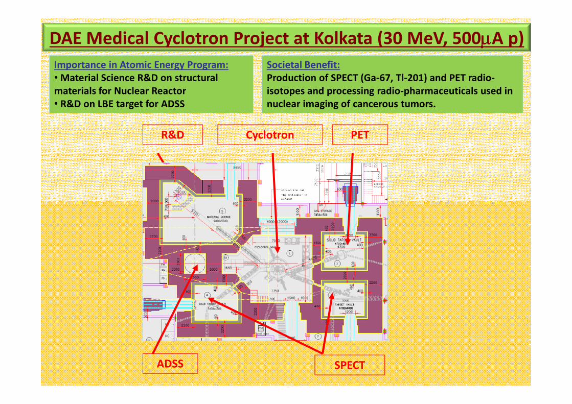
DAE Medical Cyclotron Project at Kolkata (30 MeV, 500µµµµA p)
Societal Benefit:
Production of SPECT (Ga-67, Tl-201) and PET radio-
isotopes and processing radio-pharmaceuticals used in
nuclear imaging of cancerous tumors.
Importance in Atomic Energy Program:
•Material Science R&D on structural
materials for Nuclear Reactor
• R&D on LBE target for ADSS
Cyclotron PETR&D
SPECTADSS

Ions of β-unstable nuclei
What is RIB ??
Pro
ton
Nu
mb
er
Neutron Number
Pro
ton
Nu
mb
er
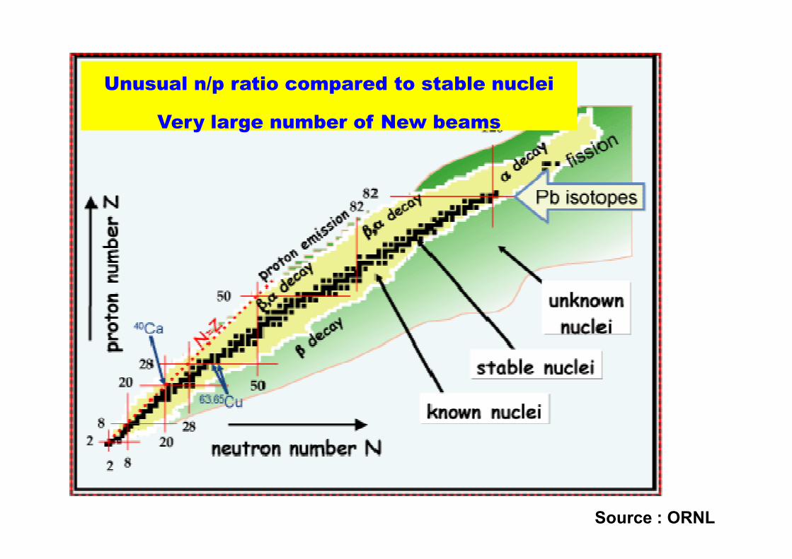
Unusual n/p ratio compared to stable nuclei
Very large number of New beams
Source : ORNL
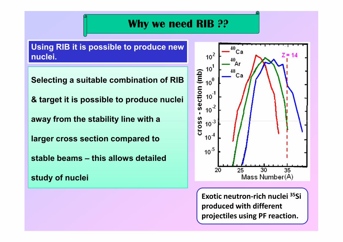
Why we need RIB ??
Using RIB it is possible to produce new nuclei.
Selecting a suitable combination of RIB
& target it is possible to produce nuclei
away from the stability line with a away from the stability line with a
larger cross section compared to
stable beams – this allows detailed
study of nuclei
Exotic neutron-rich nuclei 35Si
produced with different
projectiles using PF reaction.

Nuclear Halo
11Be11Li
208Pb
fmr
ArR
2.10
31
0=
∗=
Pb
Magic Numbers : 2, 8, 20, 28, 50, 82, 126
Double magic nuclei : 4He, 16O, 40Ca, 48Ca, 48Ni, 56Ni, 208Pb
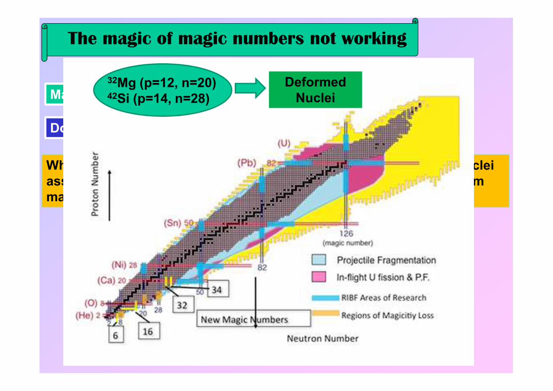
The magic of magic numbers not working
When proton or neutron shells are filled with magic numbers, the nuclei assume spherical shapes and when the p or n numbers are away from magic numbers, the nucleus is deformed
32Mg (p=12, n=20)42Si (p=14, n=28)
Deformed Nuclei
magic numbers, the nucleus is deformed

Ion Beam
Collimators Detector
Sample
Ion Beam Channeling
Study of formation & propagation of lattice defects by “Emission
Challening” Technique.
Physics Motivation Material Science
Detector
Detector Sample
e-, e+, α
Emission Channeling
Req. implantation dose of radioactive atoms is significantly lower than that of ion channeling experiment.
Radiation damage during channeling analysis negligible.
Sensitivity of EC >> higher than ion channeling tech. (1E13 & 1E18 /cc)

Medical research
Radioisotope Therapy : A radionuclide is delivered to a
tumor site using a biologically active molecule which
decays via β- or α.
Using RIB one can produce such nuclide with high specific
activity as it will be carrier free or no-carrier-added form
(suitable target+projectile & clean separation) + availability
of new radioisotopes.
Physics Motivation
PET (Positron Emission Tomography) – medical imaging of
tumors, mapping of human brain and heart function. Most
of the PET isotopes are short lived for clinical use &
research. Using RIB it is possible to produce longer lived
PET isotopes (72As : T1/2~ 26 hours) which are carrier free
i.e. high sp. Activity.

Production of RIBs
Ion Source
Mass / Isobaric separation
Primary Beam (n, p, αααα, 3He,
HI’s)Thick Target
Projectile
Fragment
Primary Beam (HI: E >300 MeV/u)
PROJECTILE FRAGMENTOR
Post-Accelerator
(cyclotron / RFQ+Linac)
Mass / Isobaric separation
RIBs
Fragment
Separator
ISOL POST-ACCELERATOR
Storage
Ring Secondary
Target
Storage
Ring Secondary
Target

Production of RIBs
Ion Source
Mass / Isobaric separation
Primary Beam (n, p, αααα, 3He,
HI’s)Thick Target
Thick Target Sustain high current for
longer duration / Fast & efficient release
properties.
Ion Source High on-line efficiency for higher charge states for many elements in
hostile environment of target.
Separation & Acceleration Isobaric
separation and acceleration without sacrifycing
the intensity.
Post-Accelerator
(cyclotron / RFQ+Linac)
Mass / Isobaric separation
RIBs
ISOL POST-ACCELERATOR
Storage
Ring Secondary
Target
the intensity.
Pros :Pros :Pros :Pros :
• Beam Quality Clean beam / Small
energy width.
Cons :Cons :Cons :Cons :
• HalfHalfHalfHalf----life life life life Lower threshold.

Production of RIBs
Projectile
Fragment
Primary Beam (HI: E >300 MeV/u) Primary Beam IS High current
for high charge states.
Pri. Beam acceleration Acceleration of HIs to high energy (≈
300 MeV/u) W/O losing intensity.
Separation Clean separation of
PFs.
PROJECTILE FRAGMENTOR
Fragment
Separator
Storage
Ring Secondary
Target
Pros :Pros :Pros :Pros :
• HalfHalfHalfHalf----life life life life Even isomeric beams can
be produced.
• Exoticity Extremely exotic species
can be produced.
Cons :Cons :Cons :Cons :
Beam Quality Mixed beam /
Larger energy width.
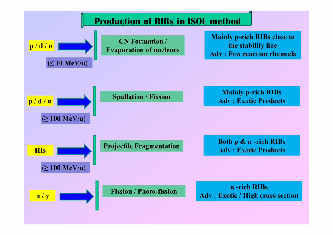
p / d / α
(≤ 10 MeV/u)
CN Formation /
Evaporation of nucleons
Mainly p-rich RIBs close to
the stability line
Adv : Few reaction channels
p / d / α
(≥ 100 MeV/u)
Spallation / FissionMainly p-rich RIBs
Adv : Exotic Products
Production of RIBs in ISOL method
(≥ 100 MeV/u)
HIs
(≥ 100 MeV/u)
Projectile FragmentationBoth p & n -rich RIBs
Adv : Exotic Products
n / γFission / Photo-fission
n -rich RIBs
Adv : Exotic / High cross-section

Production of RIBs in ISOL method
2/2310~2/1~
1310~1
4321
=
∗∗∗∗∗∗=
µ
εεεεσ
cmnucleicmgTARGET
N
ppsAPRII
TARGETN
PRII
RIBI
)14321
(1010~
22610~50~
=∗∗∗
−
εεεε
σ
ppsRIBI
cmmb
RIB release & Transport Ion Source Decay Loss Acceleration
It is important to maximise all the efficiency factors involved

Cyclone 30
LouvainLouvainLouvainLouvain----la la la la NeuveNeuveNeuveNeuve ---- BelgiumBelgiumBelgiumBelgium
30 MeV 500 µA p
Thick Target
ECR IS 6.4 GHz
Cyclone 110
0.65 – 5 MeV /uηTr : 3-6%
Cyclone 44
0.2-0.8 MeV /uηTr : 25%

GANIL GANIL GANIL GANIL ---- FranceFranceFranceFrance
CSS-1
K=380
CSS-2
K=380
Ion Source &C01 / C02
K=30
K=380
Heavy Ion Stable
Beam : 95 MeV/u
CIME
K=265RIB Production Target & Ion
Source (6.4GHz ECR)
Radioactive Ion Beam :
<25 MeV/u

SPIRALSPIRALSPIRALSPIRAL----II GANIL II GANIL II GANIL II GANIL ---- FranceFranceFranceFrance
RFQ 1 & 288 MHz
QWR @ 88 MHz 12 QWR, β=0.07
HWR @ 176 MHz 18 HWR, β=0.14
33 MeV p
40 MeV d @ 5mA
14.5 MeV/u HI @1mA
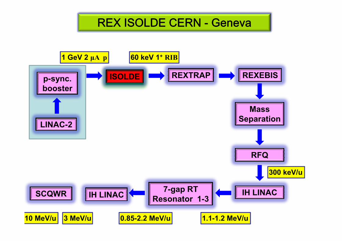
REX ISOLDE CERN REX ISOLDE CERN REX ISOLDE CERN REX ISOLDE CERN ---- GenevaGenevaGenevaGeneva
ISOLDE REXTRAP REXEBIS
LINAC-2
p-sync. booster
1 GeV 2 µA p 60 keV 1+ RIB
Mass Separation
LINAC-2Separation
RFQ
IH LINAC
300 keV/u
7-gap RT Resonator 1-3
1.1-1.2 MeV/u0.85-2.2 MeV/u
IH LINAC
3 MeV/u
SCQWR
10 MeV/u

ISAC TRIUMF ISAC TRIUMF ISAC TRIUMF ISAC TRIUMF ---- CanadaCanadaCanadaCanada
Cyclotron
500 MeV 100 µA p
Thick Target
Ionisation & Separation RFQ
153 keV/u
IH LINAC
1.53 MeV/u
QWR @ 106 MHz 8 QWR, β=0.057
QWR @ 106 MHz 12 QWR, β=0.071
QWR @ 141.4 MHz 20 QWR, β=0.11
6.5 MeV/u
e-LINAC @ 1.3 GHz 50MeV 10mA CW
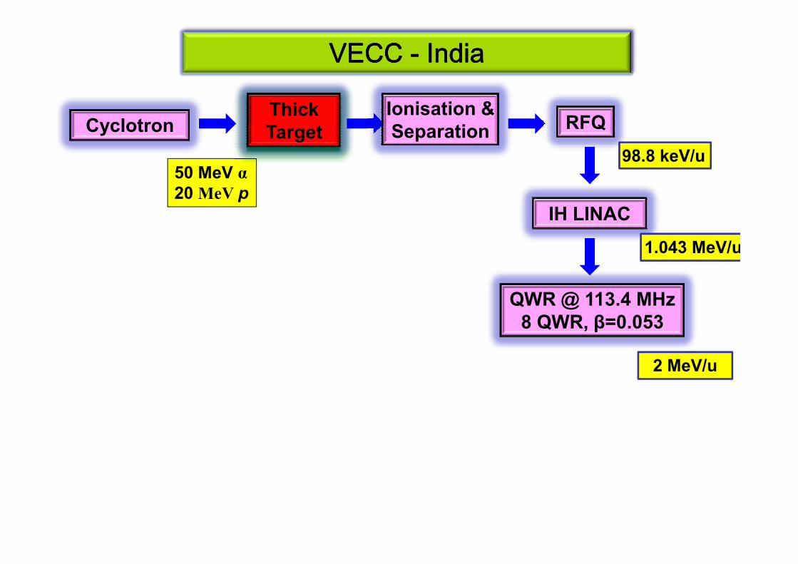
VECC VECC VECC VECC ---- IndiaIndiaIndiaIndia
Cyclotron
50 MeV α20 MeV p
Thick Target
Ionisation & Separation RFQ
98.8 keV/u
IH LINAC
1.043 MeV/u
QWR @ 113.4 MHz 8 QWR, β=0.053
2 MeV/u

VECC ANURIB VECC ANURIB VECC ANURIB VECC ANURIB ---- IndiaIndiaIndiaIndia
Cyclotron
50 MeV 1mA p
Thick Target Ionisation
RFQe-LINAC Target
Separation
IonisationRFQ
100 keV/u
IH LINAC
1 MeV/u
QWR
7 MeV/u
e-LINAC
50 MeV
2mA e-
Target Ionisation
PFS Cyclotron
100 MeV/u

PostPostPostPost----acceleration Schemesacceleration Schemesacceleration Schemesacceleration Schemes
Facility Post-accelerator
RIB Energy (MeV/u)
Post-accln. Eff. (%)
Louvain-la Neuve Cyclone 110 0.65-5 3-6
Louvain-la Neuve Cyclone 44 0.2-0.8 25
SPIRAL CIME (K=265) 25 (9 for Fission Fr)
REX ISOLDE RFQ + IH
LINAC + 7-gap
resonator +
0.85-3 (10) > 95%
resonator +
QWR
ISAC TRIUMF RFQ + IH
LINAC + QWR
0.153-6.5 MeV/u >95%
RIBF VECC RFQ + IH
LINAC + QWR
0.1-2 MeV/u >85%
RFQ+IH LINAC+QWR is a better option from efficiency pointof view – involves many RF systems and their synchroni-sation, cost and floor space

Synchronous PhaseSynchronous PhaseSynchronous PhaseSynchronous Phase
Egap
tgap
Q O
P
R
0˚ -90˚ 90˚
Q : The synchronous ion
P (R) : An ion which reaches the
gap centre at an earlier (later) time
compared to the sync. Ion – say at
time t0-∆t (t0+∆t)
P experiences less field and R more compared to Q : So, ∆t will more compared to Q : So, ∆t will
be less for both P & R in next gap
This is true for phases between -
90˚ and 0˚ because RF field is increasing with time : longitudinal
focusing.
For -90˚<Φs<90˚ there will be ion acceleration
For -90˚<Φs<0˚ there will be longitudinal focusing during the accelerationand for 0˚<Φs<90˚ there will be longitudinal defocusing

RF defocusingRF defocusingRF defocusingRF defocusing
+ -
Egap R For negative synchronous phase
For the +ve RF
cycle :
Ions
tgap
Q O
P
R
0˚ -90˚ 90˚
(-90˚<Φs<0˚), the RF field in the gap
increases with time when the ion
bunch crosses the gap
This implies radial outward force at
the exit of the gap will be stronger
than radial inward force at the
entrance of the gap : Net defocusing

Energy Gain across a gapEnergy Gain across a gapEnergy Gain across a gapEnergy Gain across a gapIf the field across the gap is DC i.e. No time
dependance and having the value equal to the field at
the time the ion is at the gap centre then energy gain
by the ion of charge ‘q’ can be expressed as :
When one considers the sinusoidal variation of the RF field then :
Φ∗∗=∗Φ∗∗=∆ cos0
)cos0
( VqLEqw L
Φ∗∗∗=∆ cos0
TVqw
Where ‘T’ is called transit time factor which depends on the field distribution
across the gap and can be written as :
∫−
=
∫−
==
2/
2/),0(
2/
2/)(cos),0(
L
LdzzrE
L
LdzzwtzrE
T

Choice of Synchronous Phase for Ion AccelerationChoice of Synchronous Phase for Ion AccelerationChoice of Synchronous Phase for Ion AccelerationChoice of Synchronous Phase for Ion Acceleration
Egap
tgap
Q O
P
R
0˚ -90˚ 90˚
Synchronous phase (-90˚<Φs<0˚):
There will be longitudinal focusing /bunching of the beam
There will be acceleration of thebeam given by
Φ∗∗∗=∆ cos0
TVqw
There will be RF defocusing to be
taken care of by other options
0
Synchronous phase Φs~0˚ :
Maximum Acceleration and minimum RF defocusing
No longitudinal focusing / bunching : to be taken care of by other options
Better beam quality

Shunt ImpedanceShunt ImpedanceShunt ImpedanceShunt Impedance
Shunt impedance (Z) is the figure of merit of an accelerating structure in
producing accelerating field per unit power loss within the structure and can
be written as :
Lwall
PzEZ
2
=
Lwall
∫=L
dzzELzE0
1 Is the average value of the Z component of the RF field and
the integral to be taken over the entire structure length or an
integral number of RF cell lengths. Pwall is the power loss
within the RF structure over a length L.

Radio Frequency Quadrupole (RFQ)Radio Frequency Quadrupole (RFQ)Radio Frequency Quadrupole (RFQ)Radio Frequency Quadrupole (RFQ)
It is an accelerating structure which can provide radial focusing duringthe acceleration and also works as an excellent buncher. For heavy ionsthis is the preferred structure from a few keV/u to few hundreds of keV/u.
For Low β : magnetic focusing not that effective + little room for placing magnets
p/D RFQ Structure : Vane Type Heavy Ion RFQ : Rode type
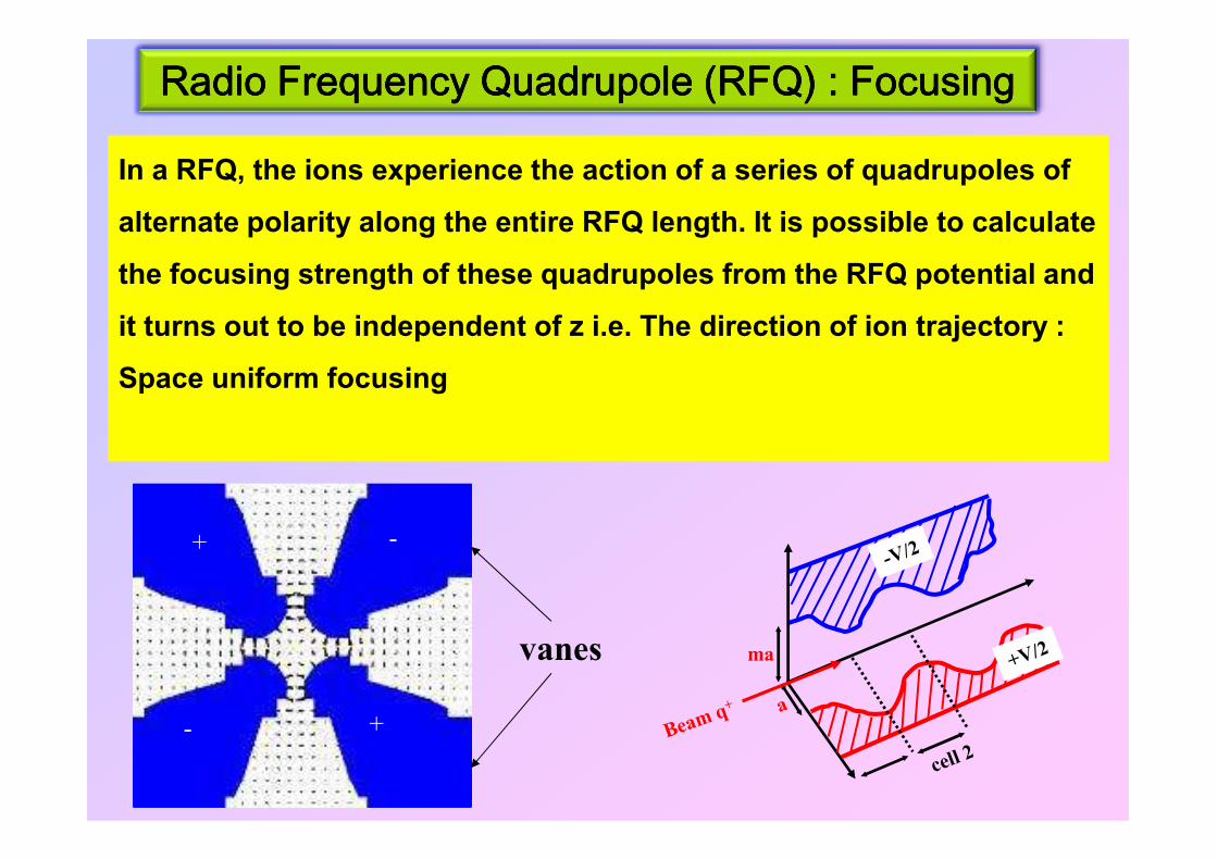
Radio Frequency Quadrupole (RFQ) : FocusingRadio Frequency Quadrupole (RFQ) : FocusingRadio Frequency Quadrupole (RFQ) : FocusingRadio Frequency Quadrupole (RFQ) : Focusing
SN
NS
In a RFQ, the ions experience the action of a series of quadrupoles of
alternate polarity along the entire RFQ length. It is possible to calculate
the focusing strength of these quadrupoles from the RFQ potential and
it turns out to be independent of z i.e. The direction of ion trajectory :
Space uniform focusing
+
+
-
-
vanes

Radio Frequency Quadrupole (RFQ) : AccelerationRadio Frequency Quadrupole (RFQ) : AccelerationRadio Frequency Quadrupole (RFQ) : AccelerationRadio Frequency Quadrupole (RFQ) : Acceleration
2*a2*m*a
βλ/2 βλ/2
A*V0
Opposite
Vanes
RF Pot.
on axis
Due to vane/rod modulation, there
is a component of RF field along
the direction of the ion motion
which accelerates the ions
If there is acceleration in the first
cell, there will be deceleration in
the second. However, the cell
length is such that by the time the
ions reach the second cell the RF
phase changes by 180˚ i.e.
Acceleration throughout.

Radio Frequency Quadrupole (RFQ) : PotentialRadio Frequency Quadrupole (RFQ) : PotentialRadio Frequency Quadrupole (RFQ) : PotentialRadio Frequency Quadrupole (RFQ) : Potential
2*a2*m*a
βλ/2 βλ/2
A*V0
Opposite
Vanes
RF Pot.
on axis
The electric potential among the vanes in the lowest order is expressed as :
( )
+=
kzkrAI
arXV
zrU
cos0
2cos2
20),,(
θθ
1212 −− mm
( ) ( ) 1212
002
12
+−≈
+−=
m
m
mkaIkaIm
mA
( )12
20
1+
≈−=m
kaAIX
a: Characteristic radiusA : Acceleration parameterm : Modulation parameterX: Focusing parameter

Radio Frequency Quadrupole (RFQ) : Cell parametersRadio Frequency Quadrupole (RFQ) : Cell parametersRadio Frequency Quadrupole (RFQ) : Cell parametersRadio Frequency Quadrupole (RFQ) : Cell parameters
Radial Matching section : The transverse acceptance of a RF system is timeRadial Matching section : The transverse acceptance of a RF system is time
dependent – the radial matching section makes the time dependent transverseacceptance of the RFQ time independent at its input
Shaping section : In this section the synchronous phase is slowly changedfrom -90˚ to -88˚ (say) to transform the DC beam to a bunched beam
Gentle buncher : In this section the beam is bunched by changing the
synchronous phase rapidly from -88˚ to -60˚ (say) without changing theallowed longitudinal phase space (separatrix) area
Acceleration setion : The sync. Phase is changed to its final desired value of -30˚ say and thereafter is is kept contant.

Radio Frequency Quadrupole (RFQ) : Cell parametersRadio Frequency Quadrupole (RFQ) : Cell parametersRadio Frequency Quadrupole (RFQ) : Cell parametersRadio Frequency Quadrupole (RFQ) : Cell parameters

Radio Frequency Quadrupole (RFQ) : Beam dynamicsRadio Frequency Quadrupole (RFQ) : Beam dynamicsRadio Frequency Quadrupole (RFQ) : Beam dynamicsRadio Frequency Quadrupole (RFQ) : Beam dynamics

rf cell -2rf cell -1
Radio Frequency Quadrupole (RFQ) : PostsRadio Frequency Quadrupole (RFQ) : PostsRadio Frequency Quadrupole (RFQ) : PostsRadio Frequency Quadrupole (RFQ) : PostsVanes
Post
4-wire transmission-line
with open circuit termination
2-wire transmission-line
with short circuit termination
≡≡
≡
+
+
--
Lp Cv Rp
vpCL
fπ21
=
pR
VP
2
2
=
sv
pRC
R22
1
ω≅
pRQ∝
lossenergy
storedenergyQ =
Deflection of vanes !!!

Radio Frequency Quadrupole (RFQ) : RF simulationRadio Frequency Quadrupole (RFQ) : RF simulationRadio Frequency Quadrupole (RFQ) : RF simulationRadio Frequency Quadrupole (RFQ) : RF simulation

Radio Frequency Quadrupole (RFQ) : RF simulationRadio Frequency Quadrupole (RFQ) : RF simulationRadio Frequency Quadrupole (RFQ) : RF simulationRadio Frequency Quadrupole (RFQ) : RF simulation

Radio Frequency Quadrupole (RFQ) : RF simulationRadio Frequency Quadrupole (RFQ) : RF simulationRadio Frequency Quadrupole (RFQ) : RF simulationRadio Frequency Quadrupole (RFQ) : RF simulation
f = 35.18 MHz
• Q = 9830
• Rp = 87.1 kΩΩΩΩ
• Power loss = 14.5 kW
Power loss distribution
cavity = 0.62 kW
• vane = 6.0 kW
• post + base plate = 7.87 kW
Power loss distribution

Radio Frequency Quadrupole (RFQ) : Thermal Radio Frequency Quadrupole (RFQ) : Thermal Radio Frequency Quadrupole (RFQ) : Thermal Radio Frequency Quadrupole (RFQ) : Thermal ManagementManagementManagementManagement
Convective heat loss due to LCW water thru the cooling system

Radio Frequency Quadrupole (RFQ) : Thermal Radio Frequency Quadrupole (RFQ) : Thermal Radio Frequency Quadrupole (RFQ) : Thermal Radio Frequency Quadrupole (RFQ) : Thermal ManagementManagementManagementManagement
Temperature distribution in RFQ structure

Vane profile from PARMTEQ⇓⇓⇓⇓
3D modeling of profile
⇓⇓⇓⇓
Radio Frequency Quadrupole (RFQ) : MachiningRadio Frequency Quadrupole (RFQ) : MachiningRadio Frequency Quadrupole (RFQ) : MachiningRadio Frequency Quadrupole (RFQ) : Machining
4545
⇓⇓⇓⇓X,Y,Z co-ordinates of ball-end mill cutter
⇓⇓⇓⇓Optimum tool path generation
⇓⇓⇓⇓Machining of vane
⇓⇓⇓⇓Check co-ordinates (CMM) & surface finish (Talysurf)
20 µµµµm ~ 2 µµµµmSample vane
requirement∆∆∆∆/r0≤≤≤≤0.5%∆∼∆∼∆∼∆∼30µµµµmδ∼δ∼δ∼δ∼11µµµµm

MACHINING OF MODULATED VANE – CMERI , DURGAPUR
Cubical Spline interpolation
Machined vane in assembled condition

Frequency : 33.7 MHzFrequency : 33.7 MHzFrequency : 33.7 MHzFrequency : 33.7 MHz q/A ≥ 1/16q/A ≥ 1/16q/A ≥ 1/16q/A ≥ 1/16
Energy : 1.38 Energy : 1.38 Energy : 1.38 Energy : 1.38 29 keV/u 29 keV/u 29 keV/u 29 keV/u
Vane Length : 1.552 mVane Length : 1.552 mVane Length : 1.552 mVane Length : 1.552 m
1.7m Long RFQ1.7m Long RFQ1.7m Long RFQ1.7m Long RFQ
Max. modulation : 1.935Max. modulation : 1.935Max. modulation : 1.935Max. modulation : 1.935
Vane Voltage : Vane Voltage : Vane Voltage : Vane Voltage : ±±±± 45.9 kV 45.9 kV 45.9 kV 45.9 kV
Focusing strength : 4.83Focusing strength : 4.83Focusing strength : 4.83Focusing strength : 4.83
Characteristic radius rCharacteristic radius rCharacteristic radius rCharacteristic radius r0000: 7.1 mm : 7.1 mm : 7.1 mm : 7.1 mm
RRRRpppp: 174 k: 174 k: 174 k: 174 kΩΩΩΩQ: 9830Q: 9830Q: 9830Q: 9830
Commissioned in 2005Commissioned in 2005Commissioned in 2005Commissioned in 2005

Frequency : 37.8 MHzFrequency : 37.8 MHzFrequency : 37.8 MHzFrequency : 37.8 MHz q/A ≥ 1/14q/A ≥ 1/14q/A ≥ 1/14q/A ≥ 1/14
Energy : 1.73 Energy : 1.73 Energy : 1.73 Energy : 1.73 98.8 keV/u 98.8 keV/u 98.8 keV/u 98.8 keV/u
No. of gaps : 9No. of gaps : 9No. of gaps : 9No. of gaps : 9 Vane Length : 3.12 mVane Length : 3.12 mVane Length : 3.12 mVane Length : 3.12 m
3.4m Long RFQ3.4m Long RFQ3.4m Long RFQ3.4m Long RFQ
Vane Voltage : Vane Voltage : Vane Voltage : Vane Voltage : ±±±± 53.7 kV 53.7 kV 53.7 kV 53.7 kV φφφφssss : : : : ----21.521.521.521.5°°°°
AcclnAcclnAcclnAccln. grad. : 2.13 MV/m . grad. : 2.13 MV/m . grad. : 2.13 MV/m . grad. : 2.13 MV/m RRRRpppp: 65 k: 65 k: 65 k: 65 kΩΩΩΩ
Q: 8026Q: 8026Q: 8026Q: 8026
Commissioned in 2008Commissioned in 2008Commissioned in 2008Commissioned in 2008
RFQ RFQ RFQ RFQ –––– Difficulties & LimitationsDifficulties & LimitationsDifficulties & LimitationsDifficulties & Limitations
• Critical machining requirement
• Very demanding alignment tolerance of the vanes
• Critical cooling requirement
• Low shunt impedance and acceleration gradient as part of power is
used for providing transverse focusingused for providing transverse focusing
So, one switches over to other linear accelerators as soonas it becomes practically feasible.

Drift Tube LINAC (DTL)
DT Stem
Drift Tube Post coupler
• Uses TM mode for acceleration
• Stems are mechanical support
• Post couplers to shift freq. of competing
modes.
• Cell length βλ E in all gaps are in phase (0-
mode structure)
• Mainly used for the acceln. of p & HI for • Mainly used for the acceln. of p & HI for
5%<β<40%
BEAM

Interdigital H LINAC (IH)
• Uses TE mode for acceleration
•Cell length βλ/2 E in adjacent gaps are in opposite phase (π – mode structure).
• High Z compared to DTL for β < 10%.
• Much smaller transverse dimension (1/3rd) compared to DTL
• Mainly used for the acceln. Of HI for 10%<β. Z ~ 1/β2
BEAM
+V
-VE


Finding the Correct Operating Field
Freq.
[MHz]
E_Kil.
MV/m
E_Kil.*1.3
MV/m
E_Kil.*1.4
MV/m
37.8 8.1 10.5 11.3
75.6 10.3 13.4 14.4
β1λ/2 β2λ/2 β3λ/2 β4λ/2
BEAM

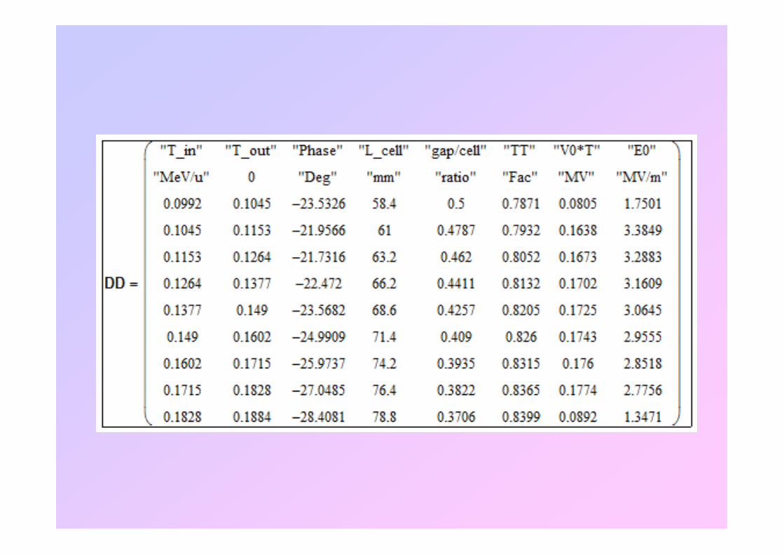
Finding the Correct Operating Field
6 104×
0.50 0.47 0.44 0.41
6
2-D elctrostatic field for various gap to cell length ratios have been
calculated – for intermediate gap to cell length ratios the fields have been
interpolated – these fields have been used for the generation of cell
geometry.
1− 0.5− 0 0.5 10
2 104×
4 104×
0.41 0.39 0.37 0.354
2
0
E[A
rb. U
nit
]
-1 -0.5 0 0.5 1

Energy Gain across a gapEnergy Gain across a gapEnergy Gain across a gapEnergy Gain across a gap
If the field across the gap is DC i.e. No timedependance and having the value equal to the field at
the time the ion is at the gap centre then energy gain
by the ion of charge ‘q’ can be expressed as :
When one considers the sinusoidal variation of the RF field then :
Φ∗∗=∗Φ∗∗=∆ cos0
)cos0
( VqLEqw L
Φ∗∗∗=∆ cos0
TVqw
Where ‘T’ is called transit time factor which depends on the field distribution
across the gap and can be written as :
∫−
=
∫−
==
2/
2/),0(
2/
2/)(cos),0(
L
LdzzrE
L
LdzzwtzrE
T

Drift Tubes
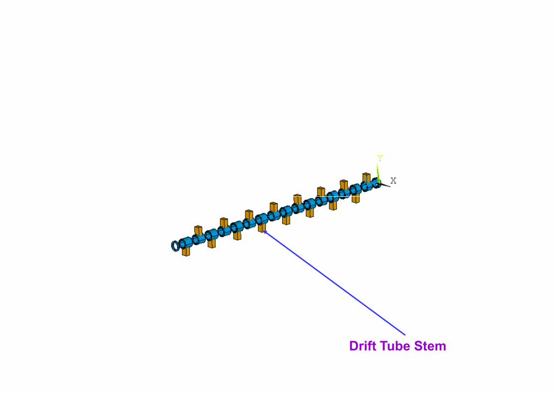
Drift Tube Stem
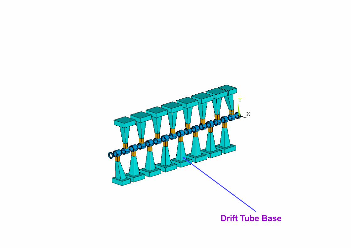
Drift Tube Base

Upper Ridge
Lower Ridge

CAVITYf & Z
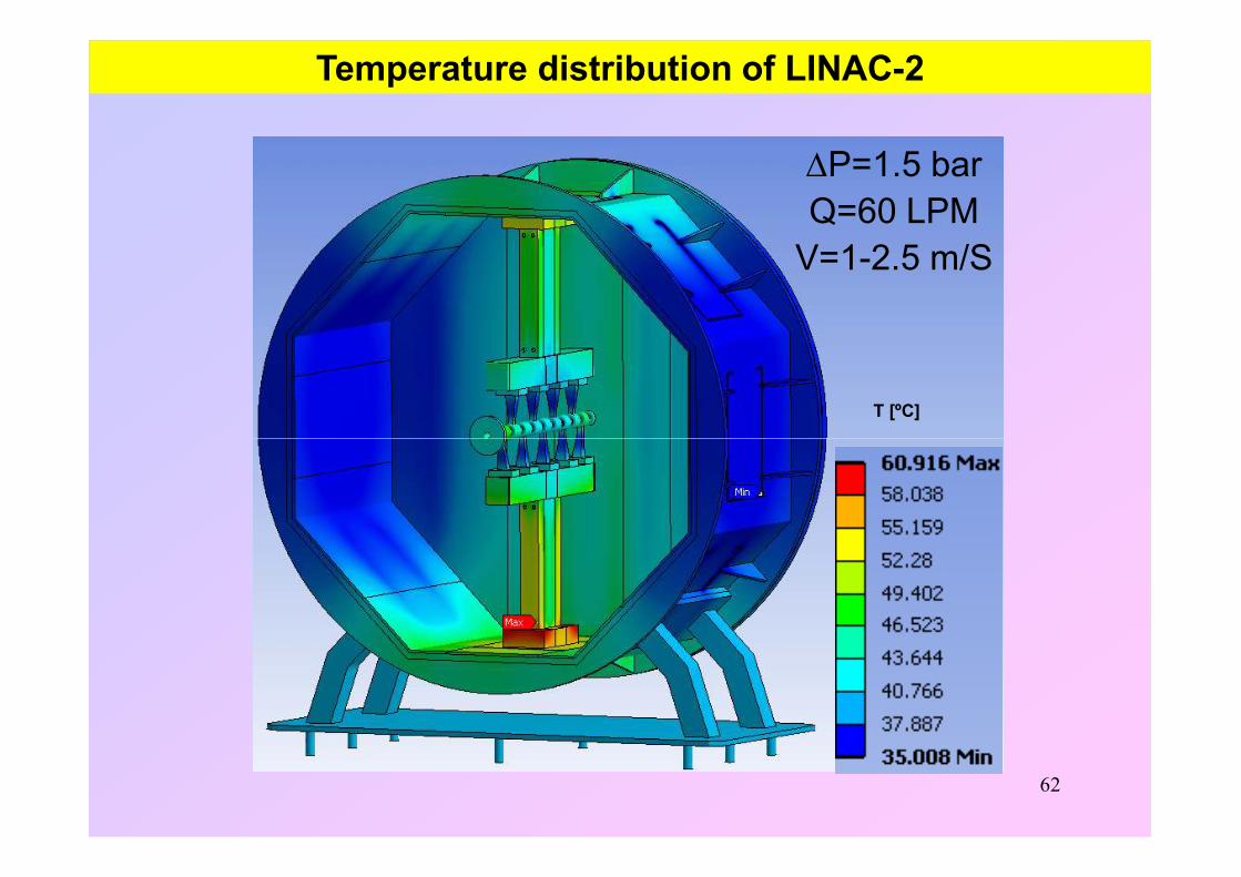
Temperature distribution of LINAC-2
T [ºC]
∆P=1.5 barQ=60 LPM
V=1-2.5 m/S
62

Vertical deformation of LINAC-2
• Loads : Atm. Press. , Self weight , Thermal
Upper DT
End DT
63
Deformation [mm]
Lower
DT

Axial deformation of LINAC-2
• Loads : Atm. Press. , Self weight , Thermal
64
Deformation [mm]

Frequency : 37.8 MHzFrequency : 37.8 MHzFrequency : 37.8 MHzFrequency : 37.8 MHz q/A ≥ 1/14q/A ≥ 1/14q/A ≥ 1/14q/A ≥ 1/14
Energy : 98.8 Energy : 98.8 Energy : 98.8 Energy : 98.8 186.2 186.2 186.2 186.2 keVkeVkeVkeV/u /u /u /u
IH cavity IH cavity IH cavity IH cavity ---- 1111Frequency : 37.8 MHzFrequency : 37.8 MHzFrequency : 37.8 MHzFrequency : 37.8 MHz q/A ≥ 1/14q/A ≥ 1/14q/A ≥ 1/14q/A ≥ 1/14
Energy : 186.2 Energy : 186.2 Energy : 186.2 Energy : 186.2 289.1 289.1 289.1 289.1 keVkeVkeVkeV/u /u /u /u
IH cavity IH cavity IH cavity IH cavity ---- 2222
NIMNIMNIMNIM----A560(2006)182A560(2006)182A560(2006)182A560(2006)182

Frequency : Frequency : Frequency : Frequency : 37.8 37.8 37.8 37.8 MHzMHzMHzMHz q/A ≥ q/A ≥ q/A ≥ q/A ≥ 1/141/141/141/14
Energy : Energy : Energy : Energy : 289.1289.1289.1289.1 289.1 keV/u 289.1 keV/u 289.1 keV/u 289.1 keV/u
RebuncherRebuncherRebuncherRebuncher –––– 2 & 32 & 32 & 32 & 3Frequency : 75.6 MHzFrequency : 75.6 MHzFrequency : 75.6 MHzFrequency : 75.6 MHz q/A ≥ 1/14q/A ≥ 1/14q/A ≥ 1/14q/A ≥ 1/14
Energy : 289.1 Energy : 289.1 Energy : 289.1 Energy : 289.1 413.9 413.9 413.9 413.9 keVkeVkeVkeV/u /u /u /u
IH cavity IH cavity IH cavity IH cavity ---- 3333

All these accelerators are operated as and when required
Transmitters developed by SAMEER, Mumbai
Measured Tr. Efficiency :
RFQ ~ 90%
RFQ-LINAC1-LINAC2 ~ 66%
RFQ-LINAC1-LINAC2-LINAC3 ~ 50%

Frequency : 75.6 MHzFrequency : 75.6 MHzFrequency : 75.6 MHzFrequency : 75.6 MHz q/A ≥ 1/7q/A ≥ 1/7q/A ≥ 1/7q/A ≥ 1/7
Energy : 413.9 Energy : 413.9 Energy : 413.9 Energy : 413.9 717.8 717.8 717.8 717.8 keVkeVkeVkeV/u /u /u /u
IH cavity IH cavity IH cavity IH cavity ---- 4444
Frequency : 75.6 MHzFrequency : 75.6 MHzFrequency : 75.6 MHzFrequency : 75.6 MHz q/A ≥ 1/7q/A ≥ 1/7q/A ≥ 1/7q/A ≥ 1/7
Energy : Energy : Energy : Energy : 777717.8 17.8 17.8 17.8 1043 keV/u 1043 keV/u 1043 keV/u 1043 keV/u
IH cavity IH cavity IH cavity IH cavity ---- 5555

Activity Commissioning
nnnn++++ ECR sourceECR sourceECR sourceECR source 20022002200220021.7m Long RFQ1.7m Long RFQ1.7m Long RFQ1.7m Long RFQ 20052005200520053.4m Long RFQ3.4m Long RFQ3.4m Long RFQ3.4m Long RFQ 2008200820082008IH LINAC cavity IH LINAC cavity IH LINAC cavity IH LINAC cavity ---- 1111 2009200920092009IH LINAC cavity IH LINAC cavity IH LINAC cavity IH LINAC cavity ---- 2222 2010201020102010IH LINAC cavity IH LINAC cavity IH LINAC cavity IH LINAC cavity ---- 2222 2010201020102010IH LINAC cavity IH LINAC cavity IH LINAC cavity IH LINAC cavity ---- 3333 2011201120112011----12121212First acceleration of RIBFirst acceleration of RIBFirst acceleration of RIBFirst acceleration of RIB 2012201220122012IH LINAC cavity IH LINAC cavity IH LINAC cavity IH LINAC cavity ---- 4444 20132013201320131111++++ ECR source ECR source ECR source ECR source ---- only PMsonly PMsonly PMsonly PMs 2013201320132013RebuncherRebuncherRebuncherRebuncher 2 & 32 & 32 & 32 & 3 2014201420142014IH LINAC cavity IH LINAC cavity IH LINAC cavity IH LINAC cavity ---- 5555 March 2015March 2015March 2015March 2015

Gas-jet
≈
Skimmer
RIB
Reaction products
ECR ion-source
He
RVCF catcher
beam
Transportcapillary
p,ααααRadioactive
recoils
15m
1 atm
10-4 mbar 10-5 mbar
Production & Acceleration of RIBsProduction & Acceleration of RIBsProduction & Acceleration of RIBsProduction & Acceleration of RIBs
Radioactive atoms from Rootspump
products (aerosols)
Injection chamber
plasma
targets
He+ cyclohexane
Target chamberRIB site
ECRECR
RFQ2RFQ2
L2L2 L1L1L3L3
Radioactive atoms from
target chamber in vault
HR cave RIB site
Det-FC3Det-FC3
Det-FC2Det-FC2 Det – FC1Det – FC1
DetectorDetector

List of RIBs Produced
RIB Prod. route T1/2 PPS at FC1 PPS at
FC2
42K 40Ar(α,pn) 12.36 hr 3.1 x 10⁴ 2.7 x 10³
43K 40Ar(α,p) 22.3 hr 2.0 x 10⁴ 1.2 x 10³
41Ar 40Ar(α,2pn) 109 min 4.6 x 10³ 1.3 x 10³
NIMNIMNIMNIM----B317(2013)227B317(2013)227B317(2013)227B317(2013)227NIMNIMNIMNIM----B317(2013)227B317(2013)227B317(2013)227B317(2013)227RSIRSIRSIRSI----84(2013)03330184(2013)03330184(2013)03330184(2013)033301
Production & Acceleration of RIBsProduction & Acceleration of RIBsProduction & Acceleration of RIBsProduction & Acceleration of RIBs
Ar Ar(α,2pn) 109 min 4.6 x 10 1.3 x 10
14O 14N(p, n) 71 s 6.7 x 10⁴ 5.0 x 10³
RIB Prod. route
Primary beam energy (MeV)
T1/2 pps @ ECR exit (FC1)
pps @ before RFQ (FC2)
pps @ after RFQ (FC3)
14O 14N(p, n) 11 71 s 6.7 x 10⁴ 5.0 x 10³ 3.2 x 10³
Acceleration of 14O through RFQ to 1.4 MeV

IH-3
RB-3
RB-4
72K130 Vault
Target Ion Source
ECRIS

Advanced National Facility for Unstable and Rare Isotope Beams (ANURIB)Advanced National Facility for Unstable and Rare Isotope Beams (ANURIB)

eeee----LINAC for producing nLINAC for producing nLINAC for producing nLINAC for producing n----rich RIBs rich RIBs rich RIBs rich RIBs
Cyclotron for producing pCyclotron for producing pCyclotron for producing pCyclotron for producing p----rich RIBs rich RIBs rich RIBs rich RIBs
Both ISOL & PFS type RIB facility Both ISOL & PFS type RIB facility Both ISOL & PFS type RIB facility Both ISOL & PFS type RIB facility
Both RIB & stable isotope beamsBoth RIB & stable isotope beamsBoth RIB & stable isotope beamsBoth RIB & stable isotope beams
Fragmentation of RIBs for producing near dripFragmentation of RIBs for producing near dripFragmentation of RIBs for producing near dripFragmentation of RIBs for producing near drip----line nucleiline nucleiline nucleiline nuclei

Acknowledgement :
• RIKEN Accelerator Research Facility (RARF), Japan
• TRIUMF, Vancouver, Canada
• CMERI, Durgapur, India
• SAMEER, Mumbai, India• SAMEER, Mumbai, India
• SAMEER Centre for Electromagnetics, Chennai, India
•
•
•

76

Charge Stripping
"Elelment"
"F"
"F"
"Ne"
"Ar"
"K"
"Ga"
"As"
"Ga"
"Ge"
"As"
"Se"
"At. No."
9
9
10
18
19
31
33
31
32
33
34
"Mass #"
17
18
19
35
38
64
70
78
80
83
85
"q-after-stripping"
6
6
6
9
10
14
14
14
14
14
15
"Charge fraction"
44
44
40
33
33.4
21.8
22.3
21.8
22.3
22.4
21.8
"(q/A)_new"
0.353
0.333
0.316
0.257
0.263
0.219
0.2
0.179
0.175
0.169
0.176
q/A=1/7=0.143
RIB_new
"Se"
"Br"
"Kr"
"Rb"
"Ag"
"In"
"I"
"Xe"
"Cs"
"Ba"
"La"
"Ce"
"Pr"
"Nd"
34
35
36
37
47
49
53
54
55
56
57
58
59
60
85
88
90
93
118
123
133
135
138
140
143
145
148
150
15
15
15
16
20
21
22
21
22
22
22
22
22
22
21.8
22.9
23.3
22.5
22.1
21.1
18.9
18
17.1
16.7
16.5
16
16.2
16.4
0.176
0.17
0.167
0.172
0.169
0.171
0.165
0.156
0.159
0.157
0.154
0.152
0.149
0.147
=
16 18 20 22 24 260
5
10
15
20
Charge Fraction after stripping
Charge State
f n( )
n


