16
9BSST POWER AMPLIFIER OWNER’S MANUAL UPDATED 2007-01-08

9BSSTPOWER AMPLIFIEROWNER’S MANUAL
UPDATED 2007-01-08

9BSST FIVE CHANNEL POWER AMPLIFIER
Table of Contents
General Introduction Page1 InstalationandVentilation
Rear Panel Input Settings/Connections Page2 SettingInputSelectorSwitch BalanceInputConnectorConfiguration SettingPolarity SettingInputSensitivity Output Binding Posts and Polarity Page3
Front Panel Description Page4 LEDIndicators(Power-upSequence) LEDIndicators(OperatingConditions)
Power Control Panel Page5 MasterCurcuit-Breaker ACPowerInput Local/AutoSwitch Local/ExternalSwitch
Rack Mounting Instructions Page6 IndividualModuleRemoval ChannelFuseType/Location
5.1 Typical Home Theatre Setup Page7
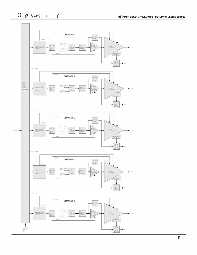
Block Diagram of the 9BSST Page8
Typical Performance Graphs Page9-10
Bridging Channels Page11
External Dimensions Page12
Technical Specifications Page13
Important Warranty Information BackCover

9BSST FIVE CHANNEL POWER AMPLIFIER
1
Introduction Thankyouforchoosingthe9BSST Five Channel Power Amplifier.Brystonwelcomesanysuggestionsyoumayhave,orcommentsregardingtheoperationofyouramplifier.Weconsideryou,ourcustomer,tobeBryston’smostimportantresource,andyouropinionisverymuchappreciated.
Description The9BSST isamodulardesign5x120Wattsperchannelaudiopoweramplifier.Eachchannelselectsabalancedorsingleendedinput.Eachchannelselectsagainof29dB(1v),23dB(2v)or17dB(4v).Eachchannel inputmaybeoper-atedinvertedornon-invertedoperation(0or-180degrees).Thepowerupofthe9BSSTmaybecontrolledbyaremotecontrolvoltage.The9BSSTincludes‘softstart’powercontrolcircuitrytoeliminatehighinrushcurrentswhenA/Cpowerisapplied.
Warranty ( see back page for details )
Shipping Box & Packing Material Pleasekeeptheoriginalshippingboxandallpackingmaterial.Thiswillensuretheamplifierisprotectedinfuturetransport.Intheunlikelyeventyouhaveaproblemandmustreturnitforserviceyou mustusetheproperpackingmaterial.Shiptheamplifieronlyintheoriginalpackingmaterial,astheunitisnotinsurablebycarriersotherwise.
Installation ( see rack mounting section if applicable )Ventilation. The most important installation consideration is ventilation. The 9BSST is a convection-cooled amplifier.Unrestrictedair-flowacross itsheatsinks isamust.For this reasondonot installanythingdirectlyabove it.Allow3.5”(2u)to5”(3u)inchesofspaceaboveandtothesidesofthisamplifier.Donotinstalldirectlyaboveotherheatgeneratingequipment.Shouldyourinstallationconditionsbeconstricted,thenadditionalforcedair-coolingmaybenecessary.Brystoncanprovideanoptionalfanpackageifrequired.Any9BSSTchannelsthermallyshuttingdownduringoperationindicatesinsufficientcooling,andaremedymustbefoundforcoolingtheamplifier.Provideaminimum6”spacetotherearofthe9BSSTforventilationanddressingcablestoandfromtheamplifier.Never operate the 9BSST in a vertical position.
Wiring the 9BSST( also see rear panel description )
Speaker wiresshouldbeasshortaspractical.Usequalitywire,andifrunsaremorethan3metersuseatleast12gaugewire.Thespeakerbindingpostswillacceptwireupto3gaugeinsize.Brystoncancustombuildcablesforyourapplica-tion.
A/C powerBeforeplugginginthepowercordbesureyour9BSSTisspecifiedforthecorrect A/C voltageforyourlocality.Thevoltageislistedtotherightofthepowerinputconnector.Thecircuitfeedingthe9BSSTshouldbesufficientsoasnottocausethecircuitbreakertotrip.Note:the9BSSTwhenoperatedwithallchannelsatmaximumpowerinto4ohmloads,canconsumealltheavailablepowerinanormalhouseholdcircuit,thereforeadedicatedelectricalcircuitmaybenecessarywiththissituation.Neverliftthesafetygroundtotheamplifierorremovethegroundpinfromtheplug.
Power line conditionerswill notimprovethe9BSSTperformance,infactmostofthetimetheyrestricttheflowofcur-rentinthepowerlinetotheamplifier,reducingperformanceathighoutputlevels.

9BSST FIVE CHANNEL POWER AMPLIFIER
2
Rear Panel Input / Output Connections1. Input Select Switch.Each9BSSTchannelgivestheusertheoptionofswitchingbetweeneitherbalancedinputorsingleendedinput.
2. Balanced Input connector. ( Imp. 20k )Thisinputconnectoracceptsstandard‘XLR’or1/4”TRS.Usequality,100%shieldedcableswithgold platedconnectors.
‘XLR’ type ‘TRS’ type
‘RCA’ type
3. Single Ended Input. ( Un-balanced input ) ( Imp. 50k )Thisinputconnectoracceptsstandard‘RCA’or‘Phono’connectors.Usequality,100%shieldedcableswithgold platedconnectors.
Balanced input Vs Single ended input:Thebalancedinputrequiresabalancedpre-ampsource.Balancedsystemsprovidenoiseprotectionfromexternalelectricalinterference,socablelengthcanbeverylong(50morlonger).Thesingleendedorunbalancedinputisprovidedforpre-ampswithoutbalancedoutput.Single-endedcablesshouldbekeptto20’(7m)orless.Ingeneralneveruselongercablesthannecessary,nevercoilexcesscablelength,andrunsig-nalwiresawayfromACpowerorspeakercables.
4. Polarity Switch ( 0 or -180 degrees)Each9BSSTchannelgivestheusertheoptionofinvertingthepolarityoftheinputsignal-180degrees.Polarityinversionisapplicationspecific.The normal operating position is 0 degrees.
5. Input Sensitivity (Gain) Switch. Theoptimumgainsettingwilldependuponthesourcepre-ampoperatinglevel,andorpersonalpreference.
The1vsettingisusedwhenthesourceissingle-ended,orfromatransformercoupledbalancedsource. Thisisthehome theatresettingfor single endedorun-balancedoperation. The1vsettingprovidesthemostamplifiergain-29dB.(1vin=100w@8ohms.)(noise-110dB) Asignallevelof1.1vattheinputisrequiredtodeliver120Winto8ohms(ratedoutput).
The2vsettingisusedwhenthesourcesoutputisactivelyBalanced. Thisisthehome theatresettingforbalancedoperationOrusethissettingwithanysystemswhere thevolumecontrolrotationislimitedtothebottomhalfofthecontrolorless. The2vsettingprovidesanamplifiergain-23dB.(2vin=100w@8ohms.)(noise-112dB) Asignallevelof2.2vattheinputisrequiredtodeliver120Winto8ohms(ratedoutput).
The4vsettingisusedwhenthesourcepre-amphasahighoutputlevel,orinultrasensitivesystemswhere thevolumecontrolrotationrangeisstilllimitedwhenusingthe2vsetting. Somepre-ampsmaybeunabletodeliverenoughleveltousethissetting. The4vsettingprovidesanamplifiergain-17dB.(4vin=100w@8ohms.)(noise-115dB) Asignallevelof4.4vattheinputisrequiredtodeliver120Winto8ohms(ratedoutput).
ThenoiseisreferencedindBbelowratedoutputof120watts.Differentinputconfigurationsresultinslightlydifferentnoisereadings.Theabovenoiseratingsrepresentminimumreadings,actualreadingsmaybebetter.
Fig 1
9BSST FIVE CHANNEL POWER AMPLIFIER
3
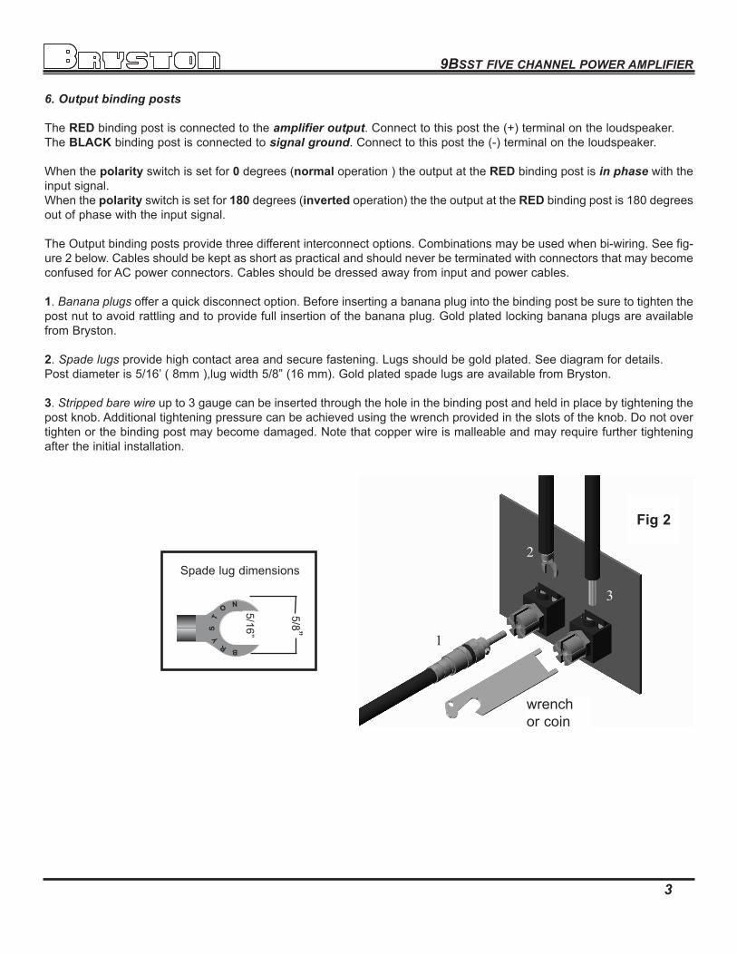
6. Output binding posts
TheREDbindingpostisconnectedtotheamplifier output.Connecttothispostthe(+)terminalontheloudspeaker.TheBLACKbindingpostisconnectedto signal ground.Connecttothispostthe(-)terminalontheloudspeaker.
Whenthepolarityswitchissetfor0degrees(normaloperation)theoutputattheREDbindingpostisin phasewiththeinputsignal.Whenthepolarityswitchissetfor180degrees(invertedoperation)thetheoutputattheREDbindingpostis180degreesoutofphasewiththeinputsignal.
TheOutputbindingpostsprovidethreedifferentinterconnectoptions.Combinationsmaybeusedwhenbi-wiring.Seefig-ure2below.CablesshouldbekeptasshortaspracticalandshouldneverbeterminatedwithconnectorsthatmaybecomeconfusedforACpowerconnectors.Cablesshouldbedressedawayfrominputandpowercables.1.Banana plugsofferaquickdisconnectoption.Beforeinsertingabananaplugintothebindingpostbesuretotightenthepostnuttoavoidrattlingandtoprovidefullinsertionofthebananaplug.GoldplatedlockingbananaplugsareavailablefromBryston.
2.Spade lugsprovidehighcontactareaandsecurefastening.Lugsshouldbegoldplated.Seediagramfordetails.Postdiameteris5/16’(8mm),lugwidth5/8”(16mm).GoldplatedspadelugsareavailablefromBryston.3.Stripped bare wireupto3gaugecanbeinsertedthroughtheholeinthebindingpostandheldinplacebytighteningthepostknob.Additionaltighteningpressurecanbeachievedusingthewrenchprovidedintheslotsoftheknob.Donotovertightenorthebindingpostmaybecomedamaged.Notethatcopperwireismalleableandmayrequirefurthertighteningaftertheinitialinstallation.
5/8”
5/16”
Fig 2
Spadelugdimensions
wrenchorcoin
1
2
3

9BSST FIVE CHANNEL POWER AMPLIFIER
4
Front Panel1. 'SST POWER' switchThefrontpanellabel'STPOWER',isatouchsensitivemembraneswitchusedtoapplyorremoveA/Clinepowertothe9BSSTcircuitry.Pushfirmlythecenteroftheswitchuntilthepower-upsequencebegins.Pushagainandthe9BSSTwillpower-down.(Note:therearcircuitbreakermustbeonforthe9BSSTtopower-up)
2. LED IndicatorsEach9BSSTchannelhasaLED indicatortomonitorthefollowingconditions: Unlit - indicateschannelhasnopower. Red - indicateschannelismuted(power-up-downsequence) GReen -indicateschanneloperationisnormal. FlashinG Red - indicateschannelclipping. ORanGe - indicateschannelthermalshutdown.Power up sequence Afterpushingthe'SSTPOWER'switch,eachchannelledwillturnfromunlittored(mute).Whenthepowersupplieshavestabilizedthechannelwillcomeoutofmuteandtheledwillchangetogreen(normaloperation).
Unlit led ( No power )The9BSSTchannelledwhenunlitindicatesnoA/Cmainspowerispresentatthechannel.Ifallchannelledindicatorsareunlitthe9BSSTprobablyneedsonlytobepoweredon.Asinglelednotlightingpossiblyindicatesblownchannelfuses.Whencheckingfusesswitchoffthecircuitbreakerontherearpanel,orunplugthepowercord.Useonlythespecifiedquick-acting4amp250V5mmx20mmfuses.Seepage6forthefuselocations.
Clipping ( flashing red )Clippingoccurswhenthechanneloutputlevelnolongercanfollowthelevelincreaseattheinput(Overdriveninputcon-dition).Whena9BSSTchannelisdrivenintoclippingthechannelledwillchangefromgreentoredthenbacktogreenwhenthelevelisreduced(FlashingRed).Momentaryclippingcanbetolerated,howeveritindicatesthatmaximumun-distortedpowerhasbeensurpassedandpotentialspeakerdamagemayresultifoverloadconditionspersist.Anyampli-fierthatisconstantlyoperatedintoclippingindicatesamorepowerfulamplifierisneededforthatapplication.
Thermal Shutdown ( orange )The9BSSTchannelhasthermalshutdowncircuitrytopreventdamageduetooverheating.Shouldthermalshutdownoccur,thechannelwillmute,andthechannelledwillturnorangeindicatingthiscondition.Whenthechannelhascooledtoasafeoperatingconditionthechannelwillreturntonormaloperation.PersistentThermalshutdownindicatesstepsneedtobetakentoincreaseairflowacrossthechannelorchannelsheatsink.(Alsoseeinstallationsectiononventilation).
2
1

9BSST FIVE CHANNEL POWER AMPLIFIER
5
Power Control PanelREAR POWER ENTRY PANEL1. Master circuit - breaker.The9BSSTusesamagnetic-tripcircuitbreaker(1)toprotecttheamplifier.Thisswitchshouldbe‘OFF’wheninstallingthe9BSST.Whenswitched‘OFF’allA/Cpowerisremovedfromtheamplifier,includingstandbypower.Thecircuitbreakerisnotthedaytodaypowerswitchandshouldbeswitchedandleft‘ON’aftertheinstallationiscomplete.Usethe‘STPOWER”switchoranexternalcontrolvoltagetoPower-uporPower-downtheamplifier.Shouldthebreakertrip,lowerorremovetheamplifierinputsignals.Switchthebreakertothe‘ON’position.Thenpowertheunitupnormally.The circuit breaker must be ‘ON’ at all times for the 9BSST to operate.
2. AC power input.Thisisahighcurrentplugforthepowercordreceptacle.Checkthatthevoltageratingattherightoftheconnectorconformswithyourlocality.Withthecircuitbreaker‘OFF’insertthepowercordintothe9BSST,thenplugtheotherendtoanapproprateA/Cpoweroutlet.
3. Power-Up ( Local / Auto switch. )A.In“Local”positioneitherthefrontpanel‘STPOWER”switchoranexternalvoltagecontrolsthepower-upofthe9BSST.B.“Auto”isusedwhenthe9BSSTispoweredfromaswitchedpoweroutlet.The‘STPOWER’switchand/orcontrolvoltagewillfunctionnormallyaftertheinitialpowerup.
4. External control voltage power up ( Local / external switch.)A.Topower-upthe9BSSTusinganexternalcontrolvoltage,Supplya4vto12vA/CorDCcontrolvoltagetothe‘IN’terminalsofconnector(5).Usepairedwireof22gaugeto18gaugesufficientinlengthbetweenthesourcedeviceandthe9BSST.(see‘W’)Selectswitch(4)to“External”.Theamplifierwillnowpower-uponlywhenthecontrolvoltageispresent(on).Immediatelyfollowingpowerup,thecontrolvoltagewillappearatthe’OUT’terminalsofconnector(5)forthecontrolofotherequipment.TheRemovalofthecontrolvoltage(0v)causesthe9BSSTtoturn‘off’andthecontrolvoltageatthe‘OUT’terminalsisinterrupted.B.Inthe“Local”settingofswitch(4)the9BSSTwillignorethecontrolvoltage,andpoweruponlybyusingthefrontpanel‘STPOWER’switch,orasinsection3above.Ifacontrolvoltageispresentatthe‘IN’terminalsitwillstillbeavailableatthe‘OUT’terminalsafterthepower-upsequence.
1/4”strip
Control voltage wire preparationfor screw terminal connector
18to22gaugewire
separate1”
CONTROL VOLTAGE SOURCENote:The‘OUT’terminalsareconnectedtothe‘IN’terminalsoncethe9BSSThaspowered-up.Thecontrolcurrentisdeterminedbythesource equipment.Thecarryingcurrentofthe‘OUT’relayis2amps.The9BSSTitselfdrawslessthan2mAfromthecontrolcurrentwhenoperating.
to other voltage controlled devices figureW

9BSST FIVE CHANNEL POWER AMPLIFIER
6
Rack Mounting Instructions
Removingthechannelsmakesrackmountingfareasierasthechassiswillbemuchlighter.Beforeremovinganyscrewsfromthe9BSSTbesurethepowercordisremovedfromtheunit.Removethescrewsindicatedonthetopandbottomviewsplustheonesdescribedonthesides.Pullgentlyonthechannelhandletoremovethechan-nel.Bepreparedtousebothhandstohandlethechannel.Itshouldnotbenecessarytoremovethepowerinputmodule.Install9BSSTchassisinrack.Carefullyreinstallthechannels.
REMOVE ALL 6-32 SCREWS ON THE BOTTOM.
Theremovalofthefeetshouldnotbenecessaryasclearancebelowthe
amplifierMUSTbeatleast1Uwhenrackmounting.
REMOVE 4 6-32 SCREWS
FROM THIS SIDE
REMOVE 3 3-32 SCREWS
FROM THIS SIDE
The9BSST19”versionmayberackmountedwithorwithouttheabilitytoremovethechannels.Ifremovalofthechan-nelsisdesiredthentheshippingscrewssecuringthechannelsneedtoberemoved.
TOP VIEW
BOTTOM VIEW
DO NOTREMOVESCREWSFROMRACKMOUNT
BRACKET
DO NOTREMOVESCREWSFROMRACKMOUNTBRACKET
REMOVE ALL 6-32 SCREWS ON THE
TOP
9BSST FIVE CHANNEL POWER AMPLIFIER
7
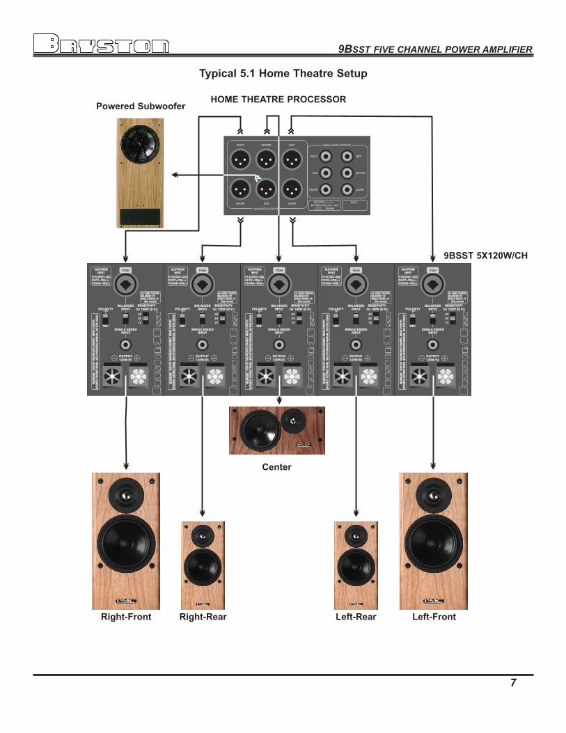
Typical 5.1 Home Theatre Setup
Left-RearRight-Rear
Center
Powered Subwoofer
Left-FrontRight-Front
HOME THEATRE PROCESSOR
9BSST 5X120W/CH
9BSST FIVE CHANNEL POWER AMPLIFIER
8

9BSST FIVE CHANNEL POWER AMPLIFIER
9
Typical Band-pass Noise Typical THD+N Harmonic Content
Power supply artifacts are all below -95 dBubalanced input with 23dB gain shown
The harmonic content of the 9BSST is all even order.
dBu: dB relative to a reference of 0.7746 Volts
Typical Frequency Response
8ohm120w<.01dB20Khz.
4ohm200w<.1dB20Khz.
Typical Phase Response
4 ohm 200w
8 ohm 120w
Typical THD+N Sweep
4 ohm 200w
8 ohm 120w
Typical IMD Sweep
8 ohm 120w
4 ohm 200w
9BSST FIVE CHANNEL POWER AMPLIFIER
10
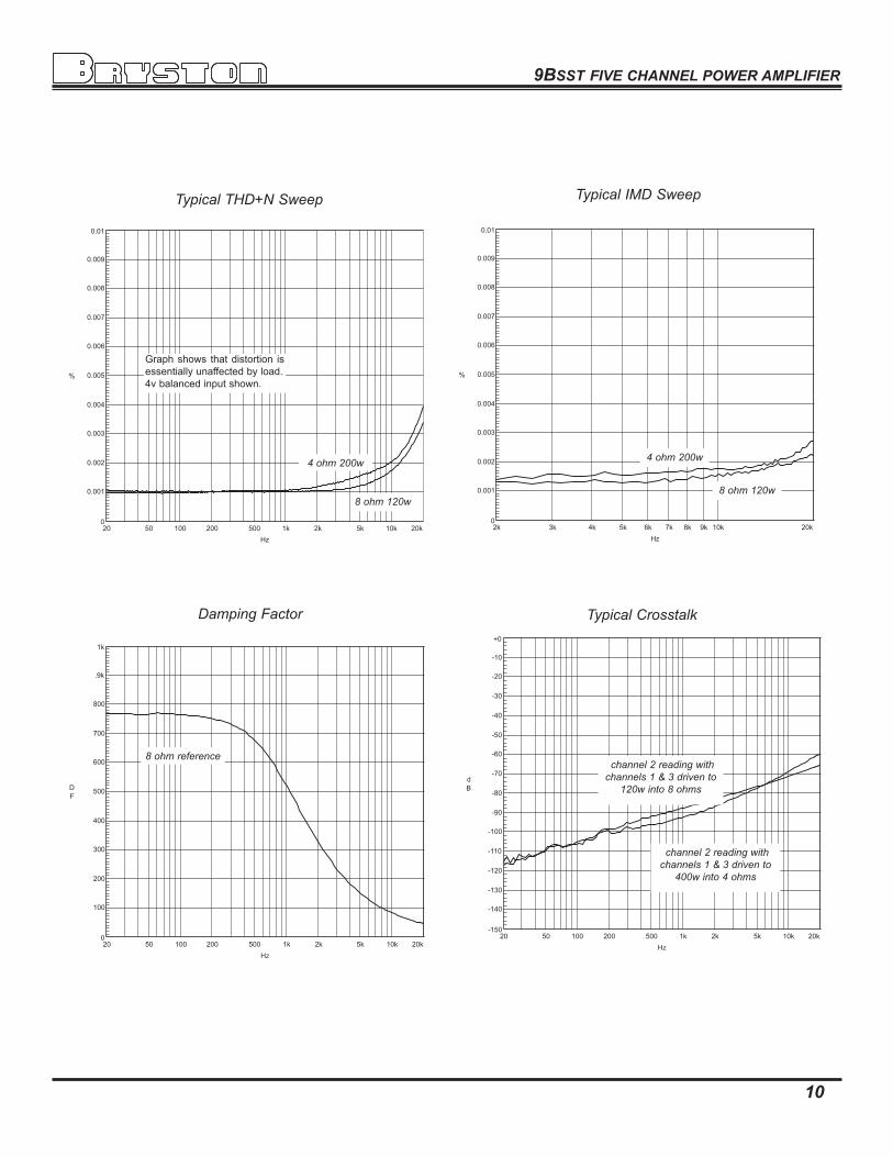
Graphshows thatdistortion isessentiallyunaffectedbyload.4vbalancedinputshown.
Damping Factor
8 ohm reference
Typical Crosstalk
channel 2 reading with channels 1 & 3 driven to
120w into 8 ohms
channel 2 reading with channels 1 & 3 driven to
400w into 4 ohms
BA
LA
NC
ED
INP
UT
4v
1v
2v
OU
TP
UT
25
0W
/8
XLR
/PH
ON
EIN
PU
T
Pin
1/S
LE
EV
E:
Pin
2/T
IP:
Pin
3/R
ING
:
GN
DP
OS
(+)
NE
G(–
)
WA
RN
ING
!R
ISK
OF
HA
ZA
RD
OU
S E
NE
RG
Y. MA
KE
PR
OP
ER
SP
EA
KE
R C
ON
NE
CT
ION
S.
SE
E O
PE
RA
TIN
G M
AN
UA
L B
EF
OR
E U
SIN
G.
HO
ME T
HEATR
E S
ET
TIN
GS
BA
LA
NC
ED
INP
UT
:S
ING
LE
EN
DE
D IN
PU
T:
Se
e m
an
ual fo
rfu
rthe
r de
tails
.
2V
1V
SE
NS
ITIV
ITY
for
100W
@ 8
PO
LA
RIT
Y
180
SIN
GL
E E
ND
ED
INP
UT
6B
/9B
AM
PLIF
IER
BR
IDG
ED
MO
DE
HO
OK
UP
6B
+9
B-B
RID
GE
D-H
OO
KU
P(R
P8
)PM
C.c
dr W
RP
1 N
OV
20
02
PUSH
0
BA
LA
NC
ED
INP
UT
4v
1v
2v
OU
TP
UT
25
0W
/8
XLR
/PH
ON
EIN
PU
T
Pin
1/S
LE
EV
E:
Pin
2/T
IP:
Pin
3/R
ING
:
GN
DP
OS
(+)
NE
G(–
)
WA
RN
ING
!R
ISK
OF
HA
ZA
RD
OU
S E
NE
RG
Y. MA
KE
PR
OP
ER
SP
EA
KE
R C
ON
NE
CT
ION
S.
SE
E O
PE
RA
TIN
G M
AN
UA
L B
EF
OR
E U
SIN
G.
HO
ME T
HEATR
E S
ET
TIN
GS
BA
LA
NC
ED
INP
UT
:S
ING
LE
EN
DE
D IN
PU
T:
Se
e m
an
ual fo
rfu
rthe
r de
tails
.
2V
1V
SE
NS
ITIV
ITY
for
100W
@ 8
PO
LA
RIT
Y
180
SIN
GL
E E
ND
ED
INP
UT
PUSH
0
Th
e s
am
e s
ign
al is
fed
into
bo
th a
mp
lifier c
han
nel in
pu
ts v
ia a
“Y
” a
dap
tor c
ab
le. N
ote
that th
e P
OLA
RITY
of
on
e c
han
nel is
the in
vers
e o
f the o
ther. T
HIS
IS
ES
SEN
TIA
L fo
r the a
mp
lifier to
op
era
te in
brid
ged
mo
de.
Failu
re to
IN
VER
T o
ne o
f the c
han
nels
rela
tive to
the o
ther w
ill resu
lt in z
ero
ou
tpu
t. It d
oes n
ot m
atte
r w
hic
h c
han
nel is
set to
zero
deg
rees a
nd
wh
ich
on
e is
set to
18
0 d
eg
rees, h
ow
ever, a
s lo
ng
as th
ey a
re
diffe
ren
t.W
hen
brid
gin
g tw
o c
han
nels
tog
eth
er th
e re
su
ltan
t ou
tpu
t will b
e in
cre
ased
by 6
dB
rela
tive to
the o
utp
ut
of a
sin
gle
ch
an
nel. T
o k
eep
the g
ain
of a
brid
ged
ch
an
nel th
e s
am
e a
s th
at o
f a s
ing
le c
han
nel, th
e
SEN
SITIV
ITY
sw
itch
sh
ou
ld b
e s
et to
a h
igh
er v
olta
ge s
ettin
g. F
or e
xam
ple
, if a s
ing
le c
han
nel is
set to
“1
V”
sen
sitiv
ity, th
en
bo
th th
e b
ridg
ed
ch
an
nels
wo
uld
be s
et to
“2
V”. L
ikew
ise, if a
sin
gle
ch
an
nel w
ere
set to
a
sen
sitiv
ity o
f “2
V”, th
en
the b
ridg
ed
ch
an
nels
wo
uld
be s
et to
“4
V”.
Wh
ile a
ny tw
o c
han
nels
can
be b
ridg
ed
, we re
co
mm
en
d th
at a
dja
cen
t ch
an
nels
b
e u
sed
(as s
ho
wn
) to
facilita
te th
e e
xte
rnal w
iring
betw
een
the c
han
nels
.N
ote
that o
nly
the P
OS
ITIV
E (
+) te
rmin
als
on
the 6
B p
ow
er a
mp
lifier m
od
ule
s
are
co
nn
ecte
d
to
the
sp
eaker.
A
g
rou
nd
w
ire
(1
6g
o
r h
eavie
r w
ire
reco
mm
en
ded
) m
ust b
e c
on
necte
d b
etw
een
the tw
o B
LA
CK
ou
tpu
t term
inals
o
n th
e 6
B a
mp
lifier c
han
nels
bein
g b
ridg
ed
. DO
NO
T C
ON
NEC
T A
NY
TH
IN
G E
LS
E
TO
EITH
ER
OF T
HES
E B
LA
CK
OU
TP
UT T
ER
MIN
ALS
! Th
e re
d (
po
sitiv
e) o
utp
ut te
rmin
al o
f the n
on
-inverte
d c
han
nel (
the o
ne w
ho
se
po
larity
is s
et to
zero
deg
rees) is
co
nn
ecte
d to
the s
peakers
po
sitiv
e (
+)
term
inal. T
he re
d (
po
sitiv
e) o
utp
ut te
rmin
al o
f the in
verte
d c
han
nel (
the o
ne
wh
ose p
ola
rity is
set to
18
0 d
eg
rees) is
co
nn
ecte
d to
the s
peakers
neg
ativ
e (
-)
term
inal.
To S
OU
RC
E S
IGN
AL
BA
LA
NC
ED
INP
UT
4v
1v
2v
OU
TP
UT
25
0W
/8
XLR
/PH
ON
EIN
PU
T
Pin
1/S
LE
EV
E:
Pin
2/T
IP:
Pin
3/R
ING
:
GN
DP
OS
(+)
NE
G(–
)
WA
RN
ING
!R
ISK
OF
HA
ZA
RD
OU
S E
NE
RG
Y. MA
KE
PR
OP
ER
SP
EA
KE
R C
ON
NE
CT
ION
S.
SE
E O
PE
RA
TIN
G M
AN
UA
L B
EF
OR
E U
SIN
G.
HO
ME T
HEATR
E S
ET
TIN
GS
BA
LA
NC
ED
INP
UT
:S
ING
LE
EN
DE
D IN
PU
T:
Se
e m
an
ual fo
rfu
rthe
r de
tails
.
2V
1V
SE
NS
ITIV
ITY
for
100W
@ 8
PO
LA
RIT
Y
180
SIN
GL
E E
ND
ED
INP
UT
PUSH
0
BA
LA
NC
ED
INP
UT
4v
1v
2v
OU
TP
UT
25
0W
/8
XLR
/PH
ON
EIN
PU
T
Pin
1/S
LE
EV
E:
Pin
2/T
IP:
Pin
3/R
ING
:
GN
DP
OS
(+)
NE
G(–
)
WA
RN
ING
!R
ISK
OF
HA
ZA
RD
OU
S E
NE
RG
Y. MA
KE
PR
OP
ER
SP
EA
KE
R C
ON
NE
CT
ION
S.
SE
E O
PE
RA
TIN
G M
AN
UA
L B
EF
OR
E U
SIN
G.
HO
ME T
HEATR
E S
ET
TIN
GS
BA
LA
NC
ED
INP
UT
:S
ING
LE
EN
DE
D IN
PU
T:
Se
e m
an
ual fo
rfu
rthe
r de
tails
.
2V
1V
SE
NS
ITIV
ITY
for
100W
@ 8
PO
LA
RIT
Y
180
SIN
GL
E E
ND
ED
INP
UT
PUSH
0
To
SO
UR
CE
SIG
NA
L
Wh
ile sin
gle
en
ded
o
r u
nb
ala
nced
in
pu
ts are
u
sed
h
ere
, b
ridg
ing
can
als
o b
e a
cco
mp
lish
ed
usin
g th
e b
ala
nced
inp
uts
as s
ho
wn
to th
e le
ft.
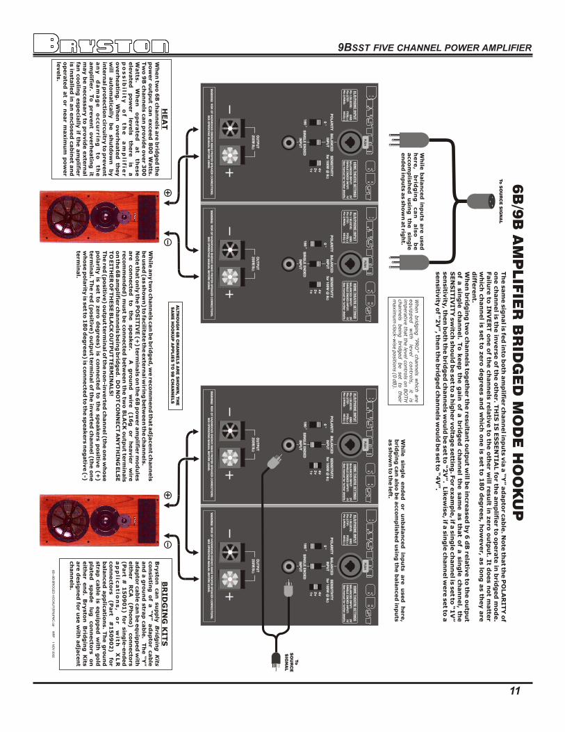
When brid
gin
g “P
RO
” channels
w
hic
h are
equip
ped
with
le
vel
contro
ls,
it is
im
pera
tive th
at th
e le
vel c
ontro
ls o
n B
OTH
channels
bein
g
brid
ged
be
set
to
their
maxim
um
clo
ck-w
ise p
ositio
ns (0
dB).
Wh
ile b
ala
nced
inp
uts
are
used
h
ere
, b
rid
gin
g
ca
n
als
o
be
acco
mp
lish
ed
u
sin
g
the
sin
gle
en
ded
inp
uts
as s
ho
wn
at rig
ht.
HEA
TW
hen
two
6B
ch
an
nels
are
brid
ged
the
po
wer o
utp
ut c
an
exceed
80
0 W
atts
. Tw
o 9
B c
han
nels
can
pro
vid
e o
ver 3
00
W
atts
. W
he
n
op
era
ted
a
t th
ese
ele
vate
d
po
wer
levels
th
ere
is
a
po
ss
ib
ility
o
f
th
e
am
plifie
r
overh
eatin
g.
Wh
en
o
verh
eate
d th
ey
will
au
tom
atic
ally
b
e
sh
utd
ow
n
by
inte
rnal p
rote
ctio
n c
ircu
itry to
pre
ven
t a
ny
d
am
ag
e
oc
cu
rrin
g
to
th
e
am
plifie
r. To
p
reven
t o
verh
eatin
g it
may b
e n
ecessary
to p
rovid
e e
xte
rnal
fan
co
olin
g e
sp
ecia
lly if th
e a
mp
lifier
is in
sta
lled
in a
n e
nclo
sed
cab
inet a
nd
o
pera
ted
at o
r near m
axim
um
po
wer
levels
.
BR
ID
GIN
G K
ITS
Bry
sto
n can
su
pp
ly B
ridg
ing
K
itsco
nsis
ting
o
f a “Y
” ad
ap
tor
cab
le
an
d a
gro
un
d s
trap
cab
le. T
he “
Y”
ad
ap
tor c
ab
le c
an
be e
qu
ipp
ed
with
eith
er
RC
A
(P
ho
no
)
co
nn
ecto
rs
(P
art
# 1
50
90
1) fo
r sin
gle
-en
ded
a
pp
lic
atio
ns
,
or
with
X
LR
co
nn
ecto
rs
(P
art
#1
50
90
2)
for
bala
nced
ap
plic
atio
ns. T
he g
rou
nd
stra
p cab
le is
eq
uip
ped
w
ith g
old
p
late
d
sp
ad
e
lug
co
nn
ecto
rs
on
eith
er
en
d.
Bry
sto
n B
ridg
ing
K
its
are
desig
ned
for u
se w
ith a
dja
cen
t ch
an
nels
.
ALT
HO
UG
H 6
B C
HA
NN
ELS
AR
E S
HO
WN
, TH
E
SA
ME
HO
OK
UP
AP
PLIE
S T
O 9
B C
HA
NN
ELS
11
9BSST FIVE CHANNEL POWER AMPLIFIER

9BSST FIVE CHANNEL POWER AMPLIFIER
12

9BSST FIVE CHANNEL POWER AMPLIFIER
15
9BSST FIVE CHANNEL POWER AMPLIFIER
13
Technical Specifications
Power Output 120wattsperchannelinto8ohms 200wattsperchannelinto4ohms
Gain Select and Sensitivity 29dB-1.1Vin=120W@8Ohms-(1VPosition) 23dB-2.2Vin=120W@8Ohms-(2VPosition) 17dB-4.4Vin=120W@8Ohms-(4VPosition)
Input Impedance 50Kohmssingleended 20Kohmsbalanced
Distortion <0.005%20Hzto20kHzat120wattsinto8ohms,IM or THD+noise <0.007%20Hzto20kHzat200wattsinto4ohms
Noise Measuredwithinputshorted-20Hzto20kHz. >110dBbelowratedoutput29dBgain(-73dBu) >113dBbelowratedoutput23dBgain(-76dBu) >116dBbelowratedoutput17dBgain(-79dBu)
Slew Rate >60voltspermicrosecondPower Bandwidth <1Hztoover100kHz
Damping Factor Over500at20Hz,ref.8ohms
Dimensions Rackmountversion 48.3x13.3x48.3cm-19”x5.25”x19“withhandles- mountedrackdepth-43.2cm-17"17”version 43.2x13.3x44.5cm-17”x5.25”x17.5“Weight: approx.28kg-62lbs
Power Consumption &Heat Load
singlechannel120W@8ohms- 242Watts 5channels@120W@8ohms- 1397Watts Max.HeatDissipation8ohms- 2720Btu/Hr.
singlechannel200W@4ohms- 422Watts 5channels@200W@4ohms- 2295Watts Max.HeatDissipation4ohms- 4420Btu/Hr. AtIdle- 192Watts
IMPORTANT SAFETY INSTRUCTIONSThe lightning flash with arrowhead symbol within an equilateral triangle, is intended to alert the user to the presence of un-insulated “dangerous voltage “ within the product’s enclosure that may be of sufficient magnitude to constitute a risk of electric shock to persons.
The exclamation point within an equilateral triangle is intended to alert the user to the presence of important operating and maintenance (servicing) instructions in the literature accompanying the product.
1. Read these instructions.2. Keep these instructions.3. Heed all warnings.4. Follow all instructions.5. Do not use this apparatus near water.6. Clean only with dry cloth.7. Do not block any ventilation openings. Install in accordance with the manufacturer’s instructions.8. Do not install near any heat sources such as radiators, heat registers, stoves, or other apparatus (including amplifiers) that produce heat.9. Do not defeat the safety purpose of the polarized or grounding-type plug. A polarized plug has two blades with one wider than the other. A
grounding type plug has two blades and a third grounding prong. The wide blade or the third prong are provided for your safety. If the pro-vided plug does not fit into your outlet, consult an electrician for replacement of the obsolete outlet.
10. Protect the power cord from being walked on or pinched particularly at plugs, convenience receptacles, and the point where they exit from the apparatus.
11. Only use attachments/accessories specified by the manufacturer.12. Use only with the cart, stand, tripod, bracket, or table specified by the manufacturer, or sold with the apparatus. When a cart is
used use caution when moving the cart/apparatus combination to avoid injury from tip-over.13. Unplug this apparatus during lightning storms or when unused for long periods of time.14. Refer all servicing to qualified service personnel. Servicing is required when the apparatus has been damaged in any way, such as power-
supply cord or plug is damaged, liquid has been spilled or objects have fallen into the apparatus, the apparatus has been exposed to rain or moisture, does not operate normally, or has been dropped.
WARNING: TO REDUCE THE RISK OF FIRE OR ELECTRIC SHOCK, DO NOT EXPOSE THIS APPARATUS TO RAIN OR MOISTURE.DO NOT EXPOSE THIS EQUIPMENT TO DRIPPING OR SPLASHING AND ENSURE THAT NO OBJECTS FILLED WITH LIQUIDS, SUCH AS VASES, ARE PLACED ON THE EQUIPMENT.TO COMPLETELY DISCONNECT THIS EQUIPMENT FROM THE AC MAINS, DISCONNECT THE POWER SUPPLY CORD PLUG FROM THE AC RECEPTACLE.THE MAINS PLUG OF THE POWER SUPPLY CORD SHALL REMAIN READILY OPERABLE.
BRYSTON LIMITED WARRANTYBryston analog audio circuits are warranted to be free from manufacturing defects for twenty (20) years from the original date of manufacture. The warranty includes parts and labour.Bryston Digital circuits and cables are warranted for five years from the original date of manufacture. The warranty includes parts and labour. Bryston products having motorized moving parts, excluding motorized volume controls, are warranted for three years from the original date of manu-facture. The warranty includes parts and labour. Bryston will remedy the problem by repair or replacement, as we deem necessary, to restore the product to full performance. Bryston will pay ship-ping costs one way (usually the return portion) during the first three years of warranty coverage.In the event of a defect or malfunction, contact Bryston’s repair centers for return authorization. Products must be returned using original packaging material only. Packing material may be purchased from Bryston if necessary. This warranty is considered void if the defect, malfunction or failure of the product or any component part was caused by damage (not resulting from a defect or malfunction) or abuse while in the possession of the customer. Tampering by persons other than factory authorized service personnel or failure to fully comply with Bryston operating instructions voids the warranty. This warranty gives you specific legal rights and you may also have other rights which may vary from province to province and country to country.As of 2006-02-22 Bryston will only warranty Bryston products purchased through authorized Bryston dealers. Bryston products with a date code of 0608 or higher (date code format is “yyww”, where “yy” is the two least significant digits of the year and “ww” is the week of the year) must be accompanied by a copy of the bill-of-sale from a Bryston authorized dealer to qualify for warranty service. The warranty is transferable from the original owner to a subsequent owner as long as a copy of the bill-of-sale from the original authorized Bryston dealer accompanies the re-sale. The copy of the bill of sale to any subsequent owner need ONLY include the Name of the Bryston Authorized Dealer and the Model and Serial number of the Bryston product The warranty will only be honored in the country of the original purchase unless otherwise pre-authorized by Bryston.
Postal address: P.O.BOX2170,Stn.Main PETERBOROUGH,ONTARIO CANADAK9J7Y4Courier address: 677NEALDRIVE PETERBOROUGH,ONTARIO CANADAK9J6X7
PHONE: 705-742-5325FAX: 705-742-0882E-mail: [email protected]
79COVENTRYST.,Suite5NEWPORT,VERMONTU.S.A.05855-2100
PHONE: 802-334-1201FAX: 802-334-6658E-mail: [email protected]
BRYSTON SERVICE in CANADA: BRYSTON SERVICE in the USA:
contact your local distributor or
CHECK OUR WEB SITE: www.bryston.ca E-MAIL BRYSTON DIRECTLY: [email protected] BRYSTON DIRECTLY: 01-705-742-0882PHONE BRYSTON DIRECTLY: 01-705-742-5325
BRYSTON SERVICE outside Canada and the USA:
9BSST_MANUAL_20070108


