19
Power Budget Extender For EPON Xifang Zhang, Zhiming Fu Jidong Xu, Marek Hajduczenia ZTE Corporation IEEE 802.3 interim meeting, Minneapolis, MN, USA May, 2012
Power Budget Extender For EPON
Xifang Zhang, Zhiming Fu
Jidong Xu, Marek Hajduczenia
ZTE Corporation
IEEE 802.3 interim meeting, Minneapolis, MN, USA May, 2012

Agenda
Background and Overview
Overview of Power Budget Extender (PBEx)
PBEx for Coexistence Mode
Comparison and Proposed Solutions
.
Background
1:64+ Split Ratio Larger split ratio (e.g. 1:128, 1:256 or more) is needed in dense populated
metro areas to share OLT port cost among larger number of subscribers The actual installation ratio of EPON is very low at the beginning
Several PON ports need to be combined to increase the efficiency of OLT port
Longer Reach Longer reach is needed under some circumstances (see slides from CFI and SG
meetings)
Reduce the cost The OPEX cut down is desired as well as expansion of service areas
Review Power budget of 24 dB is defined in 802.3ah to support 20 km @1:16 Power budget of 29 dB is defined in 802.3av to support 20 km @1:32 Power budget of 33 dB to support 20 km @1:64 is under discussion in 802.3bk Power budget beyond 33 dB can’t be satisfied just now

.
Optical loss budget of 33 dB or less can be achieved in a cost-efficient
way by increasing the Tx launch power and/ or improving Rx sensitivity
or adding FEC to PCS
PBEx is a preferred choice when optical loss budget needs to be
increased considerably above 33 dB
Solutions
Agenda
Background and Overview
Overview of Power Budget Extender (PBEx)
PBEx for Coexistence Mode
Comparison and Proposed Solutions
.
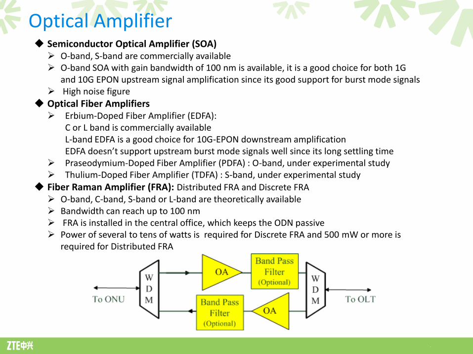
Optical Amplifier Semiconductor Optical Amplifier (SOA) O-band, S-band are commercially available O-band SOA with gain bandwidth of 100 nm is available, it is a good choice for both 1G
and 10G EPON upstream signal amplification since its good support for burst mode signals High noise figure
Optical Fiber Amplifiers Erbium-Doped Fiber Amplifier (EDFA):
C or L band is commercially available L-band EDFA is a good choice for 10G-EPON downstream amplification EDFA doesn’t support upstream burst mode signals well since its long settling time
Praseodymium-Doped Fiber Amplifier (PDFA) : O-band, under experimental study Thulium-Doped Fiber Amplifier (TDFA) : S-band, under experimental study
Fiber Raman Amplifier (FRA): Distributed FRA and Discrete FRA O-band, C-band, S-band or L-band are theoretically available Bandwidth can reach up to 100 nm FRA is installed in the central office, which keeps the ODN passive Power of several to tens of watts is required for Discrete FRA and 500 mW or more is
required for Distributed FRA
.
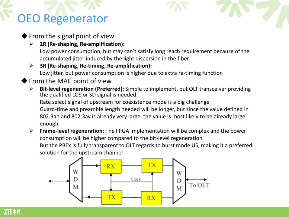
From the signal point of view 2R (Re-shaping, Re-amplification):
Low power consumption, but may can’t satisfy long reach requirement because of the accumulated jitter induced by the light dispersion in the fiber
3R (Re-shaping, Re-timing, Re-amplification): Low jitter, but power consumption is higher due to extra re-timing function
From the MAC point of view Bit-level regeneration (Preferred): Simple to implement, but OLT transceiver providing the qualified LOS or SD signal is needed
Rate select signal of upstream for coexistence mode is a big challenge Guard-time and preamble length needed will be longer, but since the value defined in 802.3ah and 802.3av is already very large, the value is most likely to be already large enough
Frame-level regeneration: The FPGA implementation will be complex and the power consumption will be higher compared to the bit-level regeneration But the PBEx is fully transparent to OLT regards to burst mode US, making it a preferred solution for the upstream channel
OEO Regenerator
.
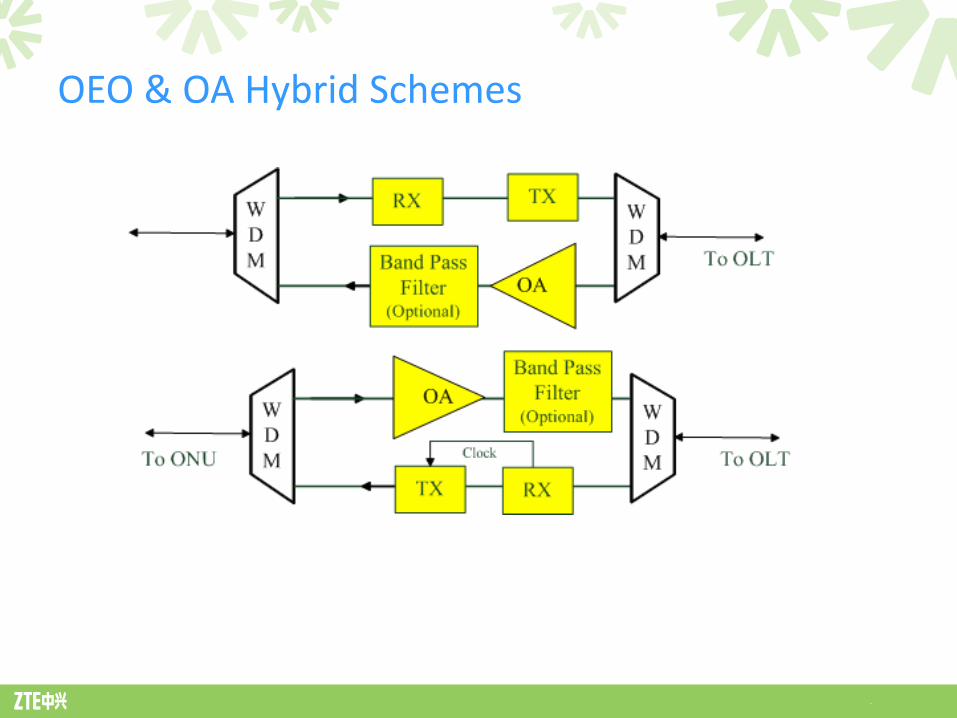
OEO & OA Hybrid Schemes
Agenda
Background and Overview
Overview of Power Budget Extender (PBEx)
PBEx for Coexistence Mode
Comparison and Proposed Solutions

.
The PBEx should support 1G-EPON and 10G-EPON coexistence mode with a longer reach and larger split ratio (e.g. 40+ km), with the split ratio of 1:128+
Coexistence Mode
.
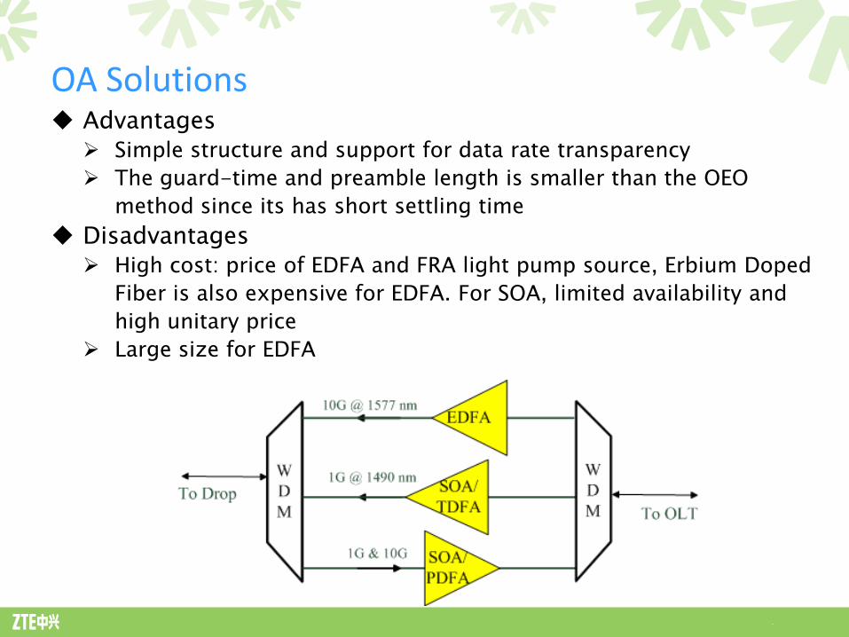
Advantages Simple structure and support for data rate transparency
The guard-time and preamble length is smaller than the OEO
method since its has short settling time
Disadvantages High cost: price of EDFA and FRA light pump source, Erbium Doped
Fiber is also expensive for EDFA. For SOA, limited availability and
high unitary price
Large size for EDFA
OA Solutions

.
OEO Solutions
Advantages Low cost, no ASE (Amplified Spontaneous Emission) noise
Disadvantages Generation of the control signal of the upstream on/off switching is a big challenge in EPON (needs tracking of upstream grants)
The guard-time and preamble length needed will be longer than in OA, but may within the value defined in 802.3
Rate transparency is not supported (not very future-proof)

.
O-Band SOA is a good choice for the upstream optical amplification because of its good support for burst mode signals
The downstream continuous signal can be handled using the OEO method because of its low cost and demonstrated technical feasibility
OA & OEO Hybrid Solutions

Agenda
Background and Overview
Overview of Power Budget Extender (PBEx)
PBEx for Coexistence Mode
Comparison and Proposed Solutions
.
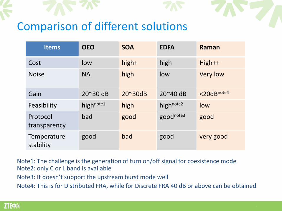
Comparison of different solutions
Note1: The challenge is the generation of turn on/off signal for coexistence mode Note2: only C or L band is available
Note3: It doesn’t support the upstream burst mode well
Note4: This is for Distributed FRA, while for Discrete FRA 40 dB or above can be obtained
Items OEO SOA EDFA Raman
Cost low high+ high High++
Noise NA high
low
Very low
Gain 20~30 dB 20~30dB 20~40 dB <20dBnote4
Feasibility highnote1 high highnote2 low
Protocol transparency
bad good goodnote3 good
Temperature stability
good bad good very good
.
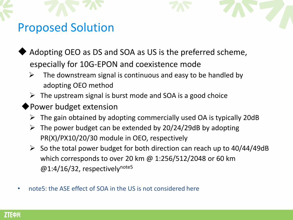
Adopting OEO as DS and SOA as US is the preferred scheme,
especially for 10G-EPON and coexistence mode The downstream signal is continuous and easy to be handled by
adopting OEO method
The upstream signal is burst mode and SOA is a good choice
Power budget extension The gain obtained by adopting commercially used OA is typically 20dB
The power budget can be extended by 20/24/29dB by adopting
PR(X)/PX10/20/30 module in OEO, respectively
So the total power budget for both direction can reach up to 40/44/49dB
which corresponds to over 20 km @ 1:256/512/2048 or 60 km
@1:4/16/32, respectivelynote5
• note5: the ASE effect of SOA in the US is not considered here
Proposed Solution

.
Items Unit Items Unit
Number of Fiber, Fiber type -
Attenuation range for 1480-1500 nm from OLT to PBEx dB Maximum attenuation for 1260-1360 nm from PBEx to OLT dB
Attenuation range for 1575-1580 nm from OLT to PBEx dB Minimum attenuation for 1260-1280nm from PBEx to OLT dB
Attenuation range for 1480-1500 nm from PBEx to ONU dB Maximum attenuation for 1260-1360 nm from ONU to PBEx dB
Attenuation range for 1575-1580 nm from PBEx to ONU dB Minimum attenuation for 1260-1280nm from ONU to PBEx dB
Maximum optical path penalty from OLT to PBEx dB Maximum optical path penalty PBEx to ONU dB
PBEx receiver - PBEx transmitter
Minimum Sensitivity for DS 1G signal dBm Average launch power (max,min) for DS 1G signal dBm
Minimum Sensitivity for DS 10G signal dBm Average launch power (max,min) for DS 10G signal dBm
Minimum overload for DS 1G signal dBm Average launch power (max,min) for US 1G signal dBm
Minimum overload for DS 10G signal dBm Average launch power (max,min) for US 10G signal dBm
Minimum Sensitivity for US 1G signal dBm Maximum ASE output power in 1255-1365 (for 1G)/1255-1285
(for 10G) nm launched toward OLT relative to signal output
power
dB
Minimum Sensitivity for US 10G signal dBm Maximum ASE output power in 1200-1255 nm and 1285-1400
nm (for 10G)/1365-1400 nm launched toward OLT relative to
signal output power
dB
Minimum overload for US 1G signal dBm Maximum ASE output power in 1400-1600 nm band for US dBm
Minimum overload for US 10G signal dBm
Bit Error Ratio -
PMD Layer parameters of PBEx

.
Items Unit Items Unit
OLT transmitter ONU transmitter
All parameters same as 802.3ah and 802.3av
All parameters in 802.3ah and
802.3av unless specified here
same as 802.3ah and 802.3av
OLT receiver Dispersion range (for 10G) ps/nm
All parameters in 802.3ah and
802.3av unless specified here
same as 802.3ah and 802.3av
ONU receiver
Bit error ratio - All parameters same as 802.3ah and 802.3av
Immunity against incident ASE
power (optical power bias
tolerance) in 1255-1365 nm band
at x dB additional penalty: ASE
power relative to modulated
signal power
dB PBEx timing
Additional penalty due to ASE-
related power bias at OLT
receiver
dB Maximum SOA settling time ns
PMD Layer parameters of OLT and ONU

Thanks!


