Power Congestion Management of Transmission
System Using Unified Power Flow Controller
Shaifali Jain ITM University, Gurgaon, Haryana
Email: [email protected]
Ragi Jain MMEC, Maharishi Markandeshwar University, Mullana, Ambala, Haryana
Email: [email protected]
Abstract—Line outage, congestion, cascading line tripping
and system stability loss are the major problems faced by a
power system. Solution to this problem is the use of FACTS
devices especially Unified Power Flow Controller (UPFC).
UPFC can uphold the voltage magnitude, phase angle and
line impedance of a power system transmission line. In this
paper, performance of unified power flow controller is
investigated using MATLAB based commercial power
system simulation software Power System Toolbox (PST) in
various modes of operation. With the help of model of power
system in MATLAB, and by installing UPFC in transmission
system, its use as power flow controller and voltage injector,
is used to relieve power congestion in transmission system.
Index Terms—FACTS, UPFC, power flow controller
I. INTRODUCTION
FACTS is defined as Flexible alternating current
transmission systems incorporating power electronics
based devices to enhance controllability and increase
power transfer capability. The controllers that are
designed based on the concept of FACTS technology to
improve the power flow control; stability and reliability
are known as FACTS controllers. These controllers were
introduced depending on the type of power system
problems. Some of these controllers were capable of
addressing multiple problems in a power system but some
are limited to solve for a particular problem.
The maintenance and reliability of power system is the
major issue in today’s competitive environment. With
increase demand and supply in power system, maintaining
stability and security in this emerging electricity market.
The solution is the use of FACTS devices especially the
use of UPFC [1]. UPFC belong to last generation of
FACTS devices they are capable of controlling
simultaneously all three parameters of lines power flow
(line impedance, voltage and phase angle).
The Unified Power Flow Controller (UPFC) concept
was proposed by L. Gyugyi [2] in 1991. It is used to
control the active and reactive powers flow through
Manuscript received June 20, 2015; revised March 21, 2016.
transmission lines. Such FACTS device is a combination
of two old FACTS devices i.e. The Static Synchronous
Compensator (STATCOM) and the Static Synchronous
series Compensator (SSSC). The above said two devices
work as Voltage Source Inverters (VSI’s) connected
respectively in shunt with the transmission line through
shunt transformer and in series with series transformer,
these two devices are connected to each other by a
common dc link including a storage capacitor. The first
Unified Power Flow Controller (UPFC) in the world, with
a total rating of ±320MVA, was commissioned in
mid-1998 at the Inez station of the American Electric
Power (AEP) in Kentucky for voltage support and power
flow control. [3]-[6]
Power systems today are highly complex and the
requirements to provide a stable, secure, controlled and
economic quality of power are becoming vitally important
with the rapid growth in industrial area. To meet the
demand of power in a power system it is essential to
increase the transmitted power either by installing new
transmission lines or by improving the existing
transmission lines by adding new devices. [7] Installation
of new transmission lines in a power system leads to the
technological complication such as economic and
environmental disorders. Considering these factors power
system engineers concentrated the research process to
modify the existing transmission system instead of
constructing new transmission lines. The main objective to
introduce FACTS Technology is to increase the power
transfer capability of a transmission network in a power
system, provide the direct control of power flow over
designated transmission routes, provide secure loading of
a transmission lines near the thermal limits, improve the
damping of oscillations as this can threaten security or
limit usage line capacity.
II. FACTS SYSTEM
A. Advantages of FACTS Devices
FACTS controllers can be used for various applications
to enhance power system performance.
International Journal of Electronics and Electrical Engineering Vol. 4, No. 6, December 2016
©2016 Int. J. Electron. Electr. Eng. 554doi: 10.18178/ijeee.4.6.554-558
transmission line has negative impact on the environment.
FACTS devices help to distribute the electrical energy
more economically through better utilization of existing
installation there by reducing the need for additional
transmission lines.
created due to long length of transmission lines,
interconnected grid, changing system loads and line faults
in the system. These instabilities results in reduced line
flows or even line trip. FACTS devices stabilize
transmission systems with increased transfer capability
and reduced risk of line trips.
high quality of electricity supply including constant
voltage and frequency, and no supply interruptions.
Voltage dips, frequency variations or the loss of supply
can lead to interruptions in manufacturing processes with
high economic losses. FACTS devices can help to provide
the required quality of supply.
transmission lines that take several years to construct,
FACTS installation requires only 12 to 18 months. FACTS
installation has the flexibility as it requires small land area.
cost is very minimum as the number of transmission line
increases, the probability of fault occurring in a line is also
high. So, by utilizing the transmission systems optimally
with the use of FACTS, the total number of line fault is
minimized, thus reducing the maintenance costs.
B. FACTS Devices Used in Power System
1) Static VAR Compensator (SVC)
It is a variable impedance device where the current
through the reactor is controlled using back to back
connected thyristor valves. The application of thyristor
valve technology to SVC is an offshoot of the
developments in HVDC technology. The major difference
is that thyristor valves used in SVC are rated for lower
voltages as the SVC is connected to an EHV line through
a step down transformer or connected to an EHV line
through a step down transformer or connected to the
tertiary winding of a power transformer. The application
of SVC was initially for load compensation of fast
changing loads such as steel mills and arc furnaces.
2) Static Synchronous Compensator (STATCOM)
A STATCOM is a device for reactive power control and
is connected in parallel to the electric network with a
transformer. STATCOM has a VSC (Voltage Source
Converter) interface, and the DC-voltage support is
provided with capacitors of relatively small energy storage,
so the active power exchange is zero in steady-state. In
practice there will be a little active power interchange due
to losses. The basic principle of operation for the
STATCOM is to compare the voltage in the system and the
terminal voltage on the VSC, and control the phase angle
and amplitude on the voltage drop over the transformer
inductance. When the voltage in the electric system is
lower than the terminal voltage on the VSC, the
STATCOM will generate reactive power, the STATCOM
works in capacitive mode. If the voltage on the VSC is
lower than the voltage in the electric network, the
STATCOM will absorb reactive power, the STATCOM
works in inductive mode. If the voltage of the electric
network and the terminal voltage on the VSC are equal,
there will not be any reactive flow in the STATCOM. This
device can serve the best solution for meeting the grid
code demands. The continuous increase of installed wind
power seen during recent years has forced the
Transmission System Operators (TSO) to tighten their grid
connection rules - also known as Grid Code - in order to
limit the effects of power parks on network quality and
stability. These new rules demand that power plants of any
kind support the electricity network throughout their
operation. Key issues are steady state and dynamic
reactive power capability, continuously acting voltage
control and fault ride through behavior. Some commonly
used turbine designs have some limits in terms of
achieving Grid Code compliance in several countries.
3) Thyristor Controlled Series Capacitor (TCSC)
A TCSC is a capacitive reactance compensator, which
consists of a series capacitor bank shunted by a thyristor
controlled reactor in order to provide a smoothly variable
series capacitive reactance. Even through a TCSC in the
normal operating range in mainly capacitive, but it can
also be used in an inductive mode. TCSC controls the line
impedance by changing the firing angle of the thyristors.
A TCSC segment consists of a series stable capacitor that
is coupled in parallel to a Thyristor Controlled Reactor
(TCR).
A TCR comprises of a pair of anti-parallel thyristors
that are joined in series with an inductor. In a TCSC, a
Metal Oxide Varistor (MOV) besides a bypass breaker is
connected in parallel to the stationary capacitor for
overvoltage fortification. A complete compensation
system may be made up of numerous of these units.
4) Unified Power Flow Controller (UPFC)
A Unified Power Flow Controller is an electrical device
for providing fast- active reactive power compensation
high voltage electricity transmission networks. It uses a
pair of three phase controllable bridges to produce current
that is injected into a transmission line using a series
transformer. The controller can control active and reactive
power flows in a transmission line. The UPFC uses solid
state devices, which provide functional flexibility,
generally not attainable by conventional thyristor
controlled systems. The UPFC is a combination of a static
synchronous compensator (STATCOM) and a Static
Synchronous Compensator (SSSC) coupled via a common
DC voltage link. The UPFC is a multipurpose and most
robust FACTS device. UPFC is also known as the most
wide-ranging multivariable Flexible AC Transmission
System (FACTS) controller. The Unified Power Flow
Controller (UPFC) controls the power flow in the
transmission systems by controlling the impedance, phase
angle and voltage magnitude. This controller exhibits
large benefits both in terms of static and dynamic
operation of the power system. [8] It also conveys
International Journal of Electronics and Electrical Engineering Vol. 4, No. 6, December 2016
©2016 Int. J. Electron. Electr. Eng. 555
Environmental benefit: The construction of new
Increased stability: Instabilities in power system are
Increased quality of supply: Modern industries require
Flexibility and uptime: Unlike new overhead
Reduced maintenance cost: The FACTS maintenance
innovative challenges in the power system sector mainly in
power system design. The elementary UPFC consists of
two inverter; wherein one is connected in series to the
transmission line while the other is in parallel with the
transmission line. The UPFC consists of two voltage
source converters; series and shunt converter, which are
connected to each other with a common dc link. Series
converter or Static Synchronous Series Compensator
(SSSC) is used to add controlled voltage magnitude and
phase angle in series with the line, while shunt converter is
used to provide reactive power to the ac system. Each of
the branches consists of a transformer and power
electronic converter. These two voltage source converters
share a common dc capacitor. The energy storing capacity
of this dc capacitor is generally small. Therefore, active
power drawn by the shunt converter should be equal to the
active power generated by the series converter. The
reactive power in the shunt or series converter can be
chosen independently, giving greater flexibility to the
power flow control.
III. UNIIFIED POWER FLOW CONTROLLER
A. UPFC Description and Operation
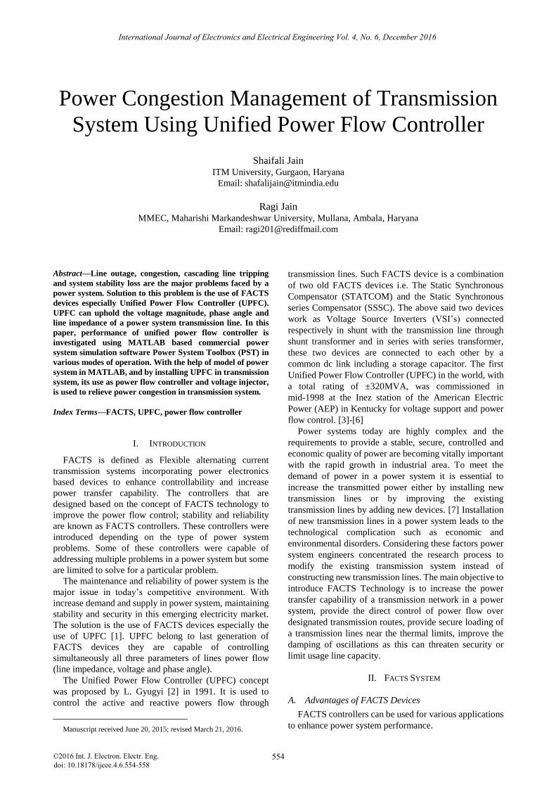
The unified power flow controller consist of two
switching converters, which in the implementations
considered are voltage source inverters using the Gate
Turn Off (GTO) or insulated gate bipolar thyristor valves,
as shown in Fig. 1. These inverters labelled “Inverter 1”
and “Inverter 2” are operated from a common dc link
provided by a dc storage capacitor. This arrangement
functions as an ideal ac to ac power converters in which
real power can freely flow in either direction between the
ac terminals of the two inverters and each inverter can
independently generate or absorb reactive power at its own
ac output terminals.
Figure 1. UPFC system
Inverter 2 provides the main function of the UPFC by
injecting an ac voltage Vpq with controllable magnitude
Vpq (0≤Vpq≤Vpqmax) and phase angle ρ (0≤ρ≤360°), at the
power frequency, in series with the line via an insertion
transformer. This injected voltage can be considered
essentially as a synchronous ac voltage sources. The
transmission line current flows through this voltage source
resulting in real and reactive power exchange between it
and the ac system. The real power exchanged at the ac
terminal (i.e., at the terminal of the insertion transformer)
is converted by the into dc power which appears at the dc
link as positive or negative real power demand. The
reactive power exchanged at the ac terminal is generated
internally by the inverter. [9], [10]
The basic function of inverter 1 is to supply or absorb
the real power demanded by inverter 2 at the common dc
link. This dc link power is converted back to ac and
coupled to the transmission line via a shunt- connected
transformer. Inverter 1 can also generate or absorb
controllable reactive power, if it is desired, and thereby it
can provide independent shunt reactive compensation for
the line. Thus, inverter 1 can be operated at a unity power
factor or be controlled to have a reactive power exchange
with the line independently of the reactive power
exchanged by inverter 2. This means that there is no
continuous reactive power flow through the UPFC.
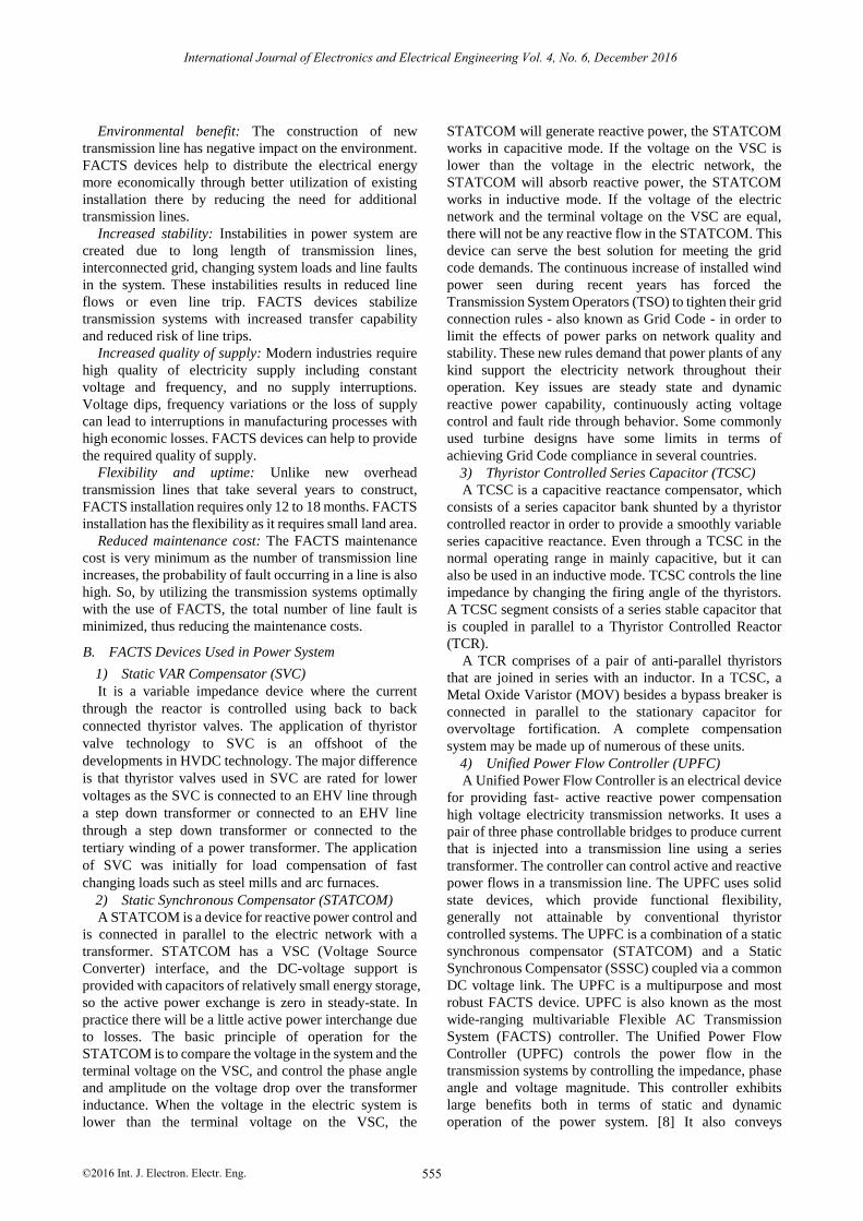
B. Details of Power System
A UPFC is used to control the power flow in a
500KV/230KV transmission system. The system consist
of five buses (B1-B5) interconnected through three
transmission line (L1, L2, L3) and two 500KV/230KV
transformer banks Tr1 and Tr2 as shown in Fig. 2. There
are two power plants located on 230KV system generating
a total of 1500MW which is transmitted to a 500KV
15000MVA equivalent and to a 200MW load connected
at bus B3. Two power plants consist of a speed regulator,
an excitation system and a power system stabilizer. Total
generating capacity of power plant 2 is 1200MW and in
normal operation, most of the generated capacity is
transmitted to 500KV equivalent through two 400MVA
transformers connected between buses B4 and B5. In this
thesis a contingency case is considered where only two
transformers will be considered out of the three available
(Tr2=2*400=800MVA). The load flow shows that most of
the power generated by plant 2 is transmitted through the
800MVA transformer bank (899MW of 1000MW) and
that 96MW is circulating in the loop. Transformer Tr2 is
overloaded by 99MVA. UPFC used in this power system
is used to relieve power congestion.
Figure 2. Specifics of power system
International Journal of Electronics and Electrical Engineering Vol. 4, No. 6, December 2016
©2016 Int. J. Electron. Electr. Eng. 556
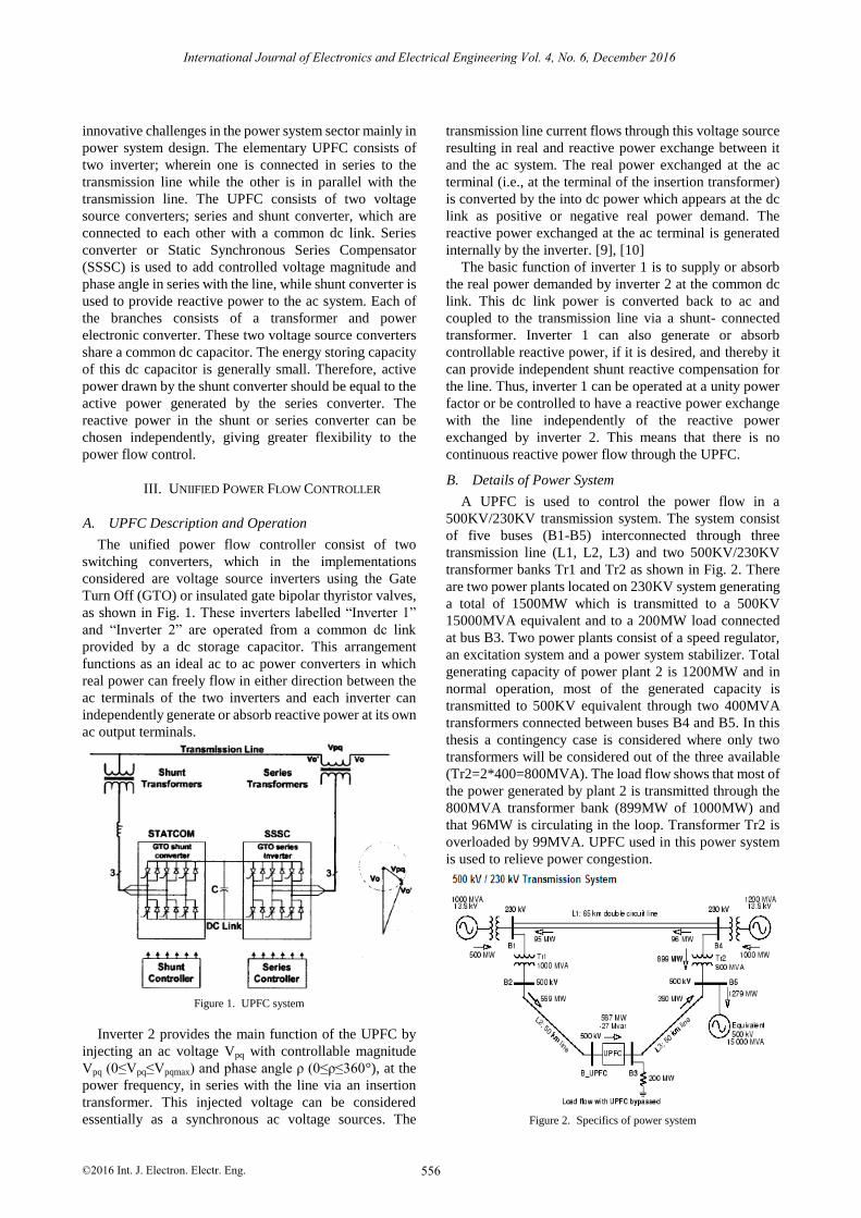
C. Power Control with the UPFC
Initially the bypass breaker is closed and the resulting
natural power flow at bus B3 is 587MW and -27Mvar. The
P ref block is programmed with an initial active power of
5.87PU corresponding to the natural flow. Then at t=10s,
P ref is increased by 1PU (100MW) from 5.87 PU to
6.87PU, while Q ref is kept constant at -0.27PU.
Figure 3. Simulation result of power flow control with UPFC
On running the simulation and looking on the “UPFC”
scope how P and Q measured at bus B3 follow reference
values. At t=5s, when bypass breaker is opened the natural
power is diverted from the bypass breaker to the UPFC
series branch without noticeable transient. At t=10s, the
power increases at a rate of 1PU/S. It takes one second for
the power to increase to 687MW. This 100MW increase
of active power at bus B3 is achieved by injecting a series
voltage of 0.089PU with an angle of 94 degrees. This
result in an approximate 100MW decrease in active power
flowing through Tr2 (from 899MW to 796MW), which
now carries an acceptable load as shown in Fig. 3.
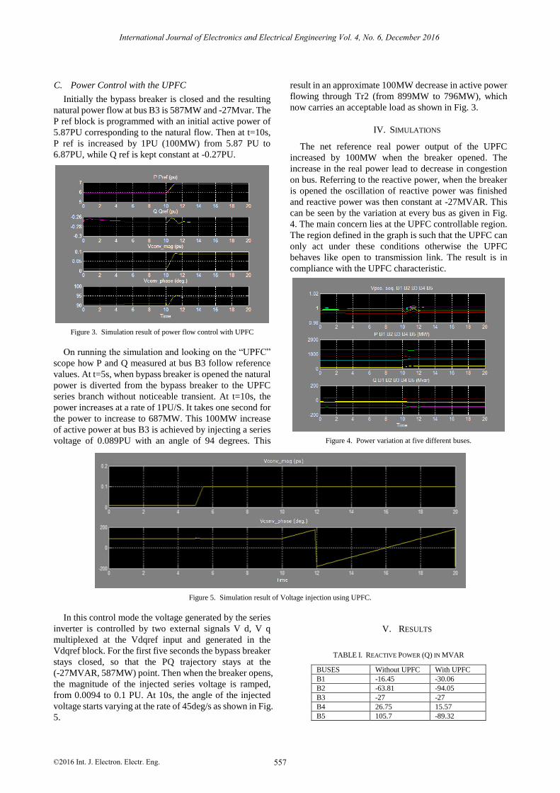
IV. SIMULATIONS
The net reference real power output of the UPFC
increased by 100MW when the breaker opened. The
increase in the real power lead to decrease in congestion
on bus. Referring to the reactive power, when the breaker
is opened the oscillation of reactive power was finished
and reactive power was then constant at -27MVAR. This
can be seen by the variation at every bus as given in Fig.
4. The main concern lies at the UPFC controllable region.
The region defined in the graph is such that the UPFC can
only act under these conditions otherwise the UPFC
behaves like open to transmission link. The result is in
compliance with the UPFC characteristic.
Figure 4. Power variation at five different buses.
Figure 5. Simulation result of Voltage injection using UPFC.
In this control mode the voltage generated by the series
inverter is controlled by two external signals V d, V q
multiplexed at the Vdqref input and generated in the
Vdqref block. For the first five seconds the bypass breaker
stays closed, so that the PQ trajectory stays at the
(-27MVAR, 587MW) point. Then when the breaker opens,
the magnitude of the injected series voltage is ramped,
from 0.0094 to 0.1 PU. At 10s, the angle of the injected
voltage starts varying at the rate of 45deg/s as shown in Fig.
5.
V. RESULTS
TABLE I. REACTIVE POWER (Q) IN MVAR
BUSES Without UPFC With UPFC
B1 -16.45 -30.06
B2 -63.81 -94.05
B3 -27 -27
B4 26.75 15.57
B5 105.7 -89.32
International Journal of Electronics and Electrical Engineering Vol. 4, No. 6, December 2016
©2016 Int. J. Electron. Electr. Eng. 557
TABLE II. ACTIVE POWER (P) IN MW
BUSES Without UPFC With UPFC
B1 95.35 196.6
B2 589 689.7
B3 587 687
B4 898.5 796
B5 1279 1277
TABLE III. VOLTAGE MAGNITUDE
BUSES Without UPFC With UPFC
B1 0.9966 0.9967
B2 0.9994 1.002
B3 0.9996 1.001
B4 0.9926 0.9942
B5 0.9978 0.9989
VI. CONCLUSION
In this paper, a power flow analysis was carried out
using MATLAB. FACTS devices improves the power
transfer capability, control the power flow and reduces the
losses in the power system. The effect of UPFC was
demonstrated. With the presence of UPFC the total power
losses will be reduced in power system transmission, it is
desirable to maintain the voltage magnitude, magnitude,
phase angle and line impedance. So to control the power
flow in the system the concept of power flow and voltage
injection is applied. Modelling the system and studying the
result it shows that UPFC are very helpful FACTS
controller when it comes to maintaining power system as it
is clear from Table I-Table III listed in the paper that the
reactive power is decreased, the active power is increased
and the magnitude of voltage on all the buses is increased.
So the following conclusion can be made that power flow
is achieved, congestion is reduced, transient and steady
stability is improved using UPFC.
REFERENCES
[1] L. Gyugyi, C. D. Schauder, S. L. Williams, T. R. Rietman, D. R.
Torgerson, and A. Edris, “The unified power flow controller : A new
approach to power transmission control,” IEEE Trans. on Power
Delivery, vol. 10, no. 2, pp. 1085-1097, April 1995.
[2] L. Gyugyi, “Unified power flow concept for flexible AC
transmission systems,” IEE Proc.-C, vol. 139, no. 4, pp. 323-332,
July 1992.
[3] K. R. Patidar and K. U. Rao, “A control scheme for unified power
flow controller to improve stability of power systems,” presented at
the Ninth National Power Systems Conference, Kanpur, India, Dec.
1996.
[4] K. R. Patidar, Power System Dynamics - Stability and Control,
Singapore: John Wiley and Sons (SEA) Pvt ltd., 1996.
[5] SIMULINK Users Guide, The Math Works Inc., Natick, Mass.,
1993.
[6] N. G. Higorani and L. Gyugyi, Understanding FACTS Devices,
IEEE Press, 2000.
[7] Y. Xia, Y. H. Song, C. C. Liu, and Y. X. Sun, “Available transfer
capability enhancement using FACTS devices,” IEEE Trans. Power
Systems, vol. 18, no. 1, pp. 305-312, 2003.
[8] M. Noroozian and C. W. Taylor, “Benefits of SVC and STATCOM
for electric utility application,” in Proc. IEEE PES Transmission
and Distribution Conference and Exposition, Sept. 2003.
[9] K. S. Verma, S. N. Singh, and H. O. Gupta, “Location of unified
power flow controller for congestion management,” Electric Power
System Research, vol. 58, no. 2, pp. 89-96, July 2001.
[10] D. Povh, R. Mihalic, and I. Papic, “FACTS equipment for load flow
control in high voltage systems,” in Proc. CIGRE Symposium,
Power Electronics in Power Systems, Tokyo, May 1995.
Ms. Shaifali Jain received her M.Tech degree
from Maulana Azad National Institute of
Technology, Bhopal India in 2005. She is
currently working as assistant professor (SR
Scale) in Department of Electrical and
Electronics, ITM University, Gurgaon. She is
having overall teaching experience of 8 years.
Ms. Ragi Jain received her M.Tech degree
from MMEC, Mullana, Ambala in the year 2012.
Her area of interests includes FACTS devices,
control and instrumentation.
International Journal of Electronics and Electrical Engineering Vol. 4, No. 6, December 2016
©2016 Int. J. Electron. Electr. Eng. 558