46

Power Consumption Measurement Techniques
Maximize the Battery Life of Your Internet of Things Device
Jonathan Chang
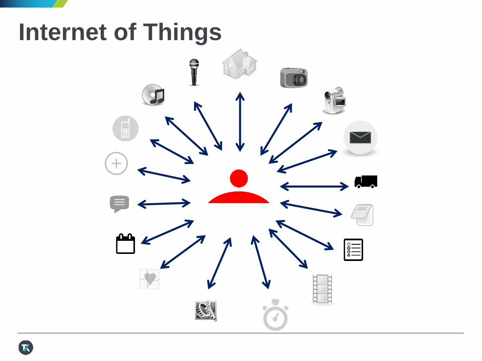
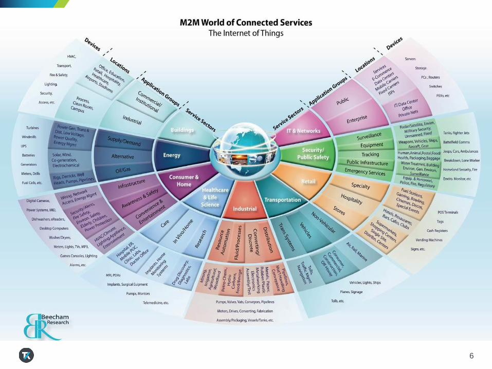
Internet of Things
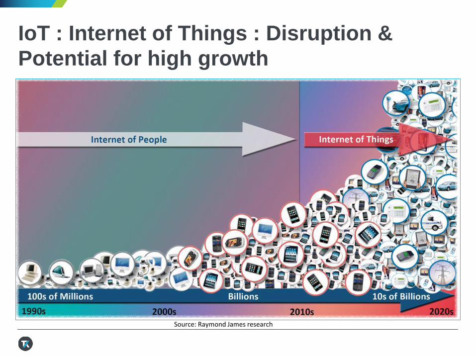
IoT : Internet of Things : Disruption &
Potential for high growth
Source: Raymond James research
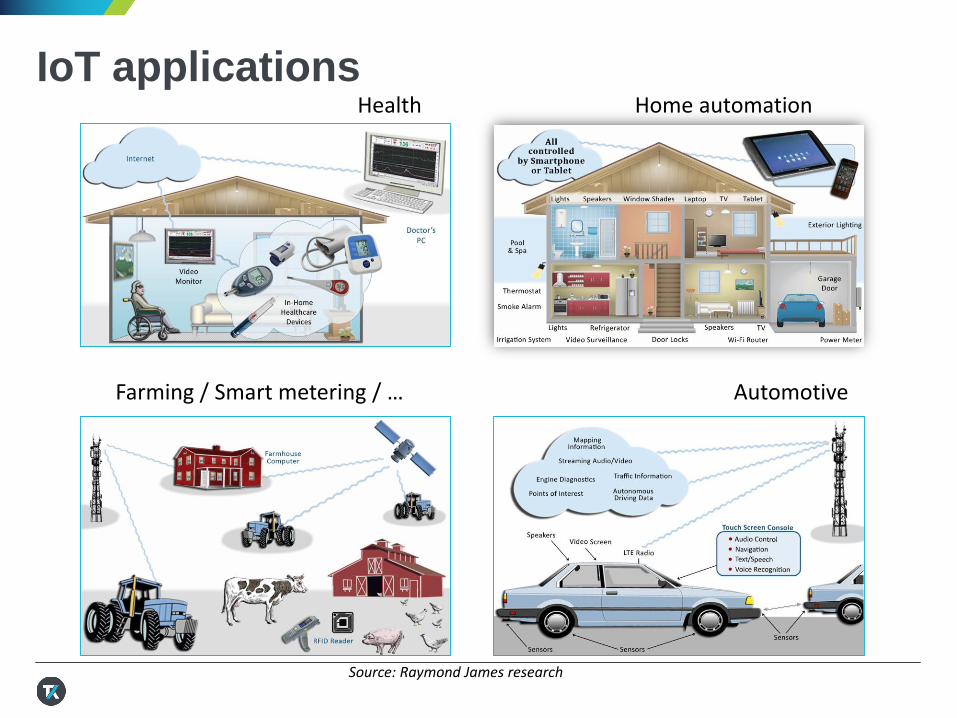
IoT applications
Source: Raymond James research
Health Home automation
Farming / Smart metering / … Automotive
6
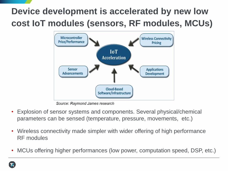
Device development is accelerated by new low
cost IoT modules (sensors, RF modules, MCUs)
• Explosion of sensor systems and components. Several physical/chemical
parameters can be sensed (temperature, pressure, movements, etc.)
• Wireless connectivity made simpler with wider offering of high performance
RF modules
• MCUs offering higher performances (low power, computation speed, DSP, etc.)
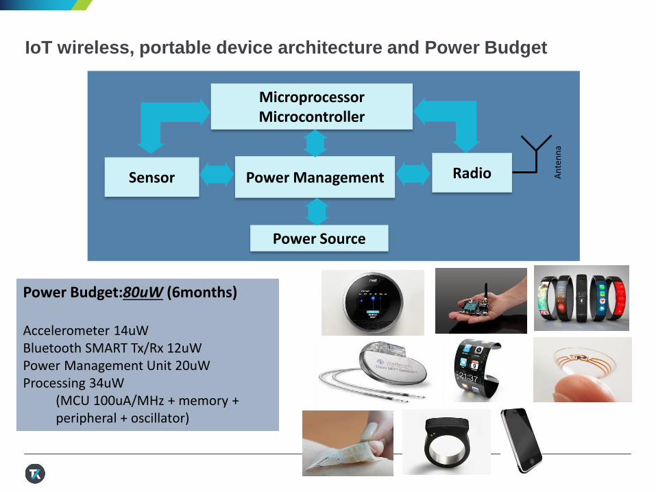
IoT wireless, portable device architecture and Power Budget
Sensor
MicroprocessorMicrocontroller
Power Management Radio
Power Source
An
ten
na
Power Budget:80uW (6months)
Accelerometer 14uW Bluetooth SMART Tx/Rx 12uW Power Management Unit 20uWProcessing 34uW
(MCU 100uA/MHz + memory + peripheral + oscillator)
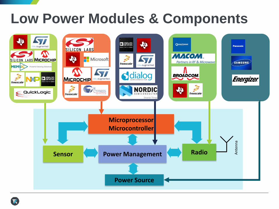
Low Power Modules & Components
Sensor
MicroprocessorMicrocontroller
Power Management Radio
Power Source
An
ten
na
Low Power Devices & End Products
13 MAY 2016
Sensor
MicroprocessorMicrocontroller
Power Management Radio
Power Source
An
ten
na
Enables statistical data analysis
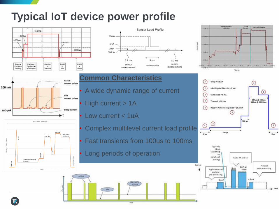
Typical IoT device power profile
Common Characteristics
• A wide dynamic range of current
• High current > 1A
• Low current < 1uA
• Complex multilevel current load profile
• Fast transients from 100us to 100ms
• Long periods of operation
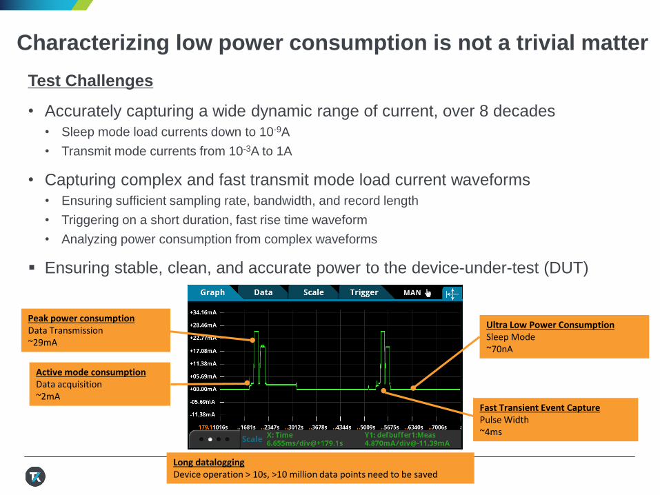
Characterizing low power consumption is not a trivial matter
Test Challenges
• Accurately capturing a wide dynamic range of current, over 8 decades
• Sleep mode load currents down to 10-9A
• Transmit mode currents from 10-3A to 1A
• Capturing complex and fast transmit mode load current waveforms
• Ensuring sufficient sampling rate, bandwidth, and record length
• Triggering on a short duration, fast rise time waveform
• Analyzing power consumption from complex waveforms
Ensuring stable, clean, and accurate power to the device-under-test (DUT)
Active mode consumptionData acquisition~2mA
Ultra Low Power ConsumptionSleep Mode~70nA
Fast Transient Event CapturePulse Width~4ms
Peak power consumptionData Transmission~29mA
Long dataloggingDevice operation > 10s, >10 million data points need to be saved
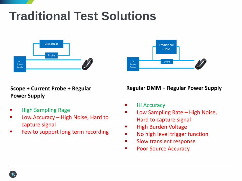
Traditional Test Solutions
Hi Accuracy Low Sampling Rate – High Noise,
Hard to capture signal High Burden Voltage No high level trigger function Slow transient response Poor Source Accuracy
DCPowerSupply
Shunt
Traditional DMM
Regular DMM + Regular Power Supply
DCPowerSupply
Probe
Oscilloscope
High Sampling Rage Low Accuracy – High Noise, Hard to
capture signal Few to support long term recording
Scope + Current Probe + Regular Power Supply
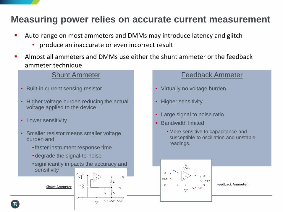
Measuring power relies on accurate current measurement
Shunt Ammeter
• Built-in current sensing resistor
• Higher voltage burden reducing the actual voltage applied to the device
• Lower sensitivity
• Smaller resistor means smaller voltage burden and
• faster instrument response time
• degrade the signal-to-noise
• significantly impacts the accuracy and sensitivity
Feedback Ammeter
• Virtually no voltage burden
• Higher sensitivity
• Large signal to noise ratio
Bandwidth limited
• More sensitive to capacitance and susceptible to oscillation and unstable readings.
Auto-range on most ammeters and DMMs may introduce latency and glitch
• produce an inaccurate or even incorrect result
Almost all ammeters and DMMs use either the shunt ammeter or the feedback ammeter technique
Shunt AmmeterFeedback Ammeter
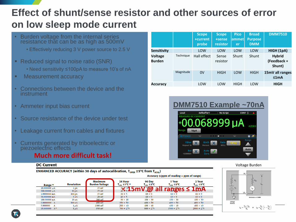
DMM7510 Example ~70nA
Effect of shunt/sense resistor and other sources of error
on low sleep mode current• Burden voltage from the internal series
resistance that can be as high as 500mV
• Effectively reducing 3 V power source to 2.5 V
Reduced signal to noise ratio (SNR)
• Need sensitivity ≤100pA to measure 10’s of nA
Measurement accuracy
• Connections between the device and the instrument
• Ammeter input bias current
• Source resistance of the device under test
• Leakage current from cables and fixtures
• Currents generated by triboelectric or piezoelectric effects
Voltage Burden
Much more difficult task!
Scope +current
probe
Scope +sense resistor
Picoammet
er
Broad Purpose
DMM
DMM7510
Sensitivity LOW LOW LOW LOW HIGH (1pA)
Voltage Burden
Technique Hall effect Sense resistor
Shunt Shunt Hybrid (Feedback +
Shunt)
Magnitude 0V HIGH LOW HIGH 15mV all ranges ≤1mA
Accuracy LOW LOW HIGH LOW HIGH
< 15mV @ all ranges ≤ 1mA

Effect of shunt/sense resistor on high transmit/receive
current
• Burden voltage from the internal series
resistance that can be as high as
500mV
• Effectively reducing 3 V power source to 2.5 V
• Can choose smaller resistance value
with smaller burden voltage and faster
response time and better accuracy
because of the large test signal
Much easier measurement to make!
DMM7510 Example ~ 30mA
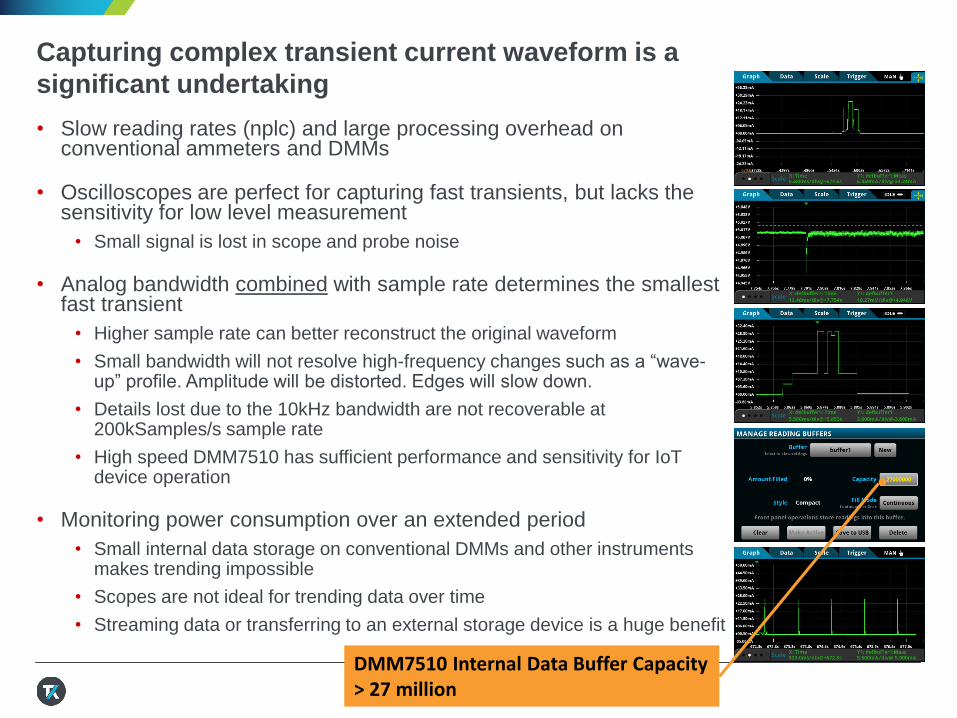
Capturing complex transient current waveform is a
significant undertaking
• Slow reading rates (nplc) and large processing overhead on conventional ammeters and DMMs
• Oscilloscopes are perfect for capturing fast transients, but lacks the sensitivity for low level measurement
• Small signal is lost in scope and probe noise
• Analog bandwidth combined with sample rate determines the smallest fast transient
• Higher sample rate can better reconstruct the original waveform
• Small bandwidth will not resolve high-frequency changes such as a “wave-up” profile. Amplitude will be distorted. Edges will slow down.
• Details lost due to the 10kHz bandwidth are not recoverable at 200kSamples/s sample rate
• High speed DMM7510 has sufficient performance and sensitivity for IoT device operation
• Monitoring power consumption over an extended period
• Small internal data storage on conventional DMMs and other instruments makes trending impossible
• Scopes are not ideal for trending data over time
• Streaming data or transferring to an external storage device is a huge benefit
DMM7510 Internal Data Buffer Capacity > 27 million
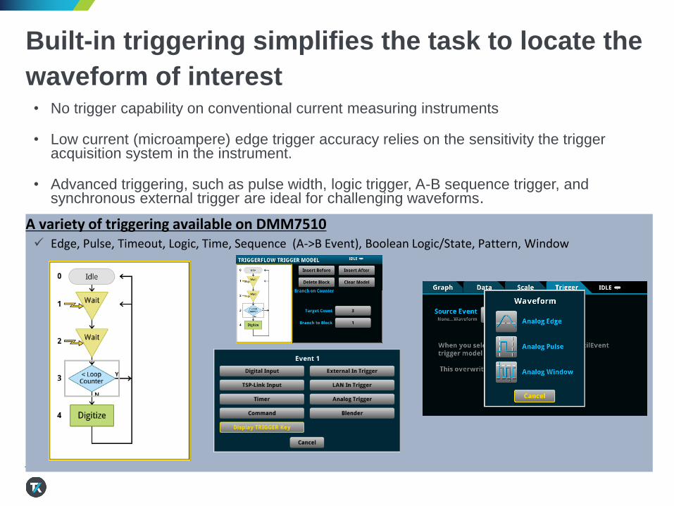
Built-in triggering simplifies the task to locate the
waveform of interest• No trigger capability on conventional current measuring instruments
• Low current (microampere) edge trigger accuracy relies on the sensitivity the trigger acquisition system in the instrument.
• Advanced triggering, such as pulse width, logic trigger, A-B sequence trigger, and synchronous external trigger are ideal for challenging waveforms.
A variety of triggering available on DMM7510 Edge, Pulse, Timeout, Logic, Time, Sequence (A->B Event), Boolean Logic/State, Pattern, Window
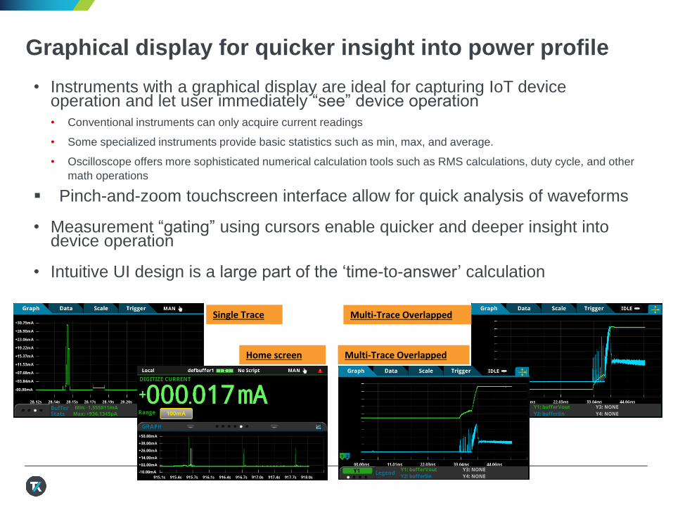
Graphical display for quicker insight into power profile
• Instruments with a graphical display are ideal for capturing IoT device operation and let user immediately “see” device operation • Conventional instruments can only acquire current readings
• Some specialized instruments provide basic statistics such as min, max, and average.
• Oscilloscope offers more sophisticated numerical calculation tools such as RMS calculations, duty cycle, and other
math operations
Pinch-and-zoom touchscreen interface allow for quick analysis of waveforms
• Measurement “gating” using cursors enable quicker and deeper insight into device operation
• Intuitive UI design is a large part of the ‘time-to-answer’ calculation
Single Trace Multi-Trace Overlapped
Home screen Multi-Trace Overlapped
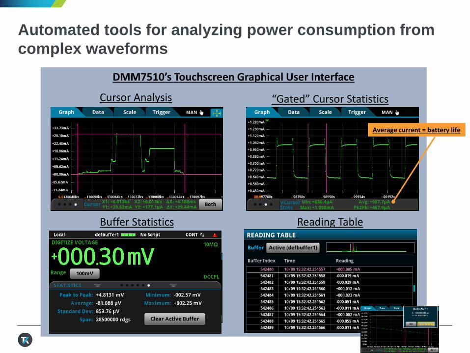
DMM7510’s Touchscreen Graphical User Interface
“Gated” Cursor Statistics
Buffer Statistics
Automated tools for analyzing power consumption from
complex waveforms
Cursor Analysis
Reading Table
Average current = battery life
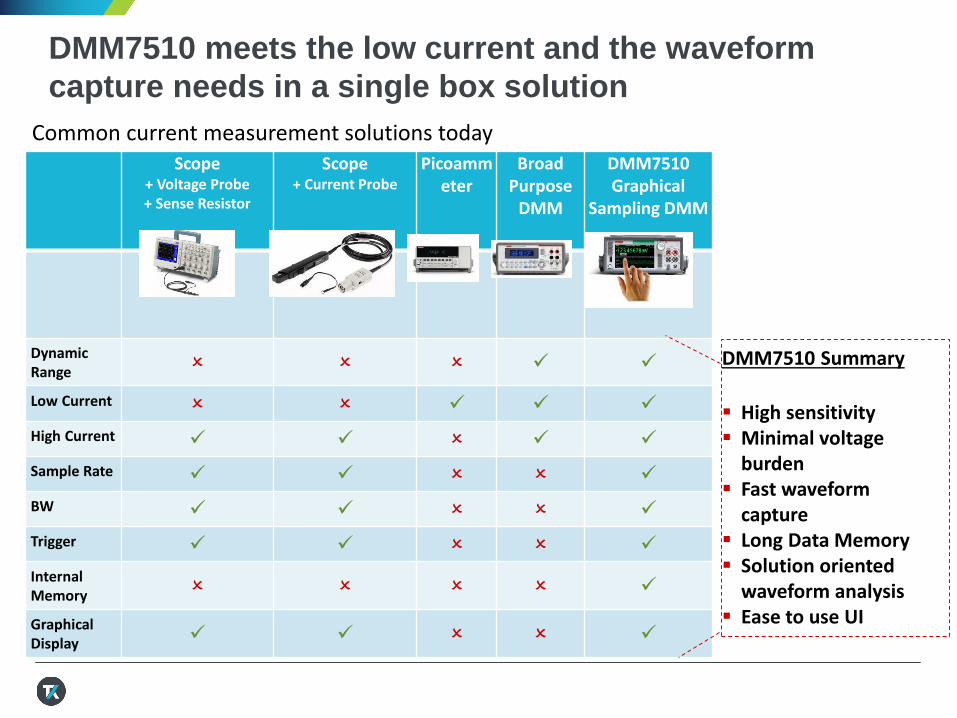
DMM7510 meets the low current and the waveform
capture needs in a single box solution
Scope + Voltage Probe + Sense Resistor
Scope+ Current Probe
Picoammeter
BroadPurpose
DMM
DMM7510Graphical
Sampling DMM
DynamicRange
Low Current
High Current
Sample Rate
BW
Trigger
InternalMemory
GraphicalDisplay
DMM7510 Summary
High sensitivity Minimal voltage
burden Fast waveform
capture Long Data Memory Solution oriented
waveform analysis Ease to use UI
Common current measurement solutions today
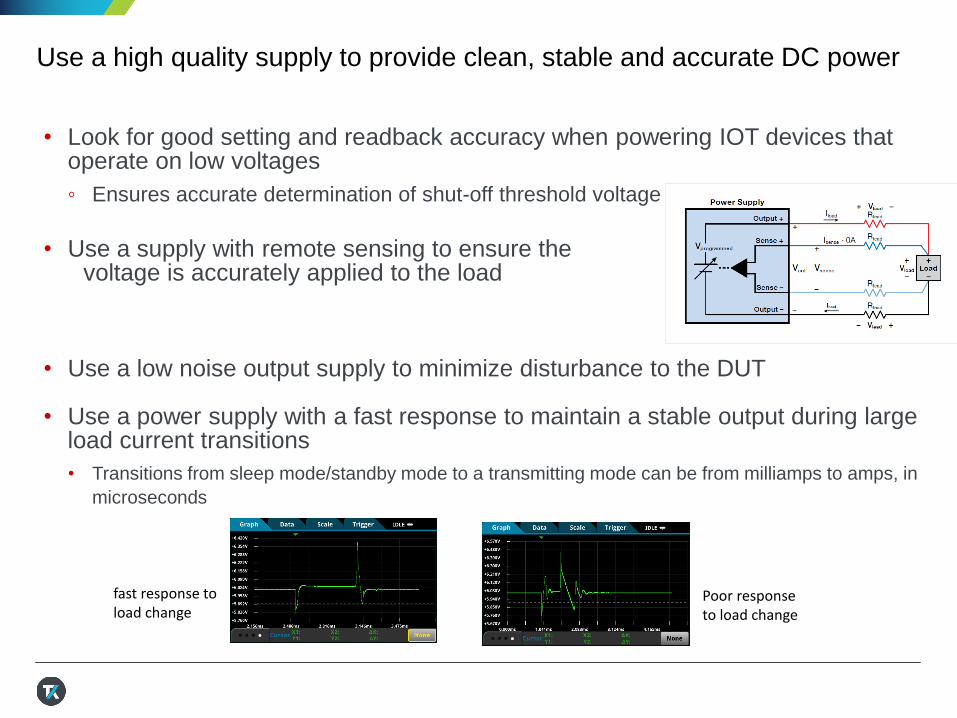
Use a high quality supply to provide clean, stable and accurate DC power
• Look for good setting and readback accuracy when powering IOT devices that operate on low voltages
◦ Ensures accurate determination of shut-off threshold voltage
• Use a supply with remote sensing to ensure the voltage is accurately applied to the load
• Use a low noise output supply to minimize disturbance to the DUT
• Use a power supply with a fast response to maintain a stable output during large load current transitions
• Transitions from sleep mode/standby mode to a transmitting mode can be from milliamps to amps, in
microseconds
fast response to load change
Poor response to load change
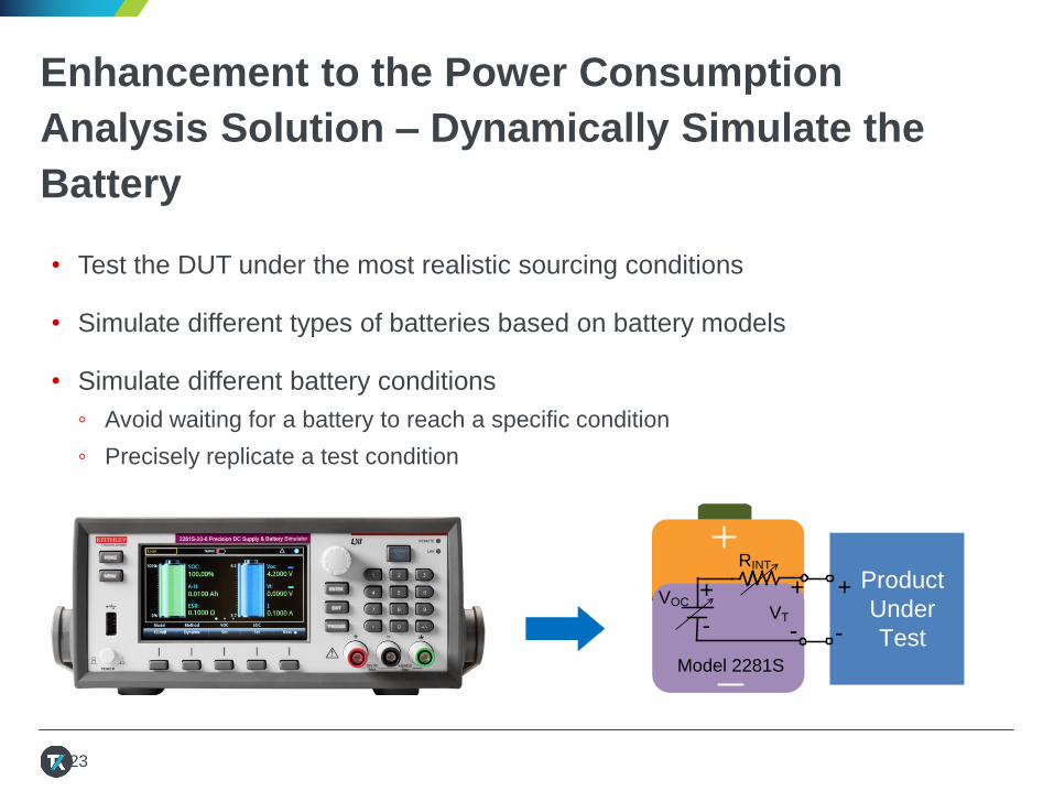
Enhancement to the Power Consumption
Analysis Solution – Dynamically Simulate the
Battery
• Test the DUT under the most realistic sourcing conditions
• Simulate different types of batteries based on battery models
• Simulate different battery conditions
◦ Avoid waiting for a battery to reach a specific condition
◦ Precisely replicate a test condition
23
VOCVT
++
- -
Product
Under
Test
+
-
RINT
Model 2281S
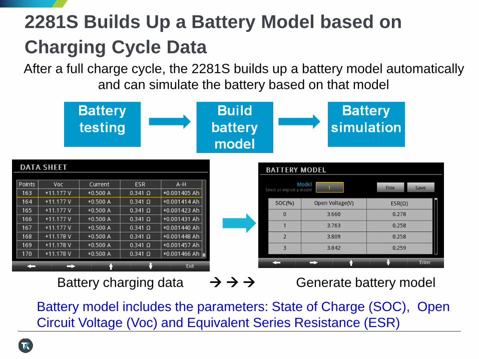
2281S Builds Up a Battery Model based on
Charging Cycle DataAfter a full charge cycle, the 2281S builds up a battery model automatically
and can simulate the battery based on that model
Battery model includes the parameters: State of Charge (SOC), Open
Circuit Voltage (Voc) and Equivalent Series Resistance (ESR)
Battery charging data Generate battery model
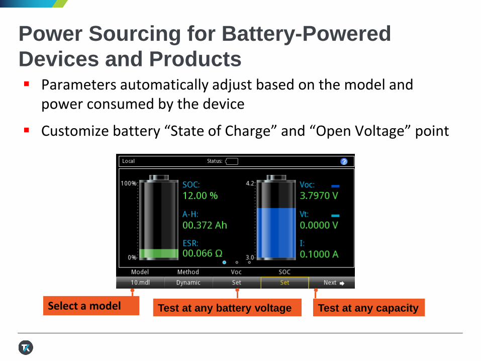
Power Sourcing for Battery-Powered
Devices and Products Parameters automatically adjust based on the model and
power consumed by the device
Customize battery “State of Charge” and “Open Voltage” point
Select a model Test at any battery voltage Test at any capacity
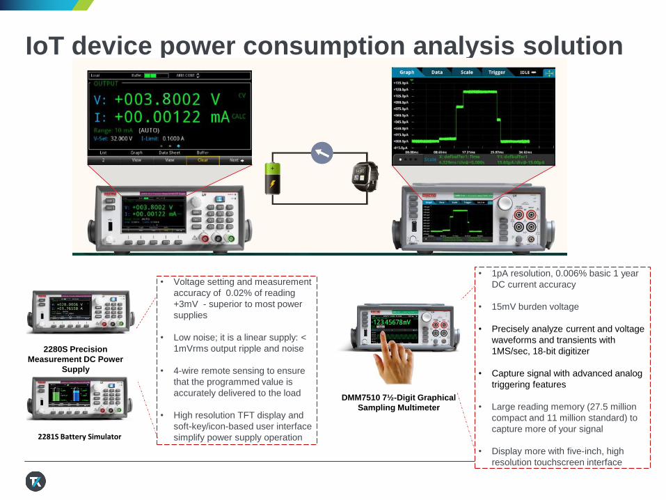
IoT device power consumption analysis solution
• Voltage setting and measurement
accuracy of 0.02% of reading
+3mV - superior to most power
supplies
• Low noise; it is a linear supply: <
1mVrms output ripple and noise
• 4-wire remote sensing to ensure
that the programmed value is
accurately delivered to the load
• High resolution TFT display and
soft-key/icon-based user interface
simplify power supply operation
2280S Precision
Measurement DC Power
Supply
DMM7510 7½ -Digit Graphical
Sampling Multimeter
• 1pA resolution, 0.006% basic 1 year
DC current accuracy
• 15mV burden voltage
• Precisely analyze current and voltage
waveforms and transients with
1MS/sec, 18-bit digitizer
• Capture signal with advanced analog
triggering features
• Large reading memory (27.5 million
compact and 11 million standard) to
capture more of your signal
• Display more with five-inch, high
resolution touchscreen interface
2281S Battery Simulator
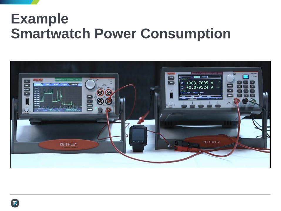
ExampleSmartwatch Power Consumption
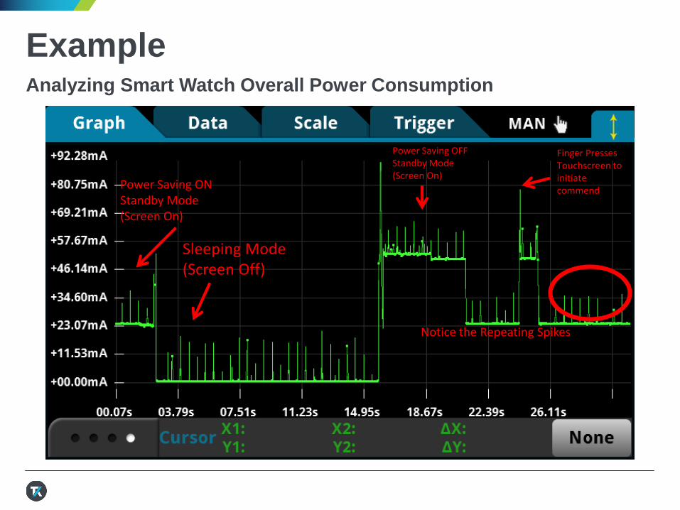
ExampleAnalyzing Smart Watch Overall Power Consumption
Sleeping Mode (Screen Off)
Power Saving ON Standby Mode(Screen On)
Power Saving OFFStandby Mode(Screen On)
Finger Presses Touchscreen to initiate commend
Notice the Repeating Spikes
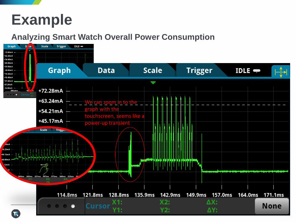
ExampleAnalyzing Smart Watch Overall Power Consumption
We can zoom in to the graph with the touchscreen, seems like a power-up transient
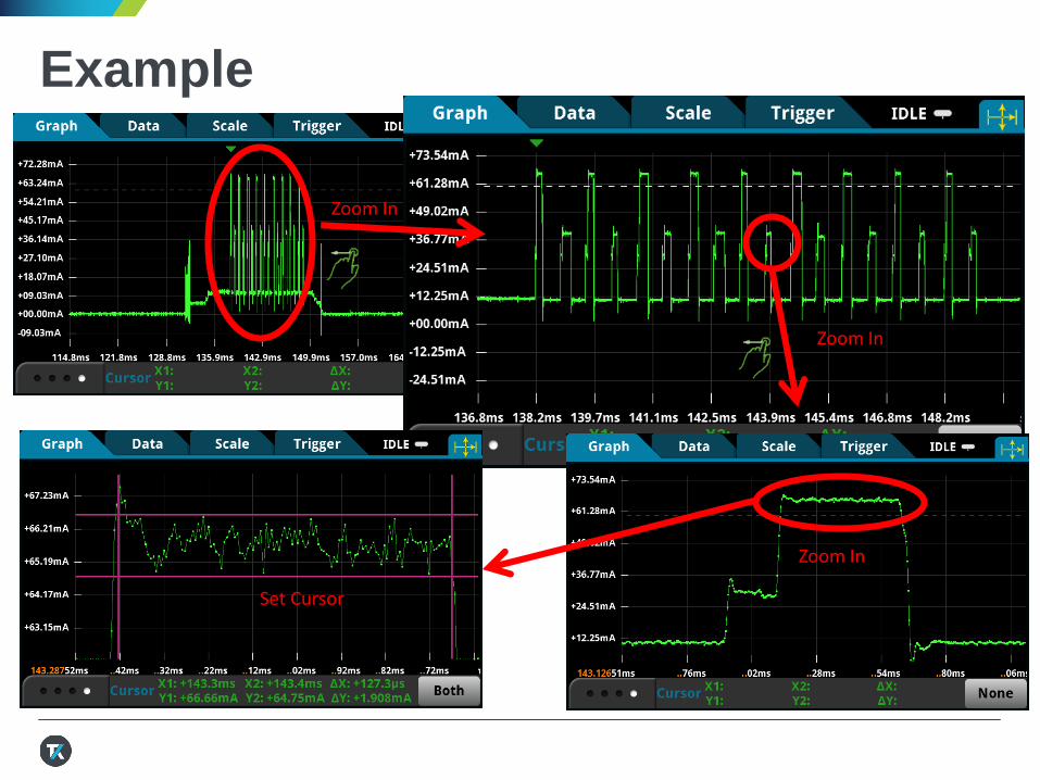
ExampleAnalyzing Smart Watch Overall Power Consumption
Zoom In
Zoom In
Zoom In
Set Cursor
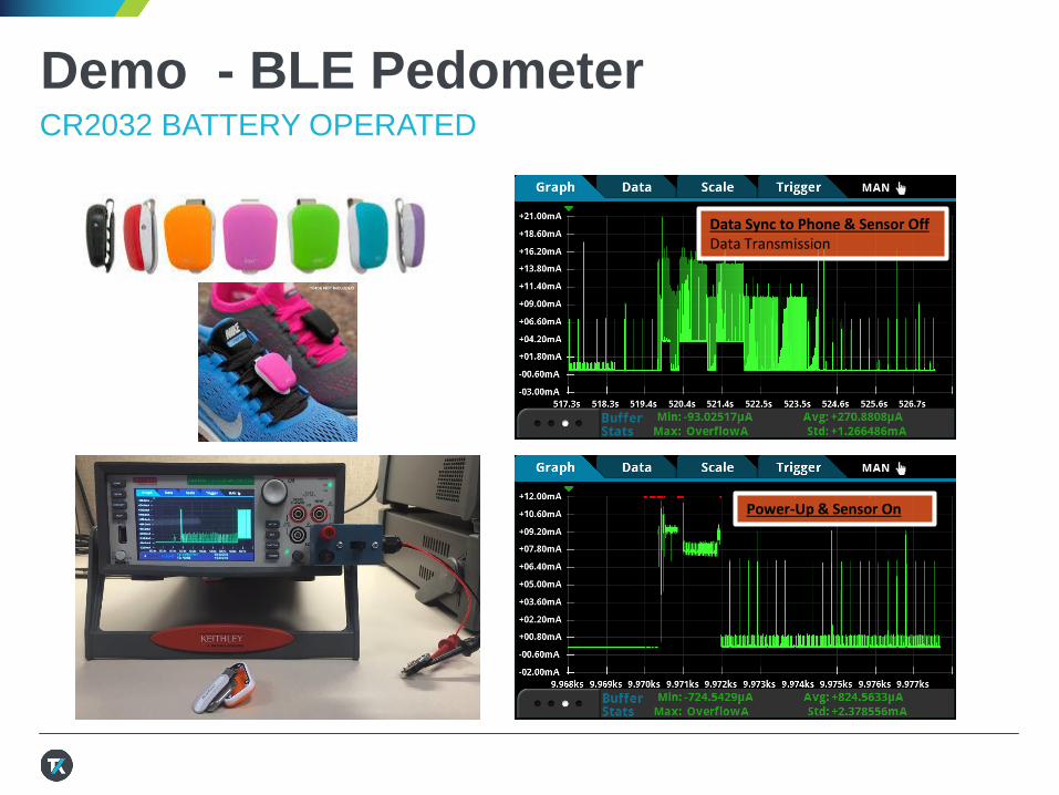
Demo - BLE PedometerCR2032 BATTERY OPERATED
Data Sync to Phone & Sensor OffData Transmission
Power-Up & Sensor On
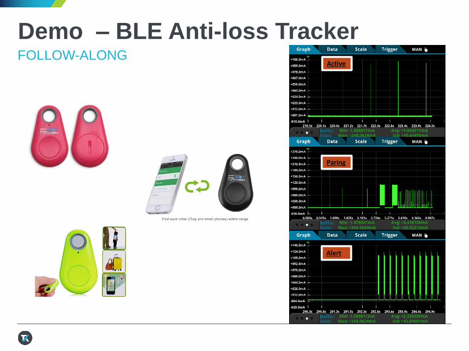
Demo – BLE Anti-loss TrackerFOLLOW-ALONG
Paring
Active
Alert
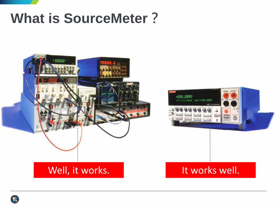
What is SourceMeter?
Well, it works. It works well.
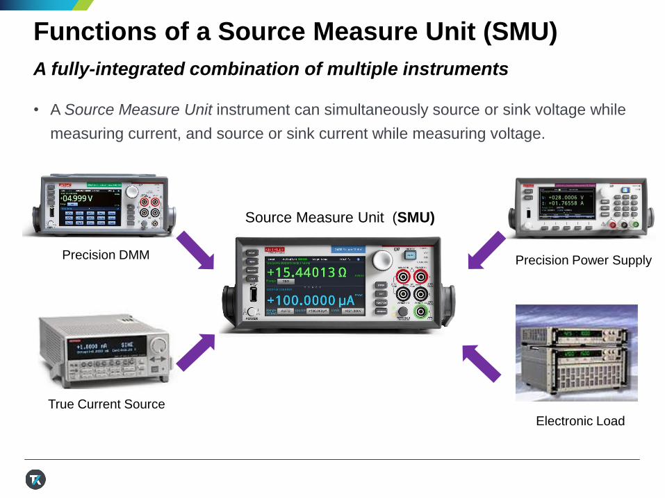
Functions of a Source Measure Unit (SMU)
A fully-integrated combination of multiple instruments
• A Source Measure Unit instrument can simultaneously source or sink voltage while
measuring current, and source or sink current while measuring voltage.
True Current Source
Precision Power Supply
Source Measure Unit (SMU)
Precision DMM
Electronic Load
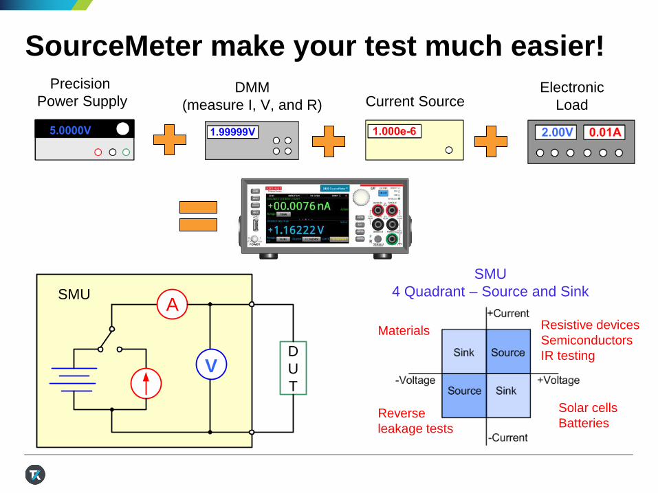
SourceMeter make your test much easier!Precision
Power SupplyDMM
(measure I, V, and R) Current SourceElectronic
Load
SMU
4 Quadrant – Source and Sink
Resistive devices
Semiconductors
IR testing
Solar cells
BatteriesReverse
leakage tests
Materials
A
V
SMU
D
U
T
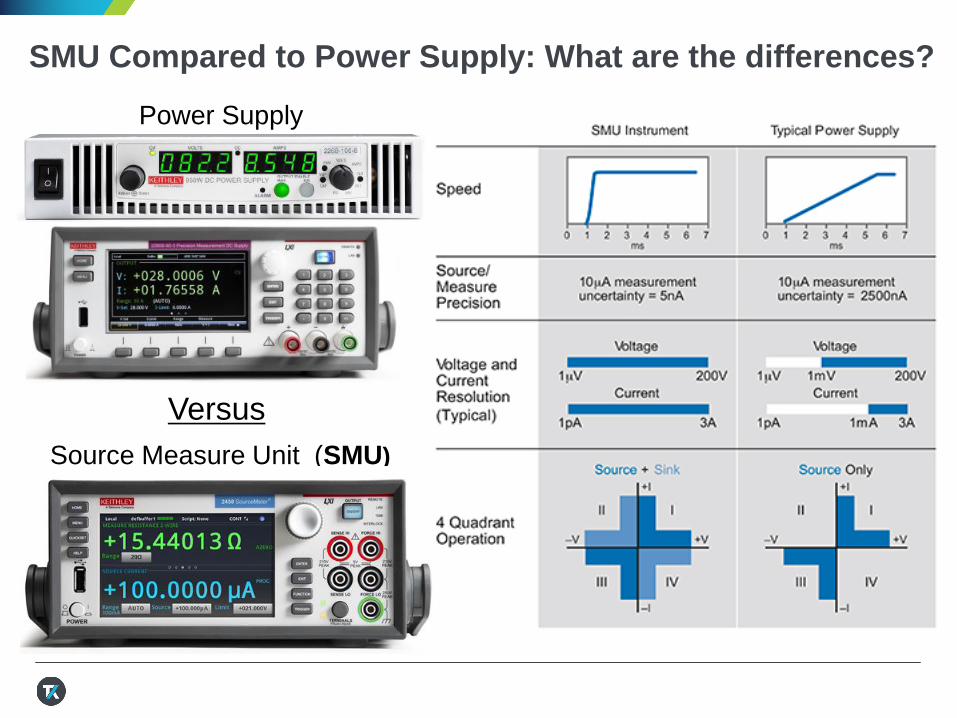
SMU Compared to Power Supply: What are the differences?
Source Measure Unit (SMU)
Power Supply
Versus
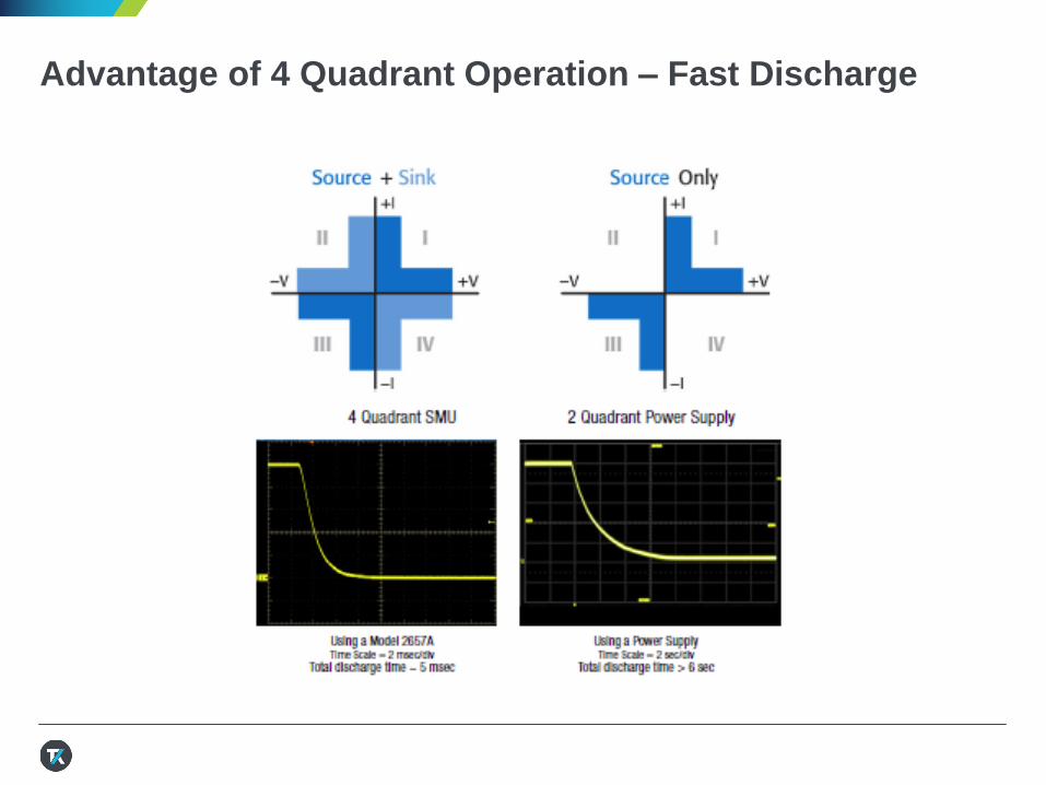
Advantage of 4 Quadrant Operation – Fast Discharge
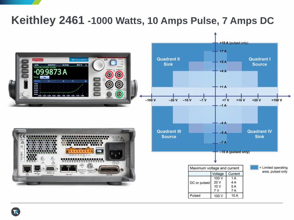
Keithley 2461 -1000 Watts, 10 Amps Pulse, 7 Amps DC
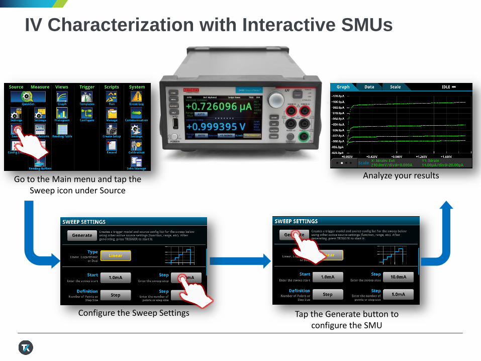
IV Characterization with Interactive SMUs
Go to the Main menu and tap the Sweep icon under Source
Configure the Sweep Settings Tap the Generate button to configure the SMU
Analyze your results
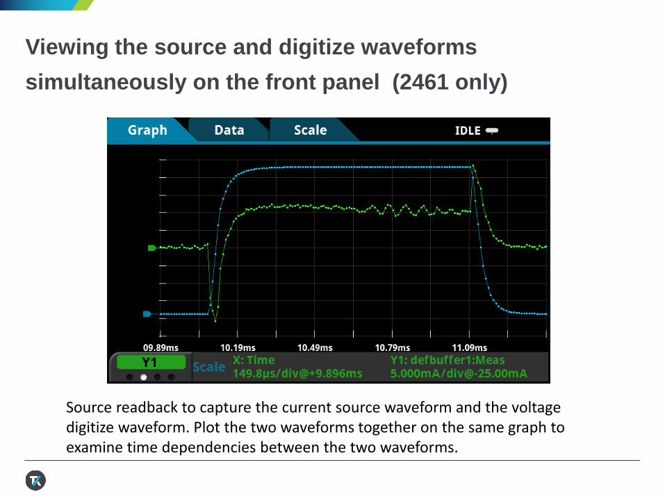
Viewing the source and digitize waveforms
simultaneously on the front panel (2461 only)
Source readback to capture the current source waveform and the voltagedigitize waveform. Plot the two waveforms together on the same graph to examine time dependencies between the two waveforms.
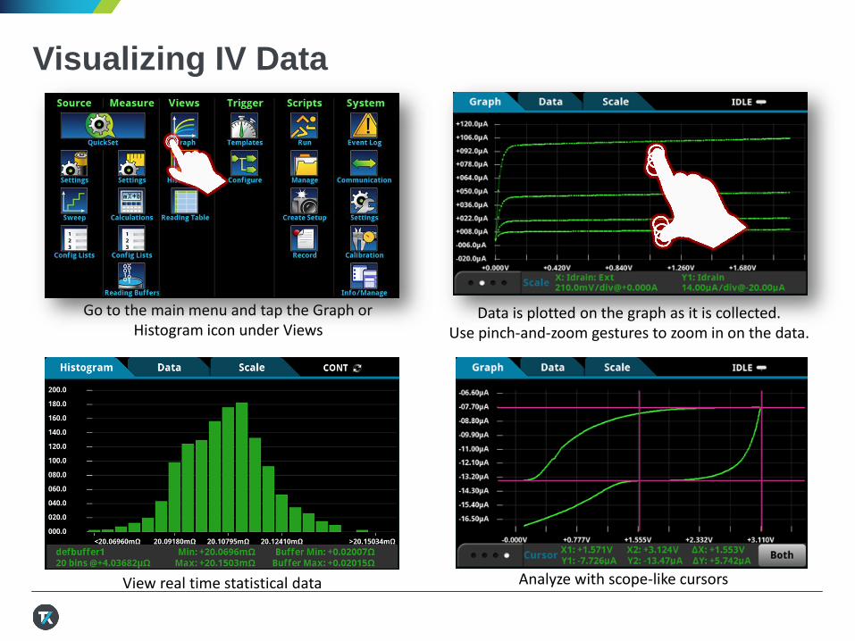
Visualizing IV Data
Go to the main menu and tap the Graph or Histogram icon under Views
Data is plotted on the graph as it is collected.Use pinch-and-zoom gestures to zoom in on the data.
View real time statistical data Analyze with scope-like cursors

Saving the Data
Go to the Main menu and tap the Data Buffers icon under Measure
Tap the name of the buffer where the sweep data was collected, defbuffer1
Tap the Save to USB button Give the file a name then tap OK
1. 2. 2.
3. 4.
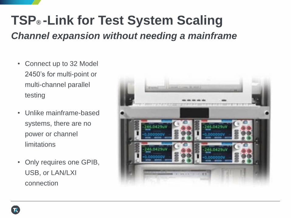
TSP® -Link for Test System ScalingChannel expansion without needing a mainframe
• Connect up to 32 Model
2450’s for multi-point or
multi-channel parallel
testing
• Unlike mainframe-based
systems, there are no
power or channel
limitations
• Only requires one GPIB,
USB, or LAN/LXI
connection
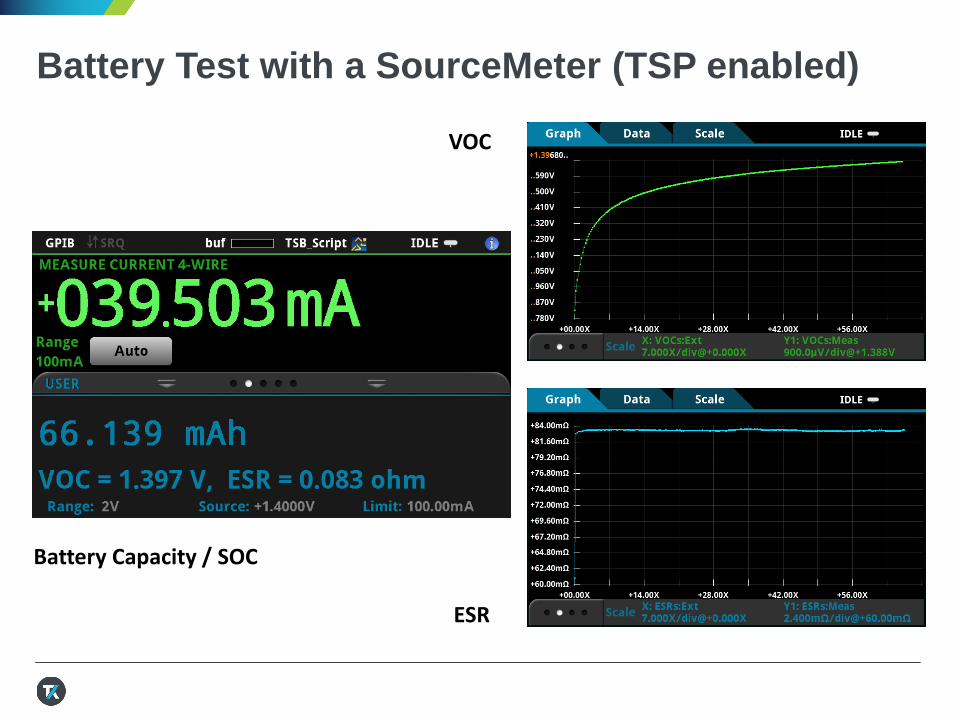
Battery Test with a SourceMeter (TSP enabled)
VOC
ESR
Battery Capacity / SOC
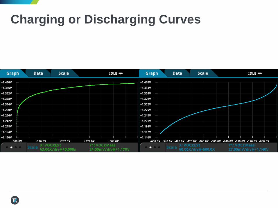
Charging or Discharging Curves

Thank You !


