Power Electronic Capacitors PEC MKP DC Series/Type: MKP DC (Resin Top) Ordering code: B25690 Date: Aug. 2019 Version: 1 TDK Electronics AG 2019. Reproduction, publication and dissemination of this publication, enclosures hereto and the information contained therein without TDK Electronics' prior express consent is prohibited. Content of header bars 1 and 2 of data sheet will be automatically entered in headers and footers! Please fill in the table and then change the color to "white". This ensures that the table disappears (invisible) for the customer PDF. Don't change formatting when entering or pasting text in the table and don't add any cell or line in and to it! Identification/Classification 1 (header 1 + top left bar): Power Electronic Capacitors Identification/Classification 2 (header 2 + bottom left header bar): PEC MKP DC Ordering code: (top right header bar) B25690 Series/Type: (bottom right header bar) MKP DC (Resin Top) Preliminary data (optional): Department: CAP PW PD Date: Aug. 2019 Version: 1
Transcript
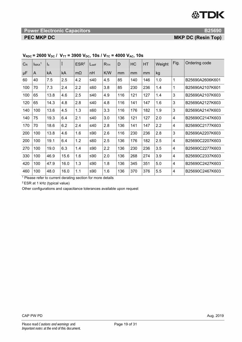
Power Electronic Capacitors
PEC MKP DC
Series/Type: MKP DC (Resin Top) Ordering code: B25690
Date: Aug. 2019 Version: 1
TDK Electronics AG 2019. Reproduction, publication and dissemination of this publication, enclosures hereto and the information contained therein without TDK Electronics' prior express consent is prohibited.
Content of header bars 1 and 2 of data sheet will be automatically entered in headers and footers! Please fill in the table and then change the color to "white". This ensures that the table disappears (invisible) for the customer PDF. Don't change formatting when entering or pasting text in the table and don't add any cell or line in and to it! Identification/Classification 1 (header 1 + top left bar):
Power Electronic Capacitors
Identification/Classification 2 (header 2 + bottom left header bar):
PEC MKP DC
Ordering code: (top right header bar) B25690 Series/Type: (bottom right header bar) MKP DC (Resin Top) Preliminary data (optional): Department: CAP PW PD Date: Aug. 2019 Version: 1
Power Electronic Capacitors B25690
PEC MKP DC MKP DC (Resin Top)
CAP PW PD Aug. 2019
Please read Cautions and warnings and Page 2 of 31 Important notes at the end of this document.
1. Construction and general data
Characteristics Standard capacitance tolerance K: ±10%
Dielectric dissipation factor (tan δo) 2 • 10-4
Service life expectancy tLD (co) (refer to section 3)
100 000 h at Ths +75 °C and VRDC for D≤116 mm 100 000 h at Ths +70 °C and VRDC for D=136 mm up to 200 000 h (considering de-ratings in voltage and/or temperature)
Expected failure rate αFQ (co) 50 fit at VRDC and +70 °C (refer to section 4)
Minimum temperature Top,min. –40 °C
Maximum temperature Top,max. +85 °C for diameter 75 ≤ ØD ≤100 mm +75 °C for diameter 116≤ ØD ≤136 mm
Storage temperature Tstg –40 ... +85 °C
Maximum hotspot temperature Ths (refer to section 1)
+85 °C for diameter 75 ≤ ØD ≤100 mm +75 °C for diameter 116≤ ØD ≤136 mm
Climatic category 40/85/56 for 75 ≤ ØD ≤100 mm diameter 40/75/56 for 116≤ ØD ≤136 mm diameter
Maximum altitude 2 000 m above sea level (derating curves available upon request)
Partial discharge extinction voltage (typical) >1.6 kVac (10 pC) (higher value upon request)
Test data
Voltage test between terminals VTT 1.5 VRDC, 10 s
Voltage test between terminals and case VTC (√2VRDC + 1 000) V AC or 4 000 V AC whichever is the highest value, 10 s
Design data
Resin filling Non PCB, hard polyurethane (dry type)
Mounting and grounding M12 threaded bolt on bottom of the aluminum case
Distance between terminals: 1 = 32 mm 3 = 50 mm 9 = special
Capacitance tolerance J = ± 5% K = ± 10% A = special
Internal use code
Power Electronic Capacitors B25690
PEC MKP DC MKP DC (Resin Top)
CAP PW PD Aug. 2019
Please read Cautions and warnings and Page 4 of 31 Important notes at the end of this document.
1.3 Standard types
Distance between terminals (mm)
OC ending
Diameter (Ø)
Terminal type
32 ± 0.5
-**1
50 ± 0.5
-**3
75/85 mm Female M6 standard
100 mm Female M6 standard
116/136 mm Female M6 standard
Other terminal configurations available upon request.
1.4 Drawings
Figure 1: - B25690A – ØD=75/85 mm Figure 2: - B25690A – ØD=100 mm
- Female terminals (M6) - Female terminals (M6)
- Between terminals 32 ±0.5 mm - Between terminals 32 ±0.5 mm
Power Electronic Capacitors B25690
PEC MKP DC MKP DC (Resin Top)
CAP PW PD Aug. 2019
Please read Cautions and warnings and Page 5 of 31 Important notes at the end of this document.
Figure 3: - B25690A - ØD=116 mm Figure 4: - B25690C - ØD=136 mm
- Female terminals (M6) - Female terminals (M6)
- Between terminals 50 ±0.5 mm - Between terminals 50 ±0.5 mm
Power Electronic Capacitors B25690
PEC MKP DC MKP DC (Resin Top)
CAP PW PD Aug. 2019
Please read Cautions and warnings and Page 6 of 31 Important notes at the end of this document.
Terms and characteristics
The following definitions apply to power capacitors according to IEC 61071.
Rated capacitance CR Nominal value of the capacitance at 20 °C and measuring frequency of 100 Hz. Rated DC voltage VRDC Maximum operating peak voltage of either polarity but of a non-reversing type wave form, for which the
capacitor has been designed, for continuous operation. Ripple voltage Vripple Peak-to-peak alternating component of the unidirectional voltage.
This value must not exceed 0.28 ∙ VRDC
Maximum surge voltage Vs Peak voltage induced by a switching or any other disturbance of the system which is allowed for a limited
number of times and short period.
Insulation voltage Vi Rms rated value of the insulation voltage of capacitive elements and terminals to case or earth. When it is not
specified in the product data sheet, the insulation voltage is at least:
Vi = 2
VRDC
AC voltage test between terminals and case VTC Units having all terminals insulated from the container shall be subjected for 10 s to a voltage applied between the terminals (joined together) and the container. Maximum rate of voltage rise (dv/dt)max
Maximum permissible repetitive rate of voltage rise of the operational voltage.
Maximum current Imax
Maximum rms current for continuous operation for the given frequency range and for the maximum ripple
voltage. Please provide Frequency Spectrum of rms current to your sales contact.
Maximum peak current Î Maximum permissible repetitive current amplitude during continuous operation.
Maximum peak current (Î) and maximum rate of voltage rise (dV/dt)max on a capacitor are related as follows:
Î = C ∙ (dv/dt)max Maximum surge current Î s
Admissible peak current induced by a switching or any other disturbance of the system which is allowed for a
limited number of times and short period.
Îs = C ∙ (dv/dt)s
Ambient temperature TA
Temperature of the surrounding air, measured at 10 cm distance and 2/3 of the case height of the capacitor.
Power Electronic Capacitors B25690
PEC MKP DC MKP DC (Resin Top)
CAP PW PD Aug. 2019
Please read Cautions and warnings and Page 7 of 31 Important notes at the end of this document.
Lowest operating temperature Top,min
Lowest permitted ambient temperature at which a capacitor may be energized.
Maximum operating temperature Top,max
Highest permitted capacitor temperature during operation, i.e. temperature at the hottest point of the case.
Hot-spot temperature Ths
Temperature zone inside of the capacitor at hottest spot.
Ths =TA+ IRMS2 ∙ ESR ∙ Rth
Tangent of the loss angle of a capacitor tan
Ratio between the equivalent series resistance and the capacitive reactance of a capacitor at a specified
sinusoidal alternating voltage, frequency and temperature.
Series resistance Rs
The sum of all Ohmic resistances occurring inside the capacitor.
ESR Effective resistance which, if connected in series with an ideal capacitor of capacitance value equal to that of the capacitor in question, would have a power loss equal to active power dissipated in that capacitor under specified operating conditions.
ESR = Ctan
= C
Rs
0tan
Thermal resistance Rth
The thermal resistance indicates by how many degrees the capacitor temperature at the hot spot rises in
relation to the dissipation losses.
Maximum power loss Pmax
Maximum permissible power dissipation for the capacitor’s operation.
Pmax = thR
Ahs T T
Self inductance Lself
The sum of all inductive elements which are contained in a capacitor.
Resonance frequency fr
The lowest frequency at which the impedance of the capacitor becomes minimum.
fr = Rself CL2
1
Power Electronic Capacitors B25690
PEC MKP DC MKP DC (Resin Top)
CAP PW PD Aug. 2019
Please read Cautions and warnings and Page 8 of 31 Important notes at the end of this document.
Please read Cautions and warnings and Page 26 of 31 Important notes at the end of this document.
3. Service life expectancy
Service life tLD at different hotspot temperature (hs) and voltage V
For capacitors with diameter 116mm a maximum hot spot temperature of 85°C or capacitor with diameter 136mm a maximum hot spot temperature of 80°C is allowed during short term operation (maximum 10% of the total load duration) without further reduction of the service life.
The expected lifetime is a calculated value based on real application data and life endurance test for this capacitor series. The lifetime calculation correlates the time of test, voltage and temperature always comparing testing conditions to real application data and its own ageing factors. In order to determine the ageing factor used for this capacitor design it was performed life endurance tests with different stress is voltage and temperature.
Failure criteria is capacitance drop higher than 3%.
0,9
0,95
1
1,05
1,1
0,0 0,2 0,4 0,6 0,8 1,0 1,2 1,4 1,6 1,8 2,0
VO
P/
VR
DC
tLD / tLD(co)
Expected L i fe t ime @ T HS
70℃ 75℃ 80℃ 85℃
Power Electronic Capacitors B25690
PEC MKP DC MKP DC (Resin Top)
CAP PW PD Aug. 2019
Please read Cautions and warnings and Page 27 of 31 Important notes at the end of this document.
4. Expected failure rate
The FIT (Failure In Time) of a component is defined as the number of expected failures in 109 hours of operation. The FIT rate is calculated on the basis of the number of components operating in the field and the estimated hours of operation. All the reports of failures are taken into consideration for this calculation, which is updated every year. The other values in the graph are given as indication and calculated based on acceleration factors.
1
10
100
1000
0,7 0,8 0,9 1 1,1 1,2
FIT
Voltage x Un
FIT Rate - PEC MKP DC
Ths: 60°C 65°C 70°C 75°C 80°C 85°C
Power Electronic Capacitors B25690
PEC MKP DC MKP DC (Resin Top)
CAP PW PD Aug. 2019
Please read Cautions and warnings and Page 28 of 31 Important notes at the end of this document.
Cautions and warnings
In case of dents of more than 1 mm depth or any other mechanical damage, capacitors must not be used at all.
Check tightness of the connections/terminals periodically.
The energy stored in capacitors may be lethal. To prevent any chance of shock, discharge and short-circuit the capacitor before handling.
Failure to follow cautions may result, worst case, in premature failures, bursting and fire.
Protect the capacitor properly against over current and short circuit.
TDK Electronics is not responsible for any kind of possible damages to persons or things due to improper installation and application of capacitors for power electronics.
Safety
Electrical or mechanical misapplication of capacitors may be hazardous. Personal injury or property damage may result from bursting of the capacitor or from expulsion melted material due to mechanical disruption of the capacitor.
Ensure good, effective grounding for capacitor enclosures.
Observe appropriate safety precautions during operation (self-recharging phenomena and the high energy contained in capacitors).
Handle capacitors carefully, because they may still be charged even after disconnection.
The terminals of capacitors, connected bus bars and cables as well as other devices may also be energized.
Follow good engineering practice.
Thermal load
After installation of the capacitor it is necessary to verify that maximum hot-spot temperature is not exceeded at extreme service conditions.
Mechanical protection
The capacitor has to be installed in a way that mechanical damages and dents in the aluminum can are avoided.
Storage and operating conditions
Do not use or store capacitors in corrosive atmosphere, especially where chloride gas, sulfide gas, acid, alkali, salt or the like are present. In dusty environments regular maintenance and cleaning especially of the terminals is required to avoid conductive path between phases and/or phases and ground.
Power Electronic Capacitors B25690
PEC MKP DC MKP DC (Resin Top)
CAP PW PD Aug. 2019
Please read Cautions and warnings and Page 29 of 31 Important notes at the end of this document.
Service life expectancy
Electrical components do not have an unlimited service life expectancy; this applies to self-healing capacitors, too. The maximum service life expectancy may vary depending on the application the capacitor is used in.
Display of ordering codes for TDK Electronics products
The ordering code for one and the same TDK Electronics product can be represented differently in data sheets, data books, other publications, on the TDK Electronics website, or in order-related documents such as shipping notes, order confirmations and product labels. The varying representations of the ordering codes are due to different processes employed and do not affect the specifications of the respective products. Detailed information can be found on the Internet under www.tdk-electronics.tdk.com.
Important notes
Page 30 of 31
The following applies to all products named in this publication:
1. Some parts of this publication contain statements about the suitability of our products for certain areas of application. These statements are based on our knowledge of typical requirements that are often placed on our products in the areas of application concerned. We nevertheless expressly point out that such statements cannot be regarded as binding statements about the suitability of our products for a particular customer application. As a rule we are either unfamiliar with individual customer applications or less familiar with them than the customers themselves. For these reasons, it is always ultimately incumbent on the customer to check and decide whether a product with the properties described in the product specification is suitable for use in a particular customer application.
2. We also point out that in individual cases, a malfunction of electronic components or failure before the end of their usual service life cannot be completely ruled out in the current state of the art, even if they are operated as specified. In customer applications requiring a very high level of operational safety and especially in customer applications in which the malfunction or failure of an electronic component could endanger human life or health (e.g. in accident prevention or life-saving systems), it must therefore be ensured by means of suitable design of the customer application or other action taken by the customer (e.g. installation of protective circuitry or redundancy) that no injury or damage is sustained by third parties in the event of malfunction or failure of an electronic component.
3. The warnings, cautions and product-specific notes must be observed.
4. In order to satisfy certain technical requirements, some of the products described in this publication may contain substances subject to restrictions in certain jurisdictions (e.g. because they are classed as hazardous). Useful information on this will be found in our Material Data Sheets on the Internet (www.tdk-electronics.tdk.com/material). Should you have any more detailed questions, please contact our sales offices.
5. We constantly strive to improve our products. Consequently, the products described in this publication may change from time to time. The same is true of the corresponding product specifications. Please check therefore to what extent product descriptions and specifications contained in this publication are still applicable before or when you place an order.
We also reserve the right to discontinue production and delivery of products. Consequently, we cannot guarantee that all products named in this publication will always be available. The aforementioned does not apply in the case of individual agreements deviating from the foregoing for customer-specific products.
6. Unless otherwise agreed in individual contracts, all orders are subject to our General Terms and Conditions of Supply.
7. Our manufacturing sites serving the automotive business apply the IATF 16949 standard. The IATF certifications confirm our compliance with requirements regarding the quality management system in the automotive industry. Referring to customer requirements and customer specific requirements (“CSR”) TDK always has and will continue to have the policy of respecting individual agreements. Even if IATF 16949 may appear to support the acceptance of unilateral requirements, we hereby like to emphasize that only requirements mutually agreed upon can and will be implemented in our Quality Management System. For clarification purposes we like to point out that obligations from IATF 16949 shall only become legally binding if individually agreed upon.
Important notes
Page 31 of 31
8. The trade names EPCOS, CeraCharge, CeraDiode, CeraLink, CeraPad, CeraPlas, CSMP, CTVS, DeltaCap, DigiSiMic, ExoCore, FilterCap, FormFit, LeaXield, MiniBlue, MiniCell, MKD, MKK, MotorCap, PCC, PhaseCap, PhaseCube, PhaseMod, PhiCap, PowerHap, PQSine, PQvar, SIFERRIT, SIFI, SIKOREL, SilverCap, SIMDAD, SiMic, SIMID, SineFormer, SIOV, ThermoFuse, WindCap are trademarks registered or pending in Europe and in other countries. Further information will be found on the Internet at www.tdk-electronics.tdk.com/trademarks.