Page 1
ELECTRICAL DRIVES: ELECTRICAL DRIVES: An Application of Power ElectronicsAn Application of Power Electronics
Dr. Nik Rumzi Nik Idris,Dr. Nik Rumzi Nik Idris,(Senior Member IEEE)(Senior Member IEEE)
Department of Energy Conversion,Department of Energy Conversion,Universiti Teknologi MalaysiaUniversiti Teknologi Malaysia
Skudai, JOHORSkudai, JOHOR
Page 2
CONTENTSCONTENTS
Power Electronic SystemsPower Electronic Systems
Modern Electrical Drive Systems Modern Electrical Drive Systems
Power Electronic Converters in Electrical DrivesPower Electronic Converters in Electrical Drives:: DC and AC Drives:: DC and AC Drives
Modeling and Control of Electrical DrivesModeling and Control of Electrical Drives
:: Current controlled Converters :: Current controlled Converters :: Modeling of Power Converters :: Modeling of Power Converters :: Scalar control of IM:: Scalar control of IM
Page 3
Power Electronic Systems
What is Power Electronics ?
A field of Electrical Engineering that deals with the application of power semiconductor devices for the control and conversion of electric power
Power ElectronicsConverters
Power ElectronicsConverters
LoadLoad
ControllerController
Output- AC- DC
InputSource- AC- DC- unregulated
Reference
POWER ELECTRONIC CONVERTERS – the heart of power a power electronics system
sensors
Page 4
Power Electronic Systems
Why Power Electronics ?
Power semiconductor devices Power switches
ON or OFF+ vsw − = 0
isw
+ vsw −
isw = 0
Ploss = vsw× isw = 0
Losses ideally ZERO !
Page 5
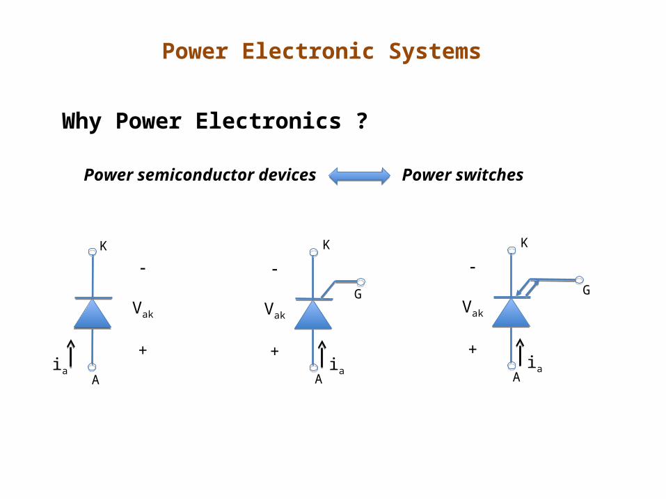
Power Electronic Systems
Why Power Electronics ?
Power semiconductor devices Power switches
Vak
+ia
G
K
A
Vak
+ia
K
A
Vak
+ia
G
K
A
Page 6
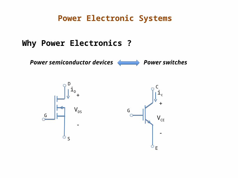
Power Electronic Systems
Why Power Electronics ?
Power semiconductor devices Power switches
D
S
G
+
VDS
iD
G
C
E
+
VCE
ic
Page 7
Power Electronic Systems
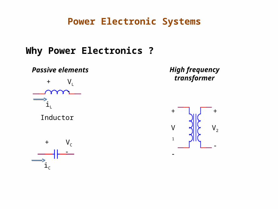
Why Power Electronics ?
Passive elements High frequencytransformer
+
V1
+
V2
Inductor
+ VL
iL
+ VC
iC
Page 8
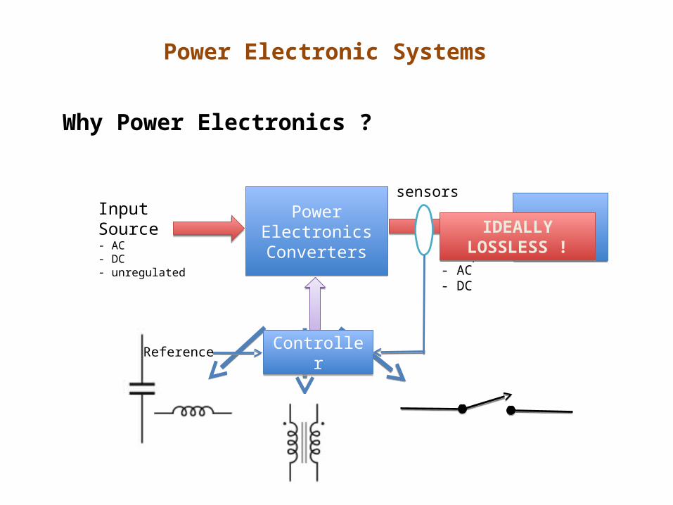
Power Electronic Systems
Why Power Electronics ?
Power ElectronicsConverters
Power ElectronicsConverters
sensors
LoadLoad
ControllerController
Output- AC- DC
InputSource- AC- DC- unregulated
Reference
IDEALLY LOSSLESS !IDEALLY LOSSLESS !
Page 9
Power Electronic Systems
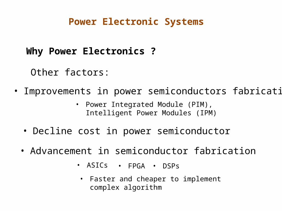
Why Power Electronics ?
Other factors:
• Improvements in power semiconductors fabrication
• Decline cost in power semiconductor
• Advancement in semiconductor fabrication• ASICs • FPGA • DSPs
• Faster and cheaper to implement complex algorithm
• Power Integrated Module (PIM), Intelligent Power Modules (IPM)
Page 10
Power Electronic Systems
Some Applications of Power Electronics :
Power rating of < 1 W (portable equipment)
Tens or hundreds Watts (Power supplies for computers /office equipment)
Typically used in systems requiring efficient control and conversion of electric energy:
Domestic and Commercial ApplicationsIndustrial ApplicationsTelecommunicationsTransportationGeneration, Transmission and Distribution of electrical energy
kW to MW : drives
Hundreds of MW in DC transmission system (HVDC)
Page 11
Modern Electrical Drive Systems
• About 50% of electrical energy used for drives
• Can be either used for fixed speed or variable speed
• 75% - constant speed, 25% variable speed (expanding)
• Variable speed drives typically used PEC to supply the motors
AC motors - IM- PMSM
DC motors (brushed)
SRMBLDC
Page 12
Modern Electrical Drive Systems
Classic Electrical Drive for Variable Speed Application :
• Bulky
• Inefficient
• inflexible
Page 13
Modern Electrical Drive Systems
PowerElectronicConverters
PowerElectronicConverters
LoadLoadMotor
Motor
ControllerControllerReference
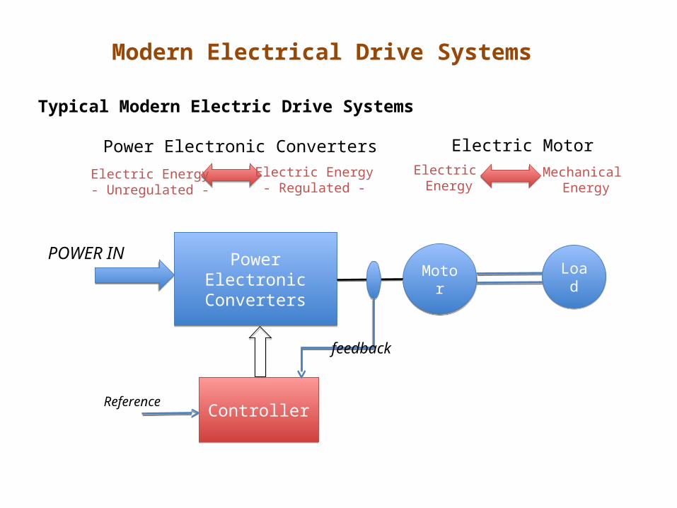
POWER IN
feedback
Typical Modern Electric Drive Systems
Power Electronic Converters
Electric Energy- Unregulated -
Electric Energy- Regulated -
Electric MotorElectric Energy
Mechanical Energy
Page 14
Modern Electrical Drive Systems
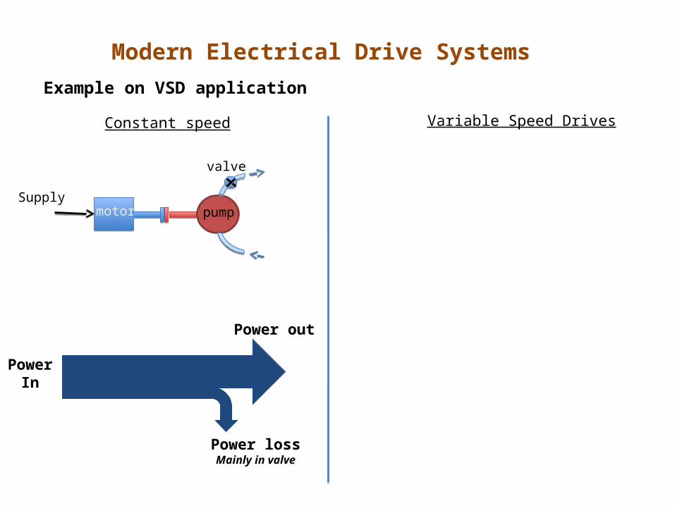
Example on VSD application
motor pump
valve
Supply
Constant speed Variable Speed Drives
PowerIn
Power lossMainly in valve
Power out
Page 15
Modern Electrical Drive Systems
Example on VSD application
PowerIn
Power lossMainly in valve
Power out
motor pump
valve
SupplymotorPEC pump
Supply
Constant speed Variable Speed Drives
PowerIn
Power loss
Power out
Page 16
Modern Electrical Drive Systems
PowerIn
Power lossMainly in valve
Power out
PowerIn
Power loss
Power out
motor pump
valve
SupplymotorPEC pump
Supply
Constant speed Variable Speed Drives
Example on VSD application
Page 17
Modern Electrical Drive Systems
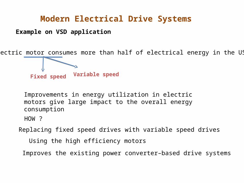
Electric motor consumes more than half of electrical energy in the US
Fixed speed Variable speed
HOW ?
Improvements in energy utilization in electric motors give large impact to the overall energy consumption
Replacing fixed speed drives with variable speed drives
Using the high efficiency motors
Improves the existing power converter–based drive systems
Example on VSD application
Page 18
DC drives: Electrical drives that use DC motors as the prime mover
Regular maintenance, heavy, expensive, speed limit
AC drives: Electrical drives that use AC motors as the prime mover
Less maintenance, light, less expensive, high speed
Modern Electrical Drive Systems
Overview of AC and DC drives
Easy control, decouple control of torque and flux
Coupling between torque and flux – variable spatial angle between rotor and stator flux
Page 19
Before semiconductor devices were introduced (<1950)• AC motors for fixed speed applications• DC motors for variable speed applications
After semiconductor devices were introduced (1960s)
• Variable frequency sources available – AC motors in variable speed applications
• Coupling between flux and torque control• Application limited to medium performance applications –
fans, blowers, compressors – scalar control
• High performance applications dominated by DC motors – tractions, elevators, servos, etc
Modern Electrical Drive Systems
Overview of AC and DC drives
Page 20
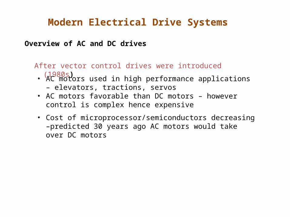
After vector control drives were introduced (1980s)
• AC motors used in high performance applications – elevators, tractions, servos
• AC motors favorable than DC motors – however control is complex hence expensive
• Cost of microprocessor/semiconductors decreasing –predicted 30 years ago AC motors would take over DC motors
Modern Electrical Drive Systems
Overview of AC and DC drives
Page 21
Overview of AC and DC drives
Extracted from Boldea & Nasar
Modern Electrical Drive Systems
Page 22
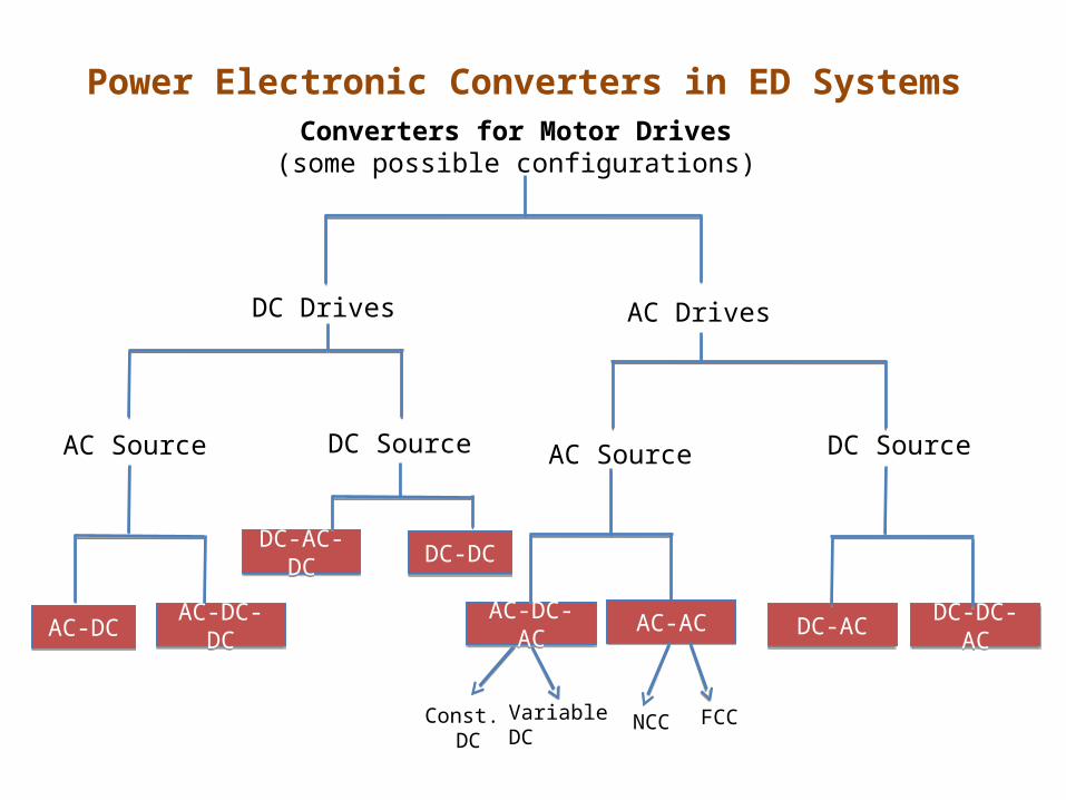
Power Electronic Converters in ED SystemsConverters for Motor Drives(some possible configurations)
DC Drives AC Drives
DC SourceAC Source
AC-DC-DCAC-DC-DCAC-DCAC-DC
AC Source
Const. DC
Variable DC
AC-DC-ACAC-DC-AC AC-ACAC-AC
NCC FCC
DC Source
DC-ACDC-AC DC-DC-ACDC-DC-AC
DC-DCDC-DCDC-AC-DCDC-AC-DC
Page 23
Power Electronic Converters in ED Systems
Converters for Motor Drives
Configurations of Power Electronic Converters depend on:
Sources available
Type of Motors
Drive Performance - applications
- Braking
- Response
- Ratings
Page 24
Power Electronic Converters in ED SystemsDC DRIVES
Available AC source to control DC motor (brushed)
AC-DC-DCAC-DC-DCAC-DCAC-DC
Controlled Rectifier Single-phase Three-phase
Uncontrolled Rectifier Single-phase Three-phase
DC-DC Switched mode 1-quadrant, 2-quadrant 4-quadrant
Control Control
Page 25
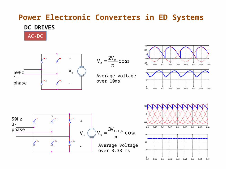
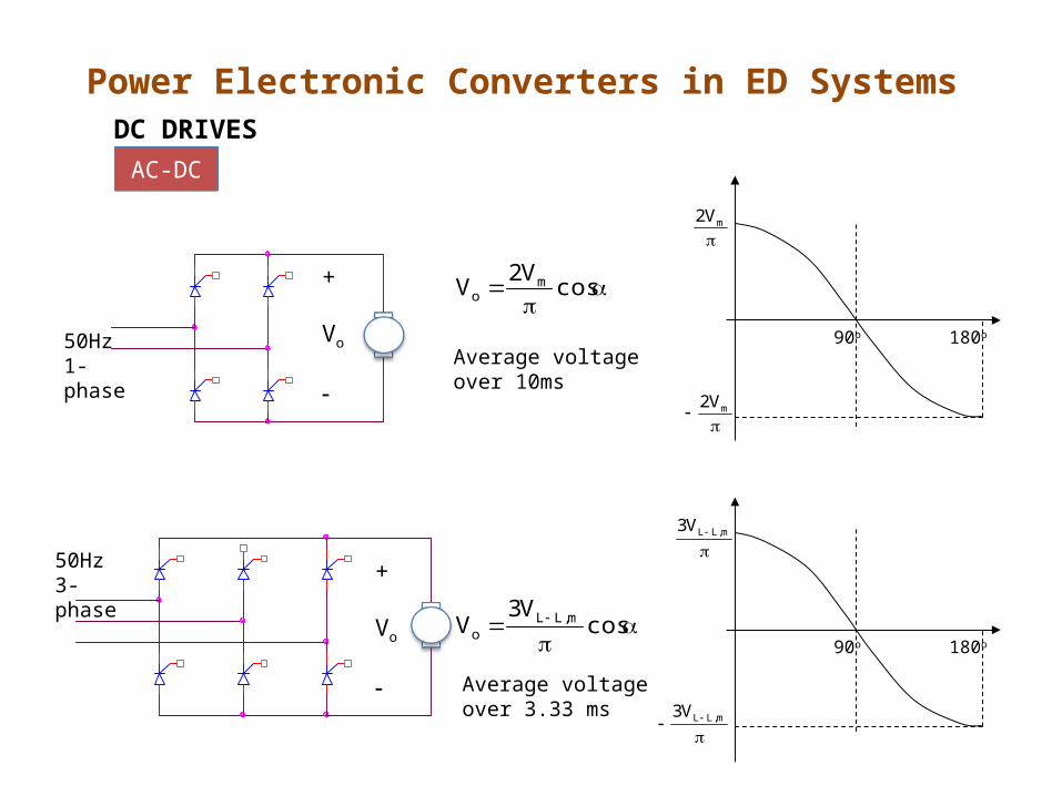
Power Electronic Converters in ED SystemsDC DRIVES
+
Vo
+
Vo
cosV2
V mo
cosV3
V m,LLo
Average voltage over 10ms
Average voltage over 3.33 ms
50Hz1-phase
50Hz3-phase
AC-DCAC-DC
0.4 0.405 0.41 0.415 0.42 0.425 0.43 0.435 0.44-400
-200
0
200
400
0.4 0.405 0.41 0.415 0.42 0.425 0.43 0.435 0.440
5
10
0.4 0.405 0.41 0.415 0.42 0.425 0.43 0.435 0.44
-500
0
500
0.4 0.405 0.41 0.415 0.42 0.425 0.43 0.435 0.440
10
20
30
Page 26
Power Electronic Converters in ED SystemsDC DRIVES
+
Vo
+
Vo
cosV2
V mo
90o 180o
mV2
mV2
90o
m,LLV3
m,LLV3
cosV3
V m,LLo
Average voltage over 10ms
Average voltage over 3.33 ms
50Hz1-phase
50Hz3-phase
180o
AC-DCAC-DC
Page 27
Power Electronic Converters in ED SystemsDC DRIVES
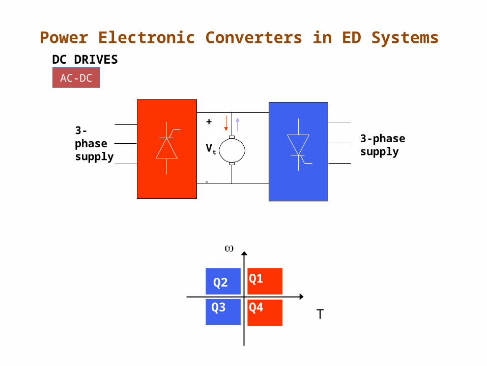
AC-DCAC-DC
Ia
Q1Q2
Q3 Q4
Vt
3-phasesupply
+
Vt
ia
- Operation in quadrant 1 and 4 only
Page 28
Power Electronic Converters in ED SystemsDC DRIVES
AC-DCAC-DC
Q1Q2
Q3 Q4
T
3-phasesupply
3-phasesupply
+
Vt
Page 29
Power Electronic Converters in ED SystemsDC DRIVES
AC-DCAC-DC
Q1Q2
Q3 Q4
T
F1
F2
R1
R2+ Va -
3-phasesupply
Page 30
Power Electronic Converters in ED SystemsDC DRIVES
AC-DCAC-DC
Cascade control structure with armature reversal (4-quadrant):
Speedcontroller
Speedcontroller
CurrentController
CurrentController
FiringCircuitFiringCircuit
Armature reversal
Armature reversal
iD
iD,ref
iD,ref
iD,
ref + +
__
Page 31
Power Electronic Converters in ED SystemsDC DRIVES
AC-DC-DCAC-DC-DC
controlUncontrolled rectifier
Switch Mode DC-DC1-Quadrant2-Quadrant4-Quadrant
Page 32
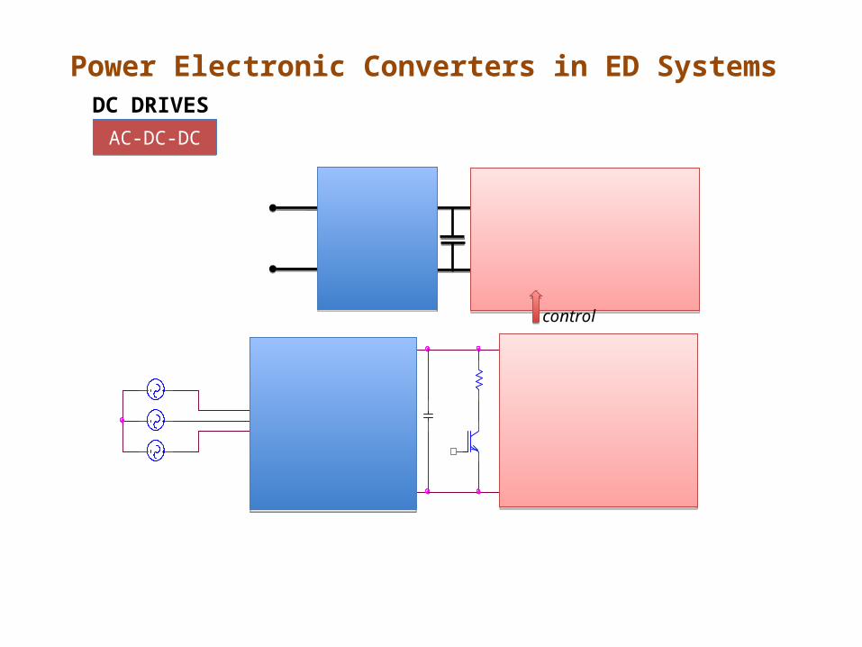
Power Electronic Converters in ED SystemsDC DRIVES
AC-DC-DCAC-DC-DC
control
Page 33
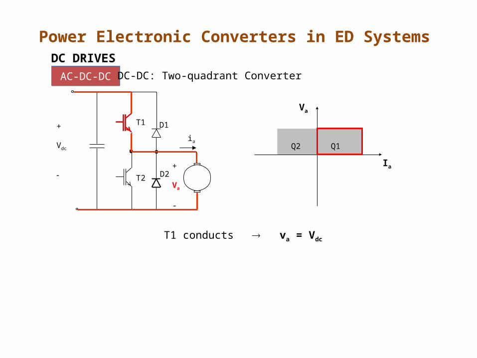
T1 conducts va = Vdc
Q1Q2
Va
Ia
T1
T2
D1
+
Va
-
D2
ia
+
Vdc
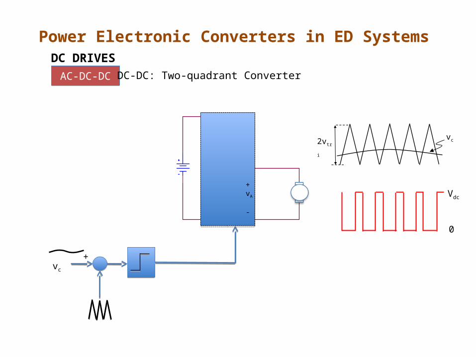
DC DRIVES
AC-DC-DCAC-DC-DC DC-DC: Two-quadrant Converter
Power Electronic Converters in ED Systems
Page 34
Q1Q2
Va
Ia
T1
T2
D1
+
Va
-
D2
ia
+
Vdc
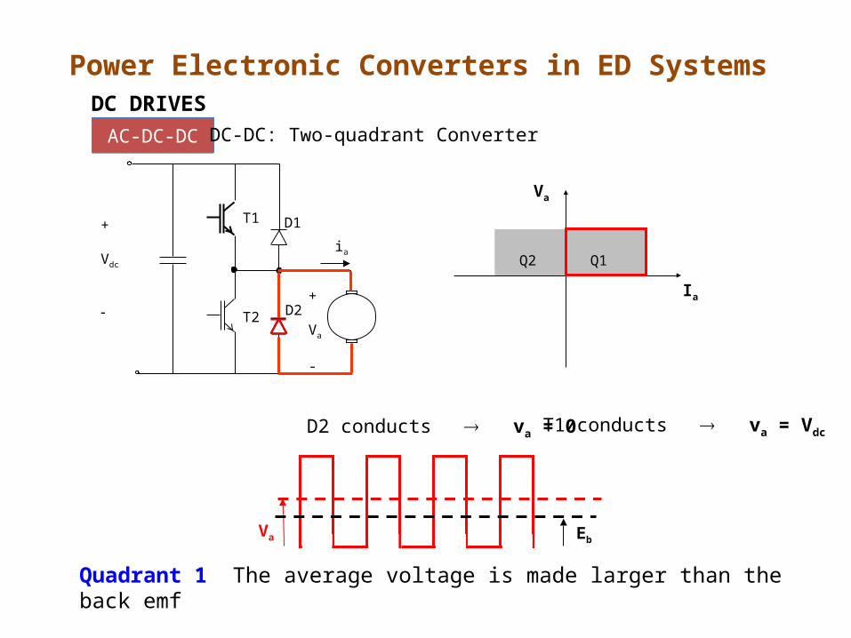
D2 conducts va = 0
Va Eb
T1 conducts va = Vdc
Quadrant 1 The average voltage is made larger than the back emf
DC DRIVES
AC-DC-DCAC-DC-DC DC-DC: Two-quadrant Converter
Power Electronic Converters in ED Systems
Page 35
Q1Q2
Va
Ia
T1
T2
D1
+
Va
-
D2
ia
+
Vdc
D1 conducts va = Vdc
DC DRIVES
AC-DC-DCAC-DC-DC DC-DC: Two-quadrant Converter
Power Electronic Converters in ED Systems
Page 36
Q1Q2
Va
Ia
T1
T2
D1
+
Va
-
D2
ia
+
Vdc
T2 conducts va = 0
VaEb
D1 conducts va = Vdc
Quadrant 2 The average voltage is made smallerr than the back emf, thus forcing the current to flow in the reverse direction
DC DRIVES
AC-DC-DCAC-DC-DC DC-DC: Two-quadrant Converter
Power Electronic Converters in ED Systems
Page 37
DC DRIVES
AC-DC-DCAC-DC-DC DC-DC: Two-quadrant Converter
+vc
2vtri
vc
+vA
-
Vdc
0
Power Electronic Converters in ED Systems
Page 38
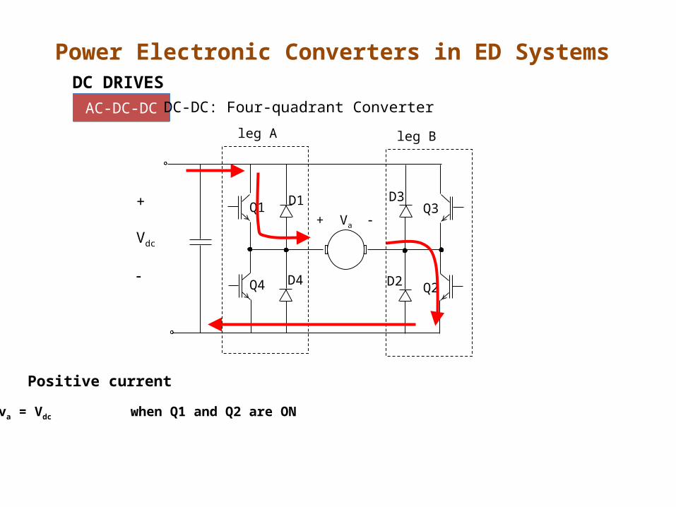
leg A leg B
+ Va Q1
Q4
Q3
Q2
D1 D3
D2D4
+
Vdc
va = Vdc when Q1 and Q2 are ON
Positive current
Power Electronic Converters in ED SystemsDC DRIVES
AC-DC-DCAC-DC-DC DC-DC: Four-quadrant Converter
Page 39
leg A leg B
+ Va Q1
Q4
Q3
Q2
D1 D3
D2D4
+
Vdc
va = -Vdc when D3 and D4 are ON
va = Vdc when Q1 and Q2 are ON
va = 0 when current freewheels through Q and D
Positive current
Power Electronic Converters in ED SystemsDC DRIVES
AC-DC-DCAC-DC-DC DC-DC: Four-quadrant Converter
Page 40
va = -Vdc when D3 and D4 are ON
va = Vdc when Q1 and Q2 are ON
va = 0 when current freewheels through Q and D
Positive current
va = Vdc when D1 and D2 are ON
Negative current
leg A leg B
+ Va Q1
Q4
Q3
Q2
D1 D3
D2D4
+
Vdc
Power Electronic Converters in ED SystemsDC DRIVES
AC-DC-DCAC-DC-DC DC-DC: Four-quadrant Converter
Page 41
va = -Vdc when D3 and D4 are ON
va = Vdc when Q1 and Q2 are ON
va = 0 when current freewheels through Q and D
Positive current
va = -Vdc when Q3 and Q4 are ON
va = Vdc when D1 and D2 are ON
va = 0 when current freewheels through Q and D
Negative current
leg A leg B
+ Va Q1
Q4
Q3
Q2
D1 D3
D2D4
+
Vdc
Power Electronic Converters in ED SystemsDC DRIVES
AC-DC-DCAC-DC-DC DC-DC: Four-quadrant Converter
Page 42
Power Electronic Converters in ED SystemsDC DRIVES
AC-DC-DCAC-DC-DC
vAB
Vdc
-Vdc
Vdc
0vB
vAVdc
0
2vtri
vc
vc
+
_
Vdc+vA
-
+vB
-
Bipolar switching scheme – output swings between VDC and -VDC
Page 43
Power Electronic Converters in ED SystemsDC DRIVES
AC-DC-DCAC-DC-DCUnipolar switching scheme – output swings between Vdc and -Vdc
Vtri
vc
-vc
vc
+
_
Vdc+vA
-
+vB
-
-vc
vA
Vdc
0
vB
Vdc
0
vAB
Vdc
0
Page 44
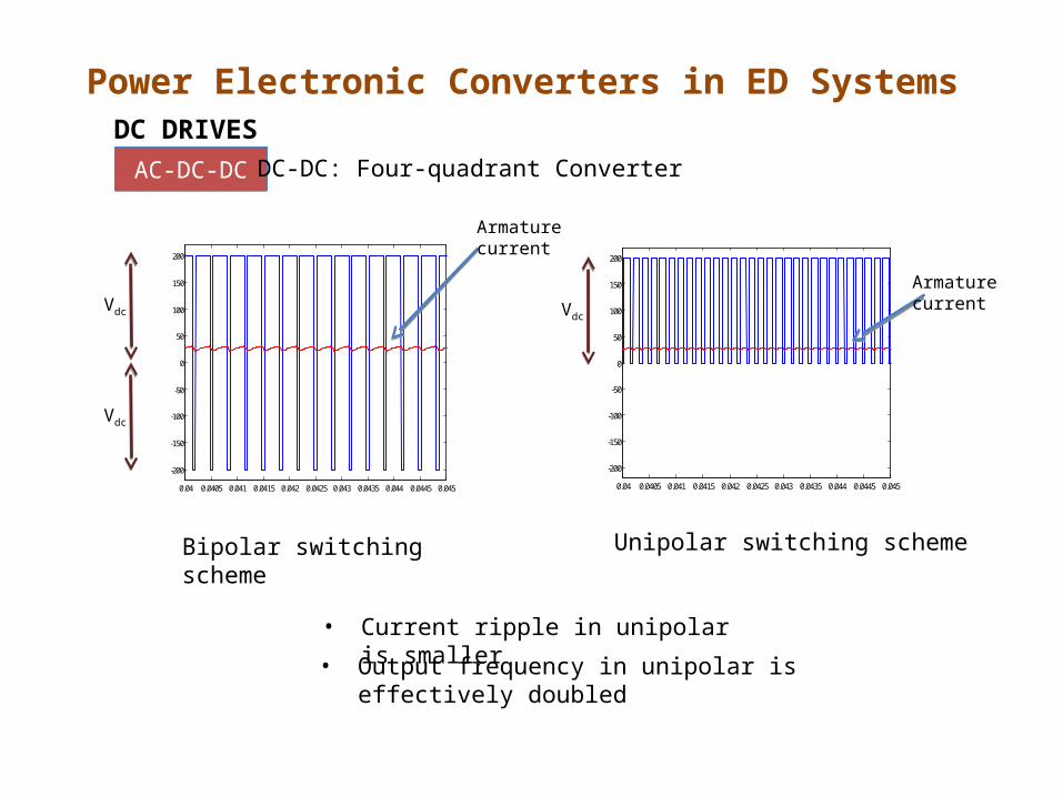
Power Electronic Converters in ED SystemsDC DRIVES
AC-DC-DCAC-DC-DC
Bipolar switching scheme
0.04 0.0405 0.041 0.0415 0.042 0.0425 0.043 0.0435 0.044 0.0445 0.045
-200
-150
-100
-50
0
50
100
150
200
Unipolar switching scheme
0.04 0.0405 0.041 0.0415 0.042 0.0425 0.043 0.0435 0.044 0.0445 0.045
-200
-150
-100
-50
0
50
100
150
200
• Current ripple in unipolar is smaller
• Output frequency in unipolar is effectively doubled
Vdc
Vdc
Vdc
DC-DC: Four-quadrant Converter
Armature current
Armature current
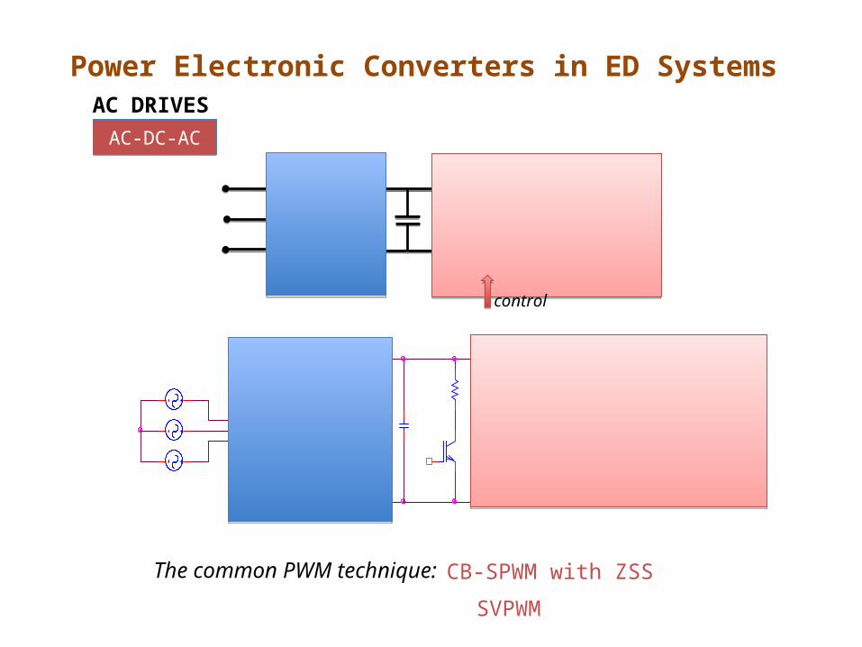
Page 45
Power Electronic Converters in ED SystemsAC DRIVES
AC-DC-ACAC-DC-AC
control
The common PWM technique: CB-SPWM with ZSS
SVPWM
Page 46
Modeling and Control of Electrical Drives
• Control the torque, speed or position
• Cascade control structure
Motor
Example of current control in cascade control structure
converterspeed
controllerposition
controller
+*
1/s
+ +
current
controller
T**
kT
Page 47
Modeling and Control of Electrical Drives
Current controlled converters in DC Drives - Hysteresis-based
iref
+
Vdc
−
ia
iref
va
+
Va
ierr
ierr
q
q
• High bandwidth, simple implementation, insensitive to parameter variations
• Variable switching frequency – depending on operating conditions
+
_
Page 48
Modeling and Control of Electrical Drives
Current controlled converters in AC Drives - Hysteresis-based
3-phaseAC Motor
+
+
+
i*a
i*b
i*c
Converter
• For isolated neutral load, ia + ib + ic = 0 control is not totally independent
• Instantaneous error for isolated neutral load can reach double the band
Page 49
Modeling and Control of Electrical Drives
Current controlled converters in AC Drives - Hysteresis-based
id
iq
is
hh hh
• For isolated neutral load, ia + ib + ic = 0 control is not totally independent
• Instantaneous error for isolated neutral load can reach double the band
Page 50
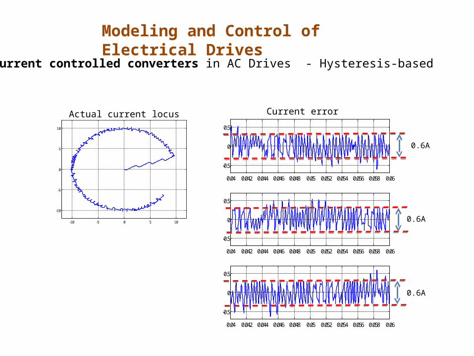
Modeling and Control of Electrical Drives
Current controlled converters in AC Drives - Hysteresis-based
powergui
Continuous
Universal Bridge 1
g
A
B
C
+
-
To Workspace1
iaref
Subsystem
c1
c2
c3
ina
inb
inc
p1
p2
p3
p4
p5
p6
Sine Wave 2
Sine Wave 1
Sine Wave
Series RLC Branch 3
Series RLC Branch 2
Series RLC Branch 1
Scope
DC Voltage Source Current Measurement 3
i+ -
Current Measurement 2
i+ -
Current Measurement 1
i+ -
• h = 0.3 A• Sinusoidal reference current, 30Hz
• Vdc = 600V• mH load
Page 51
Modeling and Control of Electrical Drives
Current controlled converters in AC Drives - Hysteresis-based
0.005 0.01 0.015 0.02 0.025 0.03
-10
-5
0
5
10
Actual and reference currents Current error
-0.5 -0.4 -0.3 -0.2 -0.1 0 0.1 0.2 0.3 0.4 0.5
-0.5
-0.4
-0.3
-0.2
-0.1
0
0.1
0.2
0.3
0.4
0.5
4 6 8 10 12 14 16
x 10-3
4
5
6
7
8
9
10
Page 52
Modeling and Control of Electrical Drives
Current controlled converters in AC Drives - Hysteresis-based
-10 -5 0 5 10
-10
-5
0
5
10
Actual current locus
0.04 0.042 0.044 0.046 0.048 0.05 0.052 0.054 0.056 0.058 0.06
-0.5
0
0.5
0.04 0.042 0.044 0.046 0.048 0.05 0.052 0.054 0.056 0.058 0.06
-0.5
0
0.5
0.04 0.042 0.044 0.046 0.048 0.05 0.052 0.054 0.056 0.058 0.06
-0.5
0
0.5
0.6A
0.6A
0.6A
Current error
Page 53
vtri
Vdc
qvc
q
Vdc
Pulse widthmodulator
vc
Vdc
Pulse widthmodulator
vciref
PI+
q
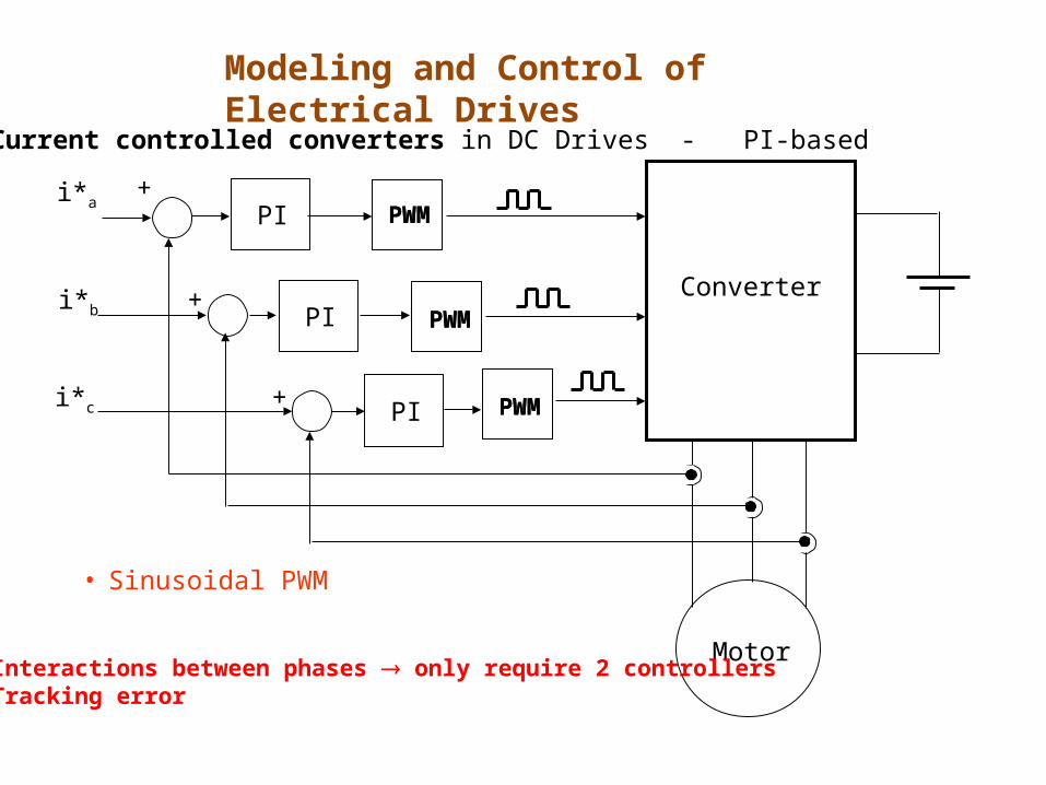
Modeling and Control of Electrical Drives
Current controlled converters in DC Drives - PI-based
Page 54
Motor
+
+
+
i*a
i*b
i*c
Converter
PWM
PWM
PWM
PWM
PWM
PWM
• Sinusoidal PWM
PI
PI
PI
• Interactions between phases only require 2 controllers• Tracking error
Modeling and Control of Electrical Drives
Current controlled converters in DC Drives - PI-based
Page 55
• Interactions between phases only require 2 controllers• Tracking error
• Perform the control in synchronous frame - the current will appear as DC
• Perform the 3-phase to 2-phase transformation - only two controllers (instead of 3) are used
Modeling and Control of Electrical Drives
Current controlled converters in DC Drives - PI-based
Page 56
Motor
i*a
i*b
i*c
Converter
PWM
+
+
+
PWM
PWM
PI
PI
PI
Modeling and Control of Electrical Drives
Current controlled converters in AC Drives - PI-based
Page 57
Motor
i*a
i*b
i*c
Converter
3-2
3-2
SVM2-3
PI
PI
Modeling and Control of Electrical Drives
Current controlled converters in AC Drives - PI-based
Page 58
id*
iq*
PIcontroller
dqabc
abcdq
SVM or SPWM
VSIIM
va*
vb*
vc*
id
iq
+
+
PIcontroller
Synch speed estimator
s
s
Modeling and Control of Electrical Drives
Current controlled converters in AC Drives - PI-based
Page 59
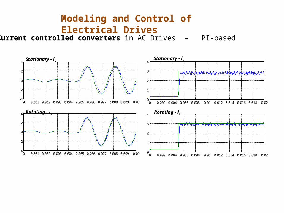
Modeling and Control of Electrical Drives
0 0.001 0.002 0.003 0.004 0.005 0.006 0.007 0.008 0.009 0.01-4
-2
0
2
4
0 0.001 0.002 0.003 0.004 0.005 0.006 0.007 0.008 0.009 0.01-4
-2
0
2
4
0 0.002 0.004 0.006 0.008 0.01 0.012 0.014 0.016 0.018 0.020
1
2
3
4
0 0.002 0.004 0.006 0.008 0.01 0.012 0.014 0.016 0.018 0.020
1
2
3
4
Stationary - iaStationary - id
Rotating - ia Rotating - id
Current controlled converters in AC Drives - PI-based
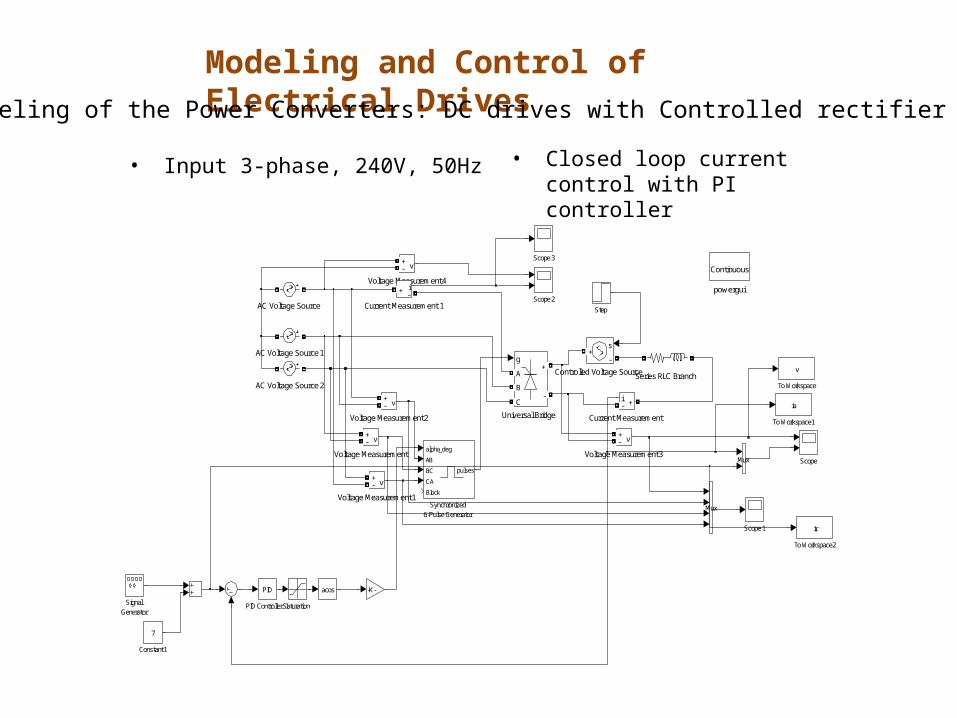
Page 60
Modeling and Control of Electrical DrivesModeling of the Power Converters: DC drives with Controlled rectifier
firingcircuit
controlled rectifier
+
Va
–
vc
va(s)vc(s)DC motor
The relation between vc and va is determined by the firing circuit
?
It is desirable to have a linear relation between vc and va
Page 61
Modeling and Control of Electrical DrivesModeling of the Power Converters: DC drives with Controlled rectifier
Cosine-wave crossing control
Vm
vsvc
0 2 3 4
Input voltage
Cosine wave compared with vc
Results of comparison trigger SCRs
Output voltage
Page 62
Modeling and Control of Electrical DrivesModeling of the Power Converters: DC drives with Controlled rectifier
Cosine-wave crossing control
Vm
vsvc
0 2 3 4
Vscos(t)Vscos() = vc
s
c1
vv
cos
cosV2
V ma
s
c1ma v
vcoscos
V2V
s
cma v
vV2V
A linear relation between vc and Va
Page 63
Va is the average voltage over one period of the waveform - sampled data system
Delays depending on when the control signal changes – normally taken as half of sampling period
Modeling and Control of Electrical DrivesModeling of the Power Converters: DC drives with Controlled rectifier
Page 64
Va is the average voltage over one period of the waveform - sampled data system
Delays depending on when the control signal changes – normally taken as half of sampling period
Modeling and Control of Electrical DrivesModeling of the Power Converters: DC drives with Controlled rectifier
Page 65
s2
T
H Ke)s(G
vc(s) Va(s)
s
m
V
V2K
Single phase, 50Hz
T=10ms
s
m,LL
V
V3K
Three phase, 50Hz
T=3.33ms
Simplified if control bandwidth is reduced to much lower than the sampling frequency
Modeling and Control of Electrical DrivesModeling of the Power Converters: DC drives with Controlled rectifier
Page 66
firingcircuit
currentcontroller
controlled rectifier
+
Va
–
vciref
• To control the current – current-controlled converter• Torque can be controlled• Only operates in Q1 and Q4 (single converter topology)
Modeling and Control of Electrical DrivesModeling of the Power Converters: DC drives with Controlled rectifier
Page 67
Modeling and Control of Electrical DrivesModeling of the Power Converters: DC drives with Controlled rectifier
powergui
ContinuousVoltage Measurement4
v+-
Voltage Measurement3
v+-
Voltage Measurement2
v+-
Voltage Measurement1
v+-
Voltage Measurement
v+-
Universal Bridge
g
A
B
C
+
-
acos
To Workspace2
ir
To Workspace1
ia
To Workspace
v
Synchronized6-Pulse Generator
alpha_deg
AB
BC
CA
Block
pulses
Step
SignalGenerator
Series RLC Branch
Scope3
Scope2
Scope1
Scope
SaturationPID Controller 1
PID
Mux
Mux
-K-
Current Measurement 1
i+ -
Current Measurement
i +-
Controlled Voltage Source
s
-+
Constant1
7
AC Voltage Source2
AC Voltage Source1
AC Voltage Source
• Input 3-phase, 240V, 50Hz • Closed loop current control with PI controller
Page 68
Modeling and Control of Electrical DrivesModeling of the Power Converters: DC drives with Controlled rectifier
• Input 3-phase, 240V, 50Hz • Closed loop current control with PI controller
0.1 0.2 0.3 0.4 0.5 0.6 0.7 0.8-500
0
500
1000
0.1 0.2 0.3 0.4 0.5 0.6 0.7 0.80
5
10
15
Voltage
Current
0.22 0.23 0.24 0.25 0.26 0.27 0.28-500
0
500
1000
0.22 0.23 0.24 0.25 0.26 0.27 0.280
5
10
15
Page 69
Modeling and Control of Electrical DrivesModeling of the Power Converters: DC drives with SM Converters
Page 70
vc
+
Va
−
vtri
Vdc
q
Switching signals obtained by comparing control signal with triangular wave
Va(s)vc(s)DC motor
We want to establish a relation between vc and Va
?
AVERAGE voltage
Modeling and Control of Electrical DrivesModeling of the Power Converters: DC drives with SM Converters
Page 71
dtqT1
dtriTt
ttri
tri
on
Tt
Vdc
0
Ttri
ton
0
1
01
qVc > Vtri
Vc < Vtrivc
dc
dT
0 dctri
a dVdtVT1
Vtri
Modeling and Control of Electrical DrivesModeling of the Power Converters: DC drives with SM Converters
Page 72
-Vtri
Vtri
-Vtri
vc
d
vc
0.5
For vc = -Vtri d = 0
Modeling and Control of Electrical DrivesModeling of the Power Converters: DC drives with SM Converters
Page 73
Modeling and Control of Electrical DrivesModeling of the Power Converters: DC drives with SM Converters
0.5
Vtri
Vtri
vc
d
vc
-Vtri-Vtri
For vc = -Vtri d = 0
For vc = 0 d = 0.5
For vc = Vtri d = 1
Page 74
Modeling and Control of Electrical DrivesModeling of the Power Converters: DC drives with SM Converters
0.5
vc
d
-Vtri-Vtri
ctri
vV21
5.0d
Vtri
Vtri
vc
For vc = -Vtri d = 0
For vc = 0 d = 0.5
For vc = Vtri d = 1
Page 75
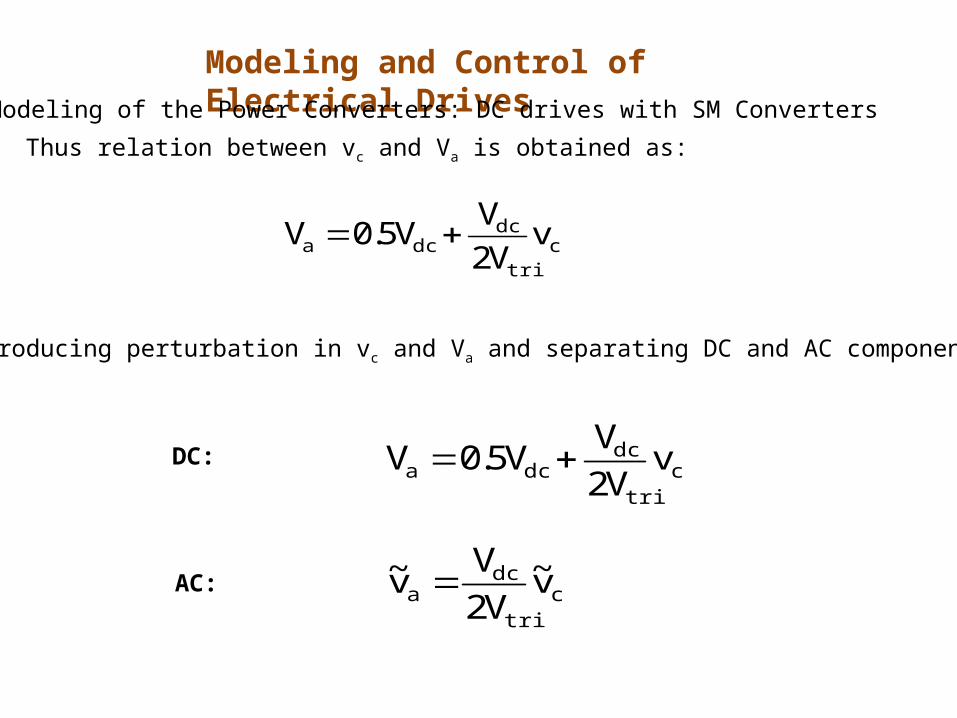
Thus relation between vc and Va is obtained as:
ctri
dcdca v
V2V
V5.0V
Introducing perturbation in vc and Va and separating DC and AC components:
ctri
dcdca v
V2V
V5.0V
ctri
dca v~
V2V
v~
DC:
AC:
Modeling and Control of Electrical DrivesModeling of the Power Converters: DC drives with SM Converters
Page 76
Taking Laplace Transform on the AC, the transfer function is obtained as:
tri
dc
c
a
V2V
)s(v)s(v
va(s)vc(s)DC motor
tri
dc
V2V
Modeling and Control of Electrical DrivesModeling of the Power Converters: DC drives with SM Converters
Page 77
2vtri
vc
vc
vtri+
Vdc
−
q-Vdc
q
Vdc
+ VAB
vAB
Vdc
-Vdc
ctri
dcABBA v
VV
VVV
tri
cAB V2
v5.0d1d
ctri
dcdcB v
V2V
V5.0V
vB
Vdc
0
tri
cA V2
v5.0d
ctri
dcdcA v
V2V
V5.0V
vA
Vdc
0
Modeling and Control of Electrical DrivesModeling of the Power Converters: DC drives with SM Converters
Bipolar switching scheme
Page 78
tri
dc
c
a
VV
)s(v)s(v
va(s)vc(s)DC motor
tri
dc
VV
Bipolar switching scheme
Modeling and Control of Electrical DrivesModeling of the Power Converters: DC drives with SM Converters
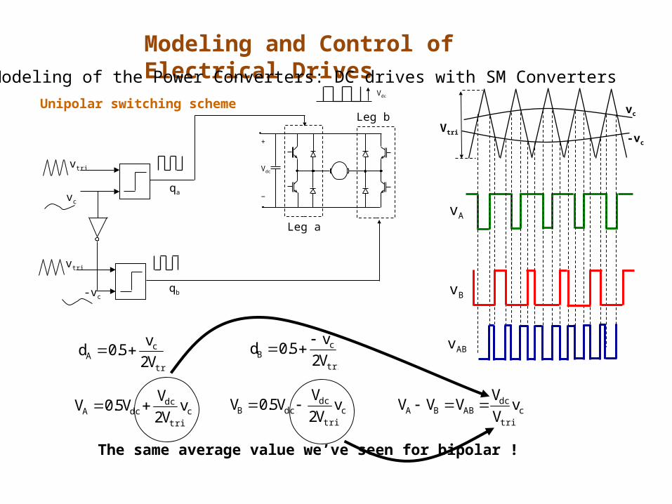
Page 79
+
Vdc
−vc
vtri
qa
Vdc
-vc
vtri
qb
Leg a
Leg b
The same average value we’ve seen for bipolar !
Vtri
vc
-vc
tri
cA V2
v5.0d
ctri
dcdcA v
V2V
V5.0V
vA
tri
cB V2
v5.0d
ctri
dcdcB v
V2V
V5.0V
vB
ctri
dcABBA v
VV
VVV
vAB
Unipolar switching scheme
Modeling and Control of Electrical DrivesModeling of the Power Converters: DC drives with SM Converters
Page 80
tri
dc
c
a
VV
)s(v)s(v
va(s)vc(s)DC motor
tri
dc
VV
Unipolar switching scheme
Modeling and Control of Electrical DrivesModeling of the Power Converters: DC drives with SM Converters
Page 81
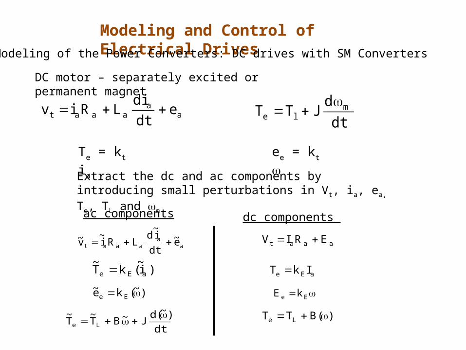
DC motor – separately excited or permanent magnet
Extract the dc and ac components by introducing small perturbations in Vt, ia, ea, Te, TL and m
aa
aaat edtdi
LRiv
Te = kt ia ee = kt
dtd
JTT mle
aa
aaat e~dti~
dLRi
~v~
)i~(kT
~aEe
)~(ke~ Ee
dt)~(d
J~BT~
T~
Le
ac components
aaat ERIV
aEe IkT
Ee kE
)(BTT Le
dc components
Modeling and Control of Electrical DrivesModeling of the Power Converters: DC drives with SM Converters
Page 82
Perform Laplace Transformation on ac components
aa
aaat e~dti~
dLRi
~v~
)i~(kT
~aEe
)~(ke~ Ee
dt)~(d
J~BT~
T~
Le
Vt(s) = Ia(s)Ra + LasIa + Ea(s)
Te(s) = kEIa(s)
Ea(s) = kE(s)
Te(s) = TL(s) + B(s) + sJ(s)
DC motor – separately excited or permanent magnet
Modeling and Control of Electrical DrivesModeling of the Power Converters: DC drives with SM Converters
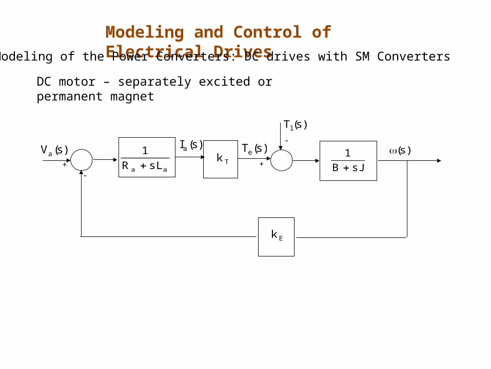
Page 83
Tkaa sLR
1
)s(Tl
)s(Te
sJB1
Ek
)s(Ia )s()s(Va
+-
-
+
DC motor – separately excited or permanent magnet
Modeling and Control of Electrical DrivesModeling of the Power Converters: DC drives with SM Converters
Page 84
Tc
vtri
+
Vdc
−
q
q
+
–
kt
Torque controller
Tkaa sLR
1
)s(Tl
)s(Te
sJB1
Ek
)s(Ia )s()s(Va
+-
-
+
Torquecontroller
Converter
peak,tri
dc
VV)s(Te
-+
DC motor
Modeling and Control of Electrical DrivesModeling of the Power Converters: DC drives with SM Converters
Page 85
Design procedure in cascade control structure
• Inner loop (current or torque loop) the fastest – largest bandwidth
• The outer most loop (position loop) the slowest – smallest bandwidth
• Design starts from torque loop proceed towards outer loops
Closed-loop speed control – an example
Modeling and Control of Electrical DrivesModeling of the Power Converters: DC drives with SM Converters
Page 86
OBJECTIVES:
• Fast response – large bandwidth
• Minimum overshoot good phase margin (>65o)
• Zero steady state error – very large DC gain
BODE PLOTS
• Obtain linear small signal model
METHOD
• Design controllers based on linear small signal model
• Perform large signal simulation for controllers verification
Closed-loop speed control – an example
Modeling and Control of Electrical DrivesModeling of the Power Converters: DC drives with SM Converters
Page 87
Ra = 2 La = 5.2 mH
J = 152 x 10–6 kg.m2B = 1 x10⁻⁴ kg.m2/sec
kt = 0.1 Nm/Ake = 0.1 V/(rad/s)
Vd = 60 V Vtri = 5 V
fs = 33 kHz
Closed-loop speed control – an example
• PI controllers • Switching signals from comparison of vc and triangular waveform
Modeling and Control of Electrical DrivesModeling of the Power Converters: DC drives with SM Converters
Page 88
Bode Diagram
Frequency (rad/sec)
-50
0
50
100
150From: Input Point To: Output Point
Mag
nitu
de (
dB)
10-2
10-1
100
101
102
103
104
105
-90
-45
0
45
90
Pha
se (
deg)
compensated
compensated
kpT= 90
kiT= 18000
Modeling and Control of Electrical DrivesModeling of the Power Converters: DC drives with SM Converters
Torque controller design Open-loop gain
Page 89
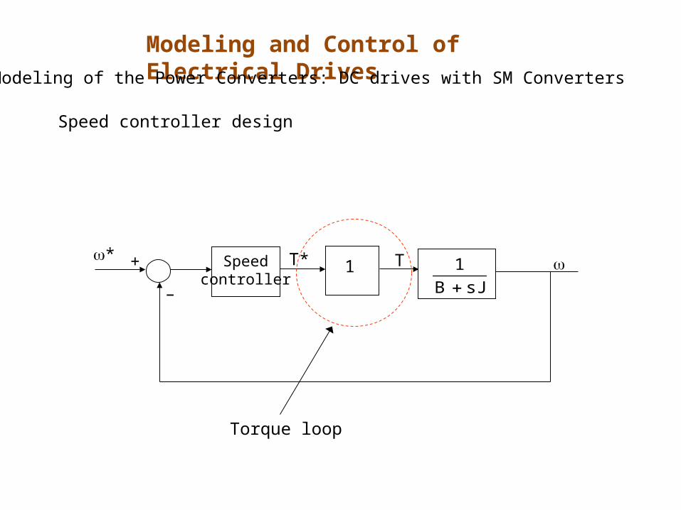
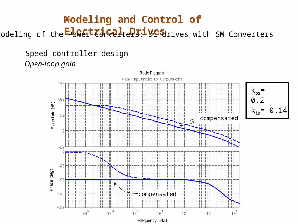
Speed controller design
1Speedcontroller sJB
1
* T* T
–
+
Torque loop
Modeling and Control of Electrical DrivesModeling of the Power Converters: DC drives with SM Converters
Page 90
Bode Diagram
Frequency (Hz)
-50
0
50
100
150From: Input Point To: Output Point
Mag
nitu
de (
dB)
10-2
10-1
100
101
102
103
104
-180
-135
-90
-45
0
Pha
se (
deg)
Open-loop gain
compensated
kps= 0.2
kis= 0.14
compensated
Speed controller design
Modeling and Control of Electrical DrivesModeling of the Power Converters: DC drives with SM Converters
Page 91
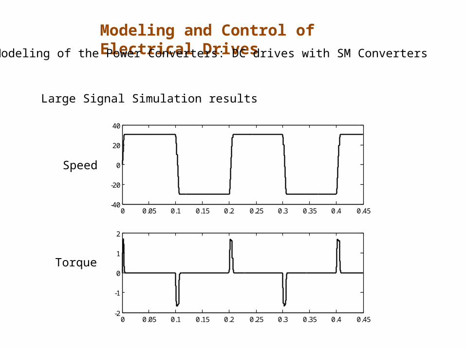
Large Signal Simulation results
0 0.05 0.1 0.15 0.2 0.25 0.3 0.35 0.4 0.45-40
-20
0
20
40
0 0.05 0.1 0.15 0.2 0.25 0.3 0.35 0.4 0.45-2
-1
0
1
2
Speed
Torque
Modeling and Control of Electrical DrivesModeling of the Power Converters: DC drives with SM Converters
Page 92
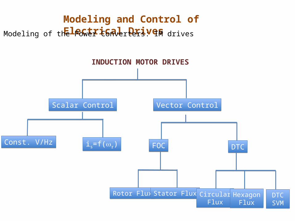
Modeling and Control of Electrical DrivesModeling of the Power Converters: IM drives
INDUCTION MOTOR DRIVES
Scalar ControlScalar Control Vector ControlVector Control
Const. V/HzConst. V/Hz is=f(r)is=f(r) FOCFOC DTCDTC
Rotor FluxRotor Flux Stator FluxStator Flux CircularFlux
CircularFlux
HexagonFlux
HexagonFlux
DTCSVMDTCSVM
Page 93
Control of induction machine based on steady-state model (per phase SS equivalent circuit):
Rr’/s
+
Vs
–
RsLls Llr’
+
Eag
–
Is Ir’
Im
Lm
Modeling and Control of Electrical DrivesModeling of the Power Converters: IM drives
Page 94
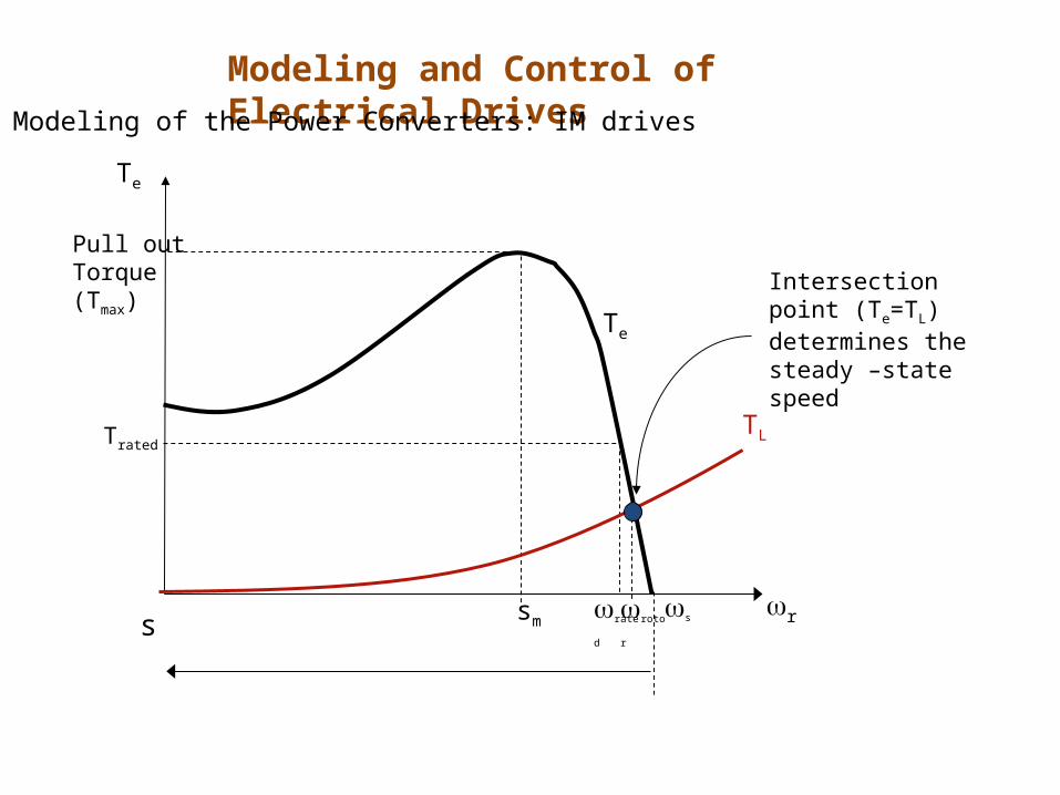
rs
Trated
Pull out Torque(Tmax)
Te
ssm ratedrotor
TL
Te
Intersection point (Te=TL) determines the steady –state speed
Modeling and Control of Electrical DrivesModeling of the Power Converters: IM drives
Page 95
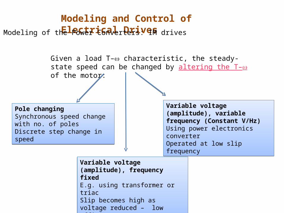
Given a load T– characteristic, the steady-state speed can be changed by altering the T– of the motor:
Pole changing Synchronous speed change with no. of polesDiscrete step change in speed
Pole changing Synchronous speed change with no. of polesDiscrete step change in speed
Variable voltage (amplitude), frequency fixedE.g. using transformer or triacSlip becomes high as voltage reduced – low efficiency
Variable voltage (amplitude), frequency fixedE.g. using transformer or triacSlip becomes high as voltage reduced – low efficiency
Variable voltage (amplitude), variable frequency (Constant V/Hz)Using power electronics converter Operated at low slip frequency
Variable voltage (amplitude), variable frequency (Constant V/Hz)Using power electronics converter Operated at low slip frequency
Modeling and Control of Electrical DrivesModeling of the Power Converters: IM drives
Page 96
Variable voltage, fixed frequency
0 20 40 60 80 100 120 140 1600
100
200
300
400
500
600
Tor
que
w (rad/s)
Lower speed slip higher
Low efficiency at low speed
e.g. 3–phase squirrel cage IM
V = 460 V Rs= 0.25
Rr=0.2 Lr = Ls = 0.5/(2*pi*50)
Lm=30/(2*pi*50)
f = 50Hz p = 4
Modeling and Control of Electrical DrivesModeling of the Power Converters: IM drives
Page 97
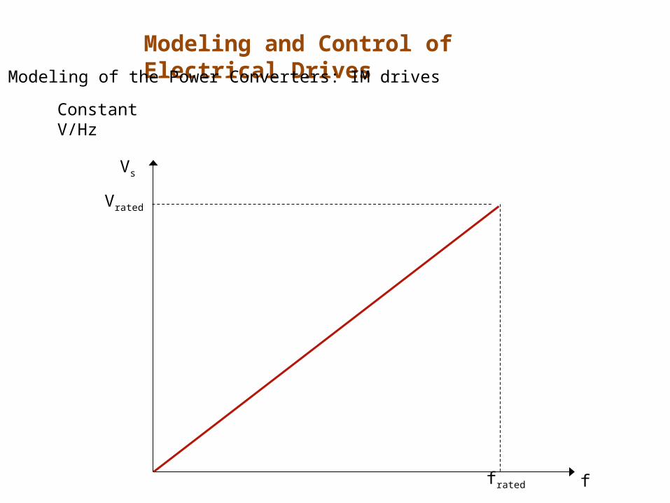
Constant V/Hz
Approximates constant air-gap flux when Eag is large
Eag = k f ag
f
V
f
Eag ag = constant
Speed is adjusted by varying f - maintaining V/f constant to avoid flux saturation
To maintain V/Hz constant
+V
_
+Eag
_
Modeling and Control of Electrical DrivesModeling of the Power Converters: IM drives
Page 98
0 20 40 60 80 100 120 140 1600
100
200
300
400
500
600
700
800
900
Tor
que
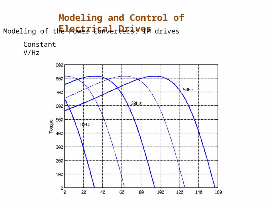
50Hz
30Hz
10Hz
Modeling and Control of Electrical DrivesModeling of the Power Converters: IM drives
Constant V/Hz
Page 99
Vrated
frated
Vs
f
Modeling and Control of Electrical DrivesModeling of the Power Converters: IM drives
Constant V/Hz
Page 100
VSIRectifier
3-phase supply IM
Pulse Width
Modulators*+
Rampf
C
V
Modeling and Control of Electrical DrivesModeling of the Power Converters: IM drives
Constant V/Hz
Page 101
Modeling and Control of Electrical DrivesModeling of the Power Converters: IM drives
To Workspace1
speed
To Workspace
torque
Subsystem
In1Out1
Step SliderGain1
0.41147Scope
Rate Limiter
Induction Machine
Va
Vb
Vc
isd
isq
ird
speed
Vd
irq
Vq
TeConstant V/Hz
In1
Out1
Out2
Out3
Constant V/Hz
Simulink blocks for Constant V/Hz Control
Page 102
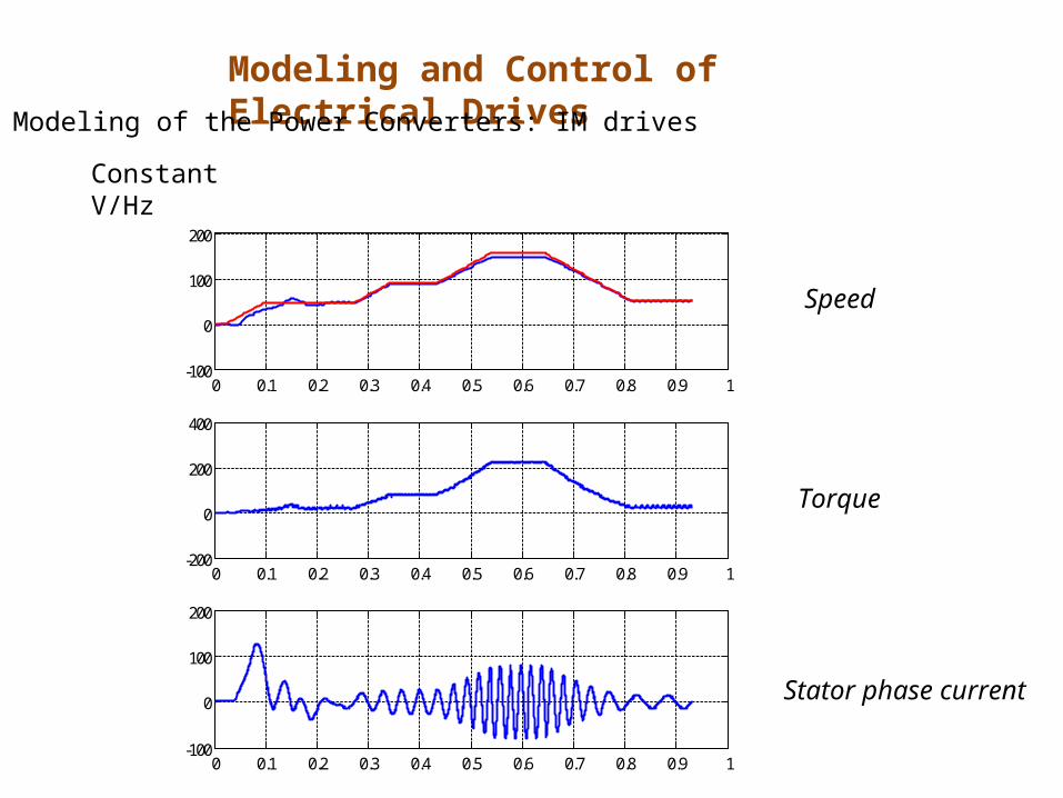
Modeling and Control of Electrical DrivesModeling of the Power Converters: IM drives
0 0.1 0.2 0.3 0.4 0.5 0.6 0.7 0.8 0.9 1-100
0
100
200
0 0.1 0.2 0.3 0.4 0.5 0.6 0.7 0.8 0.9 1-200
0
200
400
0 0.1 0.2 0.3 0.4 0.5 0.6 0.7 0.8 0.9 1-100
0
100
200
Constant V/Hz
Speed
Torque
Stator phase current
Page 103
1Problems with open-loop constant V/f
At low speed, voltage drop across stator impedance is significant compared to airgap voltage - poor torque capability at low speed
Solution:1. Boost voltage at low speed2. Maintain Im constant – constant ag
Modeling and Control of Electrical DrivesModeling of the Power Converters: IM drives
Page 104
Modeling and Control of Electrical DrivesModeling of the Power Converters: IM drives
0 20 40 60 80 100 120 140 1600
100
200
300
400
500
600
700
Tor
que
50Hz
30Hz
10Hz
A low speed, flux falls below the rated value
Page 105
With compensation (Is,ratedRs)
0 20 40 60 80 100 120 140 1600
100
200
300
400
500
600
700
Tor
que
• Torque deteriorate at low frequency – hence compensation commonly performed at low frequency
• In order to truly compensate need to measure stator current – seldom performed
Modeling and Control of Electrical DrivesModeling of the Power Converters: IM drives
Page 106
With voltage boost at low frequency
Vrated
frated
Linear offset
Non-linear offset – varies with IsBoost
Modeling and Control of Electrical DrivesModeling of the Power Converters: IM drives
Page 107
Poor speed regulation
Solution:1. Compesate slip2. Closed-loop control
Problems with open-loop constant V/f
2Modeling and Control of Electrical Drives
Modeling of the Power Converters: IM drives
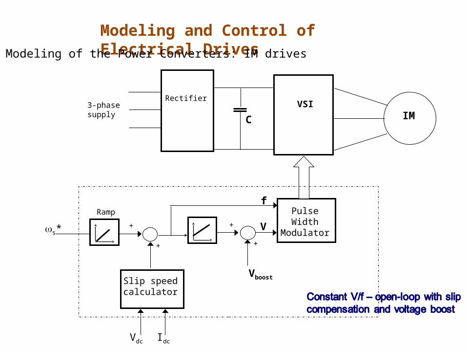
Page 108
VSIRectifier
3-phase supply IM
Pulse Width
Modulator
VboostSlip speed calculator
s*++
++ V
Vdc Idc
Rampf
C
Modeling and Control of Electrical DrivesModeling of the Power Converters: IM drives
Page 109
A better solution : maintain ag constant. How?
ag, constant → Eag/f , constant → Im, constant (rated)
maintain at rated
Controlled to maintain Im at rated
Modeling and Control of Electrical DrivesModeling of the Power Converters: IM drives
Rr’/s
+
Vs
–
RsLls Llr’
+
Eag
–
Is Ir’
Im
Lm
Page 110
0 20 40 60 80 100 120 140 1600
100
200
300
400
500
600
700
800
900
Tor
que
50Hz
30Hz
10Hz
Modeling and Control of Electrical DrivesModeling of the Power Converters: IM drives
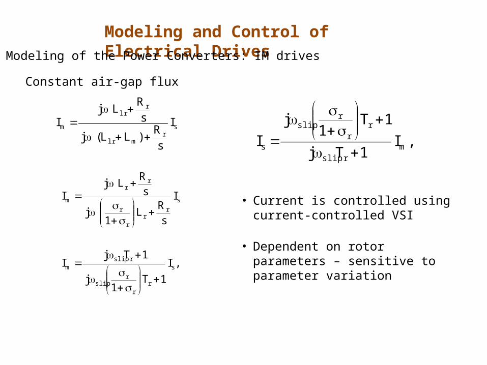
Constant air-gap flux
Page 111
sr
mlr
rlr
m I
sR
)LL(j
sR
LjI
,I
1T1
j
1TjI
I
sR
L1
j
sR
LjI
s
rr
rslip
rslipm
s
rr
r
r
rr
m
,I1Tj
1T1
j
I mrslip
rr
rslip
s
• Current is controlled using current-controlled VSI
• Dependent on rotor parameters – sensitive to parameter variation
Modeling and Control of Electrical DrivesModeling of the Power Converters: IM drives
Constant air-gap flux
Page 112
VSIRectifier
3-phase supply IM
*
+
+ |Is|slip
C
Current controller
s
PI
+
r
-
Modeling and Control of Electrical DrivesModeling of the Power Converters: IM drives
Constant air-gap flux
Page 113
THANK YOUTHANK YOU