Power Electronics Materials and Bonded Interfaces – Reliability and Lifetime Paul Paret National Renewable Energy Laboratory June 2, 2020 DOE Vehicle Technologies Program 2020 Annual Merit Review and Peer Evaluation Meeting This presentation does not contain any proprietary, confidential, or otherwise restricted information. Project ID # ELT219
Transcript
Power Electronics Materials and Bonded Interfaces – Reliability and LifetimePaul ParetNational Renewable Energy LaboratoryJune 2, 2020
DOE Vehicle Technologies Program 2020 Annual Merit Review and Peer Evaluation Meeting
This presentation does not contain any proprietary, confidential, or otherwise restricted information.
o DOE share: $175K• Funding for FY 2019: $175K• Funding for FY 2020: $175K
Timeline Barriers
Partners
• Cost• Size and Weight• Performance, Reliability, and Lifetime
• Interactions/collaborationso Virginia Polytechnic Institute and State
University (Prof. G. Q. Lu)o Georgia Institute of Technology (Prof. Samuel
Graham)o Oak Ridge National Laboratory (ORNL)o Ames Laboratory
• Project leado National Renewable Energy Laboratory (NREL)
NREL | 3
Relevance – Materials for High-Temperature Power Electronics
• Wide-bandgap devices such as silicon carbide and gallium nitride enable low-cost,lightweight, and power-dense automotive power electronics; however, thesetechnologies are currently limited by power electronic packaging.
• It is critical that the packaging design and materials withstand the high-temperatureoperational environment introduced by the wide-bandgap devices; bonded interfacesmust be reliable under extreme thermal stress conditions.
• The main objective of this project is to evaluate the reliability and study the failuremechanisms of bonded interface materials for high-temperature power electronicapplications.
High-Temperature Bonded Materials
Thermomechanical Performance
Reliability and Failure Mechanisms
Lifetime Prediction
NREL | 4
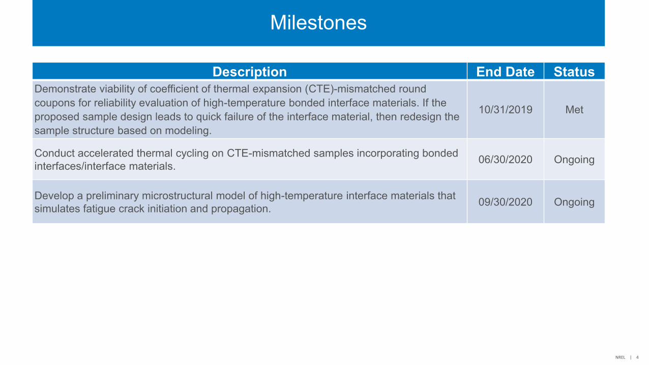
Milestones
Description End Date StatusDemonstrate viability of coefficient of thermal expansion (CTE)-mismatched round coupons for reliability evaluation of high-temperature bonded interface materials. If the proposed sample design leads to quick failure of the interface material, then redesign the sample structure based on modeling.
Develop a preliminary microstructural model of high-temperature interface materials that simulates fatigue crack initiation and propagation. 09/30/2020 Ongoing
NREL | 5
Overall Approach
Bonded MaterialExperimental Modeling
Sample synthesis/bonding
Mechanical Characterization
Reliability Evaluation –Thermal Cycling
Failure Mechanisms
Finite Element Analysis
Strain Energy Density J-Integral
Crack Propagation Model (XFEM)
XFEM – Extended Finite Element Method
Lifetime Prediction
NREL | 6
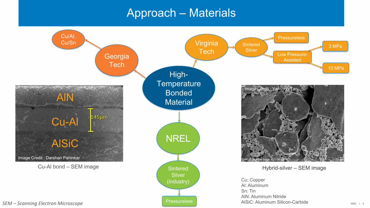
Approach – Materials
Pressureless
Hybrid-silver – SEM image
Cu-Al
AlN
AlSiC
Cu-Al bond – SEM image
Cu: CopperAl: AluminumSn: Tin AlN: Aluminum NitrideAlSiC: Aluminum Silicon-CarbideSEM – Scanning Electron Microscope
Image Credit : Yansong Tan
Image Credit : Darshan Pahinkar
High-Temperature
Bonded Material
Virginia Tech
SinteredSilver
Pressureless
Low Pressure-Assisted
NREL
Sintered Silver
(industry)
Georgia Tech
Cu/Al, Cu/Sn
3 MPa
10 MPa
NREL | 7
Approach – Reliability Evaluation
ɸ1-inch Copper and Invar Coupons: non-plated (top), plated with 4-µm-thick silver
(bottom)
Image Credit: Douglas DeVoto
-100
0
100
200
0 5 10 15 20 25
Tem
pera
ture
(°C
)
Time (min)
Thermal Cycle
Samples placed on thermal platform for thermal cycling, C-SAM images of these samples are taken periodically
Credit: Joshua Major
Samples with three different bond diameters were fabricated: 22 mm (left), 16 mm (center), and 10 mm (right)
Technical Accomplishments and Progress:Reliability of Sintered Silver – 3 MPa Sintering Pressure
• Most of the samples exhibited very good initial bond quality—voidfraction was calculated to be less than 2%.
• The rapid failure of these samples factored out any correlationbetween sample design variables (bond diameter) and reliability.
• Sample evaluations were first performed after 50 cycles but it likelythat samples failed* in 20 or 30 cycles.
• Cross-sectional images reveal the failure mechanisms to be mostlyadhesive in nature with near-vertical cohesive cracks in between.
Cross-sectional image of cracks formed in sintered silver bond under thermal cycling: sintering pressure – 3 MPa; bond diameter – 16 mm
*Failure – 20% void fraction; void fraction on the y-axes here includes the initial voidsand the cracks formed under thermal cycling.
0%
10%
20%
30%
40%
50%
60%
70%
0 20 40 60 80 100 120
Vo
id F
ract
ion
Thermal Cycles
Cu side
10 mm
16 mm
22 mm
0%
10%
20%
30%
40%
50%
60%
70%
0 20 40 60 80 100 120
Vo
id F
ract
ion
Thermal Cycles
Invar side
10 mm
16 mm
22 mm
0%
10%
20%
30%
40%
50%
60%
70%
0 20 40 60 80 100 120
Vo
id F
ract
ion
Thermal Cycles
Average
10 mm
16 mm
22 mm
NREL | 9
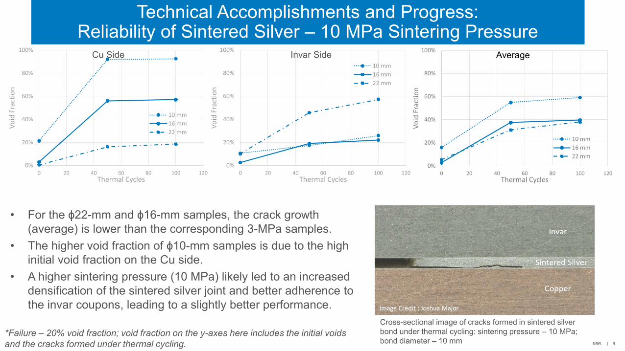
Technical Accomplishments and Progress:Reliability of Sintered Silver – 10 MPa Sintering Pressure
• For the ɸ22-mm and ɸ16-mm samples, the crack growth(average) is lower than the corresponding 3-MPa samples.
• The higher void fraction of ɸ10-mm samples is due to the highinitial void fraction on the Cu side.
• A higher sintering pressure (10 MPa) likely led to an increaseddensification of the sintered silver joint and better adherence tothe invar coupons, leading to a slightly better performance.
Cross-sectional image of cracks formed in sintered silver bond under thermal cycling: sintering pressure – 10 MPa; bond diameter – 10 mm
0%
20%
40%
60%
80%
100%
0 20 40 60 80 100 120
Vo
id F
ract
ion
Thermal Cycles
Cu Side
10 mm
16 mm
22 mm
0%
20%
40%
60%
80%
100%
0 20 40 60 80 100 120
Vo
id F
ract
ion
Thermal Cycles
Invar Side10 mm
16 mm
22 mm
0%
20%
40%
60%
80%
100%
0 20 40 60 80 100 120
Vo
id F
ract
ion
Thermal Cycles
Average
10 mm
16 mm
22 mm
*Failure – 20% void fraction; void fraction on the y-axes here includes the initial voidsand the cracks formed under thermal cycling.
NREL | 10
Technical Accomplishments and Progress:Comparison with Solder Joints
SAC305
95Pb5Sn
• SAC305 samples were subjected to −40°C to 150°C and95Pb5Sn samples to −40°C to 200°C, for reference.
• Pressureless sintered silver samples (ɸ10mm) failed in just 10cycles under −40°C to 150°C.
• For both solders, crack growth is dominant at the Cu side;failure mechanisms are likely to be cohesive in nature given theslow rate of crack growth.
• Despite the higher initial void fraction in 95Pb5Sn sample,crack propagation is slower, indicating higher reliability*.
0%
10%
20%
30%
40%
50%
60%
0 20 40 60 80 100 120
Void
Fra
ctio
n
Thermal Cycles
-40°C – 200°C
95Pb5Sn
3 MPa - Sintered Silver
10 MPa - Sintered Silver
0%
5%
10%
15%
20%
25%
30%
35%
40%
0 20 40 60 80 100 120 140
Cra
ck G
row
th
Thermal Cycles
-40°C – 150°C
SAC305
0 MPa - Sintered Silver
* - Based on results averaged from two 95Pb5Sn samples. More samples will be added to the matrix.
NREL | 11
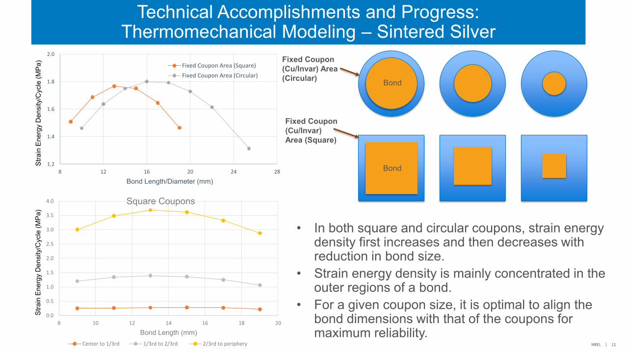
Technical Accomplishments and Progress:Thermomechanical Modeling – Sintered Silver
1.2
1.4
1.6
1.8
2.0
8 12 16 20 24 28
Stra
in E
nerg
y D
ensi
ty/C
ycle
(MPa
)
Bond Length/Diameter (mm)
Fixed Coupon Area (Square)
Fixed Coupon Area (Circular)
0.0
0.5
1.0
1.5
2.0
2.5
3.0
3.5
4.0
8 10 12 14 16 18 20
Stra
in E
nerg
y D
ensi
ty/C
ycle
(MPa
)
Bond Length (mm)
Square Coupons
Center to 1/3rd 1/3rd to 2/3rd 2/3rd to periphery
Fixed Coupon (Cu/Invar) Area (Circular)
Fixed Coupon (Cu/Invar) Area (Square)
Bond
Bond
• In both square and circular coupons, strain energydensity first increases and then decreases withreduction in bond size.
• Strain energy density is mainly concentrated in theouter regions of a bond.
• For a given coupon size, it is optimal to align thebond dimensions with that of the coupons formaximum reliability.
NREL | 12
Technical Accomplishments and Progress:Synthesis of Transient Liquid Phase Cu-Al Bonds
• Mechanical Characterizationo Single-lap configuration designed for conducting shear
strength characterization of the Cu-Al alloy bond.o Trial samples were synthesized at Georgia Tech and sent
to NREL for evaluation.
• Reliability Evaluationo Selected sample configuration: Cu bonded to AlSiC
coupons using Cu-Al alloy, footprint is 1-inch x 1-inch.o Trial samples synthesized at Georgia Tech exhibited
cracking in the AlSiC layer.o Currently in the process of synthesis profile optimization
to improve bond quality.
Al
Grip Area
Cu-Al Bond
Single-Lap Specimen
3 mm
Side view
2 mmCu
AlSiC
Cu/Al
Sample design for reliability evaluation
Copper
Cu-Al
AlSiC
Cross-sectional image of Cu-AlSiC sample with Cu-Al bond. Cracking in AlSiC layer could be due to excessive Cu migration.
Image Credit : Chidinma Imediegwu
NREL | 13
Responses to Previous Year Reviewers’ Comments
The reviewer said the team seems to be collaborating well internally. It is unclear what the interaction with industry (original equipment manufacturer [OEM], Tier 1/Tier 2, and raw material suppliers) is to ensure that solutions being explored are relevant and transferrable.
The conclusions of this project are periodically presented before the Electrical and Electronics Tech Team, which consists of automotive OEMs. Also, information will be disseminated as publications in journals and conferences.
The reviewer said it is important to compare new bonding solutions to a baseline of materials and processes commonly used in the industry today. This should include metrics that incorporate not only reliability and performance of the bonding technology, but also measures of the investment, cost, and processing time.
Most of the current baseline materials used in the industry today are limited to 150°C or at most 175°C. The operational temperature of 200°C is very challenging, and we have compared the reliability of sintered silver with solder joints. Assessing the impact of investment, cost, and processing time are outside the scope of this project.
NREL | 14
Collaboration and Coordination
• Virginia Tech: technical partner on the synthesis of sintered silver bonds
• Georgia Tech: technical partner on the synthesis of transient liquidphase Cu/Al bonds
• ORNL: technical guidance
• Ames: technical guidance
NREL | 15
Remaining Challenges and Barriers
• Correlation between simulations and experimental results is hard to establishdue to the macroscopic nature of modeling and microstructural causes offailure mechanisms in bonded materials.
• While current formulations of sintered silver may work for small area attach(die-attach), novel material compositions and microstructures need to beidentified for large area attach layers with sufficient reliability.
• Synthesis profile and parameters of Cu-Al bond need to be optimized toreduce the initial void fraction to acceptable levels (<5%).
NREL | 16
Proposed Future Research – FY 2020
• Investigate the effect of sample stiffness on reliability—conduct accelerated thermal cycling onsintered silver samples with 1-mm-thick Cu and Invar coupons. (FY 2020 Milestone)
• Develop a preliminary microstructural crack propagation model—this model will be anadvancement over the current macroscale models to simulate and predict the failuremechanisms of sintered silver and other high-temperature bonded interface materials. (FY2020 Milestone)
• Conduct mechanical characterization of Cu/Al alloy at different strain rates and temperatures—develop a constitutive model that captures the deformation behavior of the Cu/Al alloy.
• Synthesize Cu/Al alloy samples with high bond quality (<5% initial void fraction)—optimize thesynthesis profile and investigate Al-Cu/Al-AlSiC structure in addition to the current Cu-Cu/Al-AlSiC configuration.
Any proposed future work is subject to change based on funding levels.
NREL | 17
Proposed Future Research – FY 2021
• Conduct accelerated thermal cycling of Cu/Al bond samples under differenttemperature profiles: −40°C to 200°C, −40°C to 175°C.
• Expand the microstructural crack propagation model to include physics atlower length and timescales and establish microstructure-propertyrelationships to accelerate novel high-temperature material development.
• Investigate the reliability and failure mechanisms of alternate high-temperaturematerials such as sintered copper and Cu-Sn transient alloys.
Any proposed future work is subject to change based on funding levels.
NREL | 18
Summary
• DOE Mission Supporto Reliability evaluation of bonded materials is a critical research area for enabling low-cost, lightweight, and reliable
power electronic packages that can operate at high temperatures.
• Approacho Synthesis of high-temperature bond materials, mechanical characterization, reliability evaluation,
thermomechanical modeling, and lifetime prediction models.
• Accomplishmentso Sintered silver may be a promising material for die-attach applications (from literature review), but solder joints
perform better than current formulations of sintered silver under −40°C to 200°C thermal cycling.o Modeling results, in general, show good correlation with experimental results of sintered silver and solder joints.o Preliminary synthesis of samples with Cu-Al bond alloy completed; synthesis profile and sample design will be
iterated to improve bond quality.
• Collaborationso Virginia Techo Georgia Techo Oak Ridge National Laboratoryo Ames Laboratory
www.nrel.gov
NREL/PR-5400-76672
Thank You
This work was authored by the National Renewable Energy Laboratory, operated by Alliance for Sustainable Energy, LLC, for the U.S. Department of Energy (DOE) under Contract No. DE-AC36-08GO28308. Funding provided by U.S. Department of Energy Office of Energy Efficiency and Renewable Energy Vehicle Technologies Office. The views expressed in the article do not necessarily represent the views of the DOE or the U.S. Government. The U.S. Government retains and the publisher, by accepting the article for publication, acknowledges that the U.S. Government retains a nonexclusive, paid-up, irrevocable, worldwide license to publish or reproduce the published form of this work, or allow others to do so, for U.S. Government purposes.