73
Power Electronics – Quo Vadis Frede Blaabjerg Professor, IEEE Fellow [email protected] Aalborg University Department of Energy Technology Aalborg, Denmark

Power Electronics – Quo Vadis
Frede Blaabjerg
Professor, IEEE Fellow
Aalborg University
Department of Energy Technology
Aalborg, Denmark

► Power Electronics and ComponentsState-of-the-art; Technology overview, global impact
► Renewable Energy SystemsPV; Wind power; Cost of Energy; Grid Codes
► Outlook
Outline
► Power Electronic Based Power System StabilityPower Converters in the grid, Stability, Mitigation
► Reliable Power ElectronicsReliabil ity, Design for reliabil ity, Physics of Failure

Power Electronics and Components

Energy Production | Distribution | Consumption | Control
Power Electronics in all aspects of Energy
4

CENTER OF RELIABLE POWER ELECTRONICS, AALBORG UNIVERSITY 5
►Transition of Energy System
Source: http://electrical-engineering-portal.com
Source: www.offshorewind.biz
Source: http://media.treehugger.com
from Central to De-central Power Generation
(Source: Danish Energy Agency)
(Source: Danish Energy Agency)
from large synchronous generators to
more power electronic converters
Towards 100% Power
Electronics Interfaced
Integration to electric grid
Power transmission
Power distribution
Power conversion
Power control
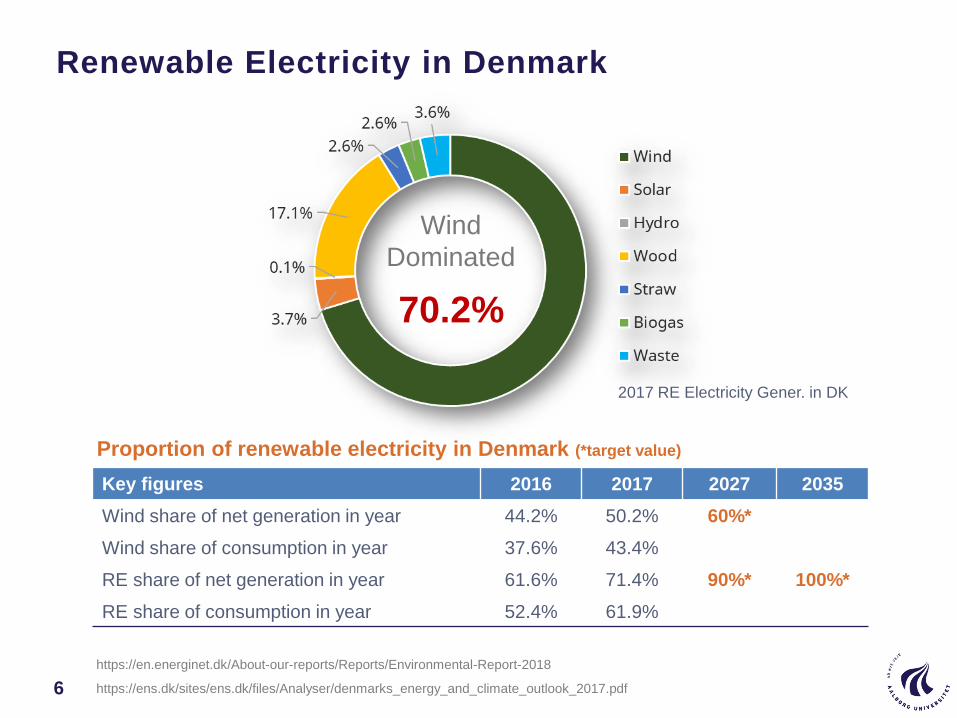
Renewable Electricity in Denmark
6
Proportion of renewable electricity in Denmark (*target value)
Key figures 2016 2017 2027 2035
Wind share of net generation in year 44.2% 50.2% 60%*
Wind share of consumption in year 37.6% 43.4%
RE share of net generation in year 61.6% 71.4% 90%* 100%*
RE share of consumption in year 52.4% 61.9%
2017 RE Electricity Gener. in DK
Wind
Dominated
70.2%
https://en.energinet.dk/About-our-reports/Reports/Environmental-Report-2018
https://ens.dk/sites/ens.dk/files/Analyser/denmarks_energy_and_climate_outlook_2017.pdf
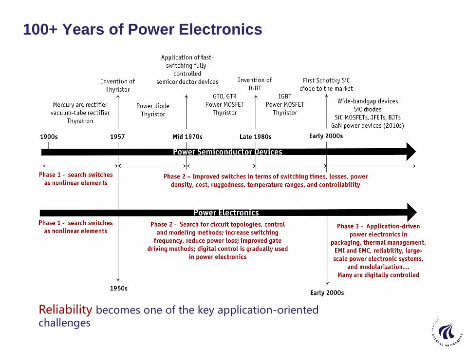
100+ Years of Power Electronics
Reliability becomes one of the key application-oriented challenges
CENTER OF RELIABLE POWER ELECTRONICS, AALBORG UNIVERSITY 8
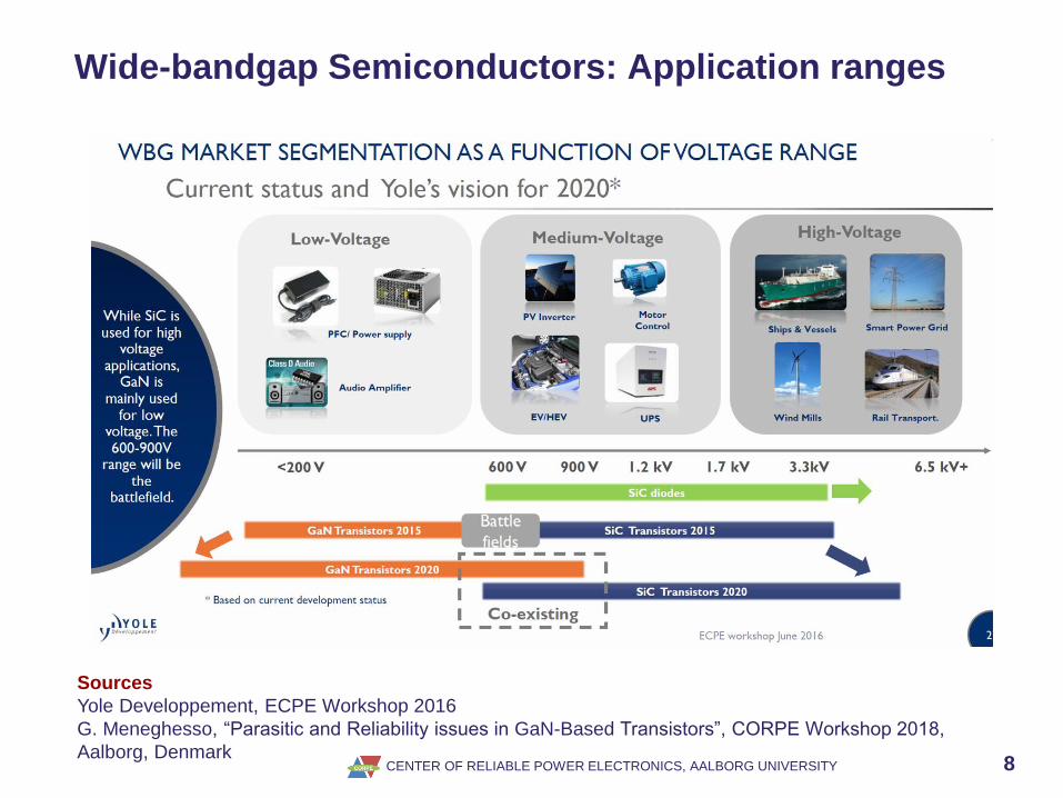
Wide-bandgap Semiconductors: Application ranges
Sources
Yole Developpement, ECPE Workshop 2016
G. Meneghesso, “Parasitic and Reliability issues in GaN-Based Transistors”, CORPE Workshop 2018,
Aalborg, Denmark

CENTER OF RELIABLE POWER ELECTRONICS, AALBORG UNIVERSITY 9
Wide-bandgap Semiconductors
Physical parameters of common wide-bandgap semiconductors in comparison with Silicon
Sources
Joachim Würfl, “GaN Power Devices (HEMT): Basics, Advantages and Perspectives”, ECPE Workshop
2013
G. Meneghesso, “Parasitic and Reliability issues in GaN-Based Transistors”, CORPE Workshop 2018,
Aalborg, Denmark

Typical Capacitors in Power Electronic Applications
Aluminum Electrolytic Capacitor
Sandwich(Source: http://www.jhdeli.com/Templates/Cold_Sandwich.html)
Capacitance Ripple current rating
Al-Caps
MPPF-Caps
MLC-Caps
Capac
itanc
e
Volta
ge
Rippl
e cu
rren
t
ESR and
DF
Cap. s
tabi
lity
Tem
pera
ture
Reliabi
lity
Energ
y de
nsity
Cost
Vol.
dera
ting
Freq
uenc
y
Superior intermediate InferiorRelative
Performance
Al-Caps Aluminum Electrolytic CapacitorsMPPF-Caps Metallized Polypropylene Film CapacitorsMLC-Caps Multilayer Ceramic Capacitors
Capacitors might be a bottleneck in modern power electronics

Concept of a Two-terminal Active Capacitor
Active Capacitor
§ Two-terminals only
§ Impedance characteristics equivalent to
passive capacitorsA B
Active switches
Passive elements
Sampling and conditioning
Micro-controller
Gate drivers
ABi
ABv
Self-power Supply
Feature No signal connection to main circuit
No auxiliary power supply
Only two-terminal ”A” and ”B” connected to external main circuit
Retain the same level of convenience as a conventional passive capacitor Application independent Lowest apparent power processed by the auxiliary circuit
Source: H. Wang, H. Wang and F. Blaabjerg, ¨A two-terminal active capacitor device¨

Proof-of-Concept of a Two-terminal Active Capacitor
An implementation of the two-terminal active capacitor concept
Internal auxiliary power from MOSFET
Source: Haoran Wang and Huai Wang, “A two-terminal active capacitor,” IEEE Transactions on Power Electronics, 2017
-50
0
50
100
Mag
nit
ud
e (d
B)
10-1
100
101
102
103
104
-180
-135
-90
Ph
ase (
deg)
Frequency (Hz)
110 µF passive
capacitor (3.4 J)
1100 µF passive
capacitor (34.4 J)
Active capacitor
1100 µF@100Hz (5.8 J)
High pass filter with cut
off frequency of 10 Hz
Impedance characteristics of active capacitor
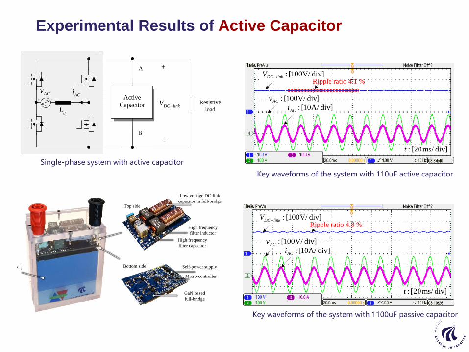
Key waveforms of the system with 110uF active capacitor
Key waveforms of the system with 1100uF passive capacitor
: [100V/ div]DC linkV
: [100V/ div]ACv
: [10A/ div]ACi
: [20ms/ div]t
Ripple ratio 4.1 %
: [100V/ div]DC linkV
: [100V/ div]ACv
: [10A/ div]ACi
: [20ms/ div]t
Ripple ratio 4.8 %
Single-phase system with active capacitor
ACv
gL
Active
Capacitor
A
Resistive
load
ACi+ -
DC linkV
+
-B
Experimental Results of Active Capacitor
Top side
Bottom sideC1 Self-power supply
Micro-controller
GaN based
full-bridge
Low voltage DC-link
capacitor in full-bridge
High frequency
filter inductor
High frequency
filter capacitor

Duality of Active Capacitor and Inductor
+
-
ihh
-vlh+vhh
(a) The active capacitor concept. (b) The proposed active inductor concept.
ilh
A
B B
A
-ilh+ihh
vhh
vlh
vAB=vmain+vhh
iAB=ilh+ihh iAB=imain+ihh
vAB=vlh+vhh
vmain+vlh
imain+ilh
Minimum apparent power ≈ Vlh × Ilh
Two-terminal active capacitor Two-terminal activeinductor
it has two terminals only same as a conventional passive components without any external feedback signal and power supply, and
the auxiliary circuit processes the minimum apparent power, which is the theoretical minimum limit.
Features:
Source: H. Wang and H. Wang, ¨A two-terminal active inductor device¨
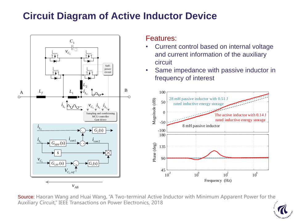
Circuit Diagram of Active Inductor Device
1L
2L
1C
1 ,C refV
-+
1Cv
+-
1(s)G
(s)HPFG
(s)LPFG
1coni2coni
1Li
2Li+
-
1Cv
2LiA
Sampling and conditioning
MCU controller
Gate driver
1Li
B
1Li1Cv2Li
ABv
2(s)G
fL
Self-
power
circuit
s
Features:• Current control based on internal voltage
and current information of the auxiliary
circuit
• Same impedance with passive inductor in
frequency of interest
Source: Haoran Wang and Huai Wang, “A Two-terminal Active Inductor with Minimum Apparent Power for the Auxiliary Circuit,” IEEE Transactions on Power Electronics, 2018
-100
-50
0
50
100
Magn
itu
de (
dB
)
10-2
100
102
104
45
90
135
180
Ph
ase
(d
eg)
Frequency (Hz)
28 mH passive inductor with 0.51 J
rated inductive energy storage
8 mH passive inductor
The active inductor with 0.14 J
rated inductive energy storage

Power Electronics devices driving the power electronics
WBG on fast move – Silicon still a player.. – base material critical
Reliability needs to be more proven for WBG
New packaging technique developed
Lower volume, higher power density, more critical
Radical change in equipment design – x10 in switching frequency
New skills are needed – eg from antenna domain
3D/4D/5D/6D design methods are necessary
Technology will develop fast – lack of models
Passive components can be a bottle-neck
Active passive components give flexibility
Curriculums have to be updated
Power Electronics and Components – Quo Vadis
16

Renewable Energy Systems

Worldwide Installed Renewable Energy Capacity (2000-2017)
1. Hydropower also includes pumped storage and mixed plants;
2. Marine energy covers tide, wave, and ocean energy
(Source: IRENA, “Renewable energy capacity statistics 2018”, http://www.irena.org/publications, March 2018)
State of the Art – Renewable Evolution
18

Global RES Annual Changes
19
Global Renewable Energy Annual Changes in Gigawatt (2001-2017)
1. Hydropower also includes pumped storage and mixed plants;
2. Marine energy covers tide, wave, and ocean energy
(Source: IRENA, “Renewable energy capacity statistics 2018”, http://www.irena.org/publications, March 2018)

Share of the Net Total Annual Additions
20
RES and non-RES as a share of the net total annual additions
Chapter 01 in Renewable energy devices and systems with simulations in MATLAB and ANSYS, Editors: F. Blaabjerg
and D.M. Ionel, CRC Press LLC, 2017
IRENA, REN 21
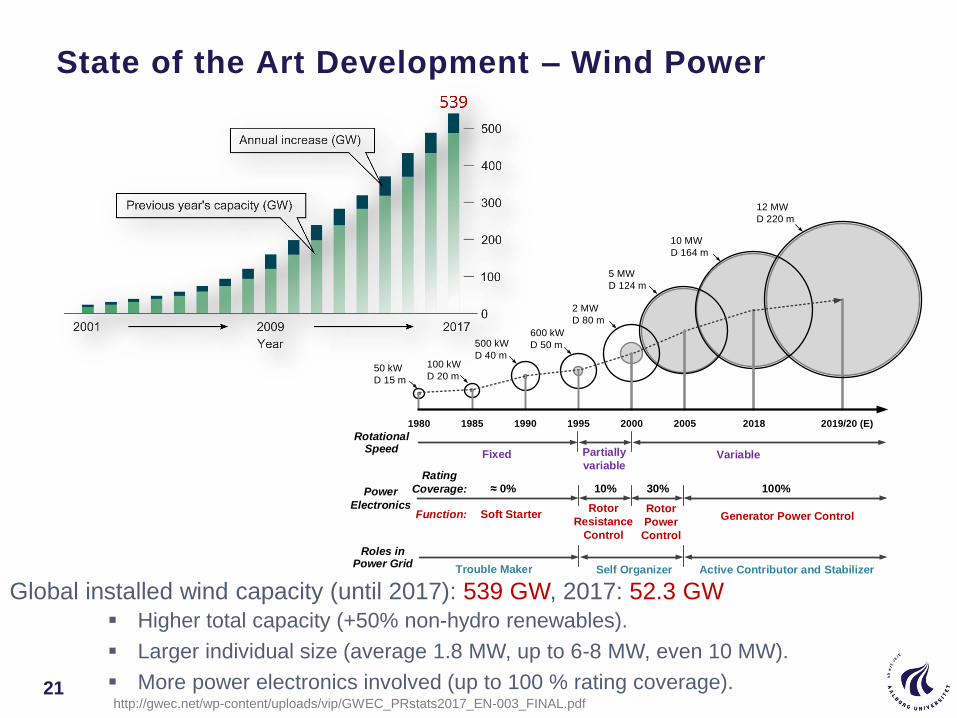
§ Higher total capacity (+50% non-hydro renewables).
§ Larger individual size (average 1.8 MW, up to 6-8 MW, even 10 MW).
§ More power electronics involved (up to 100 % rating coverage).
Global installed wind capacity (until 2017): 539 GW, 2017: 52.3 GW
State of the Art Development – Wind Power
21http://gwec.net/wp-content/uploads/vip/GWEC_PRstats2017_EN-003_FINAL.pdf
1980 1985 1990 1995 2000 2005 2018
50 kW
D 15 m
100 kW
D 20 m
500 kW
D 40 m
600 kW
D 50 m
2 MW
D 80 m
5 MW
D 124 m
10 MW
D 164 m
2019/20 (E)
12 MW
D 220 m
Soft StarterRotor
Resistance
Control
Rotor
Power
Control
Generator Power Control
0% 10% 30% 100%
Function:
Rating
Coverage:Power
Electronics
Rotational Speed
Fixed Partially
variableVariable
Roles in Power Grid
Trouble Maker Self Organizer Active Contributor and Stabilizer

DFIG: Doubly-Fed Induction Generator
PMSG: Permanent Magnet Synchronous Generator
SCIG: Squirrel-Cage Induction Generator
WRSG: Wound Rotor Synchronous Generator
Top 5 Wind Turbine Manufacturers & Technologies
22
Manufacturer Concept Rotor Diameter Power Range
Vestas (Denmark)DFIG
PMSG
90 - 120 m
105 - 162 m
2.0 - 2.2 MW
3.4 – 9.5 MW
Siemens Gamesa (Spain)
SCIG
PMSG
DFIG
154 – 167 m
120 – 142 m
114 -145 m
6.0 – 8.0 MW
3.5 – 4.3 MW
2.1 – 4.5 MW
Goldwind (China) PMSG - 2.0 – 6.0 MW
GE (USA)DFIG
PMSG
116 – 158 m
150 m
2.0 – 5.0 MW
6.0 MW
Enercon (Germany) WRSG 82 – 138 m 2.0 – 4.2 MW
Top 10 Wind Turbine Manufacturers in the World (2018); https://www.bizvibe.com/blog/top-10-wind-turbine-manufacturers-world/

State of the Art – PV Cell Technologies
23National Renewable Energy Laboratory, http://www.nrel.gov/pv/assets/images/efficiency_chart.jpg

Top 10 Solar PV Manufacturers to Watch in 2018
Damon Lapping, Top 10 Solar PV Manufacturers to Watch in 2018, https://www.disruptordaily.com/top-10-solar-pv-
manufacturers-watch-2018/24
Manufacturer Global Installation Remarks
Canadian Solar 24 GW High power output
Trina Solar 11 GW Focusing on panel efficiency
First Solar 17 GW Thin film tech
Jinko Solar 18 GW Monocrystalline tech, 23.5% η
JA Solar 23 GW
Mass production about 5 to 10 watts
above industry average, floating PV
form supplier
Sun Power Corp 18 GWResidential, commercial, utility;
Cradle to grave certified
LG Energy - Energy production from both sides
Winaico - Mono-/polycrystalline tech for harsh
conditions, e.g., salt spray
Hanwha Q Cells - Patented Q.ANTUM tech enhancing
panel energy yield in low light
Mitsubishi Electric -No lead solder, re-usable,
biodegradable materials

State of the Art Development – Photovoltaic Power
§ More significant total capacity (29 % non-hydro renewables).
§ Fastest growth rate (42 % between 2010-2015).
Global installed solar PV capacity (until 2017): 405 GW, 2017: 102 GW
SolarPower Europe, http://www.solarpowereurope.org/home/
REN21, Renewables 2016, http://www.ren21.net/wp-content/uploads/2016/10/REN21_GSR2016_FullReport_en_11.pdf
https://en.wikipedia.org/wiki/Growth_of_photovoltaics25

Top 5 PV Inverter Supplier
Global Market Share (%) of Top Five PV Inverter Suppliers by
Shipments (MWac) in 2017
Figure Adapted according to the GTM Research report
PV Europe, https://www.pveurope.eu/News/Solar-Generator/Solar-inverter-ranking-Huawei-Sungrow-and-SMA-leading26

Grid Codes for Wind Turbines
Conventional power plants provide active and reactive power, inertia
response, synchronizing power, oscillation damping, short-circuit
capability and voltage backup during faults.
Wind turbine technology differs from conventional power plants
regarding the converter-based grid interface and asynchronous
operation
Grid code requirements today
► Active power control
► Reactive power control
► Frequency control
► Steady-state operating range
► Fault ride-through capability
Wind turbines are active power plants.
27

Grid-connected PV systems ranging from several kWs to even a few
MWs are being developed very fast and will soon take a major part of
electricity generation in some areas. PV systems have to comply with
much tougher requirements than ever before.
Requirements today
► Maximize active power capture (MPPT)
► Power quality issue
► Anti Islanding
► Ancillary services for grid stability
► Communications
► High efficiency
Large-scale system
► Frequency control
► Virtual Inertia
► Fault ride-through capability
► …
Grid Codes for Photovoltaic Systems
28

PV Inverter System Configurations
29
Module Converters | String Inverter | Multi-String Inverters | Central Inverters
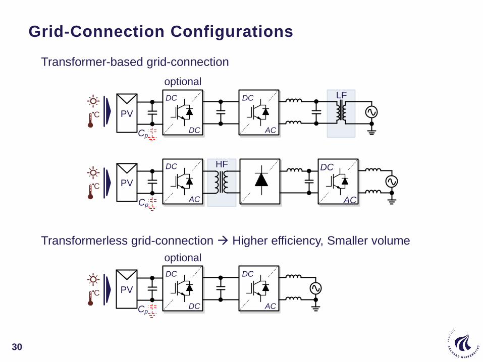
Grid-Connection Configurations
30
LF
DC
AC
DC
AC
DC
DC AC
HF
PV
PV
DC
Cp
Cp
DC
DC AC
PV
DC
Cp
optional
optional
C
C
C
Transformer-based grid-connection
Transformerless grid-connection Higher efficiency, Smaller volume
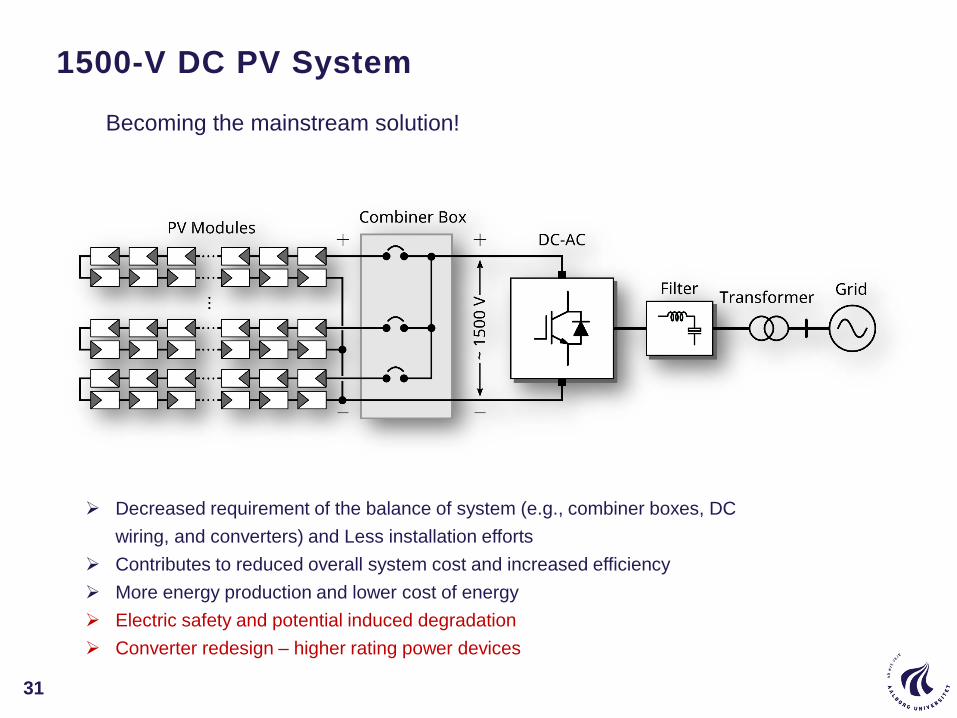
1500-V DC PV System
31
Decreased requirement of the balance of system (e.g., combiner boxes, DC
wiring, and converters) and Less installation efforts
Contributes to reduced overall system cost and increased efficiency
More energy production and lower cost of energy
Electric safety and potential induced degradation
Converter redesign – higher rating power devices
Becoming the mainstream solution!

1500-V DC PV System
32
Becoming the mainstream solution!
Sungrow five-level topology
https://www.pv-tech.org/products/abb-launches-high-power-1500-vdc-central-inverter-for-harsh-conditions
https://www.pv-tech.org/products/sungrows-1500vdc-sg125hv-string-inverter-enables-5mw-pv-power-block-designs
ABB MW Solution
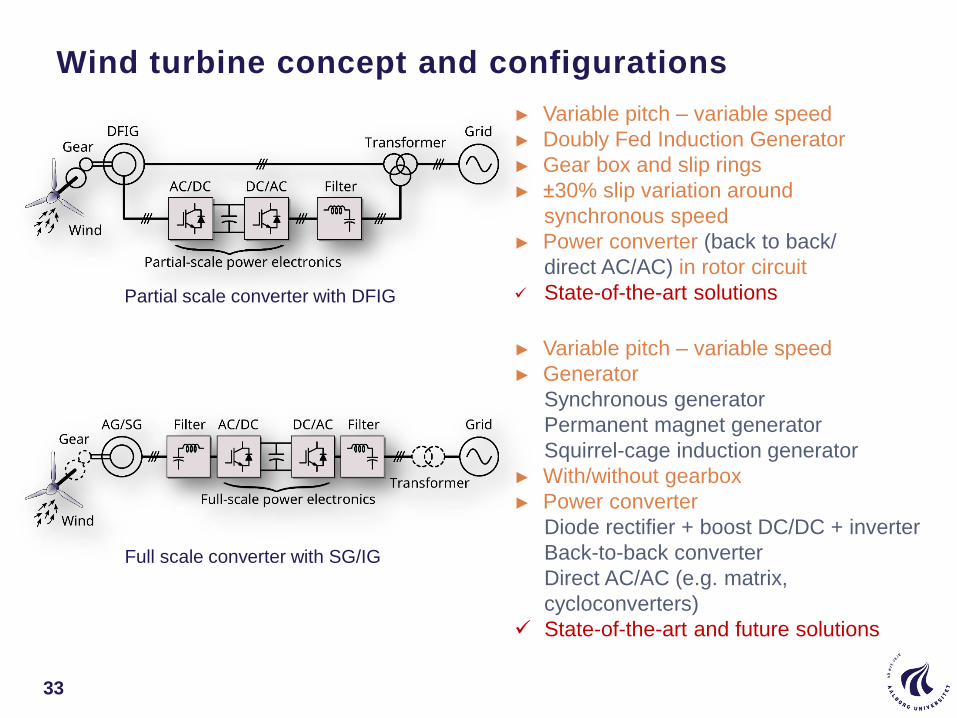
Wind turbine concept and configurations
33
► Variable pitch – variable speed
► Doubly Fed Induction Generator
► Gear box and slip rings
► ±30% slip variation around
synchronous speed
► Power converter (back to back/
direct AC/AC) in rotor circuit
State-of-the-art solutions
► Variable pitch – variable speed
► Generator
Synchronous generator
Permanent magnet generator
Squirrel-cage induction generator
► With/without gearbox
► Power converter
Diode rectifier + boost DC/DC + inverter
Back-to-back converter
Direct AC/AC (e.g. matrix,
cycloconverters)
State-of-the-art and future solutions
Partial scale converter with DFIG
Full scale converter with SG/IG

Converter topologies under low voltage (<690V)
34
Back-to-back two-level voltage source converter
§ Proven technology
§ Standard power devices (integrated)
§ Decoupling between grid and generator
(compensation for non-symmetry and other
power quality issues)
§ High dv/dt and bulky filter
§ Need for major energy-storage in DC-link
§ High power losses at high power (switching
and conduction losses) low efficiency
Transformer
2L-VSC
Filter Filter
2L-VSC
Transformer
Filter Filter
Boost
2L-VSCDiode rectifier
Generator
Diode rectifier + boost DC/DC + 2L-VSC
§ Suitable for PMSG or SG.
§ Lower cost
§ Low THD on generator, low
frequency torque pulsations in
drive train.
§ Challenge to design boost
converter at MW.
Medium voltage for large Wind Turbines seen

A 400 MW off-shore Wind Power System in Denmark
35
Anholt-DK (2016) – Ørsted

36
Wind Farm with AC and DC Power Transmission
HVAC power transmission
HVAC grid
AC
DC
DC
AC
AC
DC
DC
AC
MVAC grid
…
AC
DC
DC
AC
AC
DC
DC
AC
HVAC grid
MVAC grid
HVDC grid
…
AC
DC
DC
AC
AC
DC
DC
AC
+-
AC
DC
MVAC gridAC
DC
AC
DC
DC
AC
HVDC grid
+-
AC
DC
Solid state transformer
or DC/DC transformer
MVDC grid
HVDC power transmission
Partial-scale converter system Full-scale converter system
DC transmission grid DC distribution & transmission grid

37
Active/Reactive Power Regulation in Wind Farm
MVAC
Grid
AC
DC
DC
AC
DC
DC
AC
DC
DC
AC
DC
DC
Distributed energy storage system
Centralized energy storage system
Distributed energy storage system
DC
AC
HVAC
grid
AC
DC
DC
AC
AC
DC
DC
AC
MVAC grid
DC
AC
DC
AC
Reactive power compensator
connected to MVAC grid
Reactive power compensator
connected to HVAC grid
Advanced grid support feature achieved by power converters and controls
Local/Central storage system by batteries/supercapacitors
Reactive power compensators
§ STATCOMs/SVCs
§ Medium-voltage distribution grid/High-voltage transmission grid

38
Grid-forming & Grid-feeding Systems (examples)
PCCv*
Cv
ω*
E*
Z
Grid-forming
system
PCCi*
Ci
P*
Q* Z
Grid-feeding
system
PCC
SVM
PIdq
αβ
ud
uq
+
-
+
-
id*
iq* PI
+
-
+
-
Ed*
Eq*
abc
dq
E*
dq
abc
id
iq
id
iq
iabc
dq
abc
Ed
Eq
Eabc
d tω*
θ
θθ
θ
uα uβ
Ed
Eq
G
Load
Gen.
Current control
loop Voltage control loop
DG1PCC
SVM
PIdq
αβ
ud
uq
+
-
+
-
id*
iq*
Q*
dq
abc
id
iq
id
iq
iabc
dq
abc
Ed
Eq
Eabc
P*
θ
θ
θ
uα uβ
G
Load
Gen.
Current control
loop
Power control
loop
DG1
Ed
Ed
× ÷
÷
×
PLL θ
§ Voltage-source based inverter
§ Control reference: voltage amp. & freq.
Current-source based inverter
Control reference: active & reactive power
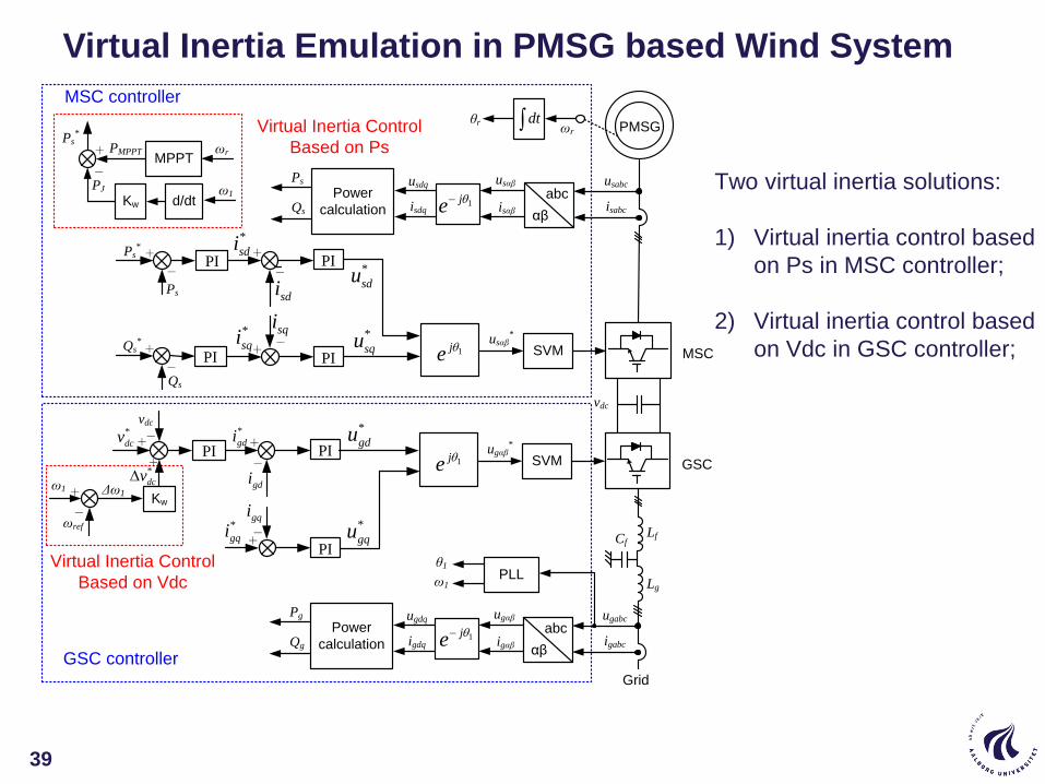
Virtual Inertia Emulation in PMSG based Wind System
GSCSVMugαβ
*
1je
abc
αβ
ugabc
igabc
ugαβ
igαβ
PLL
1je
ugdq
igdq
θ1
ω1
Grid
PI
+-
+
-
*
gdi
*
gqi
*
gdu
*
gqu
GSC controller
PI
gdi
+ -
Power
calculation
Pg
Qg
Virtual Inertia Control
Based on Vdc
PI
ωrMPPT
PMPPT
+
ω1
d/dtKw
-
PJ
Ps*
Lf
Lg
Cf
vdc
vdc*
dcv
gqi-
+
ωref
Δω1Kw
*
dcv
+
MSC
PMSGθr dt ωr
abc
αβ
usabc
isabc
usαβ
isαβ
usdq
isdq
Power
calculation
Ps
Qs
ω1
Virtual Inertia Control
Based on Ps
SVMusαβ
*
PI
+-
+
-
*
sdi
*
sqi
MSC controller
PI
sdi
sqi
+
-
Ps*
Qs*
Ps
Qs
PI
PI
+
-
1je
1je
*
sdu
*
squ
Two virtual inertia solutions:
1) Virtual inertia control based
on Ps in MSC controller;
2) Virtual inertia control based
on Vdc in GSC controller;
39

Solar power fully competitive with fossil today
Large pressure on reducing CoE for wind
WBG might reduce converter technology size and cost !?
All types of PV inverters will evolve – but not major cost in PV..
Grid codes will constant change
More intelligence into the control of renewables
Grid-feeding/Grid forming – how to do in large scale systems ?
Storage is coming into system solutions
Black start of systems (Inrush currents – how to do it)
Protection coordination in future grid
Other energy carriers will be a part of large scale system balance
Renewables 100 % competitive in 10 Years………. Power electronics is enabling
Renewable energy systems – Quo Vadis
40

Reliable Power Electronics
41
CENTER OF RELIABLE POWER ELECTRONICS, AALBORG UNIVERSITY 42
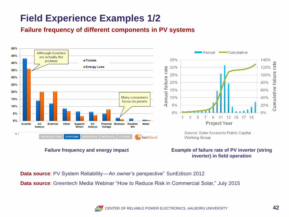
Field Experience Examples 1/2Failure frequency of different components in PV systems
Data source: PV System Reliability — An owner’s perspective” SunEdison 2012
Failure frequency and energy impact Example of failure rate of PV inverter (string
inverter) in field operation
Data source: Greentech Media Webinar “How to Reduce Risk in Commercial Solar,” July 2015

CENTER OF RELIABLE POWER ELECTRONICS, AALBORG UNIVERSITY 43
Field Experience Examples 2/2
350 onshore wind turbines in varying length of time (35,000 downtime events)
Power converter
13%
Pitch System
21.3%
Yaw
Syste
m
11.3
%
Gear b
ox 5
.1%
Others 49.3%
Power converter
18.4%
Pitch System
23.3%
Yaw
Syste
m 7
.3%
Gear b
ox 4
.7%
Others 51%
Contribution of subsystems and assemblies
to the overall failure rate of wind turbines.
Contribution of subsystems and assemblies
to the overall downtime of wind turbines.
Data source: Reliawind, Report on Wind Turbine Reliability Profiles – Field Data Reliability Analysis, 2011.
CENTER OF RELIABLE POWER ELECTRONICS, AALBORG UNIVERSITY 44
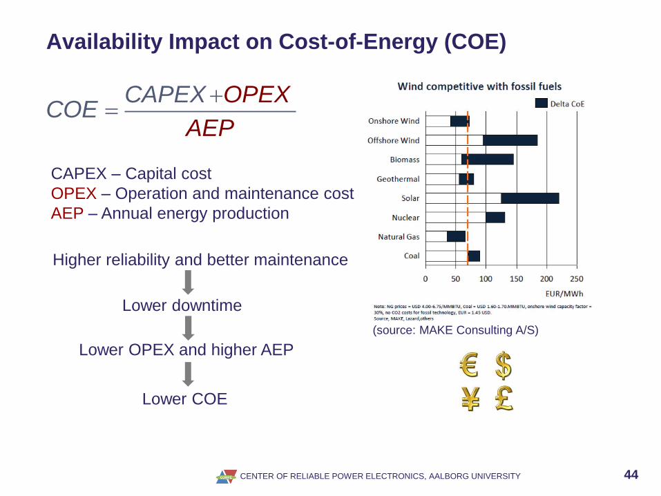
Availability Impact on Cost-of-Energy (COE)
(source: MAKE Consulting A/S)
CAPEX OPECOE
X
AEP
CAPEX – Capital cost
OPEX – Operation and maintenance cost
AEP – Annual energy production
Lower downtime
Lower OPEX and higher AEP
Higher reliability and better maintenance
Lower COE

CENTER OF RELIABLE POWER ELECTRONICS, AALBORG UNIVERSITY 45
The Reliability Challenges in Industry
Customer
expectations
Replacement if
failure
Years of warranty
Low risk of
failure
Request for
maintenance
Peace of mind
Predictive maintenance
Reliability target Affordable returns
(%) Low return rates ppm return rates
R&D approach Reliability test
Avoid catastrophes
Robustness
tests
Improve weakest
components
Design for reliability
Balance with field load
R&D key tools Product operating tests Testing at the
limits
Understanding failure
mechanisms, field load,
root cause, …
Multi-domain simulation
…
Past Present Future
Reliability at CONSTRAINED cost is a challenge

CENTER OF RELIABLE POWER ELECTRONICS, AALBORG UNIVERSITY 46
Lifetime Targets in Power Electronics Intensive
Applications
Applications Typical design target of Lifetime
Aircraft 24 years (100,000 hours flight operation)
Automotive 15 years (10,000 operating hours, 300, 000 km)
Industry motor drives 5-20 years (60,000 hours in at full load)
Railway 20-30 years (73,000 hours to 110,000 hours)
Wind turbines 20 years (120,000 hours)
Photovoltaic plants 30 years (90,000 hours to 130,000 hours)

CENTER OF RELIABLE POWER ELECTRONICS, AALBORG UNIVERSITY 47
Stress-Strength AnalysisThe essence of reliability engineering is to prevent the creation of failure
Stress or strength
Fre
qu
en
cy o
f o
ccu
ran
ce
Load distribution L Strength distribution S
Time
in ser
vice
Ideal case without
degradation
Ideal case without
degradation
Strength
degradation
with time
Failure
End-of-life
(with certain
failure rate
criterion)Failure
Extreme
load
Nominal
load
Stress analysis; Strength analysis
Stress control; Strength derating
Design at end-of-life; Consider the variations
CENTER OF RELIABLE POWER ELECTRONICS, AALBORG UNIVERSITY 48
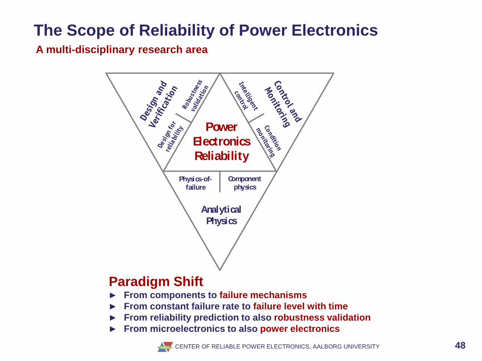
The Scope of Reliability of Power ElectronicsA multi-disciplinary research area
Analytical
Physics
Power
Electronics
Reliability
Physics-of-failure
Componentphysics
Paradigm Shift► From components to failure mechanisms
► From constant failure rate to failure level with time
► From reliability prediction to also robustness validation
► From microelectronics to also power electronics

CENTER OF RELIABLE POWER ELECTRONICS, AALBORG UNIVERSITY 49
Component-level to System-level Reliability
System reliability
metrics
· Reliability/
unreliability
· Failure rate
· Warranty period
· Bx lifetime
· Lifecycle
· Cost
· …
Reliability of
component A
Weibull (β,η)
Reliability of
component B
Normal (µ ,σ)
Reliability of
component C
Exponential (λ)
Reliability of
component D
Lognormal (µ ,σ)
Mission profile
Converter design
0.9
450 2,000 4,000 6,000 8,000 10,00000
1.0
0.8
0.6
0.4
0.2
Operation time (hour)
Re
lia
bilit
y
DC/DC converter
BoP
FC stack
FC system
Data source: S. Lee, D. Zhou, and H. Wang, "Reliability assessment of fuel cell system - A framework for
quantitative approach," in Proc. of ECCE 2016, pp. 1-5, 2016.
From Constant Failure Rate to Failure Level with Time
CENTER OF RELIABLE POWER ELECTRONICS, AALBORG UNIVERSITY 50
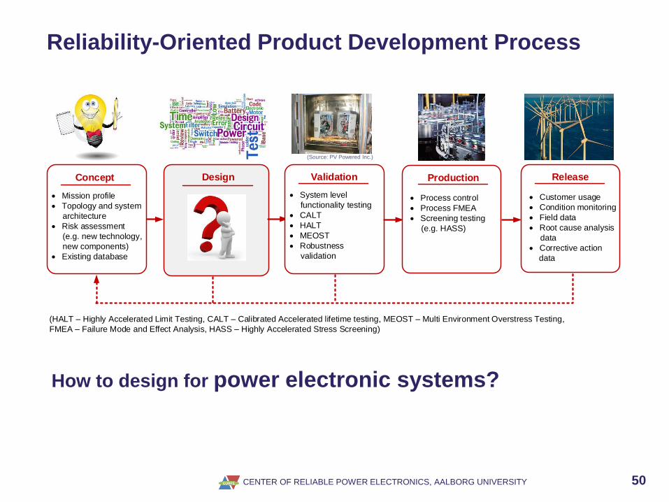
Reliability-Oriented Product Development Process
Design
?Concept
· Mission profile
· Topology and system
architecture
· Risk assessment
(e.g. new technology,
new components)
· Existing database
Validation
· System level
functionality testing
· CALT
· HALT
· MEOST
· Robustness
validation
Production
· Process control
· Process FMEA
· Screening testing
(e.g. HASS)
Release
· Customer usage
· Condition monitoring
· Field data
· Root cause analysis
data
· Corrective action
data
(HALT – Highly Accelerated Limit Testing, CALT – Calibrated Accelerated lifetime testing, MEOST – Multi Environment Overstress Testing,
FMEA – Failure Mode and Effect Analysis, HASS – Highly Accelerated Stress Screening)
(Source: PV Powered Inc.)
How to design for power electronic systems?

CENTER OF RELIABLE POWER ELECTRONICS, AALBORG UNIVERSITY 51
Design for Reliability with Artificial Intelligence - workflow
► A surrogate reliability model of converter is created
► It provides same results as detailed model, but 8 orders of magnitude faster
CENTER OF RELIABLE POWER ELECTRONICS, AALBORG UNIVERSITY 52
A mind-set change is important in power electronics circuit design –also in curricula of engineers
Physics of failure models need to be developed further
Go beyond temperature – challenge Miners rule
Models can also be used effective in condition monitoring
Reliability is also useful in service and new business
Highly need for better life time models
Highly need for smart testing methods to reduce testing time and thereby cost
IoT and other will make oceans of possibilities
Better integrated design tools to assess systems
Design automation eg. with AI
Reliable Power Electronics – Quo Vadis
52

CENTER OF RELIABLE POWER ELECTRONICS, AALBORG UNIVERSITY 53
IEEE Design Automation for Power Electronics
Power Electronic Based Power System
Stability
54

Power Electronic Based Power System Stability
Harmonic Coupling and Controller Interaction
► Multiple resonance frequencies in LCL-filters and power cables
► Dynamic coupling of multiple converters through the grid impedance
► Interactions of harmonic and inter-harmonic components - harmonic instability
LCL
LINEAR LOAD
LCL
PV
WIND
LCL
PHEV
NONLINEAR LOAD
STS
0 0.005 0.01 0.015 0.02-1.5
-1
-0.5
0
0.5
1
1.5
0 0.005 0.01 0.015 0.02-1.5
-1
-0.5
0
0.5
1
1.5
0 0.005 0.01 0.015 0.02-4
-2
0
2
4
0 0.005 0.01 0.015 0.02-1.5
-1
-0.5
0
0.5
1
1.5
0 0.005 0.01 0.015 0.02-1.5
-1
-0.5
0
0.5
1
1.5
0 0.005 0.01 0.015 0.02-1.5
-1
-0.5
0
0.5
1
1.5
GRID
CABLE
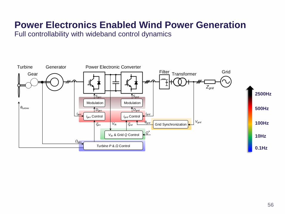
Power Electronics Enabled Wind Power Generation Full controllability with wideband control dynamics
56
0.1Hz
10Hz
100Hz
2500Hz
500Hz
Gear
GeneratorTurbine Power Electronic Converter
Modulation
Turbine P & Ω Control
igen Control
Grid Synchronization
Modulation
igrid Control igen
Vdcigen*
Vdc & Grid Q Control
Filter
igrid
igrid* θgrid
Zgrid
TransformerGrid
Ωgen
θturbineDgen
Sgen Sgrid
Dgrid
Vgrid
Q*

Modulator
DC-Bus Voltage Control
Vector Current Control
Vdc
Vdc
Phase-Locked
Loop (PLL)
iac
iac
θg
Vac
AC-Bus Voltage
Control
id iq
Vacd
Vacd
Vacd
dq
αβ
* *
*
* *
Grid-Converter Interaction Negative damping induced by converter controllers
57
Lg
Cf VgGcl iac
Zg
*
iac
YclVdc
Vg
Grid
Zg
Lf Lg
Cf
- Re{Yo}>0: stable, yet under-damped
- Re{Ycl}=0: resonant, zero damping
- Re{Ycl}<0: unstable, negative damping

Grid-Converter Interaction Mapping from control loops to instability phenomena
58
Lg
Cf VgGcl iac
Zg
*
iac
YclVdc
Vg
Grid
Zg
Lf Lg
Cf
f1: Grid fundamental frequency, fs: Switching frequency
Near-synchronous oscillations
Sub-synchronous oscillations
Harmonic oscillations
f
12f
1
fs/2
fs
Sideband (fs) oscillations
Sideband (f1)
oscillationsModulator
DC-Bus Voltage Control
Vector Current Control
Vdc
Vdc
Phase-Locked
Loop (PLL)
iac
iac
θg
Vac
AC-Bus Voltage
Control
id iq
Vacd
Vacd
Vacd
dq
αβ
* *
*
* *

Wind Power Plants - Power Electronic based Power SystemsCross-frequency coupling and interactions
59
Abnormal harmonics due to converter
control interactions
Resonance propagation through
power cables and filters
Unstable oscillations with weak power
grids, either low short-circuit ratio
(SCR) or low inertia, e.g. HVDC.
Grid
0 0.005 0.01 0.015 0.02-1.5
-1
-0.5
0
0.5
1
1.5
0 0.005 0.01 0.015 0.02-1.5
-1
-0.5
0
0.5
1
1.5
0 0.005 0.01 0.015 0.02-1.5
-1
-0.5
0
0.5
1
1.5
0 0.005 0.01 0.015 0.02-1.5
-1
-0.5
0
0.5
1
1.5
Transformer
Cable
Wind Turbine

CENTER OF RELIABLE POWER ELECTRONICS, AALBORG UNIVERSITY 60
Challenges - From Power Electronics to Power Systems
60
Po
wer
Ele
ctro
nic
co
mp
on
en
ts a
nd
co
nve
rters
Po
wer
Ele
ctro
nic
s b
ase
d P
ow
er
Sys
tem
s
State-of-the art
methods are NOTScalable to power system level
■ Power electronic apparatus degradation (reliability) could turn a stable system to an unstable system
■ Abnormal operation (including instability issues) could stress more the power electronic apparatus
■ New components and new mission profiles in power systems

We are facing a power electronics based power system
Technical risk of less availability of energy in power system
Analysis tools are evolving – but a challenge
Different vendors might challenge system stability
Need of analysis tools to map all uncertainties – both power electronics and power systems
Need of new testing methods to analyze thousands of power converters operating at the same time
How to aggregate from converter to complex systems with 1000’s of units
Reliability assessment methods of complex systems
Grid structure might be changing
Power Electronic Based Power System Stability – Quo Vadis
61

Outlook
62

Electricity creates the modern (and efficient) world
Power Electronics – key technology for modern society – super scaling
Cost of Energy go more down incl low failure-rate in renewables –
Paradigm shift in power system operation with renewables and storage
WBG will radical change power circuit design – few new power converters will be invented…
Components need to be further developed – and modelled
Passive components are a challenge
Reliability engineering continue its development – complex
Better reliability – more income on service for manufacturers
Stability issues in solid state based power grid as well as conventional power system
More stringent grid codes will still be developed – new demands
Electrification of transportation – the large application for next two decades
AI can assist in design, control and condition monitoring
Rewrite our curriculums
And much more..
Power Electronics Technology – Summary
63

Acknowledgment
64
Dr. Yongheng Yang, Dr. Xiongfei Wang, Dr.
Dao Zhou, Dr. Tomislav Dragicevic, Dr. Huai
Wang
from Department of Energy Technology
Aalborg University
Look at
www.et.aau.dk
www.corpe.et.aau.dk
www.harmony.et.aau.dk
www.repeps.aau.dk


Thank you for your attention!
Aalborg University
Department of Energy Technology
Aalborg, Denmark

References
67
1. M. Liserre, R. Cardenas, M. Molinas, J. Rodriguez, ”Overview of Multi-MW wind turbines and wind parks”, IEEE Trans. on Industrial
Electronics, Vol. 58, No. 4, pp. 1081-1095, April 2011.
2. REN21 - Renewables 2014 Global Status Report, June, 2014. (Available: http://www.ren21.net)
3. Z. Chen, J.M. Guerrero, F. Blaabjerg, "A Review of the State of the Art of Power Electronics for Wind Turbines," IEEE Trans. on Power
Electronics, vol.24, No.8, pp.1859-1875, Aug 2009.
4. F. Blaabjerg, Z. Chen, S.B. Kjaer, “Power Electronics as Efficient Interface in Dispersed Power Generation Systems”, IEEE Trans. on
Power Electronics, Vol. 19, no. 4, pp. 1184-1194, 2004.
5. A.D. Hansen, F. Iov, F. Blaabjerg, L.H. Hansen, “Review of contemporary wind turbine concepts and their market penetration,” Journal of
Wind Engineering, Vol. 28, No. 3, pp. 247-263, 2004.
6. M.P. Kazmierkowski, R. Krishnan, F. Blaabjerg, Control in Power Electronics-Selected problems, Academic Press, 2002. ISBN 0-12-
402772-5.
7. F. Blaabjerg, M. Liserre, K. Ma, “Power Electronics Converters for Wind Turbine Systems,” IEEE Trans. on Industry Application, vol. 48,
no. 2, pp. 708-719, 2012.
8. F. Blaabjerg, K. Ma, “Future on power electronics for wind turbine systems,” IEEE Journal of Emerging and Selected Topics in Power
Electronics, vol. 1, no. 3, pp. 139-152, 2013.
9. H. Wang, M. Liserre, F. Blaabjerg, P. P. Rimmen, J. B. Jacobsen, T. Kvisgaard, J. Landkildehus, "Transitioning to physics-of-failure as a
reliability driver in power electronics," IEEE Journal of Emerging and Selected Topics in Power Electronics, Vol. 2, No. 1, pp.97-114, 2014.
10. H. Wang, M. Liserre, and F. Blaabjerg, “Toward reliable power electronics - challenges, design tools and opportunities,” IEEE Industrial
Electronics Magazine, vol.7, no. 2, pp. 17-26, Jun. 2013.
11. S. B. Kjaer, J. K. Pedersen, and F. Blaabjerg, “A review of single-phase grid connected inverters for photovoltaic modules,” IEEE Trans.
on Ind. Appl., vol. 41, no. 5, pp. 1292-1306, Sep. 2005.
12. K. Ma, F. Blaabjerg, and M. Liserre, “Thermal analysis of multilevel grid side converters for 10 MW wind turbines under low voltage ride
through”, IEEE Trans. Ind. Appl., vol. 49, no. 2, pp. 909-921, Mar./Apr. 2013.
13. K. Ma, M. Liserre, and F. Blaabjerg, “Reactive power influence on the thermal cycling of multi-MW wind power inverter”, IEEE Trans. on
Ind. Appl., vol. 49, no. 2, pp. 922-930, Mar./Apr. 2013.
14. C. Busca, R. Teodorescu, F. Blaabjerg, S. Munk-Nielsen, L. Helle, T. Abeyasekera, and P. Rodriguez, “An overview of the reliability
prediction related aspects of high power IGBTs in wind power applications,” Journal of Microelectronics Reliability, vol. 51, no. 9-11, pp.
1903-1907, 2011.
15. E. Koutroulis and F. Blaabjerg, “Design optimization of transformerless grid-connected PV inverters including reliability,” IEEE Trans. on
Power Electronics, vol. 28, no. 1, pp. 325-335, Jan. 2013.
16. K. B. Pedersen and K. Pedersen, “Bond wire lift-off in IGBT modules due to thermo-mechanical induced stress,” in Proc. of PEDG’ 2012,
pp. 519 - 526, 2012.

References
68
17. S. Yang, D. Xiang, A. Bryant, P. Mawby, L. Ran and P. Tavner, “Condition monitoring for device reliability in power electronic converters: a
review,” IEEE Trans. Power Electron., vol. 25, no. 11, pp. 2734-2752, Nov., 2010.
18. M. Pecht and J. Gu, “Physics-of-failure-based prognostics for electronic products,” Trans. of the Institute of Measurement and Control ,
vol. 31, no. 3-4, pp. 309-322, Mar./Apr., 2009.
19. Moore, L. M. and H. N. Post, “Five years of operating experience at a large, utility-scale photovoltaic generating plant,” Progress in
Photovoltaics: Research and Applications 16(3): 249-259, 2008.
20. Reliawind, Report on Wind Turbine Reliability Profiles – Field Data Reliability Analysis, 2011.
21. D. L. Blackburn, “Temperature measurements of semiconductor devices - a review,” in Proc. IEEE Semiconductor Thermal Measurement
and Management Symposium, pp. 70-80, 2004.
22. A. Bryant, S. Yang, P. Mawby, D. Xiang, Li Ran, P. Tavner, P. Palmer, "Investigation Into IGBT dV/dt During Turn-Off and Its Temperature
Dependence", IEEE Trans. Power Electron., vol.26, no.10, pp.3019-3031, Oct. 2011.
23. Z. Xu, D. Jiang, M. Li, P. Ning, F.F. Wang, Z. Liang, "Development of Si IGBT Phase-Leg Modules for Operation at 200 °C in Hybrid
Electric Vehicle Applications", IEEE Trans. Power Electron., vol.28, no.12, pp.5557-5567, Dec. 2013.
24. H. Chen, V. Pickert, D. J. Atkinson, and L. S. Pritchard, “On-line monitoring of the MOSFET device junction temperature by computation of
the threshold voltage,” in Proc. 3rd IET Int. Conf. Power Electron. Mach. Drives, Dublin, Ireland, Apr. 4–6, 2006, pp. 440–444.
25. D. Barlini, M. Ciappa, M. Mermet-Guyennet, and W. Fichtner, “Measurement of the transient junction temperature in MOSFET devices
under operating conditions,” Microelectron. Reliabil., vol. 47, pp. 1707–1712, 2007.
26. A. Isidori, F. M. Rossi, F. Blaabjerg, and K. Ma, "Thermal loading and reliability of 10 MW multilevel wind power converter at different wind
roughness classes", IEEE Trans. on Industry Applications, vol. 50, no. 1, pp. 484-494, 2014.
27. K. B. Pedersen, D. Benning, P. K. Kristensen, V.Popok, and K. Pedersen, "Interface structure and strength of ultrasonically wedge bonded
heavy aluminium wires in Si-based power modules," Journal of Materials Science: Materials in Electronics, Apr 2014.
28. K. Ma, A. S. Bahman, S. M. Beczkowski, F. Blaabjerg, “Complete Loss and Thermal Model of Power Semiconductors Including Device
Rating Information,” IEEE Trans. on Power Electronics, Vol. 30, No. 5, pp. 2556-2569, May 2015.
29. K. Ma, W. Chen, M. Liserre, F. Blaabjerg, “Power Controllability of Three-phase Converter with Unbalanced AC Source”, IEEE Trans. on
Power Electronics, Vol. 30, No. 3, pp. 1591-1604, Mar 2014.
30. K. Ma, M. Liserre, F. Blaabjerg, T. Kerekes, “Thermal Loading and Lifetime Estimation for Power Device Considering Mission Profiles in
Wind Power Converter,” IEEE Trans. on Power Electronics, Vol. 30, No. 2, pp. 590-602, 2015.
31. U. M. Choi, K. B. Lee, F. Blaabjerg, "Diagnosis and tolerant strategy of an open-switch fault for T-type three-level inverter systems," IEEE
Transactions on Industry Applications, vol. 50, no. 1, pp. 495-508, 2014.
32. Y. Yang, Huai Wang, Frede Blaabjerg, and Tamas Kerekes, “A hybrid power control concept for PV inverters with reduced thermal
loading,” IEEE Trans. Power Electron., Vol.29, No. 12, pp.6271-6275, 2014.
References
69
33. M. Liserre, F. Blaabjerg, and S. Hansen, “Design and Control of an LCL-Filter-Based Three-Phase Active Rectifier,” IEEE Trans. Ind.
Appl., vol. 41, no. 5, pp. 1281–1291, Sep. 2005.
34. L. Wei and R.A. Lukaszewski, “Optimization of the Main Inductor in a LCL Filter for Three Phase Active Rectifier”, 42nd IAS Annual
Meeting. Conference Record of the 2007 IEEE Industry Applications Conference, 2007, vol., no., pp.1816,1822, 23-27 Sept. 2007
35. J. Muhlethaler, M. Schweizer, R. Blattmann, J. W. Kolar, and A. Ecklebe, “Optimal Design of LCL Harmonic Filters for Three-Phase PFC
Rectifiers,” IEEE Trans. Power Electron., vol. 28, no. 7, pp. 3114–3125, Jul. 2013.
36. IEEE Application Guide for IEEE Std 1547™, IEEE Standard for Interconnecting Distributed Resources with Electric Power Systems
(2008)
37. “Generating plants connected to the medium voltage network - Guideline for generating plants connection to and parallel operation with
the medium voltage network”, BDEW Bundesverband der Energie- und Wasserwirtschaft e.V. Reinhardtstraße 32, 10117 Berlin (2008)
38. VDE-AR-N 4105: Generators connected to the low-voltage distribution network - Technical requirements for the connection to and parallel
operation with low-voltage distribution network (2010)
39. R. D. Middlebrook, “Design Techniques for Preventing Input-Filter Oscillations in Switched-Mode Regulators,” Proc. Power Convers.
Conf., 1978, pp. A3.1–A3.16.
40. Beres, R.N.; Xiongfei Wang; Blaabjerg, F.; Bak, C.L.; Liserre, M., "New optimal design method for trap damping sections in grid-connected
LCL filters," Energy Conversion Congress and Exposition (ECCE), 2014 IEEE , vol., no., pp.3620,3627, 14-18 Sept. 2014.
41. X. Wang, Y. W. Li, F. Blaabjerg, and P. C. Loh, “Virtual-impedance-based control for voltage-source and current-source converters," IEEE
Transactions on Power Electronics (Early Access Article, DOI: 10.1109/TPEL.2014.2382565).
42. X. Wang, F. Blaabjerg, and P. C. Loh, “Virtual RC damping of LCL-filtered voltage source converters with extended selective harmonic
compensation,” IEEE Transactions on Power Electronics (Early Access Article, DOI: 10.1109/TPEL.2014.2361853).
43. X. Wang, F. Blaabjerg, and P. C. Loh, “Grid-current-feedback active damping for LCL resonance in grid-connected voltage source
converters,” IEEE Transactions on Power Electronics (Early Access Article, DOI: 10.1109/TPEL.2015.2411851).
44. Y. Yang, H. Wang, and F. Blaabjerg, "Reduced junction temperature control during low-voltage ride-through for single-phase photovoltaic
inverters,“ IET Power Electronics, pp. 1-10, 2014.
45. D. Zhou, F. Blaabjerg, M. Lau, and M. Tonnes, "Thermal cycling overview of multi-megawatt two-level wind power converter at full grid
code operation", IEEJ Journal of Industry Applications, vol.2, no.4 pp.173–182, 2013.
46. K. B. Pedersen, P. K. Kristensen, V. Popok, and K. Pedersen, "Micro-sectioning approach for quality and reliability assessment of wire
bonding interfaces in IGBT modules", Microelectronics Reliability, Vol. 53, no. 9-11, pp. 1422–1426, Sep 2013.
47. K. Ma, F. Blaabjerg "Thermal optimized modulation method of three-level NPC inverter for 10 MW wind turbines under low voltage ride
through", IET Journal on Power Electronics, vol. 5, no. 6, pp. 920-927, Jul 2012.
48. R. Wu, F. Blaabjerg, H. Wang, and M. Liserre, "Overview of catastrophic failures of freewheeling diodes in power electronic circuits",
Microelectronics Reliability, Vol. 53, no. 9–11, Pages 1788–1792, Sep 2013.
References
70
48. F. Blaabjerg and K. Ma, "Wind Energy Systems," in Proceedings of the IEEE, vol. 105, no. 11, pp. 2116-2131, Nov. 2017.
doi: 10.1109/JPROC.2017.2695485
Open Access : URL: http://ieeexplore.ieee.org/stamp/stamp.jsp?tp=&arnumber=7927779&isnumber=8074545
49. F. Blaabjerg, Y. Yang, D. Yang and X. Wang, "Distributed Power-Generation Systems and Protection," in Proceedings of the IEEE,
vol. 105, no. 7, pp. 1311-1331, July 2017. doi: 10.1109/JPROC.2017.2696878
Open Access : URL: http://ieeexplore.ieee.org/stamp/stamp.jsp?tp=&arnumber=7926394&isnumber=7951054

References (Harmonic Stability)
1. X. Wang and F. Blaabjerg, “Harmonic stability in power electronic based power systems: concept, modeling, and analysis,” IEEE Trans. Smart Grid, Early Access, 2018.
2. X. Wang, F. Blaabjerg, and W. Wu, “Modeling and analysis of harmonic stability in ac power-electronics-based power system,” IEEE Trans. Power Electron., vol. 29, no. 12, pp. 6421-6432,
Dec. 2014.
3. X. Wang, L. Harnefors, and F. Blaabjerg, “Unified impedance model of grid-connected voltage-source converters," IEEE Trans. Power Electron., vol. 33, no. 2, pp. 1775-1787, Feb. 2018.
4. X. Wang, F. Blaabjerg, and P. C. Loh, “Passivity-based stability analysis and damping injection for multiparalleled VSCs with LCL filters,” IEEE Trans. Power Electron., vol. 32, no. 11, pp.
8922-8935, Nov. 2017.
5. Y. Wang, X. Wang, F. Blaabjerg, and Z. Chen, "Small-signal stability analysis of inverter-fed power systems using component connection method," IEEE Trans. Smart Grid, Early Access,
2018.
6. M. Lu, X. Wang, P. C. Loh, and F. Blaabjerg, “Resonance interaction of multi-parallel grid-connected inverters with LCL filter,” IEEE Trans. Power Electron., vol. 32, no. 2, pp. 894-899, Feb.
2017.
7. J. Kwon, X. Wang, F. Blaabjerg, C. L. Bak, A. R. Wood and N. R. Watson, “Harmonic instability analysis of single-phase grid connected converter using harmonic state space (HSS) modeling
method”, IEEE Trans. Ind. Appl.,, Vol. 52, No. 5, pp. 4188 – 4200. Sept./Oct. 2016.
8. L. Harnefors, X. Wang, A. G. Yepes, and F. Blaabjerg, “Passivity-based stability assessment of grid-connected VSCs – an overview,” IEEE J. Emerg. Sel. Topics Power Electron., vol. 4, no.
1, pp. 116-125, Mar. 2016.
9. L. Harnefors, “Modeling of three-phase dynamic systems using complex transfer functions and transfer matrices,” IEEE Trans. Ind. Electron. vol. 54, no. 4, pp. 2239-2248, Aug. 2007.
10. L. Harnefors, L. Zhang, and M. Bongiorno, “Frequency-domain passivity-based current controller design,” IET Power Electron., vol. 1, no. 4, pp. 455-465, Dec. 2008.
11. J. Kwon, X. Wang, F. Blaabjerg, C. L. Bak, A. R. Wood, and N. Watson, “Linearized modeling methods of ac-dc converters for an accurate frequency response,” IEEE J. Emerg. Sel. Topics
Power Electron., vol. 5, no. 4, pp. 1526-1541, Dec. 2017.
12. R. D. Middlebrook, “Predicting modulator phase lag in pwm converter feedback loop,” Powercon 1981, pp. 1-6.
13. R. D. Middlebrook and S. Cuk, “A general unified approach to modeling switching-converter power systems,” in Proc. IEEE PESC 1976, pp. 73-86.
14. K. D. Ngo. “Low frequency characterization of PWM converters,” IEEE Trans. Power Electron., vol. PE-1, no. 4, pp. 223-230, Oct. 1986.
15. X. Wang, Y. W. Li, F. Blaabjerg, and P. C. Loh, “Virtual-impedance-based control for voltage- and current-source converters,” IEEE Trans. Power Electron. vol. 30, no. 12, pp. 7019-7037,
Dec. 2015.
16. X. Wang, F. Blaabjerg, Y. Pang, P. C. Loh, “A series-LC-filtered active damper with grid disturbance rejection for ac power-electronics-based power systems,” IEEE Trans. Power Electron.
vol. 30, no. 8, pp. 4037-4041, Aug. 2015.
17. B. Ferreira, "Understanding the Challenges of Converter Networks and Systems: Better opportunities in the future," IEEE Power Electronics Mag., vol. 3, no. 2, pp. 46-49, Jun. 2016.
18. B. Kroposki, et al., “Achieving a 100% renewable grid: operating electric power systems with extremely high levels of variable renewable energy,” IEEE Power & Energy Mag. vol. 15, no. 2,
pp. 61-73, Mar./Apr. 2017.
CENTER OF RELIABLE POWER ELECTRONICS, AALBORG UNIVERSITY 72
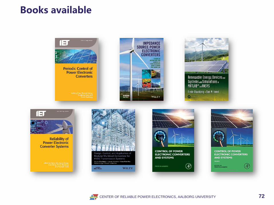
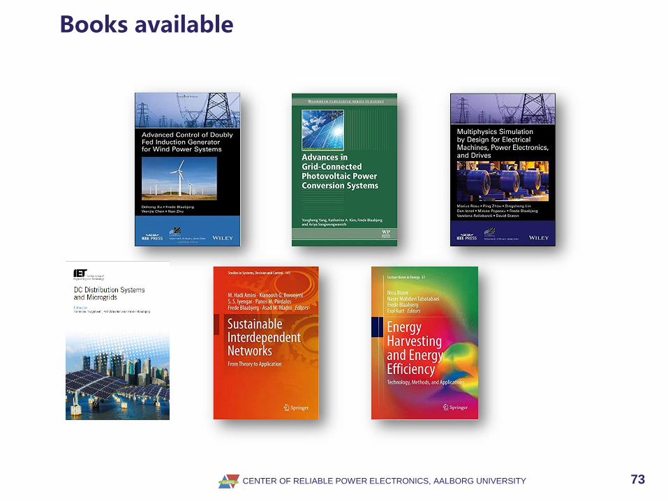
Books available
CENTER OF RELIABLE POWER ELECTRONICS, AALBORG UNIVERSITY 73
Books available


