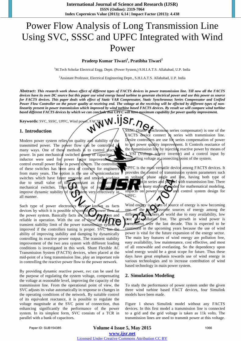
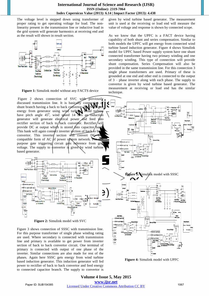
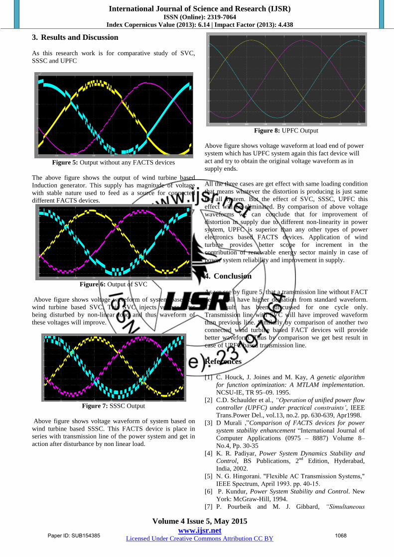
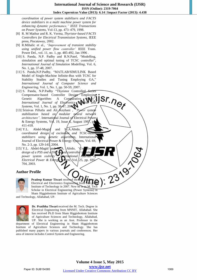
International Journal of Science and Research (IJSR) ISSN (Online): 2319-7064 Index Copernicus Value (2013): 6.14 | Impact Factor (2013): 4.438 Volume 4 Issue 5, May 2015 www.ijsr.net Licensed Under Creative Commons Attribution CC BY Power Flow Analysis of Long Transmission Line Using SVC, SSSC and UPFC Integrated with Wind Power Pradeep Kumar Tiwari 1 , Pratibha Tiwari 2 1 M.Tech Scholar Electrical Engg. Deptt. (Power System,) S.H.I.A.T.S. Allahabad, U.P. India 2 Assistant Professor, Electrical Engineering Deptt., S.H.I.A.T.S. Allahabad, U.P. India Abstract: This research work shows effect of different types of FACTS devices in power transmission line. Till now all the FACTS devices have its own DC source but this paper use wind energy based turbine to generate electrical power and use this power as source for FACTS devices. This paper deals with effect of Static VAR Compensator, Static Synchronous Series Compensator and Unified Power Flow Controller on the power quality at receiving end. The voltage at the receiving will be effected by different types of non- linearity present in power transmission which improved by wind turbine based FACTS devices. By result we will compare wind turbine based different FACTS devices by which we can conclude that UPFC will have maximum capability for power quality improvement. Keywords: SVC, SSSC, UPFC, Wind power, FACTS 1. Introduction Modern power system relies on quality and stability of the transmitted power. The power flow can be controlled in many ways. One of these methods is to control reactive power. In past mechanical switched group of capacitor and inductor were used for power factor improvement and control overall power flow in power system. The controlling of these switches has been area of concern for engineers from many years. The option is the use of semiconductor switches which have faster response and smooth working due to small value of time constant as compared to mechanical switches. Thus these type of switches can improve dynamic stability of the system very effectively in all manner. Such type of power electronics device known as facts devices by which it is possible to control the power flow of the power system. Basically facts are fast in operation and reliable in operation. With the use of these devices. The transient stability limit of the power transmission system is improved if the controllers tuning is proper. SVC has the ability of improving stability and damping by dynamically controlling its reactive power output. The transient stability improvement of the two area system with different loading conditions is investigated in this work. Shunt Flexible AC Transmission System (FACTS) devices, when placed at the mid-point of a long transmission line, play an important role in controlling the reactive power flow to the power network. By providing dynamic reactive power, svc can be used for the purpose of regulating the system voltage, compensating the voltage at reasonable level, improving the capacity of the transmission line. From the operational point of view, the SVC adjusts its value automatically in response to changes in the operating conditions of the network. By suitable control of its equivalent reactance, it is possible to regulate the voltage magnitude at the SVC point of connection, thus enhancing significantly the performance of the power system. In its simplest form, SVC consists of a TCR in parallel with a bank of capacitors. SSSC (Static synchronous series compensator) is one of the FACTS device connect in series with transmission line. Desire controllers are use for series compensation of power to get power quality improvement. It Controls reactance of the transmission line by injecting reactive power by means of a VSI (Voltage source inverter) and a control input by controlling voltage at connecting point of the system. UPFC is the most versatile device among FACTS devices. It provides the control of transmission system parameters such as voltage, phase angle and line, having both type of connection in series and parallel with transmission line. There have been many studies intended for mathematical modeling, impacts on power systems and control system design for UPFC. Wind energy is a form of source of energy is now becoming one of the most favorite sources of energy among the different researchers in world due to easy availability, low cost and pollution free. The growth in wind power is tremendous over the last decade. This is expected to be continued in the upcoming years because the use of wind power is vital for the future expansion of the energy sector. The main key features of wind energy are pollution free, easy availability, low maintenance, cost effective, and most of all renewable and everlasting. So the dependency upon wind energy would be a great scope for future. Thus these days have great emphasis towards use of wind energy in various technologies and to increase contribution of wind based technology in main power system. 2. Simulation Modeling To study the performance of power system under the given three wind turbine based FACT devices, four Simulink models have been made. Figure 1 shows Simulink model without any FACTS devices. In this first model a transmission line is connected to a grid and the grid voltage is taken as 11k volts. The transmission lines are used to transmit power at this voltage. Paper ID: SUB154385 1066
Transcript
International Journal of Science and Research (IJSR) ISSN (Online): 2319-7064
Index Copernicus Value (2013): 6.14 | Impact Factor (2013): 4.438
Volume 4 Issue 5, May 2015
www.ijsr.net Licensed Under Creative Commons Attribution CC BY


![A New Hybrid UPFC Controller for Power Flow Control and ...downloads.hindawi.com/archive/2017/7873491.pdf · the UPFC control system [1, 28, 29]. The DC-link voltage varies when 𝑃](https://static.documents.pub/doc/80x56/5f726899e9f94b1761380a29/a-new-hybrid-upfc-controller-for-power-flow-control-and-the-upfc-control-system.jpg)
