POWER LINE COMMUNICATION APPLIED TO FLIGHT TEST INSTRUMENTATION Moises V. Ribeiro 1,2 , Fabrício P. V. de Campos 1,2 , Stéfano A. Souza 1 , Ândrei Camponogara 2 , Elisa S. B. de Castro 3 , Lucas M. C. S. Evangelista 3 , Sérgio D. Penna 3 1 Smarti9 Ltd. , 2 Federal University of Juiz de Fora (UFJF) and 3 Embraer S.A. Keywords: Channel characterization, sounding, power line communication, aircraft. Abstract This paper investigates the usefulness of the power line communication (PLC) technology for assisting the data communication demands re- lated to flight test aircraft. In this way, statisti- cal analyses of the average channel attenuation, the coherence bandwidth, the root mean squared delay spread, and the ergodic achievable rate of the electric power grids used by flight test air- craft are discussed. Also, a PLC modem proto- type designed to operate in flight test aircraft is presented. Numerical results show that PLC sys- tems in a peer-to-peer configuration can reach up to 306.33 Mbps, free of packet losses. 1 Introduction Power line communication (PLC) applications have been widely studied for indoor (residen- tial and commercial buildings) and outdoor elec- tric power grids [1, 2]. Recently, PLC sys- tems applied to in-vehicle environment, such as cars, ships, trains, spacecrafts, and aircraft have attracted interesting more interested due to the feasibility of PLC systems to fulfill several data communication demands and constraints in these environment (i.e., ubiquitousness, redun- dancy, weigthing reduction and cabling installa- tion cost). One the other hand, it is well-established that electric power grids were not specified and de- signed for data communication purposes. In fact, in such media the transmitted signals can suf- fer significant attenuation due to the distance and frequency increases, the impedance mismatch- ings and be considerable corrupted due to the presence of high impulsive noises. Aiming to study this harsh data communication environ- ment, there are several contributions focusing on the measurement and the characterization of in- home and outdoor electric power grids [3, 4] and reference therein. However, these studies do not addresses the aircraft electric power network, in which the geometrical characteristics and tree- shaped topologies of cable bundles and the de- sign of electric circuits are completely different from in-home and outdoor electric power grids [5]. In order to verify the viability of PLC in air- craft some studies have characterized the aircraft power network. [6–9]. Relevant is to mention that the measurements of fourteen PLC chan- nels and the characterization of their channel fre- quency responses (CFRs) magnitude on a test bench of a cabin lighting system (CLS) cell were addressed in [8]. Also, [6] discussed about the coherence bandwidth and the delay spread (DS). Based on the fact that limited research re- sults about PLC systems for aircraft are found in the literature, this paper focuses on the measure- ment and statistical characterization of the air- craft power network that delivers energy to flight test instrumentation equipment. In addition, it discussed the prototype of a PLC modem, which was designed based on the a priori measurement and characterization of electric power network for flight test intrumentation. In this way, the 1
Transcript
POWER LINE COMMUNICATION APPLIED TO FLIGHT TESTINSTRUMENTATION
Moises V. Ribeiro1,2 , Fabrício P. V. de Campos1,2 , Stéfano A. Souza1 , Ândrei Camponogara2
, Elisa S. B. de Castro3 , Lucas M. C. S. Evangelista3 , Sérgio D. Penna3
1Smarti9 Ltd. , 2Federal University of Juiz de Fora (UFJF) and 3Embraer S.A.
Keywords: Channel characterization, sounding, power line communication, aircraft.
Abstract
This paper investigates the usefulness of thepower line communication (PLC) technology forassisting the data communication demands re-lated to flight test aircraft. In this way, statisti-cal analyses of the average channel attenuation,the coherence bandwidth, the root mean squareddelay spread, and the ergodic achievable rate ofthe electric power grids used by flight test air-craft are discussed. Also, a PLC modem proto-type designed to operate in flight test aircraft ispresented. Numerical results show that PLC sys-tems in a peer-to-peer configuration can reach upto 306.33 Mbps, free of packet losses.
1 Introduction
Power line communication (PLC) applicationshave been widely studied for indoor (residen-tial and commercial buildings) and outdoor elec-tric power grids [1, 2]. Recently, PLC sys-tems applied to in-vehicle environment, suchas cars, ships, trains, spacecrafts, and aircrafthave attracted interesting more interested due tothe feasibility of PLC systems to fulfill severaldata communication demands and constraints inthese environment (i.e., ubiquitousness, redun-dancy, weigthing reduction and cabling installa-tion cost).
One the other hand, it is well-established thatelectric power grids were not specified and de-signed for data communication purposes. In fact,in such media the transmitted signals can suf-
fer significant attenuation due to the distance andfrequency increases, the impedance mismatch-ings and be considerable corrupted due to thepresence of high impulsive noises. Aiming tostudy this harsh data communication environ-ment, there are several contributions focusing onthe measurement and the characterization of in-home and outdoor electric power grids [3, 4] andreference therein. However, these studies do notaddresses the aircraft electric power network, inwhich the geometrical characteristics and tree-shaped topologies of cable bundles and the de-sign of electric circuits are completely differentfrom in-home and outdoor electric power grids[5].
In order to verify the viability of PLC in air-craft some studies have characterized the aircraftpower network. [6–9]. Relevant is to mentionthat the measurements of fourteen PLC chan-nels and the characterization of their channel fre-quency responses (CFRs) magnitude on a testbench of a cabin lighting system (CLS) cell wereaddressed in [8]. Also, [6] discussed about thecoherence bandwidth and the delay spread (DS).
Based on the fact that limited research re-sults about PLC systems for aircraft are found inthe literature, this paper focuses on the measure-ment and statistical characterization of the air-craft power network that delivers energy to flighttest instrumentation equipment. In addition, itdiscussed the prototype of a PLC modem, whichwas designed based on the a priori measurementand characterization of electric power networkfor flight test intrumentation. In this way, the
1
MOISES V. RIBEIRO
main contributions of our work are summarizedas follows:
• A measurement campaign performed at abusiness jet test prototype, specifically onthe power network that deliveries energyfor instrumentation equipment of flighttests covering the frequency band 1.7 −86 MHz.
• Statistical analyses of the average channelattenuation (ACA), the coherence band-width (CB), the root mean squared delayspread (RMS-DS), and the ergodic achiev-able data rate.
• A presentation of a prototype of PLC mo-dem that is capable of reaching up to306.33 Mbps, free of packet losses, at thelevel of transport layer by using the userdatagram protocol (UDP) protocol.
This paper is organized as follows: Section2 discusses the measurement campaign carriedout at the business jet test prototype; Section 3presents the PLC modem prototype; Section 4shows the numerical results; and Section 5 statessome concluding remarks.
2 Measurement campaign
A measurement campaign was carried out at theflight test business jet in order to characterizethe 28 Vdc electric power network that deliver-ies power to instrumentation equipment. To doso, we adopted the measurement configurationshown in Fig. 1. In that configuration, loads orPLC modems are connected to the 28 Vdc elec-tric power network through the same cable. It isa new proposal of aircraft power network aimingto improve the data communication since it canalleviated the multipath effects [10, 11].
Aiming to obtain the CFR estimates andmeasure additive noises, the measurement setupwas constituted based on the top-down approach.Such approach allows us to characterize the air-craft electric power network without knowledgeof the aircraft electric circuits (i.e., block box).
Fig. 1 The block diagram of the measurementconfiguration.
Fig. 2 The block diagram of the sounding-basedmeasurement setup.
The sounding method used for estimating theCFRs is detailed in [12].
The measurement configuration is constitutedby two main parts, named EQ #1 and EQ #2 (seeFigs. 1 and 2). Essentially, EQ #1 is made up bya rugged computer with a signal generator boardinstalled and a capacitive coupler, while EQ #2is constituted by a rugged computer with a datadigitizer board installed and a capacity coupler.
To obtain CFR estimates, EQ #1 injects thesounding signal into the aircraft electric powernetwork and EQ #2 collects it. This injected sig-nal covers the frequency band 1.7 − 100 MHz.With the transmitted and received discrete-timesignals provided by EQ #1 and EQ #2, the cho-sen estimation method [12] is applied. Furtherdetails about the measurement configuration canbe found in [10, 11].
Aiming to collect the additive noise samples,only EQ #2 is used. The additive noise wasrecorded at the points of connection of both EQ#1 and EQ #2, see Fig. 1. In the measurementcampaign, we collected a total of 3,446 CFRestimates and three measures of additive noise,which is composed of 32×106 samples.
2
Power Line Communication applied to Flight Test Instrumentation
3 PLC modem prototype
the prototype of the PLC modem is based onmodifications of a PLC modem, which is avail-able in the market, designed for in-home envi-ronments. The introduced modification refers toallow it to operate over a 28 Vdc electric powernetwork of flight test aircraft and mitigate addi-tive noise coming from the electric circuits of theaircraft. To do so, their power input and filter,which consists of two inductors and one capaci-tor, were removed. Also, its input integrated cir-cuit (AC/DC converter) was removed since it willreceive 28 Vdc and a power source was added inorder to convert 28 Vdc to 3.3 Vdc.
For the PLC modem prototype and instru-mentation equipment proper work in the flighttest aircraft, interferences between them need tobe avoided. To do so, a lowpass filter with cut-off frequency of 73 kHz was used. Basically, itblocks the existing additive noise over the 28 Vdcelectric power network and prevents any inter-ference yielded by the PLC modem impairs theinstrumentation equipment of the aircraft. Thefilter was designed to block the signal with fre-quency content up to 68 MHz once this is the op-erational frequency band of the prototype of thePLC modem.
Fig. 3 shows how the components of this pro-totype are laid out inside the equipment. The con-nectors used for powering purpose and provid-ing data communication. In addition, the Ether-net interface of the propotype is accessed throughthe RJ-45 connector. The ON/OFF button al-lows to control only the internal operation of thePLC modem prototype, which can be manuallyswitched on and off at any time by the user. Itis important to emphasize that the push buttondoes not interfere with electric energy travelingthrough the PLC modem and does not emit pair-ing signals or data traffic over the Vdc electricpower grid. Finally, the push button is respon-sible for pairing two PLC modem prototypes,i.e., to establish the data communication betweenboth of them.
Fig. 4 shows the perspective view of the inte-rior of the PLC modem prototype made in a com-
Fig. 3 The layout of the components of the PLCmodem prototype.
mercial 3D software, whereas Fig. 5 shows a pic-ture of PLC modem prototype. Its case is madeof an aluminum base and a carbon steel wrappingcoated with an electrostatic paint in black color.The aluminum base allows a possible groundingby attaching the PLC modem prototype to metal-lic parts of the aircraft. The carbon steel wrap-ping is responsible for shielding the PLC mo-dem prototype and for the user/data communica-tion interface. Is important to emphasize that thiskind of shielding makes the modem PLC proto-type less vulnerable to noise emissions, which isthe main source of interference to adjacent equip-ment because it can satisfactorily block externalnoises.
Finally, but not the least the electrical speci-fications of the PLC modem prototype are listedin Table 1. Note that it was designed to prop-erly work in 28 Vdc electric power network withlow current consumption and to deliver power toloads or devices connected to its output.
4 Numerical Results
In this section, we present some numerical re-sults regarding the characterization of the mea-sured aircraft PLC channels. To this end, we con-sider three frequency bands: 1−30 MHz (FB1),to comply with European regulations for broad-
3
MOISES V. RIBEIRO
Fig. 4 The perspective view of the interior partof the PLC modem prototype.
Fig. 5 The prototype of the PLC modem.
Table 1 Electrical characteristics of the PLC mo-dem prototype.
Description Value
Minimum power supply voltage 12 V
Maximum power supply voltage 30 V
Average input current in 28 Vdc 115 mA
Dissipated power in 28 Vdc 3.64 W
Load input current 10 A
Operational temperature 0C to 40C
Storage temperature -25C to 70C
band PLC; 1− 50 MHz (FB2), to comply withBrazilian Telecommunication Authority regard-ing broadband PLC, and 1− 86 MHz (FB3), inagreement with ITU-T Rec. G.9964. In addition,the throughput analysis of the PLC modem pro-totype are discussed.
4.1 Aircraft PLC channels
In order to support the design of PLC sys-tems, values of ACA, CB, RMS-DS, and ergodicachievable rate must be obtaind from PLC chan-nels, which are measured in the electric circuitsof the flight test instrumentation aircraft. In thisway, Table 2 lists the ACA values for the aircraftPLC channels. Note that the mean values of ACAare equal to 24.42, 22.54, and 23.65 dB for FB1,FB2, and FB3, respectively. Also, the minimumvalues are 24.01, 22.20, and 23.31 dB while themaximum values are 25.30, 22.95, and 24.04 dBfor FB1, FB2, and FB3, respectively.
Table 2 ACA for FB1, FB2, and FB3 frequencybands.
Average Channel Attenuation (dB)
Maximum Mean Minimum
FB1 25.30 24.42 24.01
FB2 22.95 22.54 22.20
FB3 24.02 23.65 23.31
The maximum, mean, and minimum valuesof CB for the correlation level 0.9 are summa-
4
Power Line Communication applied to Flight Test Instrumentation
rized in Tab. 3. One can note that the mini-mum values of CB are equal to 0.49, 0.78, and1.07 MHz for FB1, FB2, and FB3, respectively.These information indicates the frequency selec-tivity level of the measured PLC channels and in-forms the maximum frequency bandwidth with-out intersymbol interference.
Table 3 PLC channel coherence bandwidth forFB1, FB2, and FB3 frequency bands.
Coherence bandwidth (MHz)
Maximum Mean Minimum
FB1 0.83 0.63 0.49
FB2 1.17 0.98 0.78
FB3 1.22 1.14 1.07
Table 4 shows the maximum, mean, and min-imum values of RMS-DS. Note that the maxi-mum values of RMS-DS are equal to 0.14, 0.09,and 0.07 µs for FB1, FB2, and FB3, respec-tively. Those information indicate how dispersivethe PLC channel is. It is used to determine theguard interval duration (cyclic prefix length) in amulti-carrier scheme (e.g., orthogonal frequency-division multiplexing (OFDM)) and the time du-ration between successive symbol transmissionthat allow to minimize the inter-symbol interfer-ence.
Table 4 PLC channel RMS-DS for FB1, FB2, andFB3.
RMS-DS (µs)
Maximum Mean Minimum
FB1 0.14 0.11 0.09
FB2 0.09 0.08 0.06
FB3 0.07 0.06 0.06
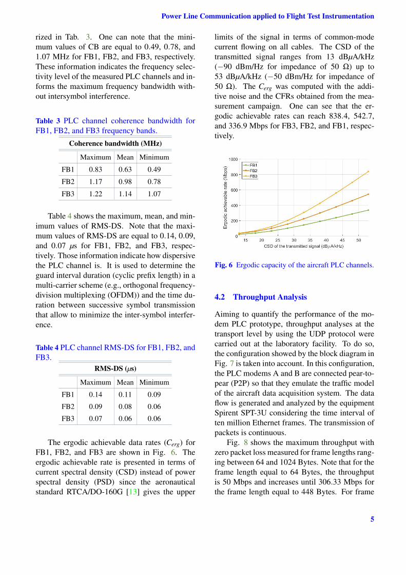
The ergodic achievable data rates (Cerg) forFB1, FB2, and FB3 are shown in Fig. 6. Theergodic achievable rate is presented in terms ofcurrent spectral density (CSD) instead of powerspectral density (PSD) since the aeronauticalstandard RTCA/DO-160G [13] gives the upper
limits of the signal in terms of common-modecurrent flowing on all cables. The CSD of thetransmitted signal ranges from 13 dBµA/kHz(−90 dBm/Hz for impedance of 50 Ω) up to53 dBµA/kHz (−50 dBm/Hz for impedance of50 Ω). The Cerg was computed with the addi-tive noise and the CFRs obtained from the mea-surement campaign. One can see that the er-godic achievable rates can reach 838.4, 542.7,and 336.9 Mbps for FB3, FB2, and FB1, respec-tively.
Fig. 6 Ergodic capacity of the aircraft PLC channels.
4.2 Throughput Analysis
Aiming to quantify the performance of the mo-dem PLC prototype, throughput analyses at thetransport level by using the UDP protocol werecarried out at the laboratory facility. To do so,the configuration showed by the block diagram inFig. 7 is taken into account. In this configuration,the PLC modems A and B are connected pear-to-pear (P2P) so that they emulate the traffic modelof the aircraft data acquisition system. The dataflow is generated and analyzed by the equipmentSpirent SPT-3U considering the time interval often million Ethernet frames. The transmission ofpackets is continuous.
Fig. 8 shows the maximum throughput withzero packet loss measured for frame lengths rang-ing between 64 and 1024 Bytes. Note that for theframe length equal to 64 Bytes, the throughputis 50 Mbps and increases until 306.33 Mbps forthe frame length equal to 448 Bytes. For frame
5
MOISES V. RIBEIRO
Fig. 7 Block diagram of CF #2.
lengths longer than 448 Bytes the throughput isalmost the same.
Fig. 8 Throughput Performance of the PLC mo-dem prototype.
5 Conclusion
In this paper, we have presented an statisticalcharacterization of the 28 Vdc electric powernetwork that deliveries energy to instrumenta-tion equipment of the business jet test prototype.Then ACA, CB, RMS-DS, and ergodic achiev-able rate parameters have been evaluated and dis-cussed. Also, we have presented the PLC modemprototype developed to operate in flight test air-craft. In order to verify its performance, through-put analysis at the transport level layer have beenprovided.
The numerical results has shown an ergodicachievable rate of 838.4, 542.7, and 336.9 Mbpsfor the frequency bands FB3, FB2, and FB1, re-spectively. Also, they has shown that the PLCmodem prototype in a P2P configuration canreach throughput equal to 306.33 Mbps, free ofpacket losses, by using the UDP protocol at thetransport layer level. Those results indicate thatthe PLC system can be interesting solution ofdata communication for flight test instrumenta-tion in aircrafts.
References
[1] Facina M S P, Latchman H A, Poor H V, andRibeiro M V. Cooperative in-home power linecommunication: Analyses based on a measure-ment campaign. IET Communications, Vol. 64,No. 2, pp 778-789, 2016.
[2] Costa L G S, Queiroz A C M, Adebisi B,Costa V L R, and Ribeiro M V. Coupling forpower line communications: A survey. Jour-nal of Communication and Information Sys-tems, forthcoming.
[3] Oliveira T R, Andrade F J A, Picorone A M,Latchman H A, Netto S L, and Ribeiro MV. Characterization of hybrid communicationchannel in indoor scenario. Journal of Commu-nication and Information Systems, Vol. 31, No.61, pp 224-235, 2016.
[4] Picorone A A M, Sampaio-Neto R, Ribeiro MV. Coherence time and sparsity of Brazilian out-door PLC channels: A preliminary analysis.Proc IEEE International Symposium on PowerLine Communications and Its Applications, pp1-5, 2014.
[5] Degauque P, Stievano I S, Pignari S A, DegardinV, Canavero F G, Grassi F, and Cañete F J.Power-line communication: Channel character-ization and modeling for transportation systems.IEEE Vehicular Technology Magazine, Vol. 10,No. 2, pp 28-37, 2015.
[6] Degardin V, Junqua I, Lienard M, DegauqueP, and Bertuol S. Theoretical approach to thefeasibility of power-line communication in air-crafts. IEEE Transactions on Vehicular Technol-ogy, Vol. 62, No. 3, pp 1362-1366, 2013.
[7] Bertuol S, Junqua I, Degardin V, Deguaque P,Dunand M, and Genoulaz J. Numerical assess-ment of propagation channel characteristics forfuture applications of power line communica-tion in aircraft. Proc. International Symposiumon Electromagnetic Compability - EMC Europe,pp 506-511, 2011.
[8] Degardin V, Laly P, Lienard M, and Degauque
6
Power Line Communication applied to Flight Test Instrumentation
P. Investigation on power line communication inaircrafts. IET Communications, Vol. 8, No. 10,pp 1868-1874, 2014.
[9] Dominiak S, Widmer H, and Bittner M. A bifilarapproach to power and data transmission overcommon wires in aircraft. Proc. IEEE/AIAADigital Avionics Systems Conference, pp 7B4,1-13, 2011.
[10] Camponogara Â, Oliveira R O, Machado R, Fi-namore W A and Ribeiro M V. Measurementand characterization of Aircraft PLC Channels.Master thesis, Federal University of Juiz deFora, Juiz de Fora, Minas Gerais, 2016.
[11] Camponogara Â, Oliveira R O, Machado R, Fi-namore W A, Campos F V P de, and RibeiroM V. Aircraft PLC channels characterization:initial discussion. Proc Brazilian Symposium onTelecommunications, pp 1-4, 2016.
[12] Oliveira T R, Marques C A G, Finamore W A,Netto S L, Ribeiro M V. A methodology for es-timating frequency responses of electric powergrids. Journal of Control, Automation and Elec-trical Systems. Vol. 25, No. 6, pp 720-731, 2014.
[13] RTCA/DO-160G - Environment conditions andtest procedures for airborne equipment, RadioTechnical Commission for Aeronautics (RTCA)Std., Dec. 2010.
Copyright Statement
The authors confirm that they, and/or their companyor organization, hold copyright on all of the origi-nal material included in this paper. The authors alsoconfirm that they have obtained permission, from thecopyright holder of any third party material includedin this paper, to publish it as part of their paper. Theauthors confirm that they give permission, or have ob-tained permission from the copyright holder of thispaper, for the publication and distribution of this pa-per as part of the ICAS proceedings or as individualoff-prints from the proceedings.


![Flight Data Tools Applied to Engine Health Monitoring · Flight Data Tools Applied to Engine Health Monitoring ... GE90-115B[6] ... RPM Rotations Per Minute.](https://static.documents.pub/doc/80x56/5b1e4d3c7f8b9ae6418b653c/flight-data-tools-applied-to-engine-health-monitoring-flight-data-tools-applied.jpg)


