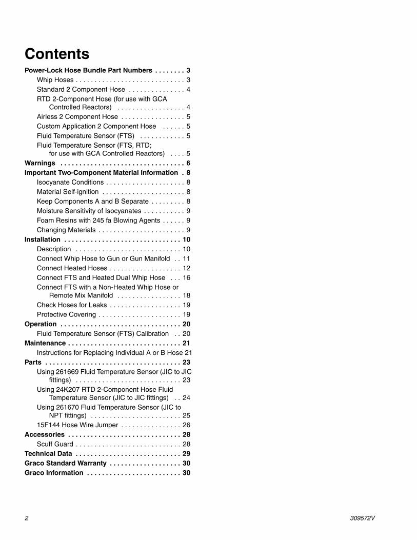
Instructions - Parts Power-Lock ™ Heated Hose For use with plural component proportioners. For professional use only. Not approved for use in European explosive atmospheres. See page 3 for Maximum Fluid Working Pressure 130 psi (0.9 MPa, 9 bar) Maximum Air Working Pressure 180°F (82°C) Maximum Hose Operating Temperature Important Safety instructions. Read all warnings and instructions in this manual. Save these instructions. See page 3 for a list of part numbers. TI12157a 309572V EN
Transcript
Instructions - Parts
Power-Lock™
Heated Hose
For use with plural component proportioners. For professional use only.Not approved for use in European explosive atmospheres.
See page 3 for Maximum Fluid Working Pressure
130 psi (0.9 MPa, 9 bar) Maximum Air Working Pressure
180°F (82°C) Maximum Hose Operating Temperature
Important Safety instructions. Read all warnings and instructions in this manual.Save these instructions. See page 3 for a list of part numbers.
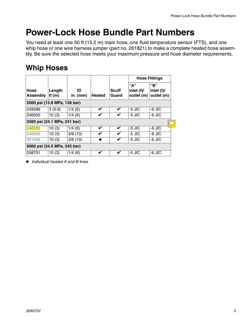
Power-Lock Hose Bundle Part NumbersYou need at least one 50 ft (15.2 m) main hose, one fluid temperature sensor (FTS), and one whip hose or one wire harness jumper (part no. 261821) to make a complete heated hose assem-bly. Be sure the selected hose meets your maximum pressure and hose diameter requirements.
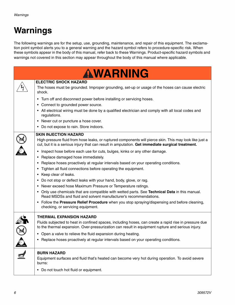
WarningsThe following warnings are for the setup, use, grounding, maintenance, and repair of this equipment. The exclama-tion point symbol alerts you to a general warning and the hazard symbol refers to procedure-specific risk. When these symbols appear in the body of this manual, refer back to these Warnings. Product-specific hazard symbols and warnings not covered in this section may appear throughout the body of this manual where applicable.
WARNINGWARNINGWARNINGWARNINGELECTRIC SHOCK HAZARD The hoses must be grounded. Improper grounding, set-up or usage of the hoses can cause electric shock.
• Turn off and disconnect power before installing or servicing hoses.
• Connect to grounded power source.
• All electrical wiring must be done by a qualified electrician and comply with all local codes and regulations.
• Never cut or puncture a hose cover.
• Do not expose to rain. Store indoors.
SKIN INJECTION HAZARD High-pressure fluid from hose leaks, or ruptured components will pierce skin. This may look like just a cut, but it is a serious injury that can result in amputation. Get immediate surgical treatment.
• Inspect hose before each use for cuts, bulges, kinks or any other damage.
• Replace damaged hose immediately.
• Replace hoses proactively at regular intervals based on your operating conditions.
• Tighten all fluid connections before operating the equipment.
• Keep clear of leaks.
• Do not stop or deflect leaks with your hand, body, glove, or rag.
• Never exceed hose Maximum Pressure or Temperature ratings.
• Only use chemicals that are compatible with wetted parts. See Technical Data in this manual. Read MSDSs and fluid and solvent manufacturer’s recommendations.
• Follow the Pressure Relief Procedure when you stop spraying/dispensing and before cleaning, checking, or servicing equipment.
THERMAL EXPANSION HAZARDFluids subjected to heat in confined spaces, including hoses, can create a rapid rise in pressure due to the thermal expansion. Over-pressurization can result in equipment rupture and serious injury.
• Open a valve to relieve the fluid expansion during heating.
• Replace hoses proactively at regular intervals based on your operating conditions.
BURN HAZARD Equipment surfaces and fluid that’s heated can become very hot during operation. To avoid severe burns:
• Do not touch hot fluid or equipment.
Warnings
309572V 7
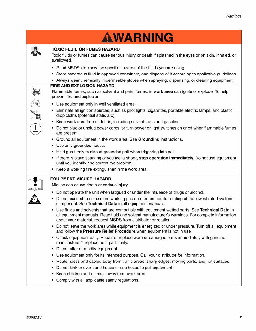
TOXIC FLUID OR FUMES HAZARD Toxic fluids or fumes can cause serious injury or death if splashed in the eyes or on skin, inhaled, or swallowed.
• Read MSDSs to know the specific hazards of the fluids you are using.
• Store hazardous fluid in approved containers, and dispose of it according to applicable guidelines.
• Always wear chemically impermeable gloves when spraying, dispensing, or cleaning equipment.FIRE AND EXPLOSION HAZARD Flammable fumes, such as solvent and paint fumes, in work area can ignite or explode. To help prevent fire and explosion:
• Use equipment only in well ventilated area.
• Eliminate all ignition sources; such as pilot lights, cigarettes, portable electric lamps, and plastic drop cloths (potential static arc).
• Keep work area free of debris, including solvent, rags and gasoline.
• Do not plug or unplug power cords, or turn power or light switches on or off when flammable fumes are present.
• Ground all equipment in the work area. See Grounding instructions.
• Use only grounded hoses.
• Hold gun firmly to side of grounded pail when triggering into pail.
• If there is static sparking or you feel a shock, stop operation immediately. Do not use equipment until you identify and correct the problem.
• Keep a working fire extinguisher in the work area.
EQUIPMENT MISUSE HAZARD Misuse can cause death or serious injury.
• Do not operate the unit when fatigued or under the influence of drugs or alcohol.
• Do not exceed the maximum working pressure or temperature rating of the lowest rated system component. See Technical Data in all equipment manuals.
• Use fluids and solvents that are compatible with equipment wetted parts. See Technical Data in all equipment manuals. Read fluid and solvent manufacturer’s warnings. For complete information about your material, request MSDS from distributor or retailer.
• Do not leave the work area while equipment is energized or under pressure. Turn off all equipment and follow the Pressure Relief Procedure when equipment is not in use.
• Check equipment daily. Repair or replace worn or damaged parts immediately with genuine manufacturer’s replacement parts only.
• Do not alter or modify equipment.
• Use equipment only for its intended purpose. Call your distributor for information.
• Route hoses and cables away from traffic areas, sharp edges, moving parts, and hot surfaces.
• Do not kink or over bend hoses or use hoses to pull equipment.
• Keep children and animals away from work area.
• Comply with all applicable safety regulations.
WARNINGWARNINGWARNINGWARNING
Important Two-Component Material Information
8 309572V
Important Two-Component Material Information
Isocyanate Conditions
Material Self-ignition
Keep Components A and B Separate
PERSONAL PROTECTIVE EQUIPMENTYou must wear appropriate protective equipment when operating, servicing, or when in the operating area of the equipment to help protect you from serious injury, including eye injury, hearing loss, inhala-tion of toxic fumes, and burns. This equipment includes but is not limited to:• Protective eyewear, and hearing protection.• Respirators, protective clothing, and gloves as recommended by the fluid and solvent manufacturer.
WARNINGWARNINGWARNINGWARNING
Spraying or dispensing materials containing isocyanates creates potentially harmful mists, vapors, and atomized particulates.
Read material manufacturer’s warnings and material MSDS to know specific hazards and precautions related to isocyanates.
Prevent inhalation of isocyanate mists, vapors, and atomized particulates by providing sufficient ventilation in the work area. If sufficient ventilation is not available, a supplied-air respirator is required for everyone in the work area.
To prevent contact with isocyanates, appropriate personal protective equipment, including chemically impermeable gloves, boots, aprons, and goggles, is also required for everyone in the work area.
Some materials may become self-igniting if applied too thickly. Read material manufacturer’s warnings and material MSDS.
Cross-contamination can result in cured material in fluid lines which could cause serious injury or damage equipment. To prevent cross-contamination of the equipment’s wetted parts, never interchange component A (isocyanate) and component B (resin) parts.
Important Two-Component Material Information
309572V 9
Moisture Sensitivity of IsocyanatesIsocyanates (ISO) are catalysts used in two component foam and polyurea coatings. ISO will react with moisture (such as humidity) to form small, hard, abrasive crystals, which become suspended in the fluid. Eventually a film will form on the surface and the ISO will begin to gel, increasing in viscosity. If used, this partially cured ISO will reduce performance and the life of all wetted parts.
NOTE: The amount of film formation and rate of crystal-lization varies depending on the blend of ISO, the humidity, and the temperature.
To prevent exposing ISO to moisture:
• Always use a sealed container with a desiccant dryer in the vent, or a nitrogen atmosphere. Never store ISO in an open container.
• Keep the ISO lube pump reservoir (if installed) filled
with Graco® Throat Seal Liquid (TSL™), Part 206995. The lubricant creates a barrier between the ISO and the atmosphere.
• Use moisture-proof hoses specifically designed for ISO, such as those supplied with your system.
• Never use reclaimed solvents, which may contain moisture. Always keep solvent containers closed when not in use.
• Never use solvent on one side if it has been contam-inated from the other side.
• Always lubricate threaded parts with ISO pump oil or grease when reassembling.
Foam Resins with 245 fa Blowing AgentsSome foam blowing agents will froth at temperatures above 90°F (33°C) when not under pressure, especially if agitated. To reduce frothing, minimize preheating in a circulation system.
Changing Materials• When changing materials, flush the equipment mul-
tiple times to ensure it is thoroughly clean.
• Always clean the fluid inlet strainers after flushing.
• Check with your material manufacturer for chemical compatibility.
• Most materials use ISO on the A side, but some use ISO on the B side.
• Epoxies often have amines on the B (hardener) side. Polyureas often have amines on the B (resin) side.
Installation
10 309572V
Installation
Description
The heated hose maintains proper fluid tem-perature while spraying.
Fluid hoses are marked with red tape for ISO/hardener/minor volume side, blue tape for RES/resin/major volume side. Fittings have dif-ferent sized threads to prevent incorrect con-nection, which can cause fluid crossover and permanently damage the hose.
Hoses are 50 ft (15.2 m) or 25 ft (7.6 m) long. The whip hose is 10 ft (3 m) long or less.
This hose must be used with an FTS and cable to provide grounding.
To heat the major volume hose only in a wide ratio system, see 15F144 Hose Wire Jumper, page 26.
Installation
309572V 11
Connect Whip Hose to Gun or Gun Manifold
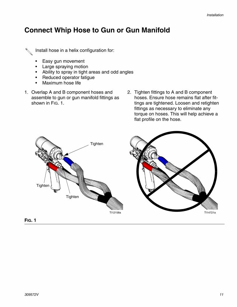
1. Overlap A and B component hoses and assemble to gun or gun manifold fittings as shown in FIG. 1.
2. Tighten fittings to A and B component hoses. Ensure hose remains flat after fit-tings are tightened. Loosen and retighten fittings as necessary to eliminate any torque on hoses. This will help achieve a flat profile on the hose.
Install hose in a helix configuration for:
• Easy gun movement• Large spraying motion• Ability to spray in tight areas and odd angles• Reduced operator fatigue• Maximum hose life
FIG. 1
Tighten
Tighten
Tighten
TI12158a TI14721a
Installation
12 309572V
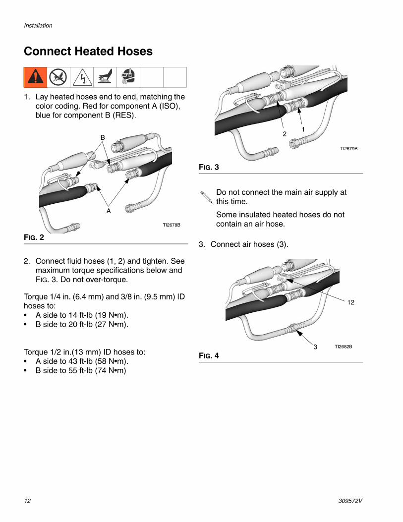
Connect Heated Hoses
1. Lay heated hoses end to end, matching the color coding. Red for component A (ISO), blue for component B (RES).
2. Connect fluid hoses (1, 2) and tighten. See maximum torque specifications below and FIG. 3. Do not over-torque.
Torque 1/4 in. (6.4 mm) and 3/8 in. (9.5 mm) ID hoses to:• A side to 14 ft-lb (19 N•m). • B side to 20 ft-lb (27 N•m).
Torque 1/2 in.(13 mm) ID hoses to: • A side to 43 ft-lb (58 N•m). • B side to 55 ft-lb (74 N•m)
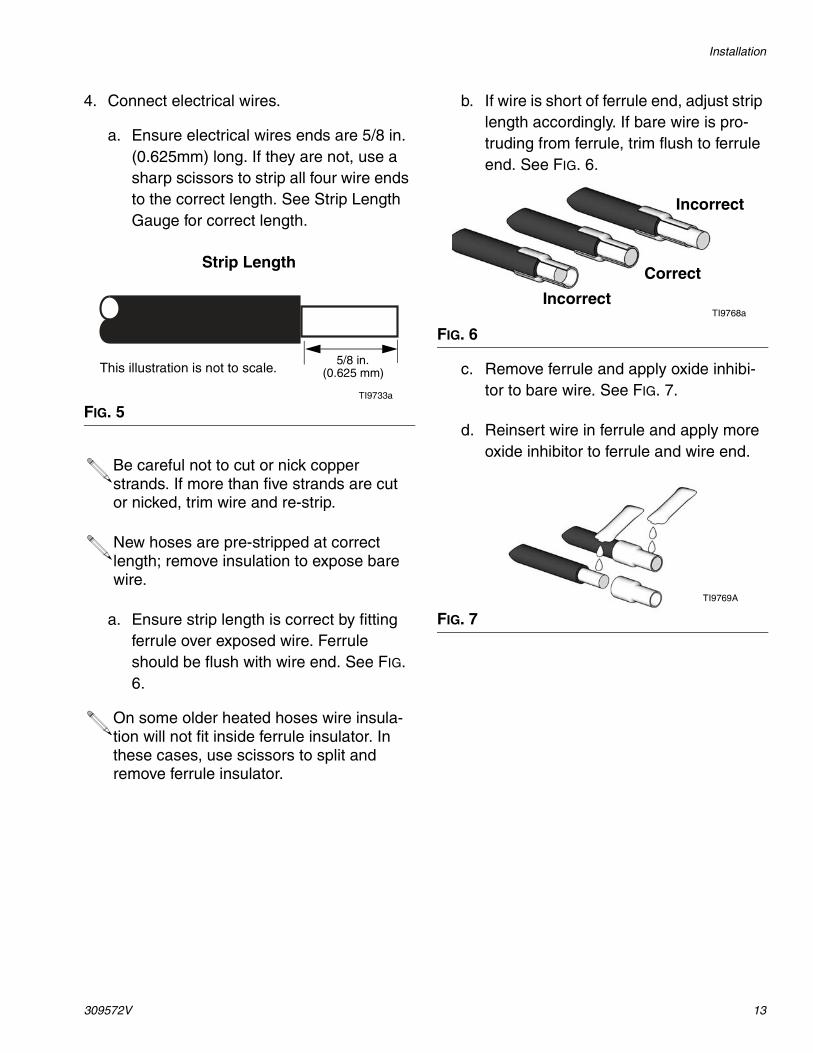
3. Connect air hoses (3).FIG. 2
A
B
TI2678B
FIG. 3
Do not connect the main air supply at this time.
Some insulated heated hoses do not contain an air hose.
FIG. 4
TI2679B
21
3 TI2682B
12
Installation
309572V 13
4. Connect electrical wires.
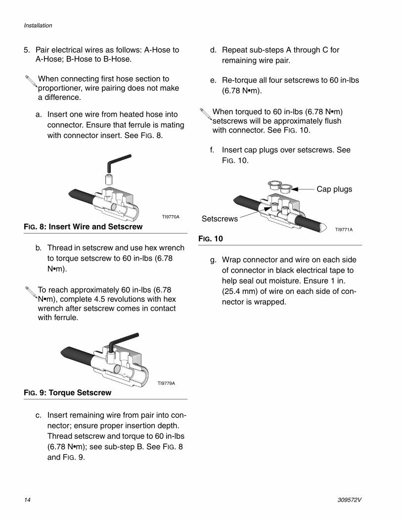
a. Ensure electrical wires ends are 5/8 in. (0.625mm) long. If they are not, use a sharp scissors to strip all four wire ends to the correct length. See Strip Length Gauge for correct length.
a. Ensure strip length is correct by fitting ferrule over exposed wire. Ferrule should be flush with wire end. See FIG. 6.
b. If wire is short of ferrule end, adjust strip length accordingly. If bare wire is pro-truding from ferrule, trim flush to ferrule end. See FIG. 6.
c. Remove ferrule and apply oxide inhibi-tor to bare wire. See FIG. 7.
d. Reinsert wire in ferrule and apply more oxide inhibitor to ferrule and wire end.
FIG. 5
Be careful not to cut or nick copper strands. If more than five strands are cut or nicked, trim wire and re-strip.
New hoses are pre-stripped at correct length; remove insulation to expose bare wire.
On some older heated hoses wire insula-tion will not fit inside ferrule insulator. In these cases, use scissors to split and remove ferrule insulator.
Strip Length
5/8 in.
TI9733a
(0.625 mm)This illustration is not to scale.
FIG. 6
FIG. 7
Incorrect
Correct
IncorrectTI9768a
TI9769A
Installation
14 309572V
5. Pair electrical wires as follows: A-Hose to A-Hose; B-Hose to B-Hose.
a. Insert one wire from heated hose into connector. Ensure that ferrule is mating with connector insert. See FIG. 8.
b. Thread in setscrew and use hex wrench to torque setscrew to 60 in-lbs (6.78 N•m).
c. Insert remaining wire from pair into con-nector; ensure proper insertion depth. Thread setscrew and torque to 60 in-lbs (6.78 N•m); see sub-step B. See FIG. 8 and FIG. 9.
d. Repeat sub-steps A through C for remaining wire pair.
e. Re-torque all four setscrews to 60 in-lbs (6.78 N•m).
f. Insert cap plugs over setscrews. See FIG. 10.
g. Wrap connector and wire on each side of connector in black electrical tape to help seal out moisture. Ensure 1 in. (25.4 mm) of wire on each side of con-nector is wrapped.
When connecting first hose section to proportioner, wire pairing does not make a difference.
FIG. 8: Insert Wire and Setscrew
To reach approximately 60 in-lbs (6.78 N•m), complete 4.5 revolutions with hex wrench after setscrew comes in contact with ferrule.
FIG. 9: Torque Setscrew
TI9770A
TI9779A
When torqued to 60 in-lbs (6.78 N•m) setscrews will be approximately flush with connector. See FIG. 10.
FIG. 10
Cap plugs
SetscrewsTI9771A
Installation
309572V 15
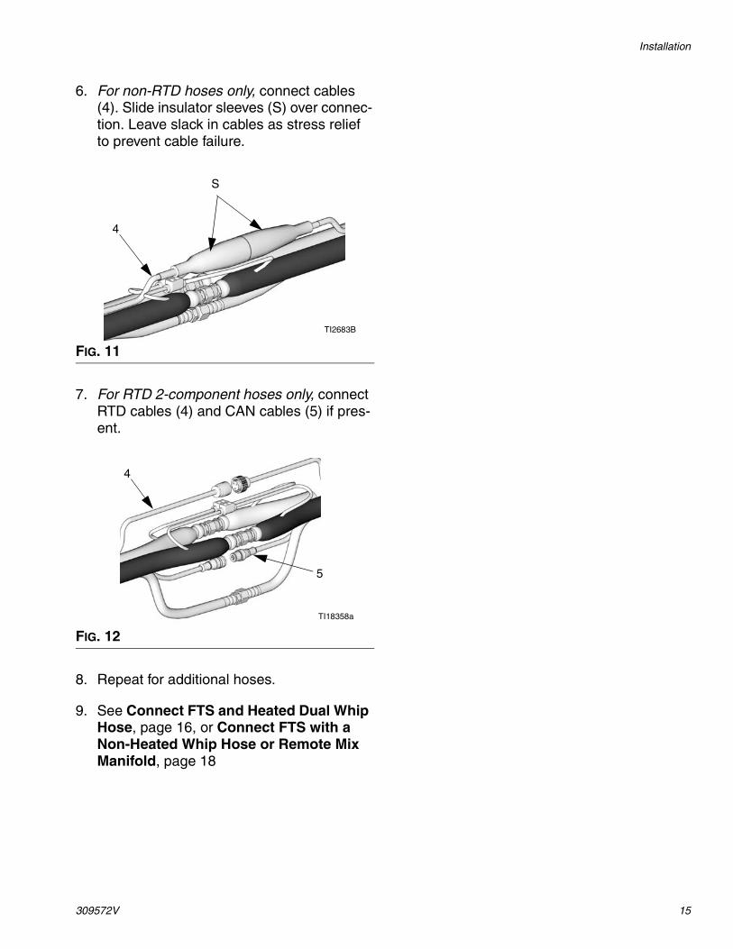
6. For non-RTD hoses only, connect cables (4). Slide insulator sleeves (S) over connec-tion. Leave slack in cables as stress relief to prevent cable failure.
7. For RTD 2-component hoses only, connect RTD cables (4) and CAN cables (5) if pres-ent.
8. Repeat for additional hoses.
9. See Connect FTS and Heated Dual Whip Hose, page 16, or Connect FTS with a Non-Heated Whip Hose or Remote Mix Manifold, page 18
FIG. 11
FIG. 12
TI2683B
S
4
TI18358a
5
4
Installation
16 309572V
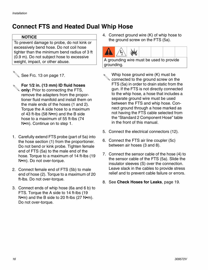
Connect FTS and Heated Dual Whip Hose
1. Carefully extend FTS probe (part of 5a) into the hose section (1) from the proportioner. Do not bend or kink probe. Tighten female end of FTS (5a) to the male end of the hose. Torque to a maximum of 14 ft-lbs (19 N•m). Do not over-torque.
2. Connect female end of FTS (5b) to male end of hose (2). Torque to a maximum of 20 ft-lbs. Do not over-torque.
3. Connect ends of whip hose (6a and 6 b) to FTS. Torque the A side to 14 ft-lbs (19 N•m) and the B side to 20 ft-lbs (27 N•m). Do not over-torque.
4. Connect ground wire (K) of whip hose to the ground screw on the FTS (5a).
5. Connect the electrical connectors (12).
6. Connect the FTS air line coupler (5c) between air hoses (3 and 8).
7. Connect the sensor cable of the hose (4) to the sensor cable of the FTS (5a). Slide the insulator sleeves (S) over the connection. Leave slack in the cables to provide stress relief and to prevent cable failure or errors.
8. See Check Hoses for Leaks, page 19.
NOTICETo prevent damage to probe, do not kink or excessively bend hose. Do not coil hose tighter than the minimum bend radius of 3 ft (0.9 m). Do not subject hose to excessive weight, impact, or other abuse.
See FIG. 13 on page 17.
For 1/2 in. (13 mm) ID fluid hoses only: Prior to connecting the FTS, remove the adapters from the propor-tioner fluid manifold and install them on the male ends of the hoses (1 and 2). Torque the A side hose to a maximum of 43 ft-lbs (58 N•m) and the B side hose to a maximum of 55 ft-lbs (74 N•m). Continue on to step 1.
A grounding wire must be used to provide grounding.
Whip hose ground wire (K) must be connected to the ground screw on the FTS (5a) in order to drain static from the gun. If the FTS is not directly connected to the whip hose, a hose that includes a separate ground wire must be used between the FTS and whip hose. Con-nect ground through a hose marked as not having the FTS cable selected from the “Standard 2 Component Hose” table in the front of this manual.
Installation
309572V 17
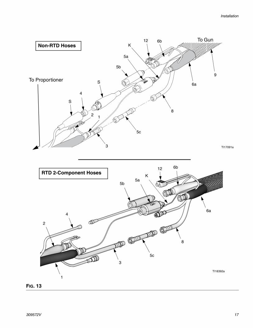
FIG. 13
2 1
6a
6bK
5c
12
5b
8
TI17091a
4
9
S
S
To Gun
To Proportioner
3
5a
TI18392a
Non-RTD Hoses
RTD 2-Component Hoses5a
1
2
5b
6a
6b
K
12
3
8
4
5c
Installation
18 309572V
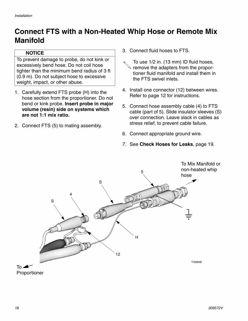
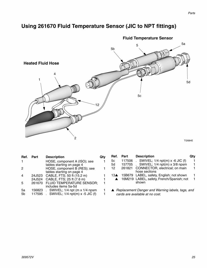
Connect FTS with a Non-Heated Whip Hose or Remote Mix Manifold
1. Carefully extend FTS probe (H) into the hose section from the proportioner. Do not bend or kink probe. Insert probe in major volume (resin) side on systems which are not 1:1 mix ratio.
2. Connect FTS (5) to mating assembly.
3. Connect fluid hoses to FTS.
4. Install one connector (12) between wires. Refer to page 12 for instructions.
5. Connect hose assembly cable (4) to FTS cable (part of 5). Slide insulator sleeves (S) over connection. Leave slack in cables as stress relief, to prevent cable failure.
6. Connect appropriate ground wire.
7. See Check Hoses for Leaks, page 19.
NOTICETo prevent damage to probe, do not kink or excessively bend hose. Do not coil hose tighter than the minimum bend radius of 3 ft (0.9 m). Do not subject hose to excessive weight, impact, or other abuse.
To use 1/2 in. (13 mm) ID fluid hoses, remove the adapters from the propor-tioner fluid manifold and install them in the FTS swivel inlets.
5
S
H
TI2684E
S
4
To Mix Manifold or non-heated whip hose
To Proportioner
12
Installation
309572V 19
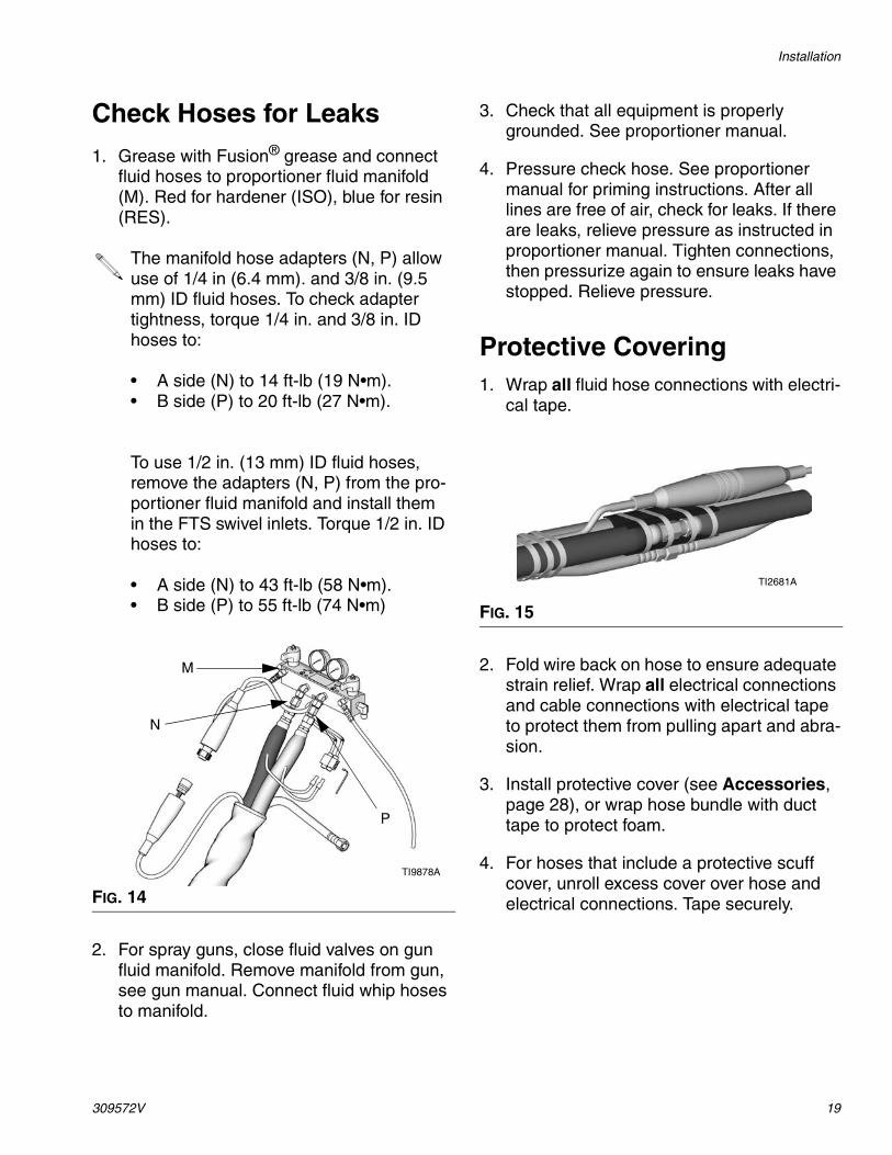
Check Hoses for Leaks
1. Grease with Fusion® grease and connect fluid hoses to proportioner fluid manifold (M). Red for hardener (ISO), blue for resin (RES).
2. For spray guns, close fluid valves on gun fluid manifold. Remove manifold from gun, see gun manual. Connect fluid whip hoses to manifold.
3. Check that all equipment is properly grounded. See proportioner manual.
4. Pressure check hose. See proportioner manual for priming instructions. After all lines are free of air, check for leaks. If there are leaks, relieve pressure as instructed in proportioner manual. Tighten connections, then pressurize again to ensure leaks have stopped. Relieve pressure.
Protective Covering1. Wrap all fluid hose connections with electri-
cal tape.
2. Fold wire back on hose to ensure adequate strain relief. Wrap all electrical connections and cable connections with electrical tape to protect them from pulling apart and abra-sion.
3. Install protective cover (see Accessories, page 28), or wrap hose bundle with duct tape to protect foam.
4. For hoses that include a protective scuff cover, unroll excess cover over hose and electrical connections. Tape securely.
The manifold hose adapters (N, P) allow use of 1/4 in (6.4 mm). and 3/8 in. (9.5 mm) ID fluid hoses. To check adapter tightness, torque 1/4 in. and 3/8 in. ID hoses to:
• A side (N) to 14 ft-lb (19 N•m).• B side (P) to 20 ft-lb (27 N•m).
To use 1/2 in. (13 mm) ID fluid hoses, remove the adapters (N, P) from the pro-portioner fluid manifold and install them in the FTS swivel inlets. Torque 1/2 in. ID hoses to:
• A side (N) to 43 ft-lb (58 N•m).• B side (P) to 55 ft-lb (74 N•m)
FIG. 14
TI9878A
M
N
P
FIG. 15
TI2681A
Operation
20 309572V
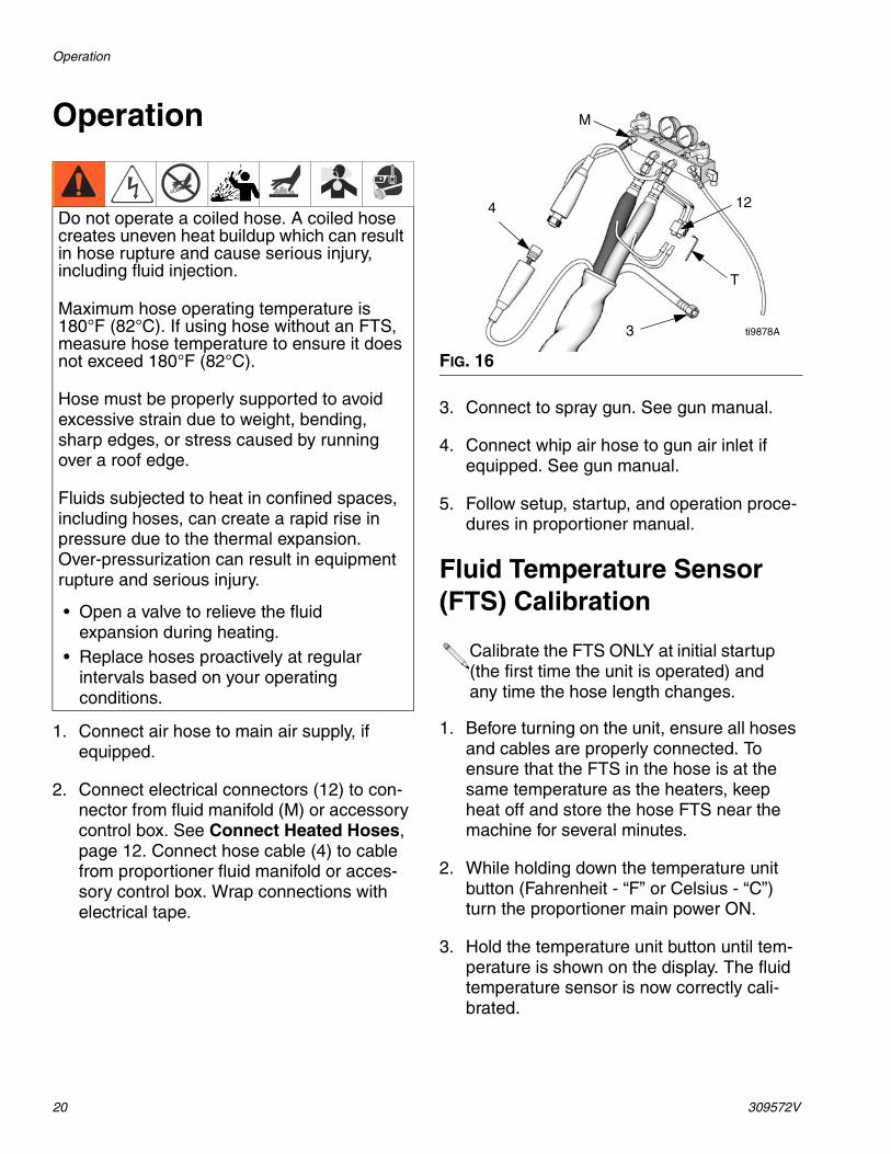
Operation
1. Connect air hose to main air supply, if equipped.
2. Connect electrical connectors (12) to con-nector from fluid manifold (M) or accessory control box. See Connect Heated Hoses, page 12. Connect hose cable (4) to cable from proportioner fluid manifold or acces-sory control box. Wrap connections with electrical tape.
3. Connect to spray gun. See gun manual.
4. Connect whip air hose to gun air inlet if equipped. See gun manual.
5. Follow setup, startup, and operation proce-dures in proportioner manual.
Fluid Temperature Sensor (FTS) Calibration
1. Before turning on the unit, ensure all hoses and cables are properly connected. To ensure that the FTS in the hose is at the same temperature as the heaters, keep heat off and store the hose FTS near the machine for several minutes.
2. While holding down the temperature unit button (Fahrenheit - “F” or Celsius - “C”) turn the proportioner main power ON.
3. Hold the temperature unit button until tem-perature is shown on the display. The fluid temperature sensor is now correctly cali-brated.
Do not operate a coiled hose. A coiled hose creates uneven heat buildup which can result in hose rupture and cause serious injury, including fluid injection.
Maximum hose operating temperature is 180°F (82°C). If using hose without an FTS, measure hose temperature to ensure it does not exceed 180°F (82°C).
Hose must be properly supported to avoid excessive strain due to weight, bending, sharp edges, or stress caused by running over a roof edge.
Fluids subjected to heat in confined spaces, including hoses, can create a rapid rise in pressure due to the thermal expansion. Over-pressurization can result in equipment rupture and serious injury.
• Open a valve to relieve the fluid expansion during heating.
• Replace hoses proactively at regular intervals based on your operating conditions.
FIG. 16
Calibrate the FTS ONLY at initial startup (the first time the unit is operated) and any time the hose length changes.
M
4
3
12
T
ti9878A
Maintenance
309572V 21
Maintenance
1. Before disconnecting or repairing hoses, relieve all fluid pressure and shut off electri-cal power to proportioner. See proportioner operation manual.
2. Be sure fluid is cool before disconnecting hoses.
Instructions for Replacing Individual A or B HoseBefore disconnecting hoses, relieve all fluid pressure and shut off electrical power to pro-portioner. See proportioner operation manual.
Disconnect electrical wire from connectors (12). Disconnect fluid hose and remove from bundle.
Install new hose in bundle, wrapping around other fluid hose and air hose. Connect fluid hoses, see page 12.
Connect electrical wire from new hose into connectors (12). Ensure that component A (ISO) wire is on + side of connector, compo-nent B (RES) wire is on - side. See page 12.
Wrap all connections with electrical tape, see page 19.
Maintenance
22 309572V
Parts
309572V 23
Parts
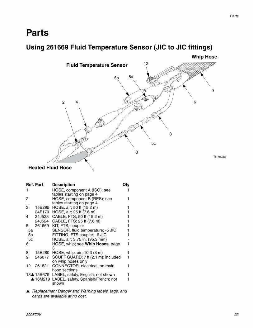
Using 261669 Fluid Temperature Sensor (JIC to JIC fittings)
▲ Replacement Danger and Warning labels, tags, and cards are available at no cost.
2
5b
4
Heated Fluid Hose
Fluid Temperature Sensor
Whip Hose
1
TI17092a
12
3
5a
5c
8
6
9
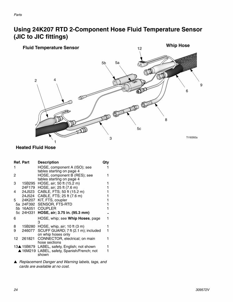
Ref. Part Description Qty1 HOSE, component A (ISO); see
tables starting on page 41
2 HOSE, component B (RES); see tables starting on page 4
1
3 15B295 HOSE, air; 50 ft (15.2 m) 124F179 HOSE, air; 25 ft (7.6 m) 1
4 24J523 CABLE, FTS; 50 ft (15.2 m) 124J524 CABLE, FTS; 25 ft (7.6 m) 1
102 24J523 CABLE, FTS 1104 261670 FLUID TEMPERATURE
SENSOR; see page 231
105 pur-chase locally
HOSE, hardener, unheated; 50 ft (15.2 m) minimum; customer supplied
1
106 pur-chase locally
CONNECTORS, fluid; as required to complete assem-bly; not shown
asreq’d
This hose must be used with an FTS and cable to provide grounding.
Parts
309572V 27
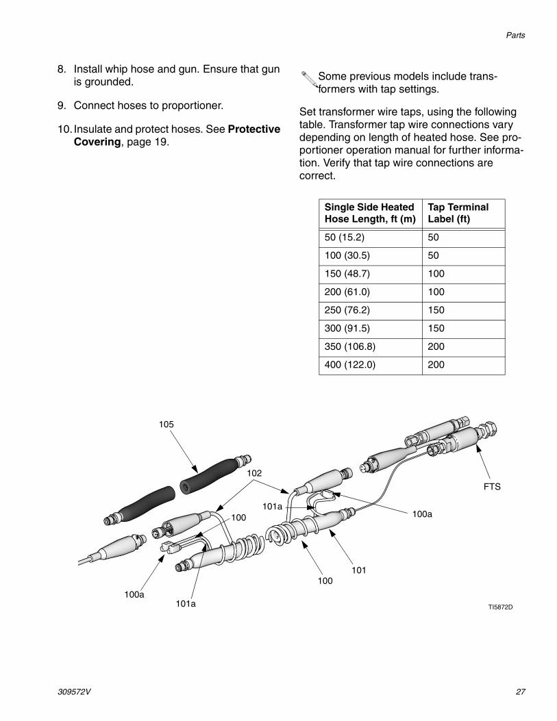
8. Install whip hose and gun. Ensure that gun is grounded.
9. Connect hoses to proportioner.
10. Insulate and protect hoses. See Protective Covering, page 19.
Set transformer wire taps, using the following table. Transformer tap wire connections vary depending on length of heated hose. See pro-portioner operation manual for further informa-tion. Verify that tap wire connections are correct.
Some previous models include trans-formers with tap settings.
Single Side Heated Hose Length, ft (m)
Tap Terminal Label (ft)
50 (15.2) 50
100 (30.5) 50
150 (48.7) 100
200 (61.0) 100
250 (76.2) 150
300 (91.5) 150
350 (106.8) 200
400 (122.0) 200
105
TI5872D
100a
102
100
100
100a101a
101a
101
FTS
Accessories
28 309572V
Accessories
Scuff GuardUse to keep hose clean and protect it from damage.
Part Description246077 7 ft (2.1 m) braided polyester
mesh. For whip hose. Fold back over itself for easy installation.
246078 50 ft (15.2 m) braided polyester mesh. Fold back over itself for easy instal-lation.
246805 25 ft (7.6 m) braided polyester mesh. Fold back over itself for easy instal-lation.
246456 50 ft (15.2 m) polyethylene bag. Inflate with air for easy installation.
Technical Data
309572V 29
Technical Data
Category DataMaximum Fluid Working Pressure
See page 3
Maximum Air Working Pressure
130 psi (0.9 MPa, 9 bar)
Maximum Operating Temperature
180°F (82°C)
Wetted Parts Nylon, Zinc-Plated Carbon Steel, 303 Stainless Steel
Total Heating Load (2 hoses)
1/4” diameter: 11 watts/foot(36 watts/meter)
3/8’ diameter: 13 watts/foot(43 watts/meter)
1/2” diameter: 15 watts/foot(49 watts/meter)
All written and visual data contained in this document reflects the latest product information available at the time of publication. Graco reserves the right to make changes at any time without notice.
Original instructions. This manual contains English. MM 309572
Graco Headquarters: MinneapolisInternational Offices: Belgium, China, Japan, Korea
GRACO INC. AND SUBSIDIARIES • P.O. BOX 1441 • MINNEAPOLIS MN 55440-1441 • USACopyright 2002, Graco Inc. All Graco manufacturing locations are registered to ISO 9001.
www.graco.comRevised 12/2011
Graco Standard WarrantyGraco warrants all equipment referenced in this document which is manufactured by Graco and bearing its name to be free from defects in material and workmanship on the date of sale to the original purchaser for use. With the exception of any special, extended, or limited warranty published by Graco, Graco will, for a period of twelve months from the date of sale, repair or replace any part of the equipment determined by Graco to be defective. This warranty applies only when the equipment is installed, operated and maintained in accordance with Graco’s written recommendations.
This warranty does not cover, and Graco shall not be liable for general wear and tear, or any malfunction, damage or wear caused by faulty installation, misapplication, abrasion, corrosion, inadequate or improper maintenance, negligence, accident, tampering, or substitution of non-Graco component parts. Nor shall Graco be liable for malfunction, damage or wear caused by the incompatibility of Graco equipment with structures, accessories, equipment or materials not supplied by Graco, or the improper design, manufacture, installation, operation or maintenance of structures, accessories, equipment or materials not supplied by Graco.
This warranty is conditioned upon the prepaid return of the equipment claimed to be defective to an authorized Graco distributor for verification of the claimed defect. If the claimed defect is verified, Graco will repair or replace free of charge any defective parts. The equipment will be returned to the original purchaser transportation prepaid. If inspection of the equipment does not disclose any defect in material or workmanship, repairs will be made at a reasonable charge, which charges may include the costs of parts, labor, and transportation.
THIS WARRANTY IS EXCLUSIVE, AND IS IN LIEU OF ANY OTHER WARRANTIES, EXPRESS OR IMPLIED, INCLUDING BUT NOT LIMITED TO WARRANTY OF MERCHANTABILITY OR WARRANTY OF FITNESS FOR A PARTICULAR PURPOSE.
Graco’s sole obligation and buyer’s sole remedy for any breach of warranty shall be as set forth above. The buyer agrees that no other remedy (including, but not limited to, incidental or consequential damages for lost profits, lost sales, injury to person or property, or any other incidental or consequential loss) shall be available. Any action for breach of warranty must be brought within two (2) years of the date of sale.
GRACO MAKES NO WARRANTY, AND DISCLAIMS ALL IMPLIED WARRANTIES OF MERCHANTABILITY AND FITNESS FOR A PARTICULAR PURPOSE, IN CONNECTION WITH ACCESSORIES, EQUIPMENT, MATERIALS OR COMPONENTS SOLD BUT NOT MANUFACTURED BY GRACO. These items sold, but not manufactured by Graco (such as electric motors, switches, hose, etc.), are subject to the warranty, if any, of their manufacturer. Graco will provide purchaser with reasonable assistance in making any claim for breach of these warranties.
In no event will Graco be liable for indirect, incidental, special or consequential damages resulting from Graco supplying equipment hereunder, or the furnishing, performance, or use of any products or other goods sold hereto, whether due to a breach of contract, breach of warranty, the negligence of Graco, or otherwise.
FOR GRACO CANADA CUSTOMERSThe Parties acknowledge that they have required that the present document, as well as all documents, notices and legal proceedings entered into, given or instituted pursuant hereto or relating directly or indirectly hereto, be drawn up in English. Les parties reconnaissent avoir convenu que la rédaction du présente document sera en Anglais, ainsi que tous documents, avis et procédures judiciaires exécutés, donnés ou intentés, à la suite de ou en rapport, directement ou indirectement, avec les procédures concernées.
Graco InformationFor the latest information about Graco products, visit www.graco.com.
TO PLACE AN ORDER, contact your Graco distributor, or call this number to identify the distribu-tor closest to you: 1-800-328-0211 Toll Free