*TM 5-6115-629-14&P TECHNICAL MANUAL OPERATOR, UNIT, INTERMEDIATE DIRECT SUPPORT AND INTERMEDIATE GENERAL SUPPORT MAINTENANCE MANUAL (INCLUDING REPAIR PARTS AND SPECIAL TOOLS LISTS) POWER PLANT AN/MJQ-12A (NSN 6115-00-257-1602) (2) MEP-006A 60 KW 60 HZ GENERATOR SETS (2) M200A1 2-WHEEL, 4-TIRE, MODIFIED TRAILERS Approved for public release. Distribution is unlimited. *This manual supersedes Chapter 11 of TM 5-6115-594-14&P dated 25 September 1984. HEADQUARTERS, DEPARTMENT OF THE ARMY 17 JUNE 1988
Transcript
* T M 5 - 6 1 1 5 - 6 2 9 - 1 4 & P
TECHNICAL MANUAL
OPERATOR, UN IT , INTERMEDIATE D IRECT SUPPORTAND INTERMEDIATE GENERAL SUPPORT MAINTENANCE
MANUAL ( INCLUDING REPAIR PARTS ANDSPECIAL TOOLS L ISTS)
P O W E R P L A N TA N / M J Q - 1 2 A ( N S N 6 1 1 5 - 0 0 - 2 5 7 - 1 6 0 2 )
(2) MEP-006A 60 KW 60 HZG E N E R A T O R S E T S
(2) M200A1 2-WHEEL, 4 -T IRE,
M O D I F I E D T R A I L E R S
Approved for public release. Distribution is unlimited.
*This manual supersedes Chapter 11 of TM 5-6115-594-14&P dated 25 September 1984.
H E A D Q U A R T E R S , D E P A R T M E N T O F T H E A R M Y
17 JUNE 1988
TM 5-6115-629-14&P
CHANGE HEADQUARTERSDEPARTMENT OF THE ARMY
NO. 3 WASHINGTON, D.C., 30 January 1997
Operator, Unit, Intermediate Direct Support andIntermediate General Support Maintenance Manual
DISTRIBUTION STATEMENT A: Approved for public release; distribution is unlimited
TM 5-6115-629-14&P, 17 June 1988, is changed as follows:
1. Remove and insert pages as indicated below. New or changed text material is indicated by a vertical bar in themargin. An illustration change is indicated by a miniature pointing hand.
Remove pages Insert pagesi and ii i and ii1-1 and 1-2 1-1 and 1-2D-7 and D-8 D-7 and D-8D-13 through D-16 D-13 through D-16D-19 through D-24 D-19 through D-24D-29 through D-34 D-29 through D-34D-37 through D-40 D-37 through D-40D-45 through D-48 D-45 through D-48
2. Retain this sheet in front of manual for reference purposes.
TM 5-6115-629-14&P
C 2
C H A N G E
NO. 2
a n d
H E A D Q U A R T E R S
DEPARTMENT OF THE ARMY
WASHINGTON, D.C. , 5 December 1990
O p e r a t o r , U n i t , I n t e r m e d i a t e D i r e c t S u p p o r t
I n t e r m e d i a t e G e n e r a l S u p p o r t M a i n t e n a n c e M a n u a l
( Inc lud ing Repai r Par ts and Spec ia l Too ls L is t )
P O W E R P L A N T
A N / M J Q - 1 2 A ( N S N 6 1 1 5 - 0 0 - 2 5 7 - 1 6 0 2 )
( 2 ) M E P - 0 0 6 A 6 0 K W 6 0 H Z
G E N E R A T O R S E T S
( 2 ) M 2 0 0 A 1 2 - W H E E L , 4 - T I R E ,
M O D I F I E D T R A I L E R S
Approved for pub l ic re lease; d is t r ibu t ion is un l imi ted
TM 5-6115-629-14&P, 17 June 1988, is changed as follows:
1. Remove and insert pages as indicated below. New or changed text material is indicated by avertical bar in the margin. An illustration change is indicated by a miniature
Remove pages Insert pages
D-19 and D–20 D–19 and D–20
2. Retain this sheet in front of manual for reference purposes.
By Order of the Secretary of the Army:
pointing hand.
CARL E. VUONOGenera/, United States Army
Chief of Staff
Official:THOMAS F. SIKORA
Brigadier General, United States ArmyThe Adjutant General
DISTRIBUTION:To be distributed in accordance with DA Form 12-25E, (qty rqr block no. 3865)
TM-6115-629-14&P
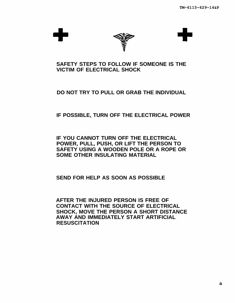
SAFETY STEPS TO FOLLOW IF SOMEONE IS THEVICTIM OF ELECTRICAL SHOCK
DO NOT TRY TO PULL OR GRAB THE INDIVIDUAL
IF POSSIBLE, TURN OFF THE ELECTRICAL POWER
IF YOU CANNOT TURN OFF THE ELECTRICALPOWER, PULL, PUSH, OR LIFT THE PERSON TOSAFETY USING A WOODEN POLE OR A ROPE ORSOME OTHER INSULATING MATERIAL
SEND FOR HELP AS SOON AS POSSIBLE
AFTER THE INJURED PERSON IS FREE OFCONTACT WITH THE SOURCE OF ELECTRICALSHOCK, MOVE THE PERSON A SHORT DISTANCEAWAY AND IMMEDIATELY START ARTIFICIALRESUSCITATION
a
WARNING
All specific cautions and warnings contained in this manual shall be strictlyadhered to. Otherwise, severe injury, death and/or damage to the equipmentmay result.
HIGH VOLTAGE
is produced when this power plant
DEATH
is in operation.
or severe burns may result if personnel fail to observe safety precautions. Donot operate this power plant until the ground terminal studs have beenconnected to a suitable ground. Disconnect the battery ground cable on thegenerator set before removing and installing components on the engine or inthe electrical control panel system. Remove all rings, watches, and otherjewelry when performing maintenance on this equipment. Loose fittingclothing should be secured to prevent it catching in moving parts. Do notattempt to service or otherwise make any adjustments, connections or recon-nections of wires or cables until generator set is shut down and completelyde-energized.
DANGEROUS GASES
Batteries generate explosive gas during charging: therefore, utilize extremecaution. Do not smoke, or use open flame in the vicinity of the generator setswhen servicing batteries.
Exhaust discharge contains noxious and deadly fumes. Do not operate powerplant generator sets in enclosed areas unless exhaust discharge is properlyvented to the outside.
To avoid sparking between filler nozzle and fuel tank, always maintain metal tometal contact between filler nozzle and fuel tank when filling generator set fueltanks.
Do not smoke or use open flame in the vicinity of the power plant while fuelinggenerator sets.
LIQUIDS UNDER HIGH PRESSURE
are generated as a result of operation of the power plant generator sets. Donot expose any part of the body to a high pressure leak in the fuel injectionsystem.
NOISE
Operating noise level of the generator set can cause hearing damage. Earprotectors, as recommended by the medical or safety officer, must be wornwhen working near this power plant.
TM 5-6115-629-14&P
b
TM 5-6115-629-14&P
WARNING
Clean parts in a well-ventilated area. Avoid inhalation of solvent fumes andprolonged exposure of skin to cleaning solvent. Wash exposed skin thorough-ly. Dry cleaning solvent (P-D-680) used to clean parts is potentially danger-ous to personnel and property. Do not smoke or use near open flame or exces-sive heat. Flash point of solvent is 100°F. to 138°F. (38°C. to 59°C.).
c/(d blank)
*TM 5-6115-629-14&P
TECHNICAL MANUAL HEADQUARTERSDEPARTMENT OF THE ARMY
NO. 5-6115-629-14&P WASHINGTON, D.C., 17 June 1988
Operator, Unit, Intermediate Direct Support andIntermediate General Support Maintenance Manual
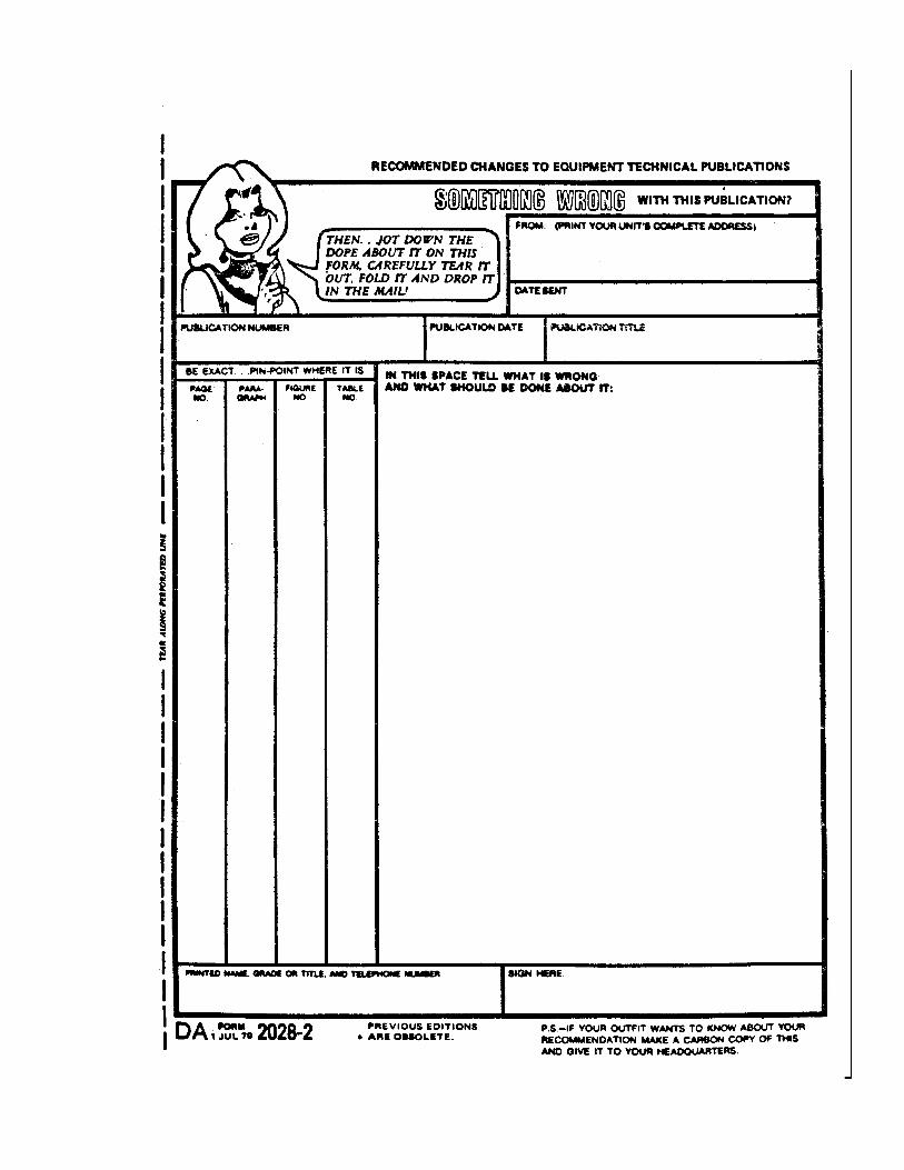
You can help improve this manual. If you find any mistakes, or if you know of a way to improve these procedures, pleaselet us know. Mail your letter or DA Form 2028 (Recommended Changes to Publications and Blank Forms), or DA Form2028-2 located in the back of this manual directly to: Commander, US Army Aviation and Troop Command, ATTN:AMSAT-I-MP, 4300 Goodfellow Blvd., St. Louis, MO 63120-1798. You may also submit your recommended changes byE-mail directly to <mpmtO/[email protected]>. A reply will be furnished directly to you. Instructions forsending an electronic 2028 may be found at the back of this manual immediately preceding the hard copy 2028.
DISTRIBUTION STATEMENT A: Approved for public release; distribution is unlimited
TABLE OF CONTENTSPAGE
CHAPTER 1 INTRODUCTIONSection I General ..................................................................................................................................... 1-1Section II Description and Data . .............................................................................................................. 1-2
CHAPTER 2 OPERATING INSTRUCTIONSSection I Operating Procedures............................................................................................................... 2-1Section II Operation of Auxiliary Equipment ............................................................................................. 2-2Section III Operation Under Unusual Conditions ....................................................................................... 2-2
CHAPTER 3 OPERATOR/CREW MAINTENANCE INSTRUCTIONSSection I Consumable Operating and Maintenance Supplies ................................................................. 3-1Section II Lubrication Instructions............................................................................................................. 3-1Section III Preventive Maintenance Checks and Services (PMCS)........................................................... 3-1Section IV Troubleshooting ........................................................................................................................ 3-20Section V Operator/Crew Maintenance Instructions ................................................................................. 3-20
*This manual supersedes Chapter 11 of TM 5-6115-594-14&P dated 25 September 1984.
Change 3 i
TM 5-6115-629-14&P
CHAPTER 4 UNIT MAINTENANCESection I Service Upon Receipt of Equipment ........................................................................................ 4-1Section II Movement to a New Worksite................................................................................................... 4-7Section III Repair Parts, Special Tools, Special Test,
Measurement and Diagnostic Equipment (TMDE)............................................................. 4-8Section IV Lubrication Instructions............................................................................................................. 4-8Section V Preventive Maintenance Checks and Services ........................................................................ 4-9Section VI Troubleshooting ........................................................................................................................ 4-14Section VII Radio Interference Suppression ............................................................................................... 4-16Section VIII Maintenance of Power Plant Trailer.......................................................................................... 4-16Section IX Maintenance of Electrical System............................................................................................. 4-27
CHAPTER 5 INTERMEDIATE (FIELD) DIRECT SUPPORT AND GENERALSUPPORT MAINTENANCE INSTRUCTIONS
Section I Introduction . ............................................................................................................................. 5-1Section II Maintenance of Power Plant Trailers........................................................................................ 5-1Section III Generator Set ........................................................................................................................... 5-2Section IV Maintenance of Electrical System............................................................................................. 5-5
CHAPTER 6 TEST AND INSPECTION AFTER REPAIRSection I General Requirements.............................................................................................................. 6-1Section II Inspection ................................................................................................................................. 6-1Section III Operational Tests ..................................................................................................................... 6-1
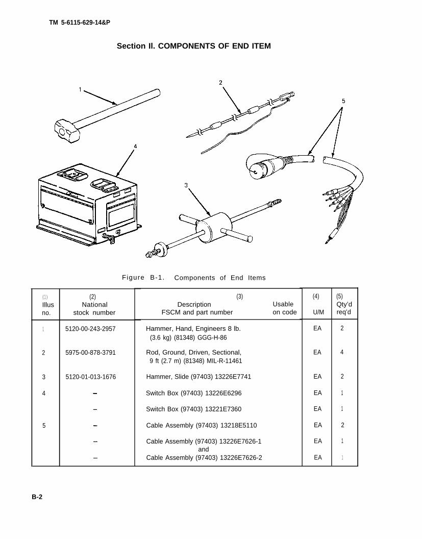
APPENDIX A REFERENCES ......................................................................................................................... A-1APPENDIX B COMPONENTS OF END ITEM AND BASIC ISSUE ITEMS LISTS. ....................................... B-1APPENDIX C MAINTENANCE ALLOCATION CHART .................................................................................. C-1APPENDIX D UNIT, INTERMEDIATE (FIELD) (DIRECT SUPPORT AND GENERAL
SUPPORT) AND DEPOT MAINTENANCE REPAIR PARTSAND SPECIAL TOOLS LIST.............................................................................................. D-1
1-1. Scope. This manual is for your use in operating and maintaining the Power Plant, AN/MJQ-12A. The AN/MJQ-12A is a mobile power plant used to supply power to any system or equipment requiring up to 60 KW of 60 Hz inputoperating power. In addition to operating instructions and operator, unit, and intermediate direct support and generalsupport maintenance procedures, this manual contains a Repair Parts and Special Tools List for the power plant.
1-2. Limited Applicability. Some portions of this publication are not applicable to both services. These portions areprefixed to indicate the service to which they pertain: (A) for Army, and (F) for Air Force. Portions not prefixed areapplicable to both services.
1-3. Maintenance Forms and Records.
a. (A) Maintenance forms and records used by Army personnel are prescribed by DA Pam 738-750.
b. (F) Maintenance forms and records used by Air Force personnel are prescribed in AFM66-1 and theapplicable 00-20 Series Technical Orders.
1-4. Reporting of Errors. Reporting of errors and omissions and recommendations for improvement of thispublication by the individual user is encouraged. Reports should be submitted as follows:
a. (A) Army - DA Form 2028 directly to: Commander, US Army Aviation and Troop Command, ATTN:AMSAT-I-MT, 4300 Goodfellow Boulevard, St. Louis, MO 63120-1798.
b. (F) Air Force - AFTO Form 22 directly to: Commander, Sacramento Air Logistics Center, ATTN:SM-ALC-MMEDTA, McClellan Air Force Base, CA, 95652-5609, in accordance with TO-00-5-1.
1-5. Reporting Equipment Improvement Recommendations (EIR). EIR’s will be prepared using SF368, ProductQuality Deficiency Report. Instructions for preparing EIR’s are provided in DA PAM 738-750, The Army MaintenanceManagement System. EIR’s should be mailed directly to: Commander, US Army Aviation and Troop Support Command,ATTN: AMSAT-I-MDO, 4300 Goodfellow Boulevard, St. Louis, MO 63120-1798.
1-6. Levels of Maintenance Accomplishment.
a. (A) Army users shall refer to the Maintenance Allocation Chart (MAC) for tasks and levels of maintenance tobe performed
b. (F) Air Force users shall accomplish maintenance at the user level consistent with their capability inaccordance with policies established in AFM 66-1.
1-7. Destruction of Army Materiel. Destruction of Army materiel to prevent enemy use shall be in accordance withTM 750-244-3.
1-8. Administrative Storage.
a. Army equipment placed in administrative storage will have preventative maintenance performed inaccordance with the PMCS tables before storage. When equipment is removed from storage, PMCS will beperformed to ensure operational readiness.
Change 3 1-1
TM 5-6115-629-14&P
b. (F) For administrative storage procedures for Air Force equipment, refer to TO 35-1-4, Processing andInspection of Aerospace Ground Equipment for Storage and Shipment.
1-9. Preparation for Shipment and Storage.
a. (A) Army - Refer to TB 740-97-2.b. (F) Air Force - Refer to TO 35-1-4 for component of end item generator sets and TO 38-1-5 for installed
engine.
Section II. DESCRIPTION AND DATA
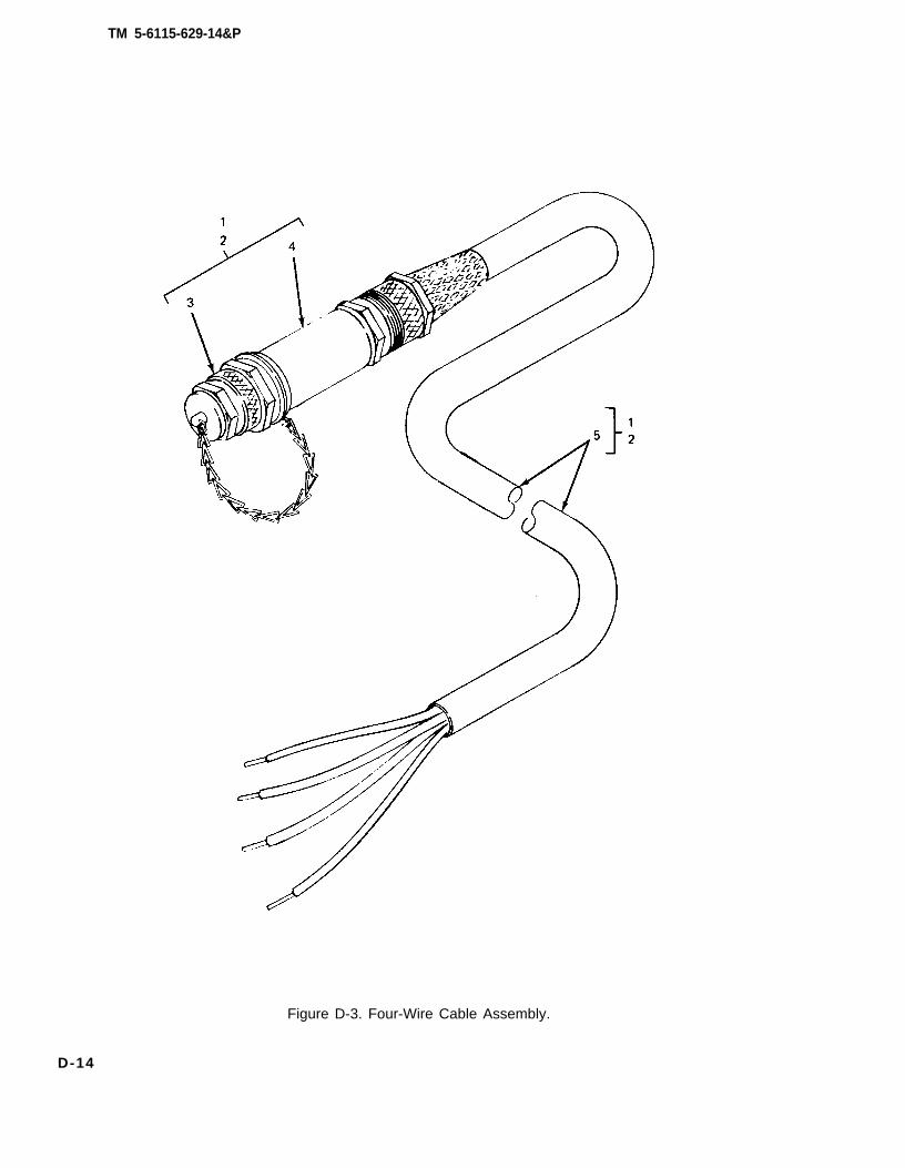
1-10. Description. Power Plant AN/MIJQ-12A is made up of two PU-650B/G power units. Each power unit is, in turn,made up of one Tactical Utility Generator Set, DOD Model MEP-006A mounted on a modified M200A1 trailer. Thesegenerator sets are liquid-cooled, diesel engine-driven units, each with a load capacity of 60KW at 60 Hz. The trailers aretwo-wheeled units with dual tires mounted. Each trailer has a 2 1/2 ton carrying capacity. The modifications to the basictrailers provide stowage for the accessories and all equipment necessary for mobile operation as well as providing a workplatform for the operator and maintenance personnel. Output from the power plant is applied to the system or equipmentbeing powered through a switch box. The AN/MJQ-12A is supplied with either a 4-wire or a 5-wire configuration switchbox. Figures 1-1 and 1-2 illustrate the power plant.
1-2 Change 3
TM 5-6115-629-14&P
Figure 1-1. Power Plant, Curbside Front, Three-Quarter View.
1-3
TM 5-6115-629-14&P
Figure 1-2. Power Plant, Roadside Rear, Three-Quarter View.
1-4
TM 5-6115-629-14&P
1-11. Tabulated Data. The tabulated data provides operator and unit level personnel with the dimen-sions and weights for Power Plant, AN/MJQ-12A. These specifications are computed from the com-bined dimensions and weights of the two power units that make up the power plant. Specifications for asingle PU-650B/G power unit can be found in TM 5-6115-594-14&P. For additional information con-cerning Generator Set DOD Model MEP-006A, refer to TM 5-6115-545-12, – 34, and – 24P. Foradditional information on the M200A1 trailer, refer to TM 9-2330-205-14&P. The tabulated data alsoincludes the location and content of all data plates unique to the power plant.
a. Identification, Information, and Warning Plates.
(1) Modification identification p/ate.
(a) Location. This plate is located on front roadsideIunette.
(b) Content.
MODIFIED FOR POWER PLANT AN/MJQ-12A
frame between the trailer body and
NSN 6115-00-464-4194UNIT A (or B, as applicable)
(2) Identification p/ate.
(a) Location. This plate is located on front curbside frame between trailer body and Iunette.
(a) Location. This plate is located below ground stud above curbside front step.
(b) Content.GROUND TERMINAL
(4) Wiring diagram designation plate.
(a) Location. This plate is located inside switch box access cover.
(b) Contents. (See figure 4-14 or 4-15).
(5) Identification p/ate.
(a) Location. This plate is located on connector side of switch box.
(b) Content.
1-5
ARMY TM 5-6115-629-14&PAIR FORCE TO-35C2-3-488-1
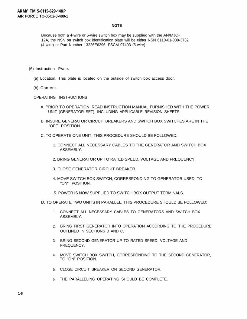
NOTE
Because both a 4-wire or 5-wire switch box may be supplied with the AN/MJQ-12A, the NSN on switch box identification plate will be either NSN 6110-01-038-3732(4-wire) or Part Number 13226E6296, FSCM 97403 (5-wire).
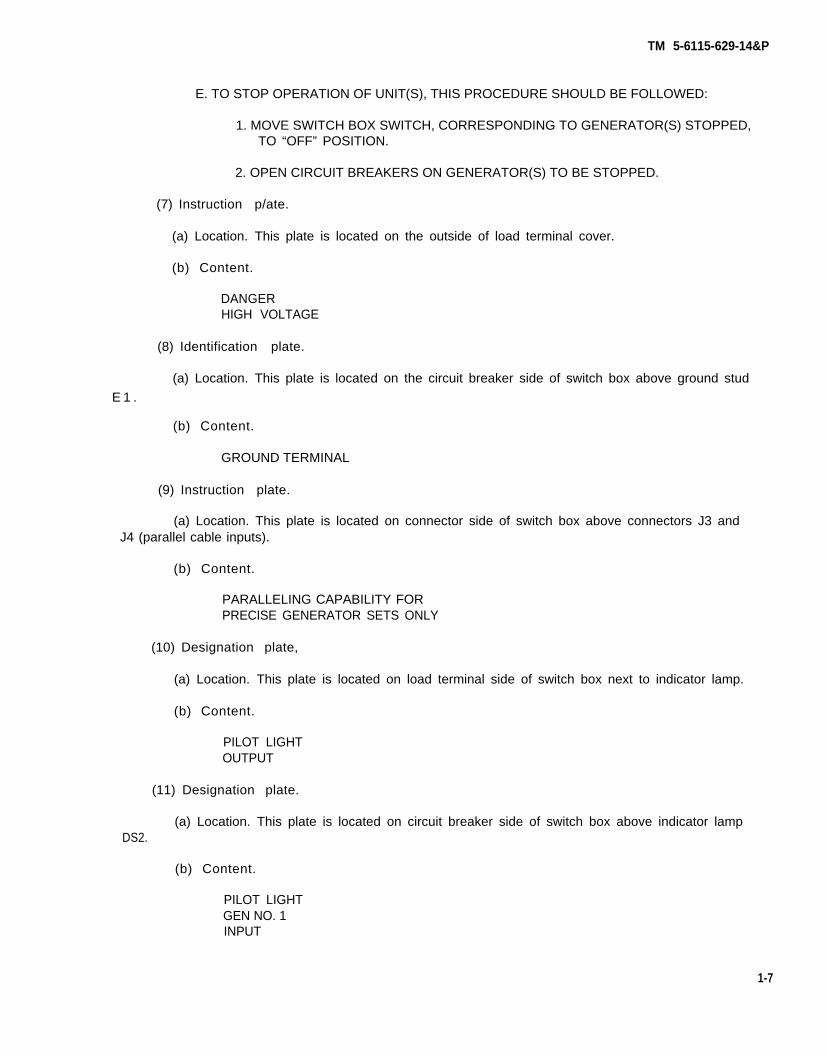
(6) Instruction P/ate.
(a) Location. This plate is located on the outside of switch box access door.
(b) Content.
OPERATING INSTRUCTIONS
A. PRIOR TO OPERATION, READ INSTRUCTION MANUAL FURNISHED WITH THE POWERUNIT (GENERATOR SET), INCLUDING APPLICABLE REVISION SHEETS.
B. INSURE GENERATOR CIRCUIT BREAKERS AND SWITCH BOX SWITCHES ARE IN THE“OFF” POSITION.
C. TO OPERATE ONE UNIT, THIS PROCEDURE SHOULD BE FOLLOWED:
1. CONNECT ALL NECESSARY CABLES TO THE GENERATOR AND SWITCH BOXASSEMBLY.
2. BRING GENERATOR UP TO RATED SPEED, VOLTAGE AND FREQUENCY.
1-12. Differences Between Models. There are no differences between models, serial numbers, orserial number groups applicable to this equipment.
1-9/(1-10 blank)
TM 5-6115-629-14&P
CHAPTER 2
OPERATING INSTRUCTIONS
Section l. OPERATING PROCEDURES
2.1. Power Plant Operating Procedures. The typical mission for any mobile power generatingequipment can be described in three steps or phases. In the first phase, the power plant is towed tothe worksite and installed by unit level technicians (paragraph 4-2). In the second phase of themission, the operator starts the generator sets, runs them to power a system or equipment, andeventually shuts them down. In the final phase, the power plant is dismantled, packed up and eithermoved to a new worksite or returned to standby status (paragraph 4-3). This final phase is alsoaccomplished by unit level technicians.
a. Generator Set Operating Procedures.
WARNING
Do not operate power plant generator set(s) until properly grounded(paragraph 4-2, b.) Serious injury or death by electrocution can result fromoperating an ungrounded generator set.
Operating noise level of generator sets can cause hearing damage. Earprotectors, as recommended by medical or safety officer, must be worn whenworking near power plant.
CAUTION
To avoid damage to equipment, make certain of voltage, frequency, andphase requirements of load connected to power plant.
NOTE
Before starting generator set, do your Before PMCS as described in table 3-2.
Detailed procedures for prestarting, starting, operating, and shutting down the power plant generatorsets are found in TM 5-6115-545-12 and on the Operating Instruction data plates found on the equip-ment. Refer to the data plate, located inside the right hand control panel door, to start and run thegenerator sets. Monitor and adjust power output as required during operation. At the end of themission, shut down the generator sets in accordance with the operating instructions on the data plate.
b. Switch Box Operating Procedures. Start and stop generator sets in accordance with paragraph2-1, a., when instructed to do so in the following procedures.
CAUTION
Close all doors on generator sets except doors over control panels andlouvers.
(1) Set circuit breakers on both power plant generator sets to OFF position.
(2) Set both switches on switch box to OFF position.
2-1
TM 5-6115-629-14&P
(3)
(4)
(5)
(6)
(7)
(8)
(9)
(10)
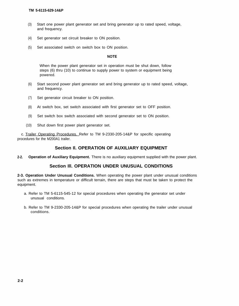
Start one power plant generator set and bring generator up to rated speed, voltage,and frequency.
Set generator set circuit breaker to ON position.
Set associated switch on switch box to ON position.
NOTE
When the power plant generator set in operation must be shut down, followsteps (6) thru (10) to continue to supply power to system or equipment beingpowered.
Start second power plant generator set and bring generator up to rated speed, voltage,and frequency.
Set generator circuit breaker to ON position.
At switch box, set switch associated with first generator set to OFF position.
Set switch box switch associated with second generator set to ON position.
Shut down first power plant generator set.
c. Trailer Operating Procedures. Refer to TM 9-2330-205-14&P for specific operatingprocedures for the M200A1 trailer.
Section Il. OPERATION OF AUXILIARY EQUIPMENT
2-2. Operation of Auxiliary Equipment. There is no auxiliary equipment supplied with the power plant.
Section Ill. OPERATION UNDER UNUSUAL CONDITIONS
2-3. Operation Under Unusual Conditions. When operating the power plant under unusual conditionssuch as extremes in temperature or difficult terrain, there are steps that must be taken to protect theequipment.
a. Refer to TM 5-6115-545-12 for special procedures when operating the generator set underunusual conditions.
b. Refer to TM 9-2330-205-14&P for special procedures when operating the trailer under unusualconditions.
2-2
TM 5-6115-629-14&P
CHAPTER 3
OPERATOR/CREW MAINTENANCE INSTRUCTIONS
Section I. CONSUMABLE OPERATING AND MAINTENANCE SUPPLIES
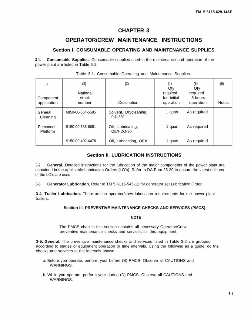
3-1. Consumable Supplies. Consumable supplies used in the maintenance and operation of thepower plant are listed in Table 3-1.
Table 3-1. Consumable Operating and Maintenance Supplies.
(1) (2) (3) (4) (5) (6)Qty Qty
National required requiredComponent stock for initial 8 hoursapplication number Description operation operation Notes
General 6850-00-664-5685 Solvent, Drycleaning, 1 quart As requiredCleaning P-D-680
Personnel 9150-00-186-6681 Oil, Lubricating, 1 quart As requiredPlatform OE/HDO-30
9150-00-402-4478 Oil, Lubricating, OEA 1 quart As required
Section II. LUBRICATION INSTRUCTIONS
3-2. General. Detailed instructions for the lubrication of the major components of the power plant arecontained in the applicable Lubrication Orders (LO’s). Refer to DA Pam 25-30 to ensure the latest editionsof the LO’s are used.
3-3. Generator Lubrication. Refer to TM 5-6115-545-12 for generator set Lubrication Order.
3-4. Trailer Lubrication. There are no operator/crew lubrication requirements for the power planttrailers.
Section Ill. PREVENTIVE MAINTENANCE CHECKS AND SERVICES (PMCS)
NOTE
The PMCS chart in this section contains all necessary Operator/Crewpreventive maintenance checks and services for this equipment.
3-5. General. The preventive maintenance checks and services listed in Table 3-2 are groupedaccording to stages of equipment operation or time intervals. Using the following as a guide, do thechecks and services at the intervals shown.
a. Before you operate, perform your before (B) PMCS. Observe all CAUTIONS andWARNINGS.
b. While you operate, perform your during (D) PMCS. Observe all CAUTIONS andWARNINGS.
3-1
TM 5-6115-629-14&P
c. After you operate, be sure to perform your after (A) PMCS.
d. Do (W) PMCS weekly.
e. Do (M) PMCS monthly.
f. If equipment fails to operate, refer to Section IV Troubleshooting. If the problem cannot becorrected, see paragraph 3-8, Reporting Deficiencies.
3-6. Purpose of PMCS Table. The purpose of the PMCS table is to provide a systematic method ofinspecting and servicing the equipment. In this way, small defects can be detected early before theybecome a major problem causing the equipment to fail to complete its mission. The PMCS table isarranged with the individual PMCS procedures listed in sequence under assigned intervals. The mostlogical time (before, during, or after operation) to perform each procedure determines the interval towhich it is assigned. Make a habit of doing the checks and services in the same order each time andanything wrong will be seen quickly. See paragraph 3-7 for an explanation of the columns intable 3-2.
3-7. Explanation of Columns. The following is a list of the PMCS table column headings with adescription of the information found in each column.
a. Item No. This column shows the sequence in which the checks and services are to beperformed, and is used to identify the equipment area on the Equipment Inspection and MaintenanceWorksheet, DA Form 2404.
b. Interval. This column shows when each check is to be done.
c. Item to be inspected. This column identifies the general area or specific part where the checkor service is to be done.
d. Procedures. This column lists the checks or services to be done and explains how to do them.
e. Equipment is Not Ready/AvaiIable If. This column lists conditions that make the equipmentunavailable for use because it is unable to perform its mission or because it would represent a safetyhazard. Do not accept or operate equipment with a condition in the “Equipment is Not Ready/AvailableIf” column.
3-8. Reporting Deficiencies. If you discover any problem with the equipment during PMCS or whileoperating it that you are unable to correct, it must be reported. Refer to DA Pam 738-750 and reportthe deficiency using the proper forms.
3-9. Special Instructions. Preventive maintenance is not limited to performing the checks andservices listed in the PMCS table. Covering unused receptacles, stowing unused equipment and otherroutine procedures such as equipment inventory, cleaning components, and touch-up painting arenot listed in the PMCS table. These are things you should do any time you see they need to be done. Ifa routine check is listed in the PMCS table it is because other operators have reported problems withthis item. Take along tools and cleaning cloths needed to perform the required checks and services.Use the information in the following paragraphs to help you identify problems at any time.
a. Routine Inspections. Use the following information to help identify potential problems beforeand during checks and services.
3-2
TM 5-6115-629-14&P
WARNING
(1)
(2)
(3)
(4)
(5)
Drycleaning solvent P-D-680 is both toxic and flammable. Wear safety gogglesand gloves and use in a well-ventilated area. Avoid prolonged breathing ofvapors and avoid skin contact. Do not smoke or use near open flame orexcessive heat. Flash point of solvent is 100°F to 138°F (38°C to 59°C). If youbecome dizzy while using P-D-680, get fresh air immediately and get medicalaid. If P-D-680 contacts eyes, flush with water and get medical aidimmediately.
Keep it clean. Dirt, grease, and oil get in the way and may cover up a serious problem.Use drycleaning solvent P-D-680, to clean metal surfaces. Use soap and water to cleanrubber or plastic parts and material.
Bolts, nuts, and screws. Check them all to make sure they’re not lose, missing, bent, orbroken. Don’t try to check them all with a tool, but look for chipped paint, bare metal, orrust around bolt heads. If you find one loose, tighten it or report it to unit maintenance.
Welds. Look for loose or chipped paint, rust, or gaps where parts are welded together.If a broken weld is found, report it to higher level of maintenance.
Electrical wires, connectors, terminals and receptacles. Look for cracked or brokeninsulation, bare wires, and loose or broken connectors. Tighten loose connectors andmake sure the wires are in good condition. Examine terminals and receptacles forserviceability.
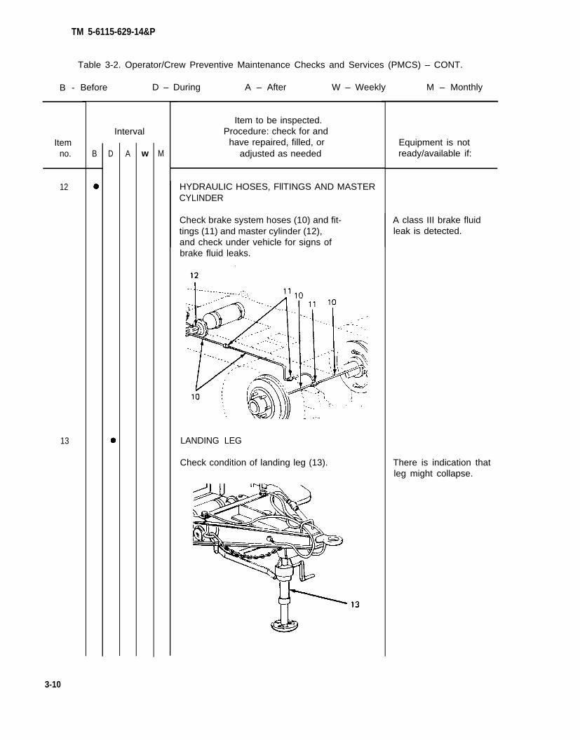
Hoses and fluid lines. Look for wear, damage, and leaks. Make sure clamps and fittingsare tight. Wet spots and stains around a fitting or connector can mean a leak. If a leakcomes from a loose connector, tighten it. If something is broken or worn out, report it tounit maintenance.
b. Leakage Definitions. It is necessary for you to know how fluid leakage affects the status of yourequipment. The following are definitions of the types/classes of leakage you need to know to be ableto determine the status of your equipment. Learn and be familiar with them. When in doubt, NOTIFYYOUR SUPERVISOR!
Leakage Definitions:
Class I Seepage of fluid (as indicated by wetness or discoloration) not greatenough to form drops.
Class II Leakage of fluid great enough to form drops but not enough to causedrops to drip from item being checked/inspected.
Class III Leakage of fluid great enough to form drops that fall from the itembeing checked/inspected.
3-3
TM 5-6115-629-14&P
CAUTION
Equipment operation is allowable with minor leakage (Class I or II) of any fluidexcept fuel. Of course, consideration must be given to the fluid capacity in theitem being checked/inspected. When in doubt, notify your supervisor.
When operating with Class I or II leaks, continue to check fluid level more oftenthan required in the PMCS. Parts without fluid will stop working and/or causeequipment damage.
Class III leaks should be reported to your supervisor or unit maintenance.
NOTE
If the equipment must be kept in continuous operation, check and service onlythose items that can be checked and serviced without disturbing operation.Make the complete checks and services when the equipment can be shutdown.
Within designated interval, these checks are to be performed in the orderlisted.
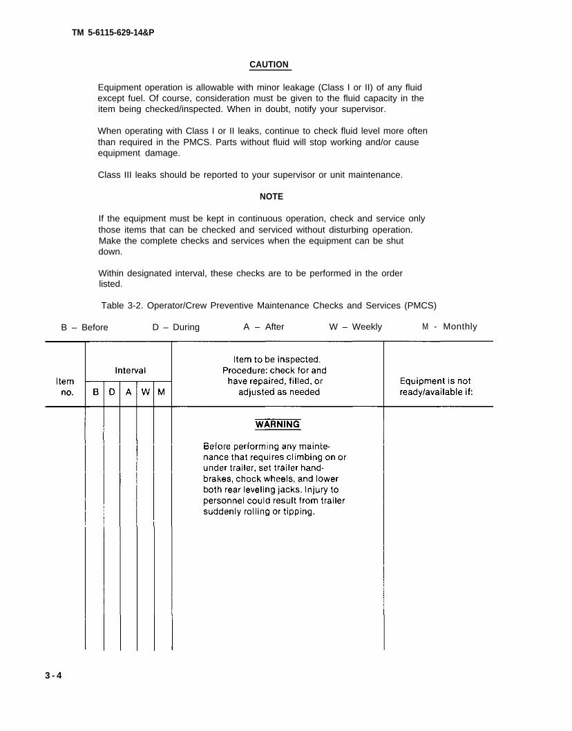
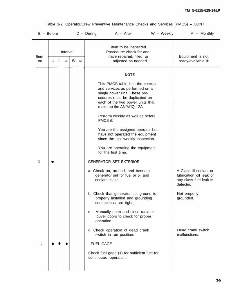
Table 3-2. Operator/Crew Preventive Maintenance Checks and Services (PMCS)
B – Before D – During A – After W – Weekly M - Monthly
This PMCS table lists the checksand services as performed on asingle power unit. These pro-cedures must be duplicated oneach of the two power units thatmake up the AN/MJQ-12A.
Perform weekly as well as beforePMCS if:
You are the assigned operator buthave not operated the equipmentsince the last weekly inspection.
You are operating the equipmentfor the first time.
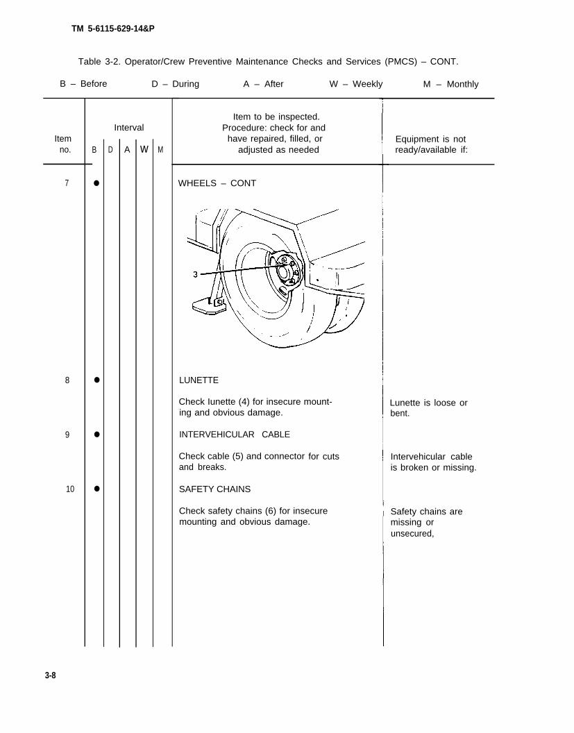
1 GENERATOR SET EXTERIOR
a. Check on, around, and beneathgenerator set for fuel or oil andcoolant leaks.
b. Check that generator set ground isproperly installed and groundingconnections are tight.
c. Manually open and close radiatorlouver doors to check for properoperation.
d. Check operation of dead crankswitch in run position.
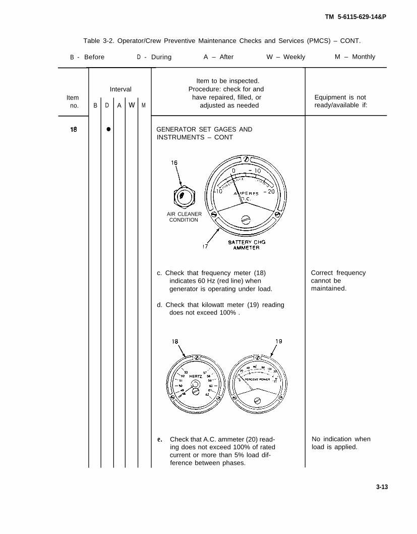
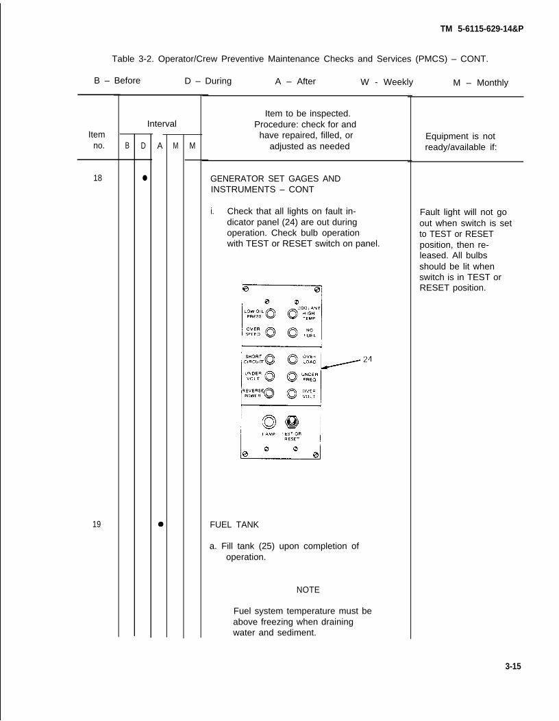
2 FUEL GAGE
Check fuel gage (1) for sufficient fuel forcontinuous operation.
Equipment is notready/available if:
A Class III coolant orlubrication oil leak orany class fuel leak isdetected.
Push in on lens housing. Light (30) shouldilluminate. If not, replace bulb.
CIRCUIT BREAKER INDICATOR LIGHT
Push in on lens housing. Light (31) shouldilluminate. If not, replace bulb.
BRAKE DRUMS AND HUBS
WARNING
A defect in the operation of thebrakes or hub can cause theseparts to get hot enough to causeserious burns. Use extreme cau-tion when attempting to detectheat in this area.
Feel drums and hubs for overheating.
AIR RESERVOIR
Open draincock (32) to drain moisturefrom air reservoir (33) and close whenfinished.
Equipment is notready/available if:
Brakes or hub aredragging or binding.
3-17
TM 5-6115-629-14&P
Table 3-2. Operator/Crew Preventive Maintenance
B – Before D – During A – After
Itemno.
24
25
3-18
B
Interval
D A
●
●
w M
Checks and Services (PMCS) – CONT.
W – Weekly M – Monthly
Item to be inspected.Procedure: check for and
have repaired, filled, oradjusted as needed
AIR RESERVOIR – CONT
HANDBRAKES
With trailer hooked to towing vehicle,set handbrakes (34). Move trailerslightly to see if handbrakes holdwheels. Adjust as required.
Item to be inspected.Procedure: check for andhave repaired, filled, or
adjusted as needed.
REFLECTORS
Check for damaged or missing reflectors.
BATTERIES
Check battery (35) electrolyte level. Levelshould be about 3/4 inch above top ofplates. Add water if level is low. Useclean water (distilled water if available).
FIRE EXTINGUISHER
Inspect and weigh fire extinguisher.(See paragraph 3-11.)
TRAILER FRAME
Inspect entire chassis frame for damage,cracks, and broken welds.
COOLANT LEVEL
Check level of fluid in cooling system.Proper level is 2 inches below overflowpipe. Add coolant as required.
M – Monthly
Equipment is notready/available if:
Frame is obviouslybroken or cracked.
Change 1 3-19
TM 5-6115-629-14&P
Section IV. TROUBLESHOOTING
3-10. Power Unit Troubleshooting. There are no troubleshooting procedures authorized at operatorlevel for the power plant end item. Troubleshooting procedures for the individual generator sets andtrailers are contained in their respective technical manuals referenced below.
a. Generator Set Troubleshooting. Refer to TM 5-6115-545-12 for troubleshooting proceduresapplicable to the generator set.
b. Trailer Troubleshooting. Refer to TM 9-2330-205-14&P for troubleshooting proceduresapplicable to the trailer.
Section V. OPERATOR/CREW MAINTENANCE
3-11. Fire Extinguisher Maintenance. The AN/MJQ-12A Power Plant is equipped with two 5 lb C02
fire extinguishers. Maintenance is limited to weighing the fire extinguishers monthly to insure that theyare sufficiently charged. Fully charged, each fire extinguisher weighs 13 lbs. Send the unit tospecialized activity for recharging if it weighs 12.5 lb or less.
CAUTION
Do not attempt to verify readiness of a fire extinguisher by partially dischargingunit. Any discharge of contents will require refilling.
3-20
TM 5-6115-629-14&P
CHAPTER 4
UNIT MAINTENANCE
Section I. SERVICE UPON RECEIPT OF EQUIPMENT
4-1. Inspecting and Servicing Equipment. The power plant is unpacked, inspected, and serviced asdescribed in the following paragraphs. Unpacked equipment must be checked against the EquipmentPacking List to ensure completeness. Discrepancies must be reported in accordance with instructionsin DA Pam 738-750.
a. Unpacking Power Plant. (See figures 4-1 and 4-2.) The two power units that make up theAN/MJQ-12A power plant are identical except for the addition of the switch box installed on the curb-side fender of one of the units. Therefore, the unpacking procedures are typical for both. Each gen-erator set is packed in place on its respective trailer. Before beginning the unpacking procedure,locate and remove Depreservation Guide.
Figure 4-1. Power Unit B, with Switch BOX, Packed for Shipment.
4-1
TM 5-6115-629-14&P
WARNING
The steel banding used in packaging of power plant has sharp edges. Careshould be taken when cutting and handling banding to avoid injury topersonnel.
(1) Remove steel banding around plywood box(es) covering generator set and, whenunpacking unit B, the switch box.
(2) Remove lag screws securing plywood box cover over generator set and lift off cover.
(3) Remove wooden wedges and spacers from around generator set base. Loosen switch boxattaching hardware and remove any steel banding remaining beneath switch box.
Figure 4-2. Unpacking Power Plant – Power Unit B Shown.
(4) Remove and save package of technical manuals secured to barrier material.
(5) Remove four sets of attaching hardware and drop plywood cover under trailer.
(6) Remove barrier material and fiberboard caps from generator set.
4-2
TM 5-6115-629-14&P
(7) Remove packaged fire extinguisher from within generator set enclosure. Unpack andsecure fire extinguisher in bracket on front roadside step.
(8) Remove steel banding around accessory box, unpack and inventory contents.
(9) Refer to DA Form 2258, Depreservation Guide for Vehicles and Equipment, packed withpower unit and follow instructions given for putting unit into service.
(10) Stow technical manuals in box on inside of generator set enclosure rear curbside door.
(11) Stow all authorized accessories in the accessory box.
(12) Remove all tape and packing film from trailer air hoses and intervehicular cable.
b. Inspection and Servicing of Generator Set. Refer to Service Upon Receipt of Materiel in TM5-6115-545-12 for initial inspection and servicing procedures.
c. Inspection and Servicing of Trailers. Refer to Service Upon Receipt of Materiel in TM 9-2330-205-14&P for initial inspection and servicing procedures.
4-2. Installation. (See figure 4-3.) Installation of the power plant at a worksite involves positioningboth the power unit trailers and the switch box, and grounding the equipment.
a. Positioning Power Plant. Position the power plant on the worksite as follows:
(1)
(2)
(3)
(4)
(5)
(6)
(7)
(8)
(9)
Select an area as level as possible to install power plant and position both power units.
Set handbrakes and lower landing legs on both trailers.
Chock both sets of dual wheels on each trailer.
Lower both rear leveling jacks on each trailer and secure leveling jacks with Iockpins.Extend lower tubes on leveling jacks by stepping on hinged pads.
WARNING
Remove fire extinguishers and fuel cans from individual power units whenpower plant is in operation. This will insure that in the event of fire, extra fuelwill not be involved and extinguishers will remain accessible.
Locate fuel cans and fire extinguishers on ground halfway between the two power units.
Remove switch box from fender of power unit B and stow attaching hardware in accessorybox.
Position switch box assembly on ground halfway between two power units.
Connect one ground wire to GROUND TERMINAL stud on front, roadside frame of eachpower unit trailer. Connect opposite end of both ground wires to GROUND TERMINAL lug onswitch box.
Unstrap and remove power cables from fenders of both power units.
4-3
4-4
TM 5-6115-629-14&P
NOTE
When performing step 10, note that the power cables, the individual wires inthe cables, and the generator set load terminals are all marked foridentification. Make certain these markings correspond when connectingpower cables.
(10) Connect power cable to each generator set load terminal board as follows:
(a) White wire to load terminal L0.
(b) Black wire to load terminal L1.
(c) Red wire to load terminal L2.
(d) Blue wire to load terminal L3.
(11)
(12)
(13)
(14)
Connect both power cables to switch box.
WARNING
Do not operate power plant until both power units have been properly grounded(paragraph 4-2, b.) Serious injury or death by electrocution can result fromoperating an ungrounded power plant.
CAUTION
To avoid damage to equipment, make certain of voltage, frequency,phase requirements of load being connected to power plant.
and
Connect power plant switch box to system or equipment to be powered. Refer toTM 5-6115-545-12 and generator set load terminal board data plate. Data plate is locatedon inside of generator enclosure door nearest load terminals.
Remove quick-release pins securing both power unit personnel platforms and lowerplatforms.
On both power units, open control panel doors and the two doors immediately belowcontrol panels.
the
TM 5-6115-629-14&P
Figure 4-3. Power Plant Installation.
4-5
TM 5-6115-629-14&P
b. Grounding. Check that the individual power unit generator sets are grounded to the GROUNDTERMINAL studs on their respective trailer frames. Using ground wire supplied with power plant,connect GROUND TERMINAL lug on switch box to a suitable ground as described below. The followingsources of a good ground are listed in order of preference.
(1)
(2)
(3)
NOTE
As a substitute for the supplied ground wire, any copper wire of at least No. 6AWG may be used.
Underground water system. Ground power plant to one of the accessible pipes in an under-ground water system. Make certain underground pipe is made of metal and there is no in-sulation, such as a water meter, between ground wire and the earth.
Ground rod. Drive grounding rod a minimum of eight feet into earth. A ground rod musthave a minimum diameter of 5/8-inch, if solid, or 3/4-inch if pipe.
NOTE
It maybe necessary to saturate the area around ground rod with water if soilconditions are dry.
Ground plate. Ground power plant to a metal plate buried four feet deep. Ground plateshould cover a minimum area of nine square feet.
c. External Fuel Line Connection. (See figure 4-4). Either or both of the power units that make upthe power plant can be fueled from an external source. The external source could be a five-gallon fuelcan or a 55-gallon drum. This eliminates the need for frequent refilling of a generator set’s fuel tankduring long intervals of operation.
(1) Remove fuel can adapter and fuel pickup tube from storage locations on power unit andassemble by threading pickup tube into adapter.
(2) Thread one end of auxiliary fuel line onto fuel can adapter fitting and tighten.
(3) Connect free end of auxiliary fuel line to AUXILIARY FUEL CONNECTION. This connection islocated next to the fuel filler above the trailer roadside fender.
(4) Insert fuel can adapter into external fuel source and secure by pressing down on lever.
(5) Set FUEL SELECTOR VALVE beneath fuel filler to AUXILIARY position.
4-6
TM 5-6115-629-14&P
Figure 4-4. External Fuel Line Connection.
Section II. MOVEMENT TO A NEW WORKSITE
4.3. Dismantling for Movement. Because the power plant is designed to be mobile, a minimumamount of effort is required to relocate to a new worksite. Procedures are as follows:
a.
b.
c.
d.
e.
f.
Disconnect power plant from system or equipment being powered.
Disconnect ground cables from source of ground and GROUND TERMINAL studs on both powerunits. Roll up cables and store in accessory boxes.
Using slide hammer, remove ground rods. Disassemble, clean, and stow ground rods inaccessory boxes.
Disconnect power plant from external fuel sources, if applicable.
Disconnect ground wires between switch box and GROUND TERMINAL studs on power units.Roll up ground wires and store in accessory boxes.
Disconnect power cables from both power units and from switch box. Roll up cables andsecure each to roadside fender of respective power unit using straps provided.
4-7
TM 5-6115-629-14&P
g.
h.
i.
j.
k.
l.
m.
n.
o.
Close switch box access door and cap connectors. Position switch box on curbside fender ofpower unit B and secure with hardware provided.
Stow any remaining authorized equipment in accessory box.
Secure fire extinguishers and fuel cans in their respective mounting brackets.
Close all doors on the generator set enclosures.
On each power unit, swing personnel platform up into traveling position and secure with twoplatform anchor quick-release pins.
WARNING
Use care when releasing spring-loaded lower tube of leveling jacks. The lowertube will return to retracted position with considerable force and can causeinjury.
Retract lower tubes of leveling jacks. Swing leveling jacks up into traveling position and securewith Iockpins.
Remove wheel chocks.
Attach power units to towing vehicles. Refer to TM9-2330-205-14&P.
Release trailer handbrakes on both power units.
4-4. Reinstallation After Movement. After movement to a new worksite, install power plant inaccordance with paragraph 4-2.
Section Ill. REPAIR PARTS, SPECIAL TOOLS, SPECIAL TEST, MEASUREMENT ANDDIAGNOSTIC EQUIPMENT (TMDE)
4-5. Tools and Equipment. There are no special tools or equipment required to maintain theAN/MJQ-12A power plant.
4-6. Maintenance Repair Parts. Repair parts and equipment for maintenance of this power plant arelisted and illustrated in the repair parts and special tools list in Appendix D of this manual.
Section IV. LUBRICATION INSTRUCTIONS
4-7. General. Detailed instructions for the lubrication of the major components of the power plant arecontained in the applicable Lubrication Orders (LO’s). Refer to DA Pam 25-30 to ensure that the latest editionsof the L.O.’S are used. This section contains lubrication instructions that are not included in the LubricationOrders.
4-8
4-8.
4-9.
a.
b.trailer
TM 5-6115-629-14&P
Generator Lubrication. Refer to TM 5-6115-545-12 for generator set Lubrication Order.
Trailer Assembly Lubrication.
Trailer Lubrication. Refer to TM 9-2330-205-14&P for trailer Lubrication Order.
Personnel Platform Lubrication. The personnel platform is a modification to the standard M200A1and, as such,
semiannually as follows:
Clean parts
(1)
(2)
does not appear in the associated L.O. Lubricate the
WARNING
in a well-ventilated area. Avoid inhalation of solvent fumesprolonged exposure of skin to cleaning solvent. Wash exposed skin
personnel platform
and
thoroughly. Dry cleaning solvent (P-D-680) used to clean parts is potentiallydangerous to personnel and property. Do not smoke or use near openflame or excessive heat. Flash point of solvent is 100°F to 138°F to 59°
Using P-D-680, or equivalent, clean area to be lubricated.
Apply OE lubricating oil to personnel platform pivot points and to platform anchor quick-release pins.
Section V. PREVENTIVE MAINTENANCE CHECKS AND SERVICES
NOTE
The PMCS chart in this section contains all necessary unit preventivemaintenance checks and services for this equipment.
4-10. General. The trailer assemblies and generator sets must be inspected and serviced systematicallyto insure that the power plant is ready for operation at all times. Inspection will allow defects to bediscovered and corrected before they result in serious damage or failure. Table 4-1 contains a tabulatedlist of preventive maintenance checks and services to be performed by unit maintenance personnel. Allof the unit PMCS on the trailers is scheduled to be performed semiannually, Unit PMCS on the generatorsets is scheduled weekly or on a per-hours-of-operation basis. The running time meters on the controlpanels are used to determine the operating time of the generator sets. Using the following as a guide,do the checks and services at the intervals shown. Observe all CAUTIONS and WARNINGS.
a. For PMCS performed on an operating time basis, perform your hourly (H) PMCS as close aspossible to the time intervals indicated.
NOTE
For units in continuous operation, perform PMCS before starting operationif continuous operation will extend service interval past that which is shown.
b. Perform your weekly (W) PMCS every week or 40 hours of generator set operating time.
c. Perform your monthly (M) PMCS every month or 100 hours of generator set operating time.
d. Do your semiannual (S) PMCS once every six months or 500 hours of generator set operating time.
e. Do your annual (A) PMCS once every year or 1000 hours of generator set operating time.
Change 1 4-9
TM 5-6115-629-14&P
f. If you discover a problem with the equipment, refer to Section Vl, Troubleshooting. If you cannotcorrect the problem, refer to paragraph 4-12, Reporting Deficiencies.
4-11. Explanation of Columns. The following is a list of the PMCS table column headings with a descrip-tion of the information found in each column.
a.
b.
c.
d.
4-12.
Item No. This column shows the sequence in which to do the checks and services, and is usedto identify the equipment area on the Equipment inspection and Maintenance Worksheet,D A F o r m 2 4 0 4 .
Interval. This column shows when each check is to be done.
Item to be Inspected. This column identifies the general area or specific part where the checkor service is to be done.
Procedures. This column lists the checks or service you have to do and explains how to do them.
Reporting Deficiencies. If you discover any problem with the equipment during PMCS that youare unable to correct, It must be reported. Refer to DA Pam 738-750 and report the deficiency usingthe proper forms.
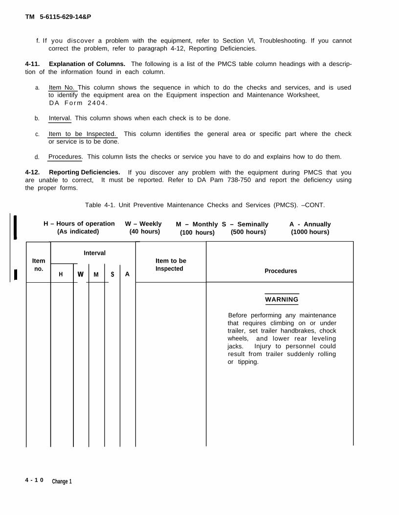
Table 4-1. Unit Preventive Maintenance Checks and Services (PMCS). –CONT.
H – Hours of operation W – Weekly M – Monthly S – Seminally A - Annually(As indicated) (40 hours) (100 hours) (500 hours)- (1000 hours)
Itemno.
H
Interval
w M s A
Item to beInspected Procedures
WARNING
Before performing any maintenancethat requires climbing on or undertrailer, set trailer handbrakes, chockwheels, and lower rear levelingjacks. Injury to personnel couldresult from trailer suddenly rollingor tipping.
4 - 1 0 Change 1
TM 5-6115-629-14&P
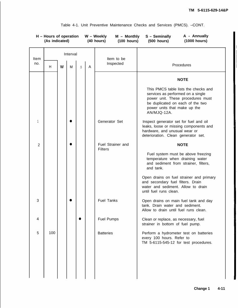
Table 4-1. Unit Preventive Maintenance Checks and Services (PMCS). –CONT.
H – Hours of operation W – Weekly M – Monthly S – Seminally A - Annually(As indicated) (40 hours) (100 hours) (500 hours) (1000 hours)
Itemno.
1
2
3
4
5
H
100
Interval
w M
●
●
●
s
●
A
Item to beInspected
Generator Set
Fuel Strainer andFilters
Fuel Tanks
Fuel Pumps
Batteries
Procedures
NOTE
This PMCS table lists the checks andservices as performed on a singlepower unit. These procedures mustbe duplicated on each of the twopower units that make up theAN/MJQ-12A.
Inspect generator set for fuel and oilleaks, loose or missing components andhardware, and unusual wear ordeterioration. Clean generator set.
NOTE
Fuel system must be above freezingtemperature when draining waterand sediment from strainer, filters,and tank.
Open drains on fuel strainer and primaryand secondary fuel filters. Drainwater and sediment. Allow to drainuntil fuel runs clean.
Open drains on main fuel tank and daytank. Drain water and sediment.Allow to drain until fuel runs clean.
Clean or replace, as necessary, fuelstrainer in bottom of fuel pump.
Perform a hydrometer test on batteriesevery 100 hours. Refer toTM 5-6115-545-12 for test procedures.
Change 1 4-11
TM 5-6115-629-14&P
Itemno.
6
7
8
9
10
11
1 2
13
14
15
16
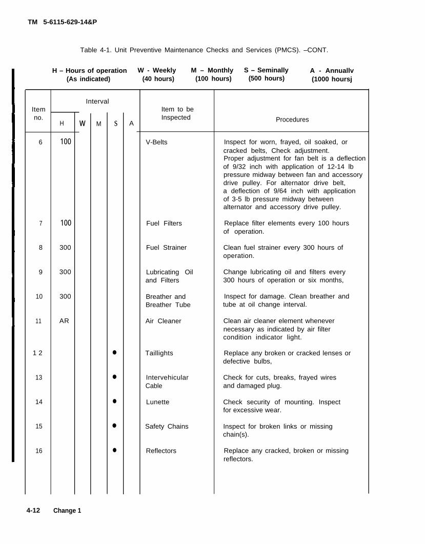
Table 4-1. Unit Preventive Maintenance Checks and Services (PMCS). –CONT.
H – Hours of operation W - Weekly M – Monthly S – Seminally A - Annuallv(As indicated) (40 hours) (100 hours) (500 hours) (1000 hoursj
H
100
100
300
300
300
AR
Interval
w M s
●
●
●
●
●
A
Item to beInspected
V-Belts
Fuel Filters
Fuel Strainer
Lubricating Oiland Filters
Breather andBreather Tube
Air Cleaner
Taillights
IntervehicularCable
Lunette
Safety Chains
Reflectors
Procedures
Inspect for worn, frayed, oil soaked, orcracked belts, Check adjustment.Proper adjustment for fan belt is a deflectionof 9/32 inch with application of 12-14 lbpressure midway between fan and accessorydrive pulley. For alternator drive belt,a deflection of 9/64 inch with applicationof 3-5 lb pressure midway betweenalternator and accessory drive pulley.
Replace filter elements every 100 hoursof operation.
Clean fuel strainer every 300 hours ofoperation.
Change lubricating oil and filters every300 hours of operation or six months,
Inspect for damage. Clean breather andtube at oil change interval.
Clean air cleaner element whenevernecessary as indicated by air filtercondition indicator light.
Replace any broken or cracked lenses ordefective bulbs,
Check for cuts, breaks, frayed wiresand damaged plug.
Check security of mounting. Inspectfor excessive wear.
Inspect for broken links or missingchain(s).
Replace any cracked, broken or missingreflectors.
4-12 Change 1
Itemno.
17
18
19
20
21
22
23
24
TM 5-6115-629-14&P
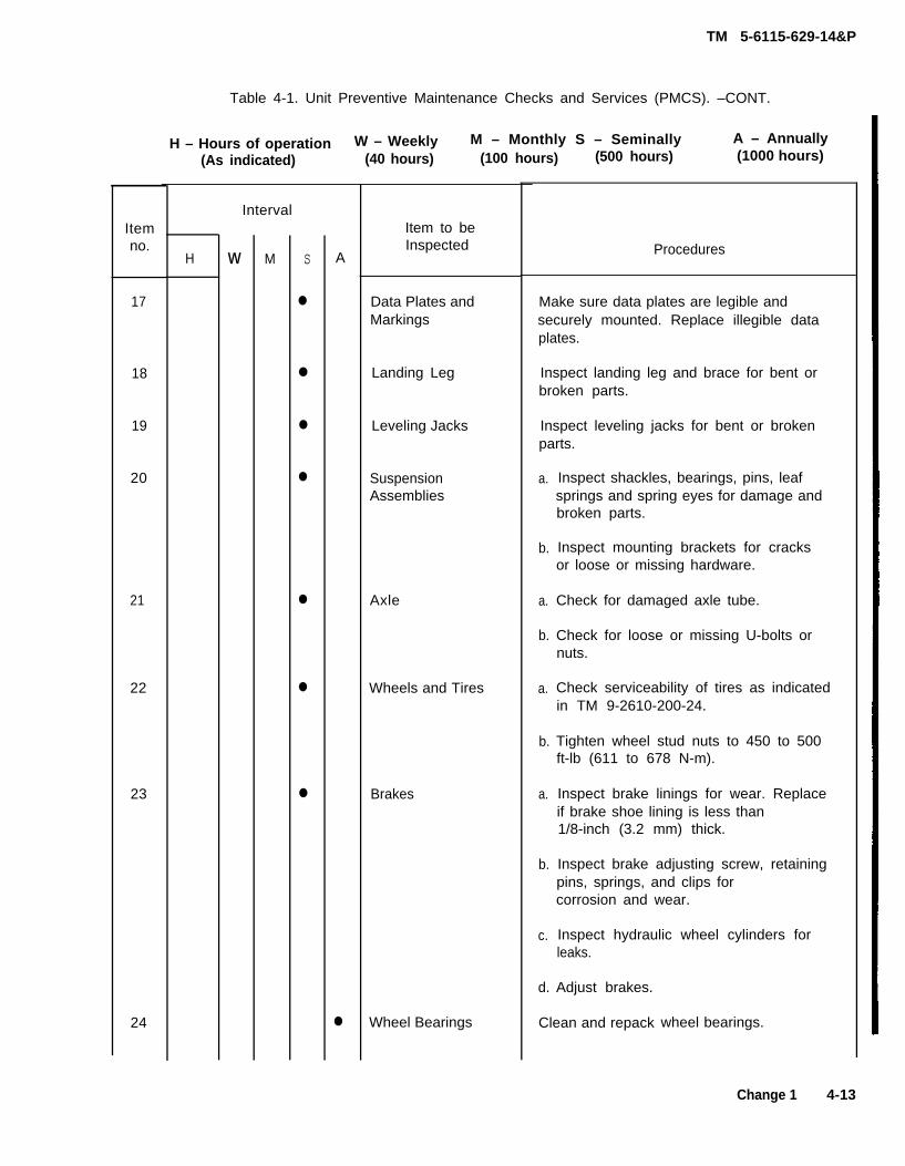
Table 4-1. Unit Preventive Maintenance Checks and Services (PMCS). –CONT.
H
Interval
w M s
●
●
●
●
●
●
●
A
●
Item to beInspected
Data Plates andMarkings
Landing Leg
Leveling Jacks
SuspensionAssemblies
Axle
Wheels and Tires
Brakes
Wheel Bearings
H – Hours of operation W – Weekly M – Monthly S – Seminally A – Annually
Make sure data plates are legible andsecurely mounted. Replace illegible dataplates.
Inspect landing leg and brace for bent orbroken parts.
Inspect leveling jacks for bent or brokenparts.
a.
b.
a.
b.
a.
b.
a.
b.
c.
d.
Inspect shackles, bearings, pins, leafsprings and spring eyes for damage andbroken parts.
Inspect mounting brackets for cracksor loose or missing hardware.
Check for damaged axle tube.
Check for loose or missing U-bolts ornuts.
Check serviceability of tires as indicatedin TM 9-2610-200-24.
Tighten wheel stud nuts to 450 to 500ft-lb (611 to 678 N-m).
Inspect brake linings for wear. Replaceif brake shoe lining is less than1/8-inch (3.2 mm) thick.
Inspect brake adjusting screw, retainingpins, springs, and clips forcorrosion and wear.
Inspect hydraulic wheel cylinders forleaks.
Adjust brakes.
Clean and repack wheel bearings.
Change 1 4-13
TM 5-6115-629-14&P
Table 4-7. Unit Preventive Maintenance Checks and Services (PMCS). –CONT.
H - Hours of operation W - Weekly M – Monthly S – Seminally A – Annually(As indicated) (40 hours) (100 hours) (500 hours) (1000 hours)
IntervalItem Item to beno.
HInspected
W M S A Procedures
25 ● Hydraulic Brake Inspect for dents, cracks, loose connectionsHoses and Fittings and leaks.
26 ● Air Hoses and Inspect for dents, cracks, loose connectionsFittings and leaks.
27 ● Brake Master Check fluid level. Fill to 1/2 inch fromtop.
28 ● Trailer Road Test Perform road test paying special attentionto items that were repaired or adjusted,in accordance with TM 9-2330-205-14&P.
Section VI. TROUBLESHOOTING
4-13. General. Troubleshooting procedures for components unique to the power plant end item aregiven in paragraph 4-14. Troubleshooting information for the individual generator sets and trailers arecontained in their respective manuals referenced below:
a. Generator Set Troubleshooting. Refer to TM 5-6115-545-12 for troubleshooting proceduresapplicable to the trailers.
b . Trailer Troubleshooting. Refer to TM 9-2330-205-14&P for troubleshooting procedures applicableto the trailers.
4-14. Power Plant Troubleshooting. Table 4-2 contains troubleshooting information for locating thecorrecting operating troubles which may develop in components unique to the power plant end item.Each malfunction is foIlowed by a list of tests or inspections which will help determine probable causeand corrective actions to take. Perform the tests/inspections and corrective actions in the order listed.This manual cannot list all malfunctions that may occur, nor all tests or inspections and correctiveactions. If a malfunction is not listed or cannot be corrected by listed corrective actions, notify yoursupervisor.
* U.S. GOVERNMENT PRINTING OFFICE: 1989-754-029/ 00409
4-14 Change 1
TM 5-6115-629-14&P
Table 4-2. Troubleshooting.
MalfunctionTest or inspection
Corrective action
1. POWER IS ABSENT AT SWITCH BOX LOAD TERMINAL(S) WHEN ONE PARTICULAR POWER UNIT IS
SELECTED.
Step 1.
Step 2.
Step 3.
Step 4.
Step 5.
Check if associated generator set circuit breaker is set to ON position.
If circuit breaker is in OFF position, reset to ON position.
Verify associated generator set output is as desired. Check generator output atload terminals.
If power is absent at generator set load terminals, troubleshootgenerator set. (Refer to TM 5-6115-545-12.)
Perform continuity check on associated power unit power cable.
If cable is defective, notify higher level of maintenance.
Perform continuity check on associated switchbox connector.
If connector is defective, notify higher level of maintenance.
Perform continuity check on associated switch.
If switch is defective, notify higher level of maintenance.
2. POWER IS ABSENT AT ONE OR MORE SWITCH BOX LOAD TERMINALS WHEN EITHER POWER UNITIS SELECTED.
Step 1. Check load terminal(s) for looseness or damage.
a. If terminal is loose, tighten.
b. If terminal is damaged, notify higher level of maintenance.
Step 2. Inside switchbox, check wires associated with inoperative terminal(s) forlooseness or broken wire terminals.
Tighten loose connection, repair or replace broken wires.
3. ONE OR MORE INDICATOR LAMPS DO NOT LIGHT WHEN POWER IS APPLIED BY POWER PLANTTHROUGH SWITCH BOX.
Step 3. Perform continuity check on indicator housing.
If indicator housing is defective, replace.
Section VII. RADIO INTERFERENCE SUPPRESSION
4-15. General Methods Used to Attain Proper Suppression. Essentially, suppression is attained byproviding a low resistance path to ground for stray currents. The methods used include shielding igni-tion and high-frequency wires, grounding the frame with bonding straps, and using filtering systems.
4-16. Radio Interference Suppression Components. All component parts of the power plant enditem, whose primary or secondary function is radio interference suppression, are on the generatorsets. Refer to TM 5-6115-545-12 for location of radio interference suppression components.
Section VIII. MAINTENANCE OF POWER PLANT TRAILERS
4-17. General. This section of the manual contains unit level maintenance procedures forcomponents of the M200A1 trailer added when the trailer is used as part of the AN/MJQ-12A powerplant. These components are not covered in the overall trailer maintenance manual. For all other unitmaintenance procedures on the trailer, refer to TM 9-2330-205-14&P.
WARNING
Before performing any maintenance that requires climbing on or under trailer,set trailer handbrakes, chock both wheels, and lower rear leveling jacks.Injury to personnel could result from trailer suddenly rolling or tipping.
4-18. Fuel Can Bracket Replacement. (See figure 4-5.) There are four fuel can brackets suppliedwith the AN/MJQ-12A. Two brackets are mounted on top of the curbside front steps on each powerunit. Replacement procedures described below are typical for all.
4-16
TM 5-6115-629-14&P
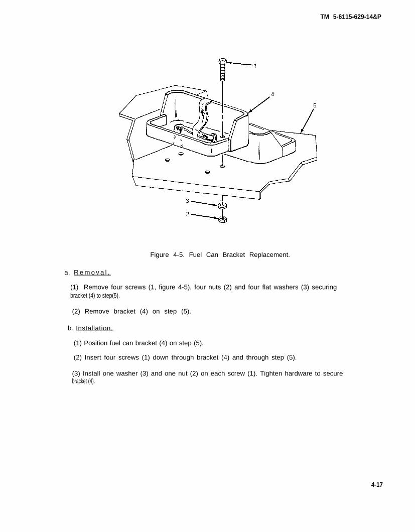
Figure 4-5. Fuel Can Bracket Replacement.
a. R e m o v a l .
(1) Remove four screws (1, figure 4-5), four nuts (2) and four flat washers (3) securingbracket (4) to step(5).
(2) Remove bracket (4) on step (5).
b. Installation.
(1) Position fuel can bracket (4) on step (5).
(2) Insert four screws (1) down through bracket (4) and through step (5).
(3) Install one washer (3) and one nut (2) on each screw (1). Tighten hardware to secure bracket (4).
4-17
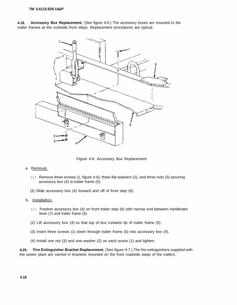
4-19.
TM 5-6115-629-14&P
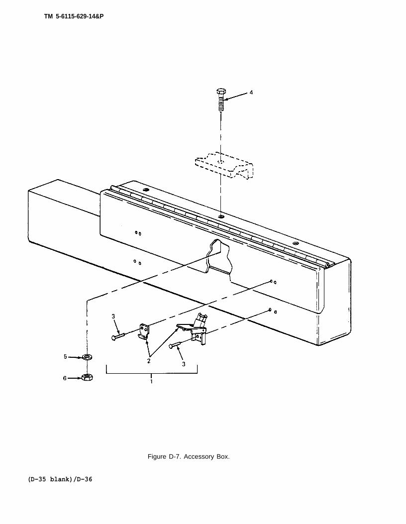
Accessory Box Replacement. (See figure 4-6.) The accessory boxes are mounted to thetrailer frames at the curbside front steps. Replacement procedures are typical.
Figure 4-6. Accessory Box Replacement.
a. Removal.
(1) Remove three screws (1, figure 4-6), three flat washers (2), and three nuts (3) securingaccessory box (4) to trailer frame (5).
(2) Slide accessory box (4) forward and off of front step (6).
b. Installation.
(1) Position accessory box (4) on front trailer step (6) with narrow end between handbrakelever (7) and trailer frame (5).
(2) Lift accessory box (4) so that top of box contacts lip of trailer frame (5).
(3) Insert three screws (1) down through trailer frame (5) into accessory box (4).
(4) Install one nut (3) and one washer (2) on each screw (1) and tighten.
4.20. Fire Extinguisher Bracket Replacement. (See figure 4-7.) The fire extinguishers supplied withthe power plant are carried in brackets mounted on the front roadside steps of the trailers.
4-18
TM 5-6115-629-14&P
Figure 4-7. Fire Extinguisher Bracket Replacement.
a. Removal.
(1) Remove four screws (1, figure 4-7), four flat washers (2), and four nuts (3) securingbracket (4) to step (5).
(2) Remove bracket (4) from step (5).
b. Installation.
(1) Position fire extinguisher bracket (4) on step (5).
(2) Insert four screws (1) down through bracket (4) and through step (5).
(3) Install one washer (2) and one nut (3) on each screw (1). Tighten hardware to securebracket (4).
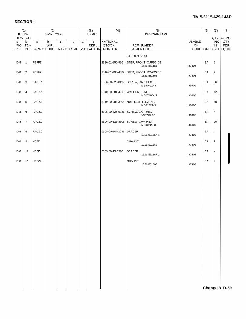
4-21. Front Steps Replacement. (See figure 4-8.) The roadside and curbside front steps on bothtrailers are symmetrical, and replacement procedures are the same except where noted in the stepsbelow.
a. Removal.
NOTE
When removing roadside front step, omit steps (1) and (2).
(1) Remove fuel can brackets (paragraph 4-18, a).
(2) Remove accessory box (paragraph 4-19, a).
(3) Remove cotter pin (1, figure 4-8) and clevis pin (2) securing handbrake cable (3) tohandbrake lever mechanism (4).
4-19
(4) Remove two screws (5), two flat washers (6) and two nuts (7) securing handbrake bracket(8) to trailer frame (9).
TM 5-6115-629-14&P
Figure 4-8. Front Steps Replacement.
4-20
(6)
(7)
(8)
(9)
TM 5-6115-629-14&P
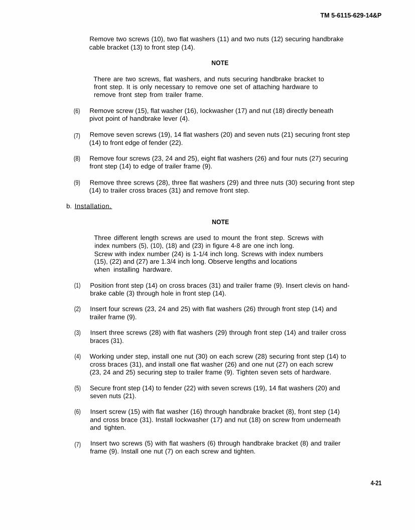
Remove two screws (10), two flat washers (11) and two nuts (12) securing handbrakecable bracket (13) to front step (14).
NOTE
There are two screws, flat washers, and nuts securing handbrake bracket tofront step. It is only necessary to remove one set of attaching hardware toremove front step from trailer frame.
Remove screw (15), flat washer (16), Iockwasher (17) and nut (18) directly beneathpivot point of handbrake lever (4).
Remove seven screws (19), 14 flat washers (20) and seven nuts (21) securing front step(14) to front edge of fender (22).
Remove four screws (23, 24 and 25), eight flat washers (26) and four nuts (27) securingfront step (14) to edge of trailer frame (9).
Remove three screws (28), three flat washers (29) and three nuts (30) securing front step(14) to trailer cross braces (31) and remove front step.
b. Installation.
(1)
(2)
(3)
(4)
(5)
(6)
(7)
NOTE
Three different length screws are used to mount the front step. Screws withindex numbers (5), (10), (18) and (23) in figure 4-8 are one inch long.Screw with index number (24) is 1-1/4 inch long. Screws with index numbers(15), (22) and (27) are 1.3/4 inch long. Observe lengths and locationswhen installing hardware.
Position front step (14) on cross braces (31) and trailer frame (9). Insert clevis on hand-brake cable (3) through hole in front step (14).
Insert four screws (23, 24 and 25) with flat washers (26) through front step (14) andtrailer frame (9).
Insert three screws (28) with flat washers (29) through front step (14) and trailer crossbraces (31).
Working under step, install one nut (30) on each screw (28) securing front step (14) tocross braces (31), and install one flat washer (26) and one nut (27) on each screw(23, 24 and 25) securing step to trailer frame (9). Tighten seven sets of hardware.
Secure front step (14) to fender (22) with seven screws (19), 14 flat washers (20) andseven nuts (21).
Insert screw (15) with flat washer (16) through handbrake bracket (8), front step (14)and cross brace (31). Install Iockwasher (17) and nut (18) on screw from underneathand tighten.
Insert two screws (5) with flat washers (6) through handbrake bracket (8) and trailerframe (9). Install one nut (7) on each screw and tighten.
4-21
TM 5-6115-629-14&P
(8) Insert two screws (10) through front step (14) and handbrake cable bracket (13). Installone flat washer (11) and one nut (12) on each screw and tighten.
(9) Position clevis on handbrake cable (3) on handbrake lever mechanism (4). Insert clevispin (2) and secure with cotter pin (1).
NOTE
When installing roadside front step, omit steps (10) and (11).
(10) Install accessory box (paragraph 4-19, b).
(11) Install fuel can brackets (paragraph 4-18, b).
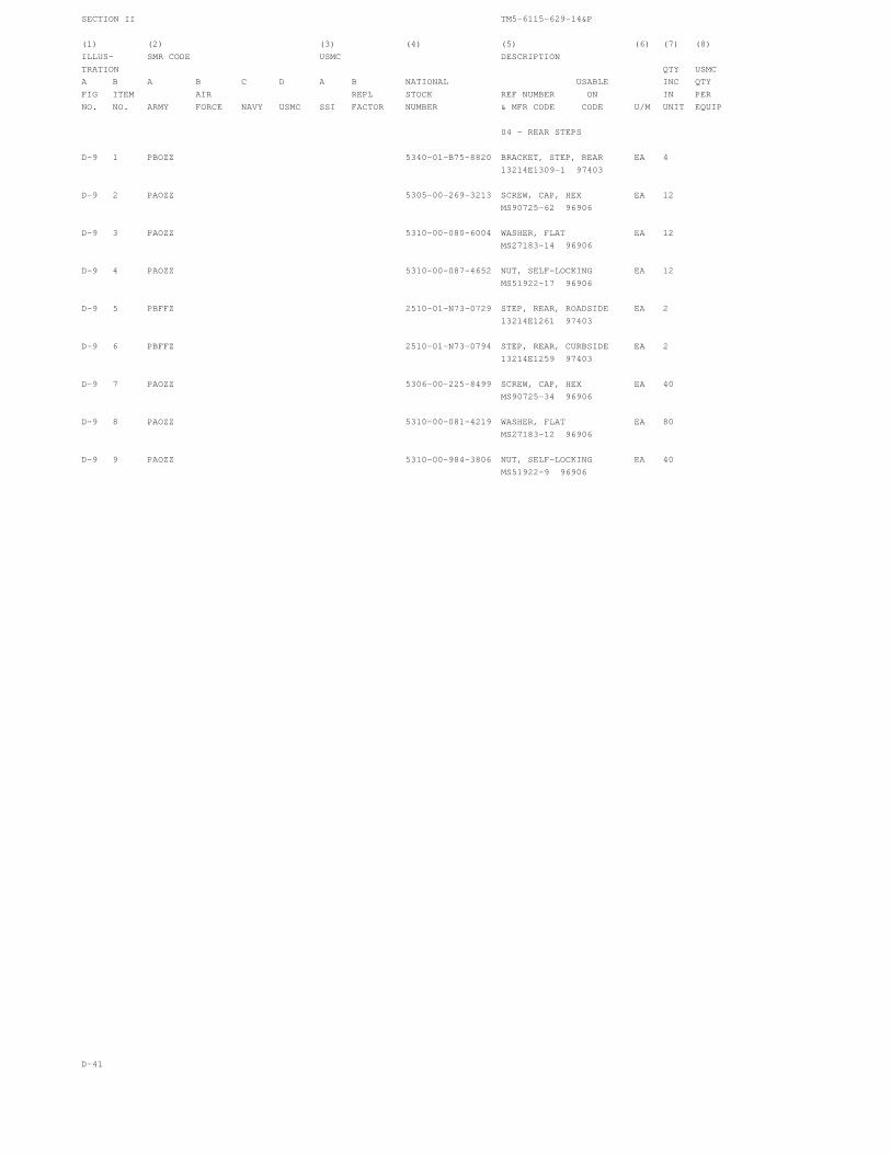
4-22. Rear Steps Replacement. (See figure 4-9.) The roadside and curbside rear steps on bothtrailers are symmetrical, and replacement procedures are the same for all.
a. Removal.
(1) Remove two screws (1, figure 4-9), two flat washers (2) and two nuts (3) securing rearstep bracket (4) and platform anchor (5) to trailer frame (6) under taillight (7).
(2) Remove two screws (8), four flat washers (9) and two nuts (10) securing rear step (11) totrailer frame (6).
(3) Remove five screws (12), ten flat washers (13) and five nuts (14) securing rear step (11)to fender (15). Remove rear step from trailer.
Figure 4-9. Rear Steps Replacement.
4-22
TM 5-6115-629-14&P
b. Installation.
(1) Position rear step (11) on trailer frame (6).
(2) Secure rear step (11) to trailer frame (6) with two screws (8), four flat washers (9) andtwo nuts (10).
(3) Secure rear step (11) to fender (15) with five screws (12), ten flat washers (13) and fivenuts (14).
(4) Aline two mounting holes in rear step bracket (4) with holes in trailer frame (6) undertaillight (7) and insert two screws (1).
(5) Slide S-hook at chain end of platform anchor (5) onto threaded end of lower screw (1)inside trailer frame (6).
(6) Install one flat washer (2) and one nut (3) on each screw (1) and tighten.
4-23. Fender Replacement. (See figure 4-10.) The fenders on the trailer assemblies aresymmetrical, and replacement procedures are the same for all.
a. Removal.
(1)
(2)
(3)
(4)
(5)
(6)
Remove five screws (1, figure 4-10), ten flat washers (2) and five nuts (3) securingfender (4) to trailer frame (5).
WARNING
There are five sets of hardware securing fender to rear step and seven sets ofhardware securing fender to front step. This hardware should be removed insequence from trailer frame outward. In this way, last two screws on front andrear lower fender edge will support fender until you are out from underneath.
Remove six screws (6), 12 flat washers (7) and six nuts (8) securing fender (4) to frontstep (9).
Remove fours screws (10), eight flat washers (11) and four nuts (12) securing fender (4)to rear step (13).
WARNING
Support fender while removing remaining two screws. When screws areremoved, fender will drop.
Remove one screw (6), two flat washers (7) and one nut (8) securing fender (4) to frontstep (9).
Remove one screw (10), two flat washers (11) and one nut (12) securing fender (4) torear step (13).
Remove fender (4).
4-23
TM 5-6115-629-14&P
Figure 4-10. Fender Replacement.
4-24
b. Installation.
TM 5-6115-629-14&P
(1)
(2)
(3)
(4)
(5)
(6)
(7)
Position fender (4) on trailer.
Insert one screw (10) with flat washer (11) through lower outside edge of fender (4) intorear step (13), and insert one screw (6) with flat washer (7) through lower outside edge offender (4) into front step (9).
Install one washer (11) and one nut (12) on screw (10), and one washer (7) and onenut (8) on screw (6). Tighten hardware.
Insert five screws (1) with flat washers (2) down through fender (4) into trailer frame (5).
Working under fender, install one flat washer (2) and one nut (3) on each screw (1) andtighten.
Insert six screws (6) with flat washers (7) through fender (4) into front step (9). Installone washer (7) and one nut (8) on each screw (6) and tighten.
Insert four screws (10) with flat washers (11) through fender (4) into rear step (13).Install one washer (11) and one nut (12) on each screw (10) and tighten.
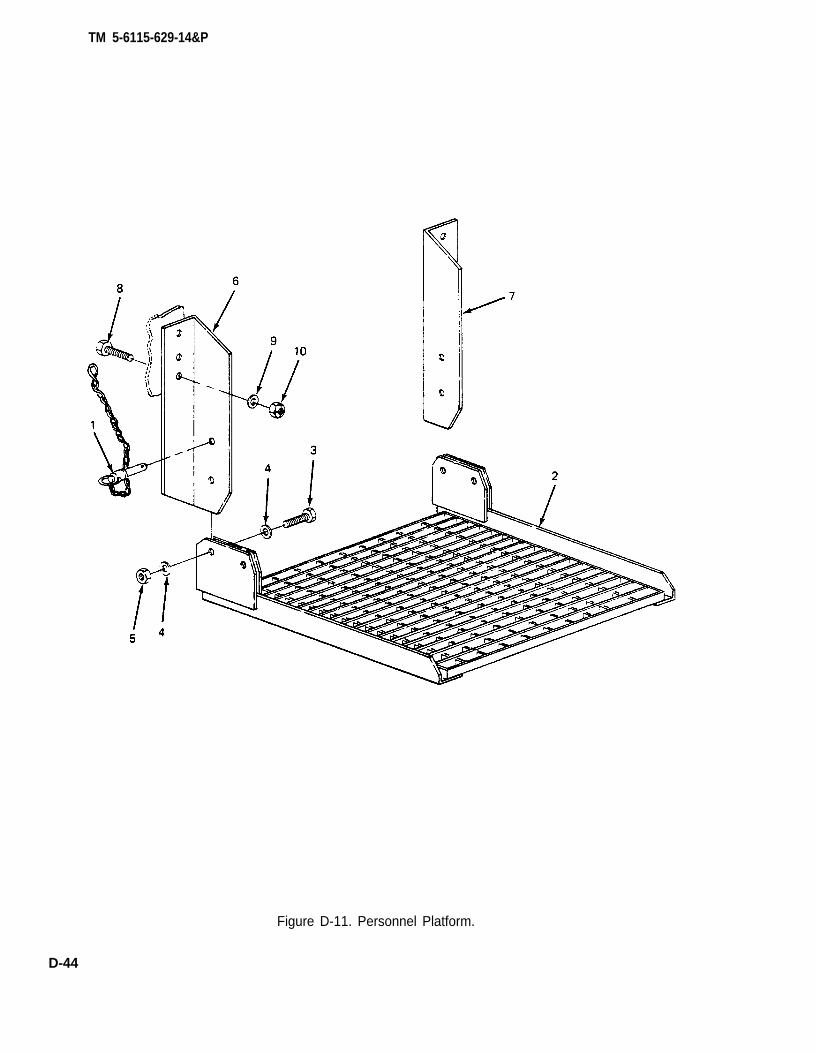
4-24. Personnel Platform Replacement. (See figure 4-11). This platform is mounted on the rear ofeach trailer to facilitate access to generator set controls and indicators.
a. Removal.
(1) Remove two screws (1, figure 4-11), four flat washers (2) and two nuts (3) securingplatform (4) to mounting brackets (5).
WARNING
Support platform while removing anchors. When anchors are removed,platform will drop.
(2) Remove two platform anchors (6) by pushing in on button on head of pin while pulling pinout of mounting hole.
NOTE
Mounting brackets are fastened with lock nuts. Removal may damage lockingcapability when reinstalled. Do not remove mounting brackets unless they aredamaged.
4-25
(3) Remove three screws (7), six flat washers (8) and three nuts (9) from each mountingbracket (5) and take mounting brackets off of trailer frame (10).
TM 5-6115-629-14&P
Figure 4-11. Personnel Platform Replacement.
b. Installation.
NOTE
If mounting brackets have not been removed, omit step (1).
(1) Position each mounting bracket (5) on trailer frame (10). Insert three screws (7) with flatwashers (8) through frame into each bracket. Install one washer (8) and one nut (9) oneach screw and tighten.
(2) Holding platform (4) in vertical position, position platform on mounting brackets (5) sothat holes in platform line up with holes in brackets and install platform anchors (6) inupper mounting hole on each side of platform.
(3) Secure platform (4) to brackets (5) with two screws (1), four flat washers (2) and twonuts (3).
4 - 2 6
TM 5-6115-629-14&P
4-25. Holddown Strap Replacement. (See figure 4-12.) Three holddown straps are provided on theroadside fender of each power unit. These straps are used to secure the power cables when the powerplant is in transit. Replacement procedure is typical.
a. Removal.
(1) Remove two screws (1, figure 4-12), two washers (2), and two nuts (3) securing foot-mans loop (4) to trailer (5).
(2) Slide holddown strap (6) off footmans loop (4).
(2) Position footmans loop (4) on trailer body (5) and secure with two screws (1), twowashers (2), and two nuts (3).
Figure 4-12. Holddown Strap Replacement.
SECTION IX. MAINTENANCE OF ELECTRICAL SYSTEM
4-26. General. This section of the manual contains unit level maintenance procedures for electricalcomponents that are unique to the AN/MJQ-12A power plant. Specifically, this includes the switch boxand the power cables.
4-27 Cable Testing. A continuity test is used to detect opens or shorts in the power plant powercables. The two cables differ from each other only in length. The following test procedure is typical forboth.
a. Set multimeter controls to prepare unit for continuity testing.
NOTE
The contacts in the connector end of cable are labeled A, B, C, N, and G1thru G4. The individual colored wires at the other end of cable are labeled L0,L1, L2, L3, and GEN GND.
b. Touch one probe to contact A in connector and touch remaining probe to black wire labeledL1. Multimeter must indicate continuity. If it does not, cable is open.
4-27
c.
d.
TM 5-6115-629-14&P
With first probe still in contact A, touch remaining probe to wires labeled L2, L3, L0, andGEN GND. Multimeter must not indicate continuity. If it does, cable is shorted.
Refer to figure 4-13, and repeat steps b. and c. at connector contacts B, C, and N. In eachcase, continuity must exist between corresponding points and only between correspondingpoints.
Figure 4-13. Power Cable Wiring Diagram.
e. Connect one multimeter probe to GEN GND lug on cable and touch remaining probe to G1,G2, G3, and G4. Continuity must be indicated on each contact.
f. If continuity test detects any opens or shorts in cable, refer cable to higher level ofmaintenance.
4-28. Switch Box Testing. The power plant switch box assembly is tested by performing a series ofcontinuity checks on the component parts and internal wiring.
NOTE
All internal switch box wiring is labeled for identification with referencedesignations of its points of connection. If labeling has been removed, or isillegible, tag wires for identification before removing them.
a. Switch Testing. The switch box contains two three-pole, single-throw switches. Testingprocedures are typical for both.
WARNING
To avoid risk of injury or death by electrocution, do not remove switch boxaccess cover while either power unit is still connected to switch box.
(1) Remove 14 screws, 14 Iockwashers, and 14 flat washers securing access cover to switchbox and remove cover.
(2) Set multimeter controls to prepare unit for continuity testing.
(3) Set switch being tested to ON position.
4-28
TM 5-6115-629-14&P
NOTE
Observe that the switch terminals are arranged in two rows of three terminalseach. Each terminal is paired with the one directly above or below it. There isone pair of terminals for each pole of the switch.
(4) Select any pair of terminals associated with same pole of switch. Touch one multimeter testprobe to each terminal. Multimeter must indicate continuity.
(5) Repeat step (4) on both remaining poles of switch.
(6) If multimeter does not indicate continuity across all three poles of switch, switch isdefective. Refer switch to higher level of maintenance.
b. Connector Testing. The switch box has four male cable connectors. The larger connectors, J1and J2, are the power input connectors. Together with their associated wiring, they comprise theswitch box cable assemblies. This procedure tests the entire cable assembly. The connectors willhave either four or eight pins depending upon whether the power plant is equipped with a 4-wire or 5-wire switch box. The procedure is as follows:
WARNING
To avoid risk of injury or death by electrocution, do not remove switch boxaccess cover while either power unit is still connected to switch box.
NOTE
(1)
(2)
(3)
(4)
(5)
(6)
(7)
Observe that pins on power input connectors are labeled A, B, C, and N. On5-wire switch boxes, the four additional pins are labeled G1, G2, G3, and G4.
Remove 14 screws, 14 Iockwashers, and 14 flat washers securing access cover to switchbox and remove cover.
Set multimeter controls to prepare unit for continuity testing.
Touch one multimeter test probe to pin A in connector being tested and touch remainingprobe to terminal A1 on associated switch. Multimeter must indicate continuity. If it doesnot, there is an open in connector or associated wire.
With first probe still in contact with pin A, touch remaining probe to all other pins inconnector. Multimeter must not indicate continuity. If it does, connector is shorted.
Repeat steps (3) and (4) for pins B, C, and N. Multimeter must indicate continuity onlybetween these pins and switch terminals B1, C1, and TB1 L0 terminal, respectively.
NOTE
Step (6) is applicable only to 5-wire switch box.
Touch one multimeter test probe to terminal 1 on TB2. Touch remaining probe to pins G1,G2, G3, and G4, in turn. Multimeter must indicate continuity on each pin.
If continuity test detects any opens or shorts, connector cable assembly is defective.
4-29
TM 5-6115-629-14&P
c. Wiring Test. (Refer to wiring diagrams, Figure 4-14 and 4-15.) The internal switch box wiringis tested by performing a continuity check(s) on suspect wires or connections.
WARNING
(1)
(2)
(3)
(4)
To avoid risk of injury or death by electrocution, do not remove switch boxaccess cover while either power unit is still connected to switch box.
NOTE
All internal switch box wiring is labeled for identification with referencedesignations of its points of connection. If labeling has been removed, or isillegible, tag wires for identification before removing them.
Remove 14 screws, 14 Iockwashers, and 14 flat washers securing access cover to switchbox and remove cover.
Before testing wires, make sure there are no loose connections or broken terminals.Tighten any loose connections and refer broken terminals to higher level of maintenance,
Set multimeter controls to prepare unit for continuity testing.
Refer to applicable wiring diagram in Figure 4-14 or 4-15, and test continuity of suspectwires between origin and destination specified in diagram.
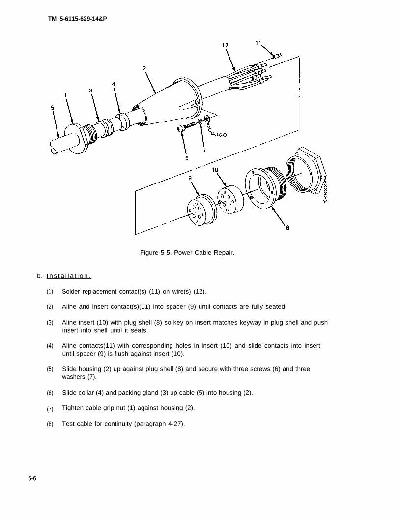
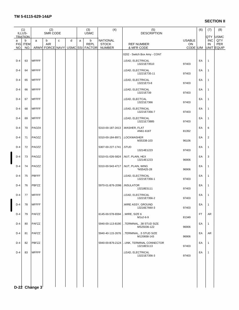
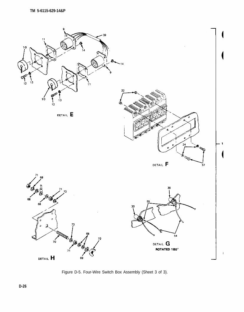
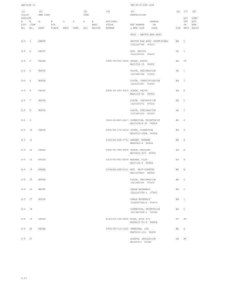
4-29. Switch Box Repair. The power plant switch box assembly is repaired by replacing defectivecomponents. Components authorized for replacement at unit level of maintenance include connectorcable assemblies, load terminals, and individual wires.
NOTE
All internal switch box wiring is labeled for identification with referencedesignations of its points of connection. If labeling has been removed, or isillegible, tag wires for identification before removing them.
a. Connector Replacernent. (See figure 4-16.) A damaged or defective connector is replaced byreplacing the entire connector cable assembly,
WARNING
To avoid risk of injury or death by electrocution, do not remove switch boxaccess cover while either power unit is still connected to switch box.
(1) Removal.
(a)
(b)
(c)
4-30
Remove 14 screws (1, figure 4-16), 14 Iockwashers (2), and 14 flat washers (3)securing access cover (4) to switch box (5) and remove cover.
Disconnect connector cable assembly wire (6) from insulator TB2 (7) by removing nut(8), Iockwasher (9), flat washer (10), two electrical leads (11), ground wire (12)and, if necessary, flat washer (13) from terminal stud numer one (14).
Disconnect each of three connector cable assembly wires (15) from terminals of asso-ciated switch (16) by removing one nut (17) and one Iockwasher (18).
(e) Remove four screws (25) and four nuts (26) securing connector flange (27) to switchbox (5). Carefully remove connector and associated wiring from switch box.
(2) Installation.
(a)
(b)
(c)
(d)
(e)
(f)
Feed connector cable assembly wires through mounting hole in switch box (5).
Position connector body in mounting hole and secure with four screws (25) and four nuts(26). Use screw in lower right-hand corner of flange (27) to secure connector capretaining chain (28).
NOTE
When reconnecting wires, refer to figure 4-14 or 4-15, as applicable.
Connect each of three connector cable assembly wires (15) to terminals of associatedswitch (16) with one nut (17) and one Iockwasher (18).
Connect cable assembly wire (6) to terminal stud number one (14) of insulator TB2 withnut (8), Iockwasher (9), flat washer (10) and, if necessary, flat washer (13). Makesure electrical leads (11) and ground wire (12) are reinstalled and positioned as shownin figure 4-16.
In five-wire switch boxes, connect cable assembly ground wire (19) to load terminal L0(20) with flat washer (24), Iockwasher (23) and nut (22).
Position access cover (4) on switch box (5) and secure with 14 screws (1), 14 lock-washers (2), and 14 flat washers. (3).
b. Load Terminal Replacement. (See figure 4-17.) The switch box load terminals provide elec-tromechanical connection points between the system or equipment being powered and the powerplant. In addition to the four output terminals, the 5-wire switch box utilizes a fifth load terminal as ACGROUND.
WARNING
To avoid risk of injury or death by electrocution, do not remove switch boxaccess cover while either power unit is still connected to switch box.
(1) Removal.
(a) Remove 14 screws (1, figure 4-17), 14 Iockwashers (2), and 14 flat washers (3)securing access cover (4) to switch box (5) and remove cover.
(b) Remove one nut (6) one Iockwasher (7), one flat washer (8), and remove associatedwires (9) from load terminal (10).
(12), and one flat washer (13) and remove load(c) Remove one nut (11), one Iockwasherterminal (10) from terminal board (14).
4-33
TM 5-6115-629-14&P
Figure 4-16. Connector Replacement.
Figure 4-17. Load Terminal Replacement.
4 - 3 4
TM 5-6115-629-14&P
(2) Installation.
(a) Install load terminal (10) in terminal board (14) and secure with flat washer (13),Iockwasher (12) and nut (11).
(b) Install associated wires (9) on load terminal (10) and secure with flat washer (8),Iockwasher (7), and nut (6).
(c) Position access cover (4) on switch box (5) and secure with 14 screws (1),14 Iockwashers (2), and 14 flat washers (3).
4-35/(4-36 blank)
TM 5-6115-629-14&P
CHAPTER 5
INTERMEDIATE (FIELD) DIRECT SUPPORT ANDGENERAL SUPPORT MAINTENANCE INSTRUCTIONS
Section I. INTRODUCTION
5-1. General. This chapter contains Intermediate Direct Support and General Support level mainte-nance procedures for components of the M200A1 trailer added when the trailer is used as part of theAN/MJQ-12A power plant. These components are not covered in the overall trailer maintenancemanual. For all other intermediate direct and general support maintenance procedures on the trailer,refer to TM 9-2330-205-14&P. For intermediate direct and general support maintenance procedureson the generator sets, refer to TM 5-6115-545-34.
Before performing any maintenance that requires climbing on or under trailer,set trailer handbrakes, chock wheels, and lower rear leveling jacks. Injury topersonnel could result from trailer suddenly rolling or tipping.
Section Il. MAINTENANCE OF POWER PLANT TRAILERS
5-2. Step and Fender Repair. Repair of the front and rear steps and the fenders is limited tostraightening, welding and repainting. If required, repaint in accordance with MIL-T-704, Type F,Color Green, No. 383 of MIL-C-46168.
5-3. Accessory Box Repair. (See figure 5-1.) The accessory boxes are repaired by replacing thelatch and strike assemblies. The boxes themselves may be straightened, welded and repainted. Ifrequired, repaint in accordance with MIL-T-704, Type F, Color Green, No. 383 of MIL-C-46168.Replace latch and strike assemblies as follows:
a.
b.
c.
Grind off or drill out solid rivets (1, figure 5-1) securing latch and strike assembly (2) toaccessory box (3).
Position new latch and strike assembly (2) on accessory box (3) and secure with solidrivets (1).
Touch up with paint as required.
Figure 5-1. Accessory Box Repair.
5-1
TM 5-6115-629-14&P
5-4. Marking. (See figure 5-2.) The power unit four-digit registration number, preceded by theprefix “VA” and the words “U.S. ARMY”, is marked in three places on each power unit trailer. Markingis done in accordance with MIL-STD-642. On the fender, over each wheel, “T.P. 35 PSI” is marked in1.00 ± .12 inch high characters in accordance with MIL-STD-130. Figure 5-2 shows the approxi-mate location of markings on one power unit of the power plant. Markings are typical of both powerunits. If required, touch-up painting of the base color shall be done in accordance with MIL-T-704,Type F, Color Green, No. 383 of MIL-C-46168.
5-5. Generator Set Replacement. (See figures 5-3 and 5-4.)
Figure 5-2. Power Plant Markings.
Section Ill. GENERATOR SET
a. Removal.
(1) Disconnect ground wire (1, figure 5-3) from generator set (2) to GROUND TERMINAL stud(3) on trailer.
NOTE
Two center mounting screws on each side can be reached through cutouts intrailer frame under each fender. Observe that two mounting screws (5) at frontcorners of generator set are shorter than remaining six mounting screws (4).The beveled washers (6) may have been welded in place.
5-2
TM 5-6115-629-14&P
Figure 5-3. Detaching Generator Set from Trailer.
(2) Remove six screws (4), two screws (5), eight beveled washers (6), eight flat washers(7) and eight nuts (8) securing generator set (2) to trailer.
When lifting generator set, use lifting equipment with a minimum lifting capa-city of 5000 lb. Do not stand under generator while it is being lifted. Do notpermit generator set to swing. Failure to observe these precautions can causeinjury to personnel or damage to equipment.
(3) Attach lifting equipment with a minimum lifting capacity of 5000 lb (1, figure 5-4) to bothlifting eyes (2) on top edges of generator set (3). Insert a rope (4) through each of fourtiedown rings (5) on generator set.
(4) With one person at each rope to steady and guide generator set (3), lift generator set off oftrailer.
5-3
TM 5-6115-629-14&P
5-4
Figure 5-4. Lifting Generator Set.
b. Installation.
When lifting generator set, use lifting equipment with a minimum lifting capa-city of 5000 lb. Do not stand under generator while it is being lifted. Do notpermit generator set to swing. Failure to observe these precautions can causeinjury to personnel or damage to equipment.
(1) Attach lifting equipment with a minimum lifting capacity of 5000 lb (1, figure 5-4) to liftingeyes (2) on top edges of generator set (3). Insert a rope (4) through each of four tiedownrings (5) on generator set.
(2) With one person at each rope to steady and guide generator set (3), lift generator set andcarefully lower it onto trailer.
NOTE
Two center mounting screws on each side can be reached through cutouts intrailer frame under each fender. The two shorter mounting screws (5, figure5-3) are installed at the front corner positions.
(3) Insert six screws (4, figure 5-3) and two screws (5) with beveled washers (6) downthrough generator set skids into trailer.
(4) Working under trailer install one Iockwasher (7) and one nut (8) on each screw (4)and (5).
TM 5-6115-629-14&P
(5) Position beveled washers (6) so that screw heads are parallel to tops of washers. Whileholding beveled washers in position, tighten hardware.
(6) Connect generator set ground wire (1) to trailer GROUND TERMINAL stud (3).
Section IV. MAINTENANCE OF ELECTRICAL SYSTEM
5-6. Power Cable Repair. The power plant cables are repaired by resoldering or replacing loose ordamaged contacts inside the connector. A soldered contact can be unsoldered and a new one in-stalled in its place. If, however, the damaged contact is crimped onto the wire, or if the wire is brok-en, the contact must be cut off. When one wire in the cable has been cut or broken, all wires must becut to the same length and new contacts soldered on each. Refer to TB SIG 222 (TO 31-3-64) andTM 55-1500-323-25 (TO 1-1A -14).
a. Removal.
NOTE
Cable grip nut is left hand threaded. Turn clockwise to loosen.
(2) Slide cable grip nut (1), packing gland (3) and collar (4) up cable (5) away fromhousing (2).
(3) Remove three screws (6) and three washers (7) and separate housing (2) from plugshell (8).
(4) Remove spacer (9) and insert (10) from plug shell (8).
(5) Remove contact(s) (11) being repaired or replaced from spacer (9) and insert (10).Unsolder contact(s) (11) from wire(s) (12).
NOTE
If contact is crimped onto wire, or if wire is broken, do steps (6) through (8).
(6) Cut contacts (11) off wires (12).
(7) Strip back cable jacket to expose more of individual wires.
(8) Cut wires to equal length. Strip and tin wires in accordance with procedures given intechnical manuals referenced above.
5-5
TM 5-6115-629-14&P
b. I n s t a l l a t i o n .
(1)
(2)
(3)
(4)
(5)
(6)
(7)
(8)
5-6
Figure 5-5. Power Cable Repair.
Solder replacement contact(s) (11) on wire(s) (12).
Aline and insert contact(s)(11) into spacer (9) until contacts are fully seated.
Aline insert (10) with plug shell (8) so key on insert matches keyway in plug shell and pushinsert into shell until it seats.
Aline contacts(11) with corresponding holes in insert (10) and slide contacts into insertuntil spacer (9) is flush against insert (10).
Slide housing (2) up against plug shell (8) and secure with three screws (6) and threewashers (7).
Slide collar (4) and packing gland (3) up cable (5) into housing (2).
Tighten cable grip nut (1) against housing (2).
Test cable for continuity (paragraph 4-27).
TM 5-6115-629-14&P
5-7. Switch Box Repair. The power plant switch box assembly is repaired by replacing defectivecomponents or by repairing individual wires within the switch box. Replacement of the switches isauthorized only at the Intermediate Direct Support and General Support levels of maintenance.
NOTE
All internal switch box wiring is labeled for identification with reference desig-nations of its points of connection. If labeling has been removed, or is illegi-ble, tag wires for identification before removing them.
a. Switch Replacement. (See figure 5-6.)
(1) Removal.
WARNING
To avoid risk of injury or death by electrocution, do not remove switch boxaccess cover while either power unit is still connected to swtich box.
(a) Remove 14 screws (1 figure 5-6), 14 Iockwashers (2), and 14 flat washers (3) secur-ing access cover (4) to switch box (5) and remove cover.
(b) Remove six nuts (6) and six Iockwashers (7) securing wires (8) to switch (9) and slidewire terminals off threaded posts on switch.
(c) Remove four screws (10), four flat washers (11) and four nutsto switch box (5) and remove switch.
12) securing switch (9)
5-7
Figure 5-6. Switch Replacement.
TM 5-6115-629-14&P
(2) Installation.
(a) Position switch (9) in switch box (5), making certain it is right side up, and secure withfour screws (10), four washers (11), and four nuts (12).
(b) Install six wires (8) on switch (9) and secure each with one nut (6) and oneIockwasher (7).
(c) Position access cover (4) on switch box (5) and secure with 14 screws (1), 14 lock-washers (2), and 14 flat washers (3).
b. Wiring Repair. The switch box wiring is repaired by tightening or replacing loose or damagedterminals. The repair parts and special tools list in this manual lists part numbers for the terminals.The replacement terminals are soldered onto the wires in accordance with procedures given in TB SIG222 (TO 31-3-64) and TM 55-1500-323-25 (TO 1-1A-14).
5-8
TM 5-6115-629-14&P
CHAPTER 6
TEST AND INSPECTION AFTER REPAIR
Section I. GENERAL REQUIREMENTS
6-1. General Requirements. The activity performing the repair is responsible for the performance ofall applicable tests and inspections specified in the technical manuals referenced below. Activitiesperforming maintenance on any component of the power plant must perform those tests and inspec-tions required by the applicable component or system repair instruction.
Section Il. INSPECTION
6-2. Generator Set Inspections. Refer to TM 5-6115-545-12 and –34 for inspections requiredfollowing repair of the generator sets.
6-3. Trailer Inspections. Refer to TM 9-2330-205-14&P for inspections required following repair ofthe trailers.
Section Ill. OPERATIONAL TESTS
6-4. Generator Set Operational Tests. Refer to TM 5-6115-545-12 and –34 for operational testsrequired to verify satisfactory performance of the generator sets.
6-5. Trailer Operational Tests. Refer to TM 9-2330-205-14&P for operational tests required to verifysatisfactory performance of the trailers.
6-1/(6-2 blank)
TM 5-6115-629-14&P
APPENDIX A
REFERENCES
A-1. Scope. This appendix lists all pamphlets, forms, technical manuals, specifications andmiscellaneous publications referenced in this manual.
COMPONENTS OF END ITEM LIST AND BASIC ISSUE ITEMS LISTS
Section I. INTRODUCTION
B-1. Scope. This appendix lists components of end item and basic issue items for the power plant tohelp you inventory items required for safe and efficient operation.
B-2. General. The Components of End Item and Basic Issue Items Lists are divided into the followingsections:
a. Section ll. Components of End Item. This listing is for informational purposes only, and is notauthority to requisition replacements. These items are part of the end item, but are removed and sep-arately packaged for transportation or shipment. As part of the end item, these items must be with theend item whenever it is issued or transferred between property accounts. Illustrations are furnished toassist you in identifying the items.
b. Section III. Basic Issue Items. These are the minimum essential items required to place thepower plant in operation, to operate it, and to perform emergency repairs. Although shipped sep-arately packaged, Bll must be with the power plant during operation and whenever it is transferred be-tween property accounts. The illustrations will assist you with hard-to-identify items. This manual isyour authority to request/requisition replacement Bll, based on TOE/MTOE authorization of the enditem.
B-3. Explanation of Columns. The following provides an explanation of columns found in the tabularlistings:
a. Column (1), Illustration Number (Illus No.). This column indicates the number assigned tothe item.
b. Column (2), National Stock Number. Indicates the National stock number assigned to theitem.
c. Column (3), Description. Indicates the federal item name and, if required, a minimumdescription to identify and locate the item. The last line for each item indicates the FSCM (inparentheses) followed by the part number.
If item needed differed for different models of this equipment, the model would be shown under the“Usable on Code” heading in this column. The Usable On Code is not applicable for this equipment.
d. Column (4), Unit of Measure (U/M) Indicates the measure used in performing the actualoperational/maintenance function. This measure is expressed by a two-character alphabeticalabbreviation (eg, ea, in, pr).
e. Column (5), Quantity Required (Qty Req’d). Indicates the quantity of the item authorized to beused with/on the equipment.
B-1
TM 5-6115-629-14&P
Section Il. COMPONENTS OF END ITEM
(1)Illusno.
1
2
3
4
5
Figure B-1. Components of End Items
(2)National
stock number
5120-00-243-2957
5975-00-878-3791
5120-01-013-1676
(3)Description Usable
FSCM and part number on code
Hammer, Hand, Engineers 8 lb.(3.6 kg) (81348) GGG-H-86
Rod, Ground, Driven, Sectional,9 ft (2.7 m) (81348) MIL-R-11461
Hammer, Slide (97403) 13226E7741
Switch Box (97403) 13226E6296
Switch Box (97403) 13221E7360
Cable Assembly (97403) 13218E5110
Cable Assembly (97403) 13226E7626-1and
Cable Assembly (97403) 13226E7626-2
(4)
U/M
EA
EA
EA
EA
EA
EA
EA
EA
(5)Qty’dreq’d
2
4
2
1
1
2
1
1
B-2
TM 5-6115-629-14&P
(1)Illusno.
1
2
Section Ill. BASIC ISSUE ITEMS
(2)National
stock number
4210-00-270-4512
Figure B-2. Basic Issue I tems
(3)Description Usable
FSCM and part number on code
Extinguisher, Fire, Hand,(2.3 kg) (81348) O-E-910
Manual, TechnicalTM 5-6115-629-14&P/
(4) (5)Qty’d
U/M req’d1
EA 2
EA 1
B-3/(B-4 blank)
TM 5-6115-629-14&P
APPENDIX C
MAINTENANCE ALLOCATION CHART
C-1. General.
Section I. INTRODUCTION
a. This section provides a general explanation of all maintenance and repair functions authorizedat various maintenance levels.
b. Section II designates overall responsibility for the performance of maintenance functions onthe identified end item or component. The implementation of the maintenance functions upon the enditem or component will be consistent with the assigned maintenance functions.
c. Section Ill lists the tools and test equipment required for each maintenance function as ref-erenced from Section II.
d. Section IV contains supplemental instructions, explanatory notes and/or illustrations requiredfor a particular maintenance functions.
C-2. Explanation of Columns in Section II.
a. Group Number. Column 7. The assembly group is a numerical group assigned to each assem-bly in a top down breakdown sequence. The applicable assembly groups are listed on the MAC in dis-assembly sequence beginning with the first assembly removed in a top down disassembly sequence.
b. Assembly Group. Column 2. This column contains a brief description of the components ofeach assembly group.
c. Maintenance Functions. Column 3. This column lists the various maintenance functions (Athrough K) and indicates the lowest maintenance category authorized to perform these functions. Thesymbol designations for the various maintenance categories are as follows:
C -O -F -H -D -
Operator or crewUnit maintenanceIntermediate direct support maintenanceIntermediate general support maintenanceDepot maintenance
The maintenance functions are defined as follows:
A – Inspect. To determine serviceability of an item by comparing its physical, mechanical, andelectrical characteristics with established standards.
B – Test. To verify serviceability and to detect electrical or mechanical failure by use of testequipment.
C – Service. To clean, to preserve, to charge, and to add fuel, lubricants, cooling agents, andair. If it is desired that elements, such as painting and lubricating, be defined separately, they may beso listed.
D - Adjust. To rectify to the extent necessary to bring into proper operating range.
C-1
TM 5-6115-629-14&P
E - Aline. To adjust specified variable elements of an item to bring to optimum performance.
F – Calibrate. To determine the corrections to be made in the readings of instruments or testequipment used in precise measurement. Consists of the comparison of two instruments, one ofwhich is a certified standard of known accuracy, to detect and adjust any discrepancy in the accuracyof the instrument being compared with the certified standard.
G -vehicle.
H –
Install. To set up for use in an operational environment such as an emplacement, site, or
Replace. To replace unserviceable items with serviceable like items.
I - Repair. Those maintenance operations necessary to restore an item to serviceable conditionthrough correction of material damage or a specific failure. Repair may be accomplished at eachcategory of maintenance.
J - Overhaul. Normally, the highest degree of maintenance performed by the Army in order tominimize time work in process is consistent with quality and economy of operation. It consists of thatmaintenance necessary to restore an item to completely serviceable condition as prescribed bymaintenance standard in technical publications for each item of equipment. Overhaul normally doesnot return an item to like new, zero mileage, or zero hour condition.
K - Rebuild. The highest degree of material maintenance. It consists of restoring equipment asnearly as possible to new conditions in accordance with original manufacturing standards. Rebuild isperformed only when required by operational considerations or other paramount factors and then onlyat the depot maintenance category. Rebuild reduces to zero the hours or miles the equipment, orcomponent thereof, has been in use.
d. Symbols. The uppercase letter placed in the appropriate column indicates the lowest level atwhich that particular maintenance function is to be performed.
e. Tools and Equipment. Column 4. This column is provided for referencing by code, the specialtools and test equipment, (Section Ill) required to perform the maintenance functions (Section II).
f. Remarks. Column 5. This column is provided for referencing by code, the remarks (SectionIV) pertinent to the maintenance functions.
C-3. Explanation of Columns in Section Ill. Section Ill, Tools, Test, and Support Equipment Require-ments, is not applicable.
C-4. Explanation of Columns in Section IV. Section IV, Remarks, is not applicable.
C-2
TM 5-6115-629-14&P
Section Il. MAINTENANCE ALLOCATION CHART
(1)
Group
no.
01
02
0201
0202
03
(2)
Assembly
group
GENERATOR SET
ELECTRICAL
SYSTEM
Power Cables
Switch Box
Circuit
Breaker
Connector
Load Terminals
Wiring
ACCESSORIES
Sledge Hammer
Fire
Extinguisher
Slide Hammer
Ground Rods
A
O0.2
C
0.1
C
0.1
C
0.1
O
0.2
C
0.1
C
0.1
C
0.1
C
0.1
B—
O
0.3
O
0.5
O
0.3
O
0.5
c—
C2.0
(3)
Maintenance functions
E— H
F
3.0
C
0.1
O
0.5
F
1.0
O
0.5
O
0.5
O
1.0
C
0.1
C
0.1
C
0.1
C
0.1
I—
F
1.0
F
2.0
F
1.0
—
J—
(4)
Tools and
equipment
(5)
Remarks
See TM 5-
6115-545-
12, –34for
generator
set maint-
enance.
C-3
TM 5-6115-629-14&P
(1)
Group
no.
04
(2)
Assembly
group
TRAILER
ASSEMBLY
Accessory Box
Fuel Can/Fire
Extinguisher
Brackets
Steps/Platforms
Fenders
Reflectors
Data Plates
Leveling Jack
Lighting
Handbrake
A
C
0.5
C
0.1
C
0.1
C
0.1
C
0.1
C
0.1
C
0.1
B
O
1.0
O
0.3
c
C
0.5
(3)
Maintenance functions
E F
—
G H
O
0.5
O
0.5
O
1.0
O
1.0
O
0.5
O
0.2
O
1.0
F
2.0
F
2.0
F
2.0
O
0.5
K
(4)
Tools and
equipment
(5)
Remarks
See TM 9-
2330-205-
14&P for
trailer
assembly
mainte
nance
C-4
TM 5-6115-629-14&P
APPENDIX D
UNIT, INTERMEDIATE (FIELD) (DIRECT SUPPORT ANDGENERAL SUPPORT) AND DEPOT MAINTENANCE REPAIR PARTS AND
SPECIAL TOOLS LIST
Section I. INTRODUCTION
D-1. Scope. This joint Army and Air Force manual lists repair parts and special tools required for theperformance of unit, intermediate (field) (direct and general support) and depot maintenance of thepower plant. The following paragraphs are keyed to applicable users. All users should read paragraph4, Special Information, prior to using this manual.
D-2. General. Repair Parts and Special Tools List is divided into the following sections:
a. (ALL) Repair Parts - Section II. A list of repair parts authorized for the performance of mainte-nance at the unit, intermediate (field) (direct and general support) and depot level in figure and itemnumber sequence.
b. (ALL) Special Tools, Test and Support Equipment - Section III. A list of special tools, test andsupport equipment authorized for the performance of maintenance at the unit, intermediate (field)(direct and general support), and depot level.
c. National Stock Number and Reference Number Index -Section IV. A list of National stock num-bers in numerical sequence, followed by a list of reference numbers appearing in all the listings, inalphanumeric sequence, cross-referenced to the illustration figure number and item number.
d. Reference Designator Index – Section V. The reference Designator Column includes all as-signed reference designators arranged first in alphabetical order, second in numeric order. Oppositeeach symbol is listed the figure and item number of the part in Section II and the reference number.
D-3. Explanation of columns. The following provides an explanation of columns in the tabular lists inSections II and Ill.
a. (ALL) Illustrations, (Column 1). This column is divided as follows:
(1) Figure Number. Indicates the figure number of the illustration on which the item is shown.
(2) Item Number. Indicates the number used to identify the item on the illustration.
D-1
b.
TM 5-6115-629-14&P
(ALL) Source, Maintenance, and Recoverability Codes (SMR), (Column 2).
(1) Uniform Source Codes applicable to all Military Services,
GENERAL: Source Codes are assigned to support items to indicate the manner of acquiring supportitems for maintenance, repair, or overhaul of end items. Source codes are entered in the first andsecond positions of the Uniform SMR Code format as follows:
Code
PA
PB
PC
PD
PE
PF
PG
KD
KF
KB
MO
MF
D-2
Definition
Item procured and stocked for anticipated or known usage.
Item procured and stocked for insurance purposes becauseessentiality dictates that a minimum quantity be availablein the supply systems.
Item procured and stocked and which otherwise would be codedPA except that it is deteriorative in nature.
Support item, excluding support equipment, procured for initialissue or outfitting and stocked only for subsequent or addition-al initial issues or outfittings. Not subject to automaticreplenishment.
Support equipment procured and stocked for initial issue oroutfittings to specified maintenance repair activities.
Support equipment which will not be stocked but which will becentrally procured on demand.
Item procured and stocked to provide for sustained support forthe life of the equipment. It is applied to an item peculiar to theequipment which because of probable discontinuance or shutdownof production facilities would prove uneconomical to reproduce ata later time.
An item of depot overhaul/repair kit and not purchased separ-ately. Depot kit defined as a kit that provides items requiredat the time of overhaul or repair.
An item of maintenance kit and not purchased separately.Maintenance kit defined as a kit that provides an item that canbe replaced at unit or intermediate levels of maintenance.
Item included in both a depot overhaul/repair kit and amaintenance kit.
Item to be manufactured or fabricated at unit level.
Item to be manufactured or fabricated at intermediatemaintenance levels.
Air Force - Intermediate (*)Army – General Support (*)
TM 5-6115-629-14&P
DefinitionCode
MD
AO
AF
AH
AD
XA
XB
xc
XD
Item to be manufactured or fabricated at depot maintenance level.
Item to be assembled at unit level.
Item to be assembled at intermediate maintenance levels.
Air Force – Intermediate (*)Army – Direct Support (*)
Item to be assembled at intermediate maintenance levels.
Air Force – Intermediate (*)Army – General Support (*)
Item to be assembled at depot maintenance level.
Item is not procured or stocked because the requirements for theitem will result in the replacement of the next higher assembly.
Item is not procured or stocked. If not available through salvage,requisition.
Installation drawings, diagram, instruction sheet, field servicedrawing, that is identified by manufacturer’s part number.
A support item that is not stocked. When required, item will beprocured through normal supply channels.
(*) NOTE
For USAF and the USA Safeguard Program, only Code “F” will be used todenote intermediate maintenance. On joint programs, use of either code F orH by the jointing service will denote intermediate maintenance to USAF andUSA Safeguard Program.
(2) Uniform Maintenance Codes applicable to all Military Services: GENERAL: MaintenanceCodes are assigned to indicate the levels of maintenance authorized to USE and REPAIR supportitems. The Maintenance Codes are in the third and fourth position of the Uniform SMR Code Format.
(a) Use (Third Position): The Maintenance Code entered in the third position indicates thelowest level maintenance level authorized to remove, replace, and use the support item. The Mainte-nance Code entered in the third position indicates one of the following levels of maintenance.
D-3
TM 5-6115-629-14&P
Code
O
F
H
Code
D
(b)
Application/Explanation
Support item is removed, replaced, used at the unit level ofmaintenance.
Support item is removed, replaced, used at the following intermediatelevels:
USAF – Intermediate (*)USA - Direct Support (*)
Support item is removed, replaced, used at the following intermediatelevels:
USAF - Intermediate (*)USA - General Support (*)
Definition
Support items that are removed, replaced, used at Depot only:
USAF – Depot, Mobile Depot and Specialized Repair Activity.USA - Depot, Mobile Depot and Specialized Repair Activity
Repair (Fourth Position): The maintenance code entered in the fourth position indicateswhether the item is to be repaired and identifies the lowest maintenance level with the capability toperform complete repair (i.e., all authorized maintenance functions).
O The lowest maintenance level capable of complete repair of the supportitem is the unit level.
F The lowest maintenance level capable of complete repair of the supportitem is the following intermediate level:
USAF - Intermediate (*)USA - General Support (*)
H The lowest maintenance level capable of complete repair of the supportitem is the following intermediate level:
USAF - Intermediate (*)USA - General Support (*)
(*) NOTE
For USAF programs and the USA Safeguard Program, Code F will be used todenote intermediate maintenance. On joint programs, use of either Code F orH by the joining Service will denote intermediate maintenance to USAF and theUSA Safeguard Program.
D-4
Code Definition
TM 5-6115-629-14&P
D The lowest maintenance level capable of complete repair of the supportitem is the depot level.
USAF - Depot, Mobile Depot, and Specialized Repair Activity.USA – Depot, Mobile Depot, and Specialized Repair Activity.
Code Application/Explanation
L Repair restricted to designated Specialized Repair Activity.
Z Nonreparable. No repair is authorized.
B No repair is authorized. The item may be reconditioned by adjusting,lubricating, etc., at the user level. No parts or special tools areprocured for the maintenance of this item.
(3) Uniform Recoverability Codes applicable to all Military Services:
GENERAL: Recoverability Codes are assigned to support items to indicate the disposition action onunserviceable items. The recoverability code is entered in the fifth position of the uniform SMR CodeFormat as follows:
RecoverabilityCodes Definition
Z Nonreparable item. When unserviceable, condemn and dispose atthe level indicated in column 3.
O Reparable item. When uneconomically reparable, condemn anddispose at unit level.
F Reparable item. When uneconomically reparable, condemn anddispose at the following intermediate levels:
USAF - Intermediate (*)USA – Direct Support (*)
H Reparable item. When uneconomically reparable, condemn anddispose at the following levels:
USAF – Intermediate (*)USA – General Support (*)
(*) NOTE
D-5
For USAF programs and the USA Safeguard Program, Code F will be used todenote intermediate maintenance. On joint programs, use of either Code F orH by the joining Service will denote intermediate level of USAF and the USASafeguard Program.
TM 5-6115-629-14&P
RecoverabilityCodes Definition
D Reparable item. When beyond lower level repair capability,return to depot. Condemnation and disposal not authorizedbelow depot level.
L Reparable item. Repair, condemnation and disposal notauthorized below depot/Specialized Repair Activity level.
A Item requires special handling or condemnation procedurebecause of specific reasons (i.e., precious metal content,high-dollar value, critical material or hazardous material).Refer to appropriate manuals/directives for specificinstructions.
c. (ALL) National Stock Number (Column 4). Indicates the National Stock Number assigned tothe item and will be used for requisitioning purposes.
d. (ALL) Description (Column 5). Indicates the Federal item name and any additional descrip-tions of the item required. The abbreviation “w/e” when used as part of the nomenclature, indicatesthat the National Stock Number includes all armament, equipment, accessories and repair partsissued with the item. A part number or other reference number is followed by the applicable five digitFederal Supply Code for manufacturer in parentheses. If two reference numbers and Federal SupplyCodes for manufacturer are listed, the first listing refers to the Department of Defense Drawing Num-ber, the second listing refers to the actual part manufacturer. Items that are included in kits and setsare listed below the name of the kit or set with the quantity of each item in the kit or set indicated in thequantity incorporated in unit column.
e. (ALL) Unit of Measure (U/M) (Column 6). Indicates the standard of the basic quantity of thelisted item as used in performing the actual maintenance function. This measure is expressed by atwo-character alphabetical abbreviation (e.g., ea, in, pr, etc.). When the unit of measure differsfrom the unit of issue, the lowest unit of issue that will satisfy the required units of measure will berequisitioned.
f. (ALL) Quantity Incorporated in Unit (Column 7). Indicates the quantity of the item used in theassembly group. A “V” appearing in this column in lieu of a quantity indicates that a definite quantitycannot be indicated (e.g., shims, spacers, etc.).
D-4. Special Information.
a. (ALL) Identification of Usable On Codes for this Manual is not applicable.
b. Army unit maintenance personnel will extract the items which they require from Section II, 3rdor 4th position of column 2 of the intermediate direct and general support RPSTL. Parts which aremanufactured or assembled at a higher level than that authorized to install the part are indicated by theuse of higher level code in the source column.
c. Stockage Information.
(1) Air Force stockage information is contained in Initial Supply Support Lists issued separatelyfrom this publication by Sacramento Air Logistics Center in accordance with AFM 67-1,part 1, chapter 12.
D-6
TM 5-6115-629-14&P
(2) Army stockage is demand based in accordance with AR 710-2. Repair parts listed in thispublication represent those authorized for use at indicated maintenance levels and will berequisitioned on an as-required basis until stockage is justified in accordance withAR 710-2.
d. In the parts list, some items are indented to show that they are a component of the item underwhich they are indented.
D-5. How to Locate Repair Parts.
a. (ALL) When National Stock Number or reference number is unknown:
(1)
(2)
(3)
(4)
Using the table of contents, determine the functional group; i.e., batteries and relatedparts, exhaust and breather pipes, within which the repair part belongs. This is necessarysince illustrations are prepared for functional groups.
Find the illustration covering the functional group to which the repair part belongs.
Identify the repair part on the illustration and note the illustration figure and item number ofthe repair part.
Using the Repair Parts Listing, find the figure and item number noted on the illustration.
b. (ALL) When national stock number or reference number is known:
(1) Using the Index of National Stock Numbers and Reference Numbers, find the pertinentnational stock number or reference number. This index is in ascending NSN sequencefollowed by a list of reference numbers in alphanumeric sequence, cross-referenced tothe illustration figure number and item number.
(2) After finding the figure and item number, locate the figure and item number in the repairparts list.
D-6. (F) Use of the Reference Designator Index Section. This Section (Section V) is used when thereference designator is known or identified by other technical manuals supporting this equipment. Thereference number is given in this section. If description or location is desired, note the figure and itemnumber. Turn to Section II to the noted figure and item number. The location of the part and descrip-tion is given in this listing.
D-7. Abbreviations.
Abbreviations Explanation
Not Applicable
D-8. Federal Supply Codes for Manufacturers.
Code Manufacturer
Not Applicable
D-7
TM 5-6115-629-14&P
D-9. Recommendation for Maintenance Publication Improvements. Report of errors, omissions, andrecommendations for improving this publication by the individual user is encouraged. Reports should be submittedas follows:
a. Air Force AFTO Form 22 in accordance with T.O. 005-1, directly to: Commander, Sacramento Air LogisticsCenter, ATTN: SM-ALC-MMEDTA, McClellan AFB, CA 95652-5609.
b. Army DA Form 2028, directly to Commander, US Army Aviation and Troop Command, ATTN: AMSAT-I-MT,4300 Goodfellow Boulevard, St. Louis, MO 63120-1798.
D-8 Change 3
TM 5-6115-629-14&P
Figure D-1. Generator Set.
D - 1 0
SECTION II TM5-6115-629-14&P
(1) (2) (3) (4) (5) (6) (7) (8)ILLUS- SMR CODE USMC DESCRIPTIONTRATION QTY USMCA B A B C D A B NATIONAL USABLE INC QTYFIG ITEM AIR REPL STOCK REF NUMBER ON IN PERNO. NO. ARMY FORCE NAVY USMC SSI FACTOR NUMBER & MFR CODE CODE U/M UNIT EQUIP
GROUP 01 - GENERATOR
D-1 1 PDOFH 6115-00-258-1622 GENERATOR SET, DIESEL EA 213220E4454 97403
D-1 2 PAOZZ 5305-00-724-7224 SCREW, CAP, HEX EA 12MS90728-166 96906
D-1 3 PAOZZ 5305-00-724-7222 SCREW, CAP, HEX EA 4MS90728-164 96906
D-1 4 PAOZZ 5310-01-185-0586 WASHER, BEVELED EA 813206E4482-3 97403
D-1 5 PAOZZ 5310-00-823-8803 WASHER, FLAT EA 16MS27183-21 96906
D-1 6 PAOZZ 5310-00-269-4040 NUT, SELF-LOCKING EA 16MS51922-49 96906
TRATION QTY USMCa b a b c d a b NATIONAL USABLE INC QTYFIG ITEM AIR REPL STOCK REF NUMBER ON IN PERNO. NO. ARMY FORCE NAVY USMC SSI FACTOR NUMBER & MFR CODE CODE U/M UNIT EQUIP
Group 02 - ELECTRICAL SYSTEM0201 - Power Cable
D-2 1 MDOFF CABLE ASSY (FIVE-WIRE) EA 113226E7626-1 97403
D-2 2 PAOFF CABLE ASSY (FIVE-WIRE) EA 113226E7626-2 97403
D-2 3 PAOZZ 5935-01-106-4513 .CONNECTOR, PLUG EA 2MS90557-C52413S 96906
D-2 4 PAOZZ 6145-01-038-5963 .CABLE FT ARCO-04HDF(4/O(0- 813494/4R)
D-2 5 PAOZZ .SLEEVING, INSULATION EA ARM2305315-110-5 81349
TRATION QTY USMCa b a b c d a b NATIONAL USABLE INC QTYFIG ITEM AIR REPL STOCK REF NUMBER ON IN PERNO. NO. ARMY FORCE NAVY USMC SSI FACTOR NUMBER & MFR CODE CODE U/M UNIT EQUIP
Group 02 - ELECTRICAL SYSTEM0201 - Power Cables
D-3 1 MDOFF CABLE ASSY (FOUR-WIRE) EA 113218E110-1 97403
D-3 2 MDOFF CABLE ASSEMBLY (FOUR-WIRE) EA 113218E510-2 97403
D-3 3 PAFZZ .CONNECTOR, PLUG EA 213216E7547-1 97403
D-3 4 PAOZZ .ADAPTER EA 213214E1409-1 97403
D-3 5 PAOZZ .CABLE FT ARCO-4HDF(4/0000) 81349
Change 3 D-15
TM 5-6115-629-14&P
Figure D-4. Five-Wire Switch Box Assembly (Sheet 1 of 3).
D-16 Change 3
TM 5-6115-629-14&P
Figure D-4. Five-Wire Switch Box Assembly (Sheet 2 of 3).
TRATION QTY USMCa b a b c d a b NATIONAL USABLE INC QTYFIG ITEM AIR REPL STOCK REF NUMBER ON IN PERNO. NO. ARMY FORCE NAVY USMC SSI FACTOR NUMBER & MFR CODE CODE U/M UNIT EQUIP
0202 - Switch Box Assy
D-4 1 PBOFF SWITCH BOX ASSY (FIVE-WIRE) EA 113226E6296 97403
D-4 2 XBOFF .BOX, SWITCH EA 113226E6297 96906
D-4 3 PAOZZ 5305-00-253-5612 .SCREW DRIVE EA 22MS21318-15 96906
D-4 4 MDFZZ .PLATE, DESIGNATION EA 113214E1364 97403
D-4 5 MDFZZ .PLATE, IDENTIFICATION EA 113221E7357 97403
D-4 6 PAOZZ 5305-00-253-5615 .SCREW, DRIVE EA 1MS21318-21 96906
D-4 7 MDFZZ .PLATE, INSTRUCTION EA 113221E7371 97403
D-4 8 MDFZZ .PLATE, DESIGNATION EA 113214E1363 97403
D-4 9 PAOZZ 5935-00-801-6617 .CONNECTOR, RECEPTACLE EA 2MS3102R18-4P 96906
D-4 10 PAFZZ 5935-00-175-8419 .COVER, CONNECTOR EA 2MS25043-18DA 96906
D-4 11 PAFZZ 5330-00-508-0753 .GASKET, RUBBER EA 2MS25000-6 96906
D-4 12 PAOZZ 5305-00-984-4976 .SCREW, MACHINE EA 8MS35206-219 96906
D-4 13 PAOZZ 5310-00-951-4679 .WASHER, FLAT EA 8MS27183-3 96906
D-4 14 PAOZZ 5310-00-088-0551 .NUT, SELF-LOCKING EA 8MS21044ND4 96906
D-4 15 MDFZZ .PLATE, DESIGNATION EA 113214E1361 97403
D-4 16 MFOFF .CABLE ASSEMBLY EA 113226E7627-1 97403
D-4 17 AFFFF .CABLE ASSEMBLY EA 113226E7627-2 97403
D-4 18 PAOZZ 5935-01-087-0780 ..CONNECTOR, RECEPTACLE EA 22MS90558C-52413P 96906
D-4 19 PAFZZ 6145-00-195-5602 ..WIRE, SIZE4/0 FT ARM50862-04-9 96906
D-4 20 PAFZZ 6145-00-578-6595 ..WIRE, SIZE 4 FT ARM5086/24-9 96906
TRATION QTY USMCa b a b c d a b NATIONAL USABLE INC QTYFIG ITEM AIR REPL STOCK REF NUMBER ON IN PERNO. NO. ARMY FORCE NAVY USMC SSI FACTOR NUMBER & MFR CODE CODE U/M UNIT EQUIP
0202 - Switch Box Assy - CONT
D-4 21 PAOZZ 540-00-115-5025 ..TERMNAL, LUG EA 2MS20659-160 96906
D-4 22 PAOZZ ..TERMINAL, LUG EA 2MS20659-124 96906
D-4 23 PAOZZ ..SLEEVE, INBLATION EA ARMS23053/5-110-5 81349
D-4 24 PAOZZ 5310-00-877-5797 .NUT, SELF-LOCKING EA 22MS21044N3 96909
D-4 25 PAFZZ 5305-00-993-3851 .SCREW, MACHNE EA 18MS35207-267 96909
D-4 26 MDFZZ .PLATE, DESIGNATION EA 113214E1362 97403
D-4 27 PAFZZ 5305-00-993-1848 .SCREW, MACHINE EA 36MS35207-265 96906
D-4 28 PAFZZ 5310-00-045-3296 .LOCKWASHER EA 38MS35338-43 96909
D-4 29 PAOZZ 5310-00-014-5850 .WASHER, FLAT EA 54MS2718342 96909
D-4 30 XDFZZ 5340-00-801-2957 .HANDLE EA 2MS18012-5 96909
D-4 31 PAOZZ 6210-01-160-8026 .LIGHT, INDICATOR EA 313214E1391 97403
D-4 32 XBOZZ .PLATE, DESIGNATION EA 113214E1357 97403
D-4 33 PBFZZ 5940-00-237-2704 .TERMINAL, LOAD EA 513208E5820-8 97403
D-4 34 PAOZZ 5310-00-680-6823 .LOCKWASHER EA 5MS35338-108 96906
D-4 35 PAOZZ 5310-00-584-7999 .NUT, PLAIN, HEX EA 6MS16203-1 96906
D-4 36 PAOZZ 5310-00-045-222 .WASHER, FLAT EA 6MS15795-922 96906
D-4 37 XBFZZ 6115-01-B76-1261 .COVER, LOAD TERIMINAL EA 113221E7352 97403
D-4 38 XBOZZ ..PLATE, INSTRUCTION EA 113218E5125 97403
D-4 39 PAOZZ 5305-00-840-4938 ..SCREW, DRIVE EA 4MS21318-19 96906
TRATION QTY USMCa b a b c d a b NATIONAL USABLE INC QTYFIG ITEM AIR REPL STOCK REF NUMBER ON IN PERNO. NO. ARMY FORCE NAVY USMC SSI FACTOR NUMBER & MFR CODE CODE U/M UNIT EQUIP
0202 - Switch Box Assy - CONT
D-4 42 PAFZZ 5310-00-845-5472 ..RETAINER EA 213211E4773 97403
D-4 43 PAFZZ ..STUD, FASTNER EA 213211E4162-16 97403
D-4 44 XBFZZ ..DOOR, ACCESS EA 113218E5121 97403
D-4 45 MDOZZ ..PLATE, INSTRUCTION EA 113218E5124 97403
D-4 46 PAFZZ 5320-00-117-6815 ..RIVET EA 4MS20470AD3-4
D-4 47 PAOZZ ..SPRING EA 113213E5161-2 97403
D-4 48 PAOZZ ..WASHER EA 113213E5160-2 97403
D-4 49 PAFZZ 5310-0845-5472 RETAINER EA 113211E4773 97403
D-4 50 PAFZZ ..STUD, FASTENER EA 113211E4162-16 97403
D-4 51 MDFZZ .PLATE, DESIGNATION EA 113214E1359 97403
D-4 52 MDFZZ .PLATE, DESIGNATION EA 113214E1360 97403
D-4 53 XBOZZ .COVER, ACCESS EA 113221E7353 97403
D-4 54 PAFZZ 9905-01-179-7336 .PLATE, IDENTIFICATION EA 113217E2005 97403
D-4 55 PAFZZ .PLATE, INFORMATION EA 113266E5689-1 97403
D-4 56 PBFZZ 6145-40-578-7518 .WIRE, ELECTRIC FT ARM5086/1-18-9 81349
D-4 57 PAOZZ .SLEEVING, INSULATION FT ARMIL-I-23053/2
D-4 58 PBOZZ .SWITCH EA 213226E6301 97403
D-4 59 PAOZZ 5302-00-958-0586 .SCREW, MACHINE EA 8MS35207-273 96906
D-4 60 PAFZZ 5970-1-B76-2093 .PANEL, INSULATOR EA 113218E5109 97403
D-4 61 PAFZZ 6145-01-038-5963 .CABLE AND WIRE EA 1CO-4HDF(4/16) 81349
D-4 62 PAFZZ 5970-01-B76-2094 .PANEL, INSULATOR EA 113218E5107 97403
TRATION QTY USMCa b a b c d a b NATIONAL USABLE INC QTYFIG ITEM AIR REPL STOCK REF NUMBER ON IN PERNO. NO. ARMY FORCE NAVY USMC SSI FACTOR NUMBER & MFR CODE CODE U/M UNIT EQUIP
0202 - Switch Box Amy - CONT
D-4 63 MFFFF .LEAD, ELECTRICAL EA 113221E73510 97403
D-4 64 MFFFF .LEAD, ELECTRICAL EA 113221E735-11 97403
D-4 65 MFFFF .LEAD, ELECTRICAL EA 113221E73-8 97403
D-4 66 MFFFF .LEAD, ELECTRICAL EA 113221E739 97403
D-4 67 MFFFF .LEAD, ELECTCAL EA 113221E7366 97403
D-4 68 MFFFF .LEAD, ELECTRICAL EA 113221E7356-7 97403
D-4 69 MFFFF .LEAD, ELECTRICAL EA 113221E73885 97403
D-4 70 PAOZA 5310-00-187-2413 .WASHER, FLAT EA 6AN61-616T 81352
D-4 71 PAOZZ 5310-00-184-8971 .LOCKWASHER EA 2M35338-103 96106
D-4 72 PAOZZ 5307-00-227-1741 .STUD EA 113214E1223 97403
D-4 73 PAOZZ 5310-01-026-5824 .NUT, PLAIN, HEX EA 313214E1223 96906
D-4 74 PAOZZ 5310-00-543-4717 .NUT, PLAIN, WING EA 1*M35425-28 96906
D-4 75 PBFFF .LEAD, ELECTRICAL EA 113221E7356-1 97403
D-4 76 PBFZZ 5970-01-B76-2096 .INSULATOR EA 113218E5111 97403
D-4 77 MFFFF .LEAD, ELECTRICAL EA 113221E7356-2 97403
D-4 78 MFFFF .WIRE ASSY, GROUND EA 113216E7660-3 97403
D-4 79 PAFZZ 6145-00-578-6594 ..WIRE, SIZE 6 FT ARM1s2-6-9 81349
TRATION QTY USMCa b a b c d a b NATIONAL USABLE INC QTYFIG ITEM AIR REPL STOCK REF NUMBER ON IN PERNO. NO. ARMY FORCE NAVY USMC SSI FACTOR NUMBER & MFR CODE CODE U/M UNIT EQUIP
0202 - Switch Box Assy - CONT
D-4 84 MFFFF LEAD, ELECTRICAL EA 113221E73564 97403
D-4 85 PAOZZ 5300-00-498-6781 .SCREW, CAP, HEX EA 2MS35309-416 96906
D-4 86 PAOZZ 5310-00-006-8286 .NUT, PLAIN, HEX EA 4MS16203-41 96906
D-4 87 PAOZZ 5310-00-948-9708 .LOCKWASHER EA 2MS35335-93 96906
D-4 88 PAFZZ 5310-00-465-2719 .WASHER, FLAT EA 3AN961-816T 81352
D-4 80 PAOZZ .FILLER EA 113218E5108 97403
Change 3 D-23
TM 5-6115-629-14&P
Figure D-5. Four-Wire Switch Box Assembly (Sheet 1 of 3).
Figure D-5. Four-Wire Switch Box Assembly (Sheet 3 of 3).
D-26
SECTION II TM5-6115-629-14&P
(1) (2) (3) (4) (5) (6) (7) (8)ILLUS- SMR CODE USMC DESCRIPTIONTRATION QTY USMCA B A B C D A B NATIONAL USABLE INC QTYFIG ITEM AIR REPL STOCK REF NUMBER ON IN PERNO. NO. ARMY FORCE NAVY USMC SSI FACTOR NUMBER & MFR CODE CODE U/M UNIT EQUIP
0202 - SWITCH BOX ASSY
D-5 1 PAFFF SWITCH BOX ASSY (FOUR-WIRE) EA 113221E7360 97403
D-5 2 PAFFF BOX, SWITCH EA 113221E7351 97403
D-5 3 PAOZZ 5305-00-253-5612 SCREW, DRIVE EA 18MS21318-15 96906
D-5 4 MDFZZ PLATE, DESIGNATION EA 113214E1364 97403
D-5 5 MDFZZ PLATE, IDENTIFICATION EA 113221E7357 97403
D-5 6 PAOZZ 5305-00-253-5615 SCREW, DRIVE EA 2MS21318-21 96906
D-5 7 MDFZZ PLATE, INSTRUCTION EA 113221E7371 97403
D-5 8 MDFZZ PLATE, DESIGNATION EA 113214E1363 97403
D-5 9 5935-00-801-6617 CONNECTOR, RECEPTACLE EA 2MS3102R18-4P 96906
D-5 10 PAFZZ 5935-00-175-8419 COVER, CONNECTOR EA 2MS20543-18DA 96906
D-5 11 5330-00-508-0753 GASKET, RUBBER EA 2MS25000-6 96906
D-5 12 PAOZZ 5305-00-984-4976 SCREW, MACHINE EA 8MS35206-219 96906
D-5 13 PAOZZ 5310-00-951-4679 WASHER, FLAT EA 8MS27183-3 96906
D-5 14 PAOZZ 5310-00-088-0551 NUT, SELF-LOCKING EA 8MS21044N04 96906
D-5 15 MDFZZ PLATE, DESIGNATION EA 113214E1361 97403
D-5 16 MFOFF CABLE ASSEMBLY EA 113221E7354-1 97403
D-5 17 AFFFF CABLE ASSEMBLY EA 113221E7354-2 97403
D-5 18 CONNECTOR, RECEPTACLE EA 213216E7548-1 96906
D-5 19 PAFZZ 6145-00-195-5602 WIRE, SIZE 4/0 FT ARM5086/2-04-9 96906
D-5 20 PAOZZ 5940-00-114-1321 TERMINAL, LUG EA 2MS25036-141 96906
D-5 21 SLEEVE, INSULATION EA ARM23053/2 81349
D-27
SECTION II TM5-6115-629-14&P
(1) (2) (3) (4) (5) (6) (7) (8)ILLUS- SMR CODE USMC DESCRIPTIONTRATION QTY USMCA B A B C D A B NATIONAL USABLE INC QTYFIG ITEM AIR REPL STOCK REF NUMBER ON IN PERNO. NO. ARMY FORCE NAVY USMC SSI FACTOR NUMBER & MFR CODE CODE U/M UNIT EQUIP
0202 - SWITCH BOX ASSY - CONT
D-5 22 PAOZZ 5310-00-088-1251 NUT, SELF-LOCKING EA 8MS51922-1 96906
D-5 23 PAFZZ SCREW, MACHINE EA 8MS35206-281 96906
D-5 24 PAOZZ 5310-00-809-4058 WASHER, FLAT EA 8MS27183-10 96906
D-5 25 MDFZZ PLATE, DESIGNATION EA 113214E1362 97403
D-5 26 PAFZZ 5305-00-993-1848 SCREW, MACHINE EA 36MS35207-265 96906
D-5 27 PAFZZ 5310-00-045-3296 LOCKWASHER EA 36MS35338-43 96906
D-5 28 PAOZZ 5310-00-014-5850 WASHER, FLAT EA 54MS27183-42 96906
D-5 29 XDFZZ 5340-00-801-2957 HANDLE EA 2MS18012-5 96906
D-5 30 PAOZZ 6210-01-160-8026 LIGHT, INDICATOR EA 313214E1391 97403
D-5 31 XBOZZ PLATE, DESIGNATION EA 113214E1357 97403
D-5 32 PBFZZ 5940-00-237-2704 TERMINAL, LOAD EA 413208E5820-8 97403
D-5 33 PAOZZ 5310-00-680-6823 LOCKWASHER EA 4MS35338-108 96906
D-5 34 PAOZZ 5310-00-584-7999 NUT, PLAIN, HEX EA 4MS16203-31 96906
D-5 35 PAOZZ 5310-00-045-5222 WASHER, FLAT EA 4MS15795-922 96906
D-5 36 PAFFF 6115-01-B76-1261 COVER, LOAD TERMINAL EA 113221E7352 97403
D-5 37 XBOZZ PLATE, INSTRUCTION EA 113218E5125 97403
D-5 38 PAOZZ 5305-00-840-5938 SCREW, DRIVE EA 4MS21318-19 96906
D-5 39 PAOZZ SPRING EA 213213E5161-2 97403
D-5 40 WASHER EA 213213E5160-2 97403
D-5 41 PAFZZ 5310-00-845-5472 RETAINER EA 213211E4773 97403
D-5 42 PAFZZ STUD, FASTENER EA 213211E4162-16 97403
TRATION QTY USMCa b a b c d a b NATIONAL USABLE INC QTYFIG ITEM AIR REPL STOCK REF NUMBER ON IN PERNO. NO. ARMY FORCE NAVY USMC SSI FACTOR NUMBER & MFR CODE CODE U/M UNIT EQUIP
0202 - Switch Box Assy - CONT
D-5 43 XBFZZ .DOOR, ACCESS EA 113218E5121 97403
D-5 44 MDOZZ ..PLATE, INSTRUCTION EA 113218E5124 97403
D-5 45 PAFZZ 5320-00-117-6815 ..RIVET EA 4MS20470 AD3-4
D-5 46 PAOZZ ..SPRING EA 113213E5161-2 97403
D-5 47 PAOZZ ..WASHER EA 113213E5160-2 97403
D-5 48 PAFZZ 5310-00-845-5472 ..RETAINER EA 113211E4773 97403
D-5 49 PAFZZ ..STUD, FASTENER EA 113211E4162-16 97403
D-5 50 PAFZZ .PLATE, DESIGNATION EA 113214E1359 97403
D-5 51 PAFZZ .PLATE, DESIGNATION EA 113214E1360 97403
D-5 52 XBOZZ .COVER, ACCESS EA 113221E7353 97403
D-5 53 PAFZZ 9905-01-179-7336 .PLATE, IDENTIFICATION EA 113217E2005 97403
D-5 54 PBFZZ 6145-00-578-7518 .WIRE, ELECTRIC FT ARM5086/1-18-9 81349
D-5 55 PAOZZ .SLEEVING, INSULATION FT ARM23053/2 81349
D-5 56 PBOZZ .SWITCH EA 213216E7554 97403
D-5 57 PAOZZ ..SCREW, MACHINE EA 8MS90725-16 96906
D-5 58 PAFZZ 5970-01-B76-2093 .PANEL, INSULATOR EA 113218E5109 97403
D-5 59 PAFZZ 6145-01-038-5963 .CABLE AND WIRE EA 1. CO04HDF(4116) 81349
D-5 60 PAFZZ 5970-01-B76-2094 .PANEL, INSULATOR EA 113218E5107 97403
D-5 61 MFFFF .LEAD, ELECTRICAL (TB1-L3 TO EA 1S2-6)
13221E7356-10 97403
D-5 62 MFFFF .LEAD, ELECTRICAL (TB1-L3 TO EA 1S1-6)
TRATION QTY USMCa b a b c d a b NATIONAL USABLE INC QTYFIG ITEM AIR REPL STOCK REF NUMBER ON IN PERNO. NO. ARMY FORCE NAVY USMC SSI FACTOR NUMBER & MFR CODE CODE U/M UNIT EQUIP
0202 - Switch Box Assy - CONT
D-5 63 MFFFF .LEAD, ELECTRICAL (TB1-L2 TO EA 1S2-5)
13221E7356-8 97403
D-5 64 MFFFF .LEAD, ELECTRICAL (TB1-L2 TO EA 1S1-5)
13221E7356-9 97403
D-5 65 MFFFF .LEAD, ELECTRICAL (TB1-L1 TO EA 1S2-4)
13221E7356-6 97403
D-5 66 MFFFF .LEAD, ELECTRICAL (TB1-L1 TO EA 1S1-4)
13221E7356-7 97403
D-5 67 MFFFF .LEAD, ELECTRICAL (TB1-LO TO EA 1T82-2)
13221E7356-5 97403
D-5 68 PAOZA 5310-00-187-2413 .WASHER, FLAT EA 4AN961-16ST 81352
D-5 68 PAOZZ 5310-00-184-8971 .LOCKWASHER EA 2MS35338-103 96909
D-5 70 PAOZZ 53074-00-227-1741 .STUD EA 113214E1223 97403
D-5 71 PAOZZ 5310-01-026-5824 .NUT, PLAIN, HEX EA 1MS16203-39 96908
D-5 72 PAOZZ 5310-00-043-4717 .NUT, PLAIN, WING EA 1MS35425-28 86906
D-5 73 PAOZZ 5110-00-913-9776 .WASHER, FLAT EA 2MS35335-91 96906
D-5 74 PBFFF .LEAD, ELECTRICAL (DS1-2 TO EA 1TB1-LO)
13221E7356-1 97403
D-5 75 PBFZZ 5970-01-876-2096 .INSULATOR EA 1132218E5111 97403
D-5 76 MFFFF .LEAD, ELECTRICAL (DS1-1 TO EA 1TB1-L2)
13221E7356-2 97403
D-5 77 MFFFF .WIRE ASSY, GROUND EA 113216E7660-3 97403
D-5 78 PAFZZ 6145-00-578-6594 ..WIRE, SIZE 6 FT ARMS5086/2-6-9 81349
TRATION QTY USMCa b a b c d a b NATIONAL USABLE INC QTYFIG ITEM AIR REPL STOCK REF NUMBER ON IN PERNO. NO. ARMY FORCE NAVY USMC SSI FACTOR NUMBER & MFR CODE CODE U/M UNIT EQUIP
0202 - Switch Box Assy - CONT
D-5 82 MFFFF .LEAD, ELECTRICAL (DS2-2 TO EA 1TB2-2)
13221E7356-3 97403
D-5 83 MFFFF .LEAD, ELECTRICAL (DS3-2 TO EA 1TB2-2)
13221E735W4 97403
D-5 84 PAOZZ 5305-00-498-6781 .SCREW, CAP, HEX EA 2MS35309-416 96906
D-5 85 PAOZZ 5310-00-006-8286 .NUT, PLAIN, HEX EA 4MS16203-41 96906
D-5 86 PAOZZ 5310-00-948-9708 .LOCKWASHER EA 2MS35335-93 96906
D-5 87 PAFZZ 5310-00-465-2719 .WASHER, FLAT EA 3AN961-816T 81352
D-5 88 PAOZZ .FILLER EA 113218E5108 97403
D-5 89 PAOZZ 5305-00-993-1851 .SCREW, MACHINE EA 10MS35207-267 96906
D-5 90 PAOZZ 5310-00-877-5797 .NUT, SELF-LOCKING EA 10MS21044N3 96906
Change 3 D-31TM 5-6115-629-14&P
SECTION II
TM 5-6115-629-14&P
Figure D-6. Trailer Body.
D-32
SECTION II TM5-6115-629-14&P
(1) (2) (3) (4) (5) (6) (7) (8)ILLUS- SMR CODE USMC DESCRIPTIONTRATION QTY USMCA B A B C D A B NATIONAL USABLE INC QTYFIG ITEM AIR REPL STOCK REF NUMBER ON IN PERNO. NO. ARMY FORCE NAVY USMC SSI FACTOR NUMBER & MFR CODE CODE U/M UNIT EQUIP
GROUP 04 - TRAILER04 - BODY
D-6 1 PAOZZ BRACKET ASSEMBLY, LIQUID EA 4CONTAINERMS53052-1 96906
D-6 2 PAOZZ 5305-00-269-3213 SCREW, CAP, HEX EA 16MS90725-62 96906
D-6 3 PAOZZ 5310-00-080-6004 WASHER, FLAT EA 40MS27183-14 96906
D-6 4 PAOZZ 5310-00-087-4652 NUT, SELF-LOCKING EA 24MS51922-17 96906
D-6 5 PAOZZ 4210-00-223-4857 BRACKET, FIRE EXTINGUISHER EA 213214E1235 97403
D-6 6 PAOZZ 5305-00-984-5691 SCREW, MACHINE EA 8MS35206-311 96906
D-6 7 PAOZZ 5340-00-999-6277 BRACKET ASSEMBLY EA 213214E1214 97403
D-6 8 PAOZZ 5305-00-068-0502 SCREW, CAP, HEX EA 6MS90725-6 96906
D-6 9 PAOZZ 5310-00-809-4058 WASHER, FLAT EA 6MS27183-10 96906
D-6 10 PAOZZ 5310-00-088-1251 NUT, SELF-LOCKING EA 6MS51922-1 96906
D-6 11 PAOZZ 5304-00-914-2578 CLIP, SPRING EA 213214E1213-1 97403
D-6 12 PAOZZ 5310-00-543-4717 NUT, PLAIN, WING EA 2MS35425-28 96906
D-6 13 PAOZZ 5310-00-584-7995 NUT, PLAIN, HEX EA 2MS16203-27 96906
D-6 14 PAOZZ 5310-01-004-9129 WASHER, FLAT EA 8AN961-616S 81352
D-6 15 PAOZZ 5310-00-026-5824 NUT, PLAIN, HEX EA 4MS16203-39 96906
D-6 16 PAOZZ 5310-00-022-8847 LOCKWASHER EA 4MS35333-110 96906
D-6 17 PAOZZ 5307-00-227-1741 STUD EA 213214E1223 97403
D-6 18 PAOZZ 9905-01-085-7703 PLATE, IDENTIFICATION EA 213205E4918 97403
D-6 19 MDOZZ PLATE, IDENTIFICATION EA 213216E7604-36 97403
D-6 20 PAOZZ 5305-00-253-5615 SCREW, DRIVE EA 16MS21318-21 96906
TRATION QTY USMCa b a b c d a b NATIONAL USABLE INC QTYFIG ITEM AIR REPL STOCK REF NUMBER ON IN PERNO. NO. ARMY FORCE NAVY USMC SSI FACTOR NUMBER & MFR CODE CODE U/M UNIT EQUIP
04 - Body - CONT
D-6 21 PAOZZ PLATE, IDENTIFICATION MODIFICATION EA 213218E5119-7 97403
D-6 22 PAOZZ ELBOW, PIPE TO HOSE EA 2MS24519-9 96909
TRATION QTY USMCa b a b c d a b NATIONAL USABLE INC QTYFIG ITEM AIR REPL STOCK REF NUMBER ON IN PERNO. NO. ARMY FORCE NAVY USMC SSI FACTOR NUMBER & MFR CODE CODE U/M UNIT EQUIP
04 - Accessory Box
D-7 1 2450-00-903-3503 ACCESSORY BOX EA 213214E1256 97403
D-7 2 PAFZZ 5340-00-975-2126 .LATCH AND STRIKE ASSEMBLY EA 4MS1015-1 96906
D-7 3 PAFZZ 5320-00-753-3830 .RIVET EA 16MS20613-4PS
D-7 4 PAOZZ 5306-00-225-8498 .SCREW, CAR HEX EA 6MS90725-33 96906
D-7 5 PAOZZ 5310-00-087-7403 .WASHER, FLAT EA 6MS271S3-13 96906
D-7 6 PAOZZ 5310-00-984-3906 .NUT, SELF-LOCKING EA 6MS51922-9 96906
TRATION QTY USMCa b a b c d a b NATIONAL USABLE INC QTYFIG ITEM AIR REPL STOCK REF NUMBER ON IN PERNO. NO. ARMY FORCE NAVY USMC SSI FACTOR NUMBER & MFR CODE CODE U/M UNIT EQUIP
04 - Front St1ps
D-8 1 PBFFZ 2330-01-150-9864 STEP, FRONT, CURBSIDE EA 213214E1461 97403
D-8 2 PBFFZ 2510-01-196-4682 STEP, FRONT, ROADSIDE EA 213214E1462 97403
D-8 3 PAOZZ 5306-00-225-8499 SCREW, CAP, HEX EA 36MS90725-34 96906
D-8 4 PAOZZ 5310-00-081-4219 WASHER, FLAT EA 120MS27183-12 96906
D-8 5 PAOZZ 5310-00-984-3806 NUT, SELF-LOCKING EA 60MS51922-9 96906
D-8 6 PAOZZ 5305-00-225-9081 SCREW, CAP, HEX EA 4Y90725-36 96906
D-8 7 PAOZZ 5306-00-225-8503 SCREW, CAP, HEX EA 20MS90725-39 96806
D-8 8 PAOZZ 5365-00-944-2692 SPACER EA 413214E1267-1 97403
D-8 9 XBFZ CHANNEL EA 213214E1268 97403
D-8 10 XBFZ 5365-00-45-5998 SPACER EA 413214E1267-2 97403
D-8 11 XBFZZ CHANNEL EA 213214E1263 97403
Change 3 D-39
TM 5-6115-629-14&P
Figure D-9. Rear Steps.
D-40
SECTION II TM5-6115-629-14&P
(1) (2) (3) (4) (5) (6) (7) (8)ILLUS- SMR CODE USMC DESCRIPTIONTRATION QTY USMCA B A B C D A B NATIONAL USABLE INC QTYFIG ITEM AIR REPL STOCK REF NUMBER ON IN PERNO. NO. ARMY FORCE NAVY USMC SSI FACTOR NUMBER & MFR CODE CODE U/M UNIT EQUIP
04 - REAR STEPS
D-9 1 PBOZZ 5340-01-B75-8820 BRACKET, STEP, REAR EA 413214E1309-1 97403
D-9 2 PAOZZ 5305-00-269-3213 SCREW, CAP, HEX EA 12MS90725-62 96906
D-9 3 PAOZZ 5310-00-080-6004 WASHER, FLAT EA 12MS27183-14 96906
D-9 4 PAOZZ 5310-00-087-4652 NUT, SELF-LOCKING EA 12MS51922-17 96906
D-9 5 PBFFZ 2510-01-N73-0729 STEP, REAR, ROADSIDE EA 213214E1261 97403
D-9 6 PBFFZ 2510-01-N73-0794 STEP, REAR, CURBSIDE EA 213214E1259 97403
D-9 7 PAOZZ 5306-00-225-8499 SCREW, CAP, HEX EA 40MS90725-34 96906
D-9 8 PAOZZ 5310-00-081-4219 WASHER, FLAT EA 80MS27183-12 96906
D-9 9 PAOZZ 5310-00-984-3806 NUT, SELF-LOCKING EA 40MS51922-9 96906
D-41
TM 5-6115-629-14&P
Figure D-10. Fenders.
D-42
SECTION II TM5-6115-629-14&P
(1) (2) (3) (4) (5) (6) (7) (8)ILLUS- SMR CODE USMC DESCRIPTIONTRATION QTY USMCA B A B C D A B NATIONAL USABLE INC QTYFIG ITEM AIR REPL STOCK REF NUMBER ON IN PERNO. NO. ARMY FORCE NAVY USMC SSI FACTOR NUMBER & MFR CODE CODE U/M UNIT EQUIP
04 - FENDERS
D-10 1 XDFZZ 2510-01-213-3242 FENDER, ROADSIDE EA 213214E1264 97403
D-10 2 PBFFZ 2510-01-195-4273 FENDER, CURBSIDE EA 213214E1263 97403
D-10 3 PAOZZ 5306-00-225-8500 SCREW, CAP, HEX EA 20MS90725-35 96906
D-10 4 PAOZZ 5310-00-081-4219 WASHER, FLAT EA 40MS27183-12 96906
D-10 5 PAOZZ 5310-00-984-3806 NUT, SELF-LOCKING EA 20MS51922-9 96906
TRATION QTY USMCa b a b c d a b NATIONAL USABLE INC QTYFIG ITEM AIR REPL STOCK REF NUMBER ON IN PERNO. NO. ARMY FORCE NAVY USMC SSI FACTOR NUMBER & MFR CODE CODE U/M UNIT EQUIP
04 - Personnel Platform
D-11 1 PAOZZ 5340-01-156-6142 ANCHOR, PLATFORM EA 413214E1303 97403
D-11 2 XBFZZ 2510-00-926-3517 PLATFORM, PERSONNEL EA 213214E1298 97403
D-11 3 PAOZZ 5305-00-039-9204 SCREW, CAP, HEX EA 4MS90725-187 96906
D-11 4 PAOZZ 5310-00-809-8533 WASHER, FLAT EA 8MS27183-23 96906
D-11 5 PAOZZ 5310-00-067-6356 NUT, SELF-LOCKING EA 4MS51922-57 96906
D-11 6 PBOZZ 5340-00-487-7676 BRACKET, LEFT EA 213214E1299 97403
D-11 7 XBFZZ 5340-00-999-6441 BRACKET, RIGHT EA 213214E1300 97403
D-11 8 PAOZZ 5305-00-042-6417 SCREW, CAP, HEX EA 12MS90725-113 96906
D-11 9 PAOZZ 5310-00-809-5998 WASHER, FLAT EA 12MS27183-18 96906
D-11 10 PAOZZ 5310-10-225-6993 NUT, SELF-LOCKING EA 12MS51922-33 96906
TRATION QTY USMCa b a b c d a b NATIONAL USABLE INC QTYFIG ITEM AIR REPL STOCK REF NUMBER ON IN PERNO. NO. ARMY FORCE NAVY USMC SSI FACTOR NUMBER & MFR CODE CODE U/M UNIT EQUIP
04 - Trailer Frame
D-12 1 XBOZZ 6115-01-B76-2084 NUT, SELF-LOCKING EA 413214E1271 97403
D-12 2 PBOZZ BRACKET, BRAKE CABLE EA 413214E1270 97403
D-12 3 PAOZZ 5306-00-225-8499 SCREW, CAP, HEX EA 2013214E1270 96906
D-12 4 PAOZZ 5306-00-225-8500 SCREW, CAP, HEX EA 413214E1270 96906
D-12 5 PAOZZ 5310-00-081 -4219 WASHER, FLAT EA 40MS27183-12 96906
D-12 6 PAOZZ 5310-00-9843806 NUT, SELF-LOCKING EA 24MS51922-9 96906
D-12 7 PBFZZ 5340-01-226-5766 BRACKET, BRAKE EA 413214E1269 96906
D-12 8 PBOZZ 5365-00-989-3304 SPACER EA 813214E1272 97403
Section III. SPECIAL TOOLS, TEST AND SUPPORT EQUIPMENTNot Applicable
Change 3 D-47
TM5-6115-629-14&PSection IV. NATIONAL STOCK NUMBER AND REFERENCE NUMBER INDEX