54
DESIGN AND FABRICATION STIRLING ENGINE
| Date post: | 14-Aug-2015 |
| Category: |
Documents |
| Upload: | tariq-ahamed |
| View: | 34 times |
| Download: | 1 times |
DESIGN AND FABRICATIONSTIRLING ENGINE

A STIRLING engine is a heat engine operating by cyclic compression and expansion of air or other gas, the working fluid at different temperature levels such that there is a net conversion of heat energy to mechanical work Or more specifically, a closed-cycle regenerative heat engine with a permanently gaseous working fluid, where closed-cycle is defined as a thermodynamic system in which the working fluid is permanently contained within the system and regenerative describes the use of a specific type of internal heat exchanger and thermal store known as the regenerator .
SYNOPSIS
It is the inclusion of a regenerator that differentiates the STIRLING engine from other closed cycle hot air engines. Originally conceived in 1816 as an industrial prime mover to rival the steam engine, its practical use was largely confined to low-power domestic applications for over a century. The STIRLING engine is noted for its high efficiency compared to steam engines, quiet operation, and the ease with which it can use almost any heat source. This compatibility with alternative and renewable energy sources has become increasingly significant as the price of conventional fuels rises.

introduction
A STIRLING engine is a heat engine operating by cyclic compression and expansion of air at different temperature levels such that there is a net conversion of heat energy to mechanical work. Like the steam engine, the STIRLING engine is traditionally classified as an external combustion engine, as all heat transfers to and from the working fluid take place through the engine wall. This contrasts with an internal combustion engine where heat input is by combustion of a fuel within the body of the working fluid. Unlike a steam engine’s (or more generally a Rankine cycle engine’s) usage of a working fluid in both of its liquid and gaseous phases, the STIRLING engine encloses a fixed quantity of air.
What’s a STIRLING engine?

As is the case with other heat engines, the general cycle consists of compressing cool gas, heating the gas, expanding the hot gas, and finally cooling the gas before repeating the cycle. The efficiency of the process is narrowly restricted by the efficiency of the Carnot cycle, which depends on the temperature between the hot and cold reservoir.
The Stirling engine is noted for high efficiency compared to steam engines, quiet operation, and its ability to use almost any heat source. The heat energy source is generated external to the Stirling engine rather than by internal combustion as with the Otto cycle or diesel cycle engines. Because the Stirling engine is compatible with alternative and renewable energy sources it could become increasingly significant as the price of conventional fuels rises, and also in light of concerns such as peak oil and climate change. This engine is currently exciting interest as the core component of micro combined heat and power (CHP) units, in which it is more efficient and safer than a comparable steam engine.
Invented in 1816 by Robert Stirling
The Stirling engine was originally known as a hot air engine
First closed cycle hot-air engine
Produces power by repeatedly heating and cooling a fixed amount of gas sealed inside the engine
Intended as safer alternative to the steam engine
History of the Stirling Engine
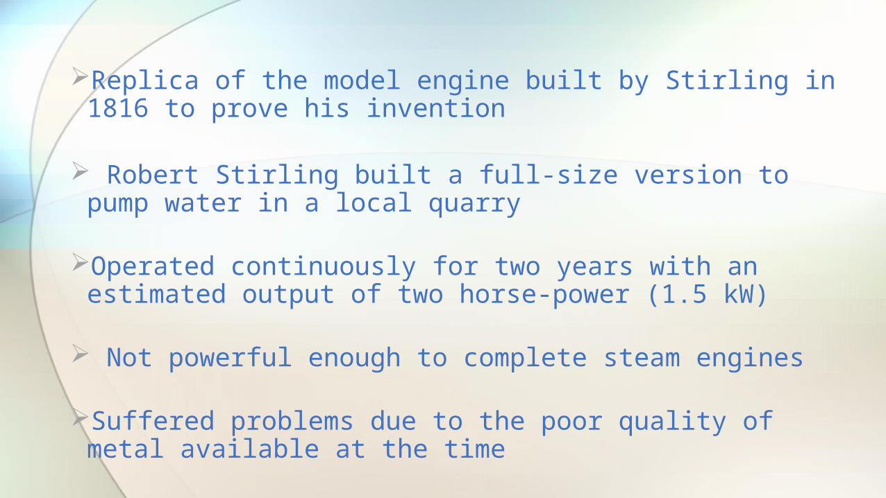
Replica of the model engine built by Stirling in 1816 to prove his invention
Robert Stirling built a full-size version to pump water in a local quarry
Operated continuously for two years with an estimated output of two horse-power (1.5 kW)
Not powerful enough to complete steam engines
Suffered problems due to the poor quality of metal available at the time
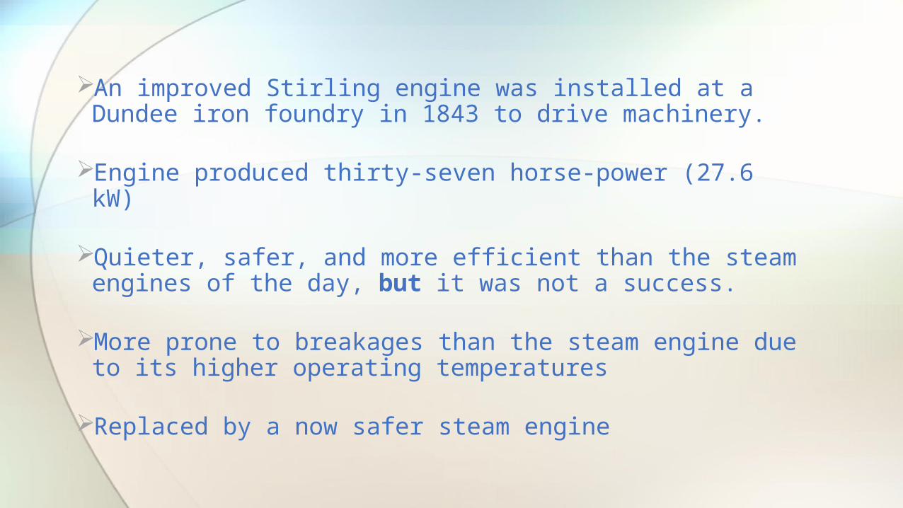
An improved Stirling engine was installed at a Dundee iron foundry in 1843 to drive machinery.
Engine produced thirty-seven horse-power (27.6 kW)
Quieter, safer, and more efficient than the steam engines of the day, but it was not a success.
More prone to breakages than the steam engine due to its higher operating temperatures
Replaced by a now safer steam engine
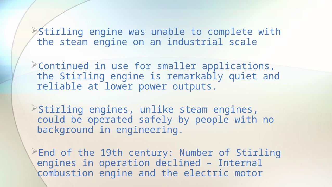
Stirling engine was unable to complete with the steam engine on an industrial scale
Continued in use for smaller applications, the Stirling engine is remarkably quiet and reliable at lower power outputs.
Stirling engines, unlike steam engines, could be operated safely by people with no background in engineering.
End of the 19th century: Number of Stirling engines in operation declined – Internal combustion engine and the electric motor
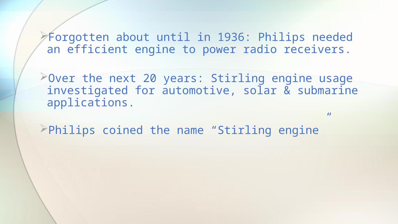
Forgotten about until in 1936: Philips needed an efficient engine to power radio receivers.
Over the next 20 years: Stirling engine usage investigated for automotive, solar & submarine applications.
Philips coined the name “Stirling engine”
Automobile TechnologySolar energyComputer chip coolingBackup power supply for submarines
Application of the Stirling engine
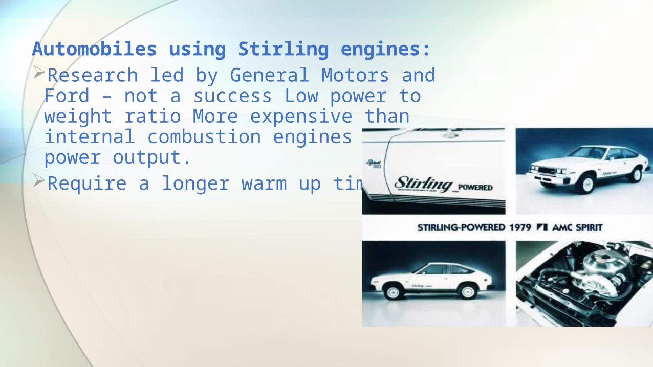
Automobiles using Stirling engines:Research led by General Motors and Ford –
not a success Low power to weight ratio More expensive than internal combustion engines for same power output.
Require a longer warm up time.
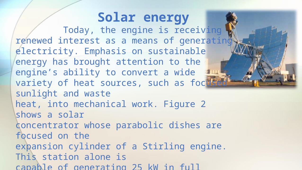
Solar energy Today, the engine is receiving renewed interest as a means of generating electricity. Emphasis on sustainable energy has brought attention to the engine’s ability to convert a wide variety of heat sources, such as focused sunlight and wasteheat, into mechanical work. Figure 2 shows a solarconcentrator whose parabolic dishes are focused on theexpansion cylinder of a Stirling engine. This station alone iscapable of generating 25 kW in full sunlight, enough topower a mid-sized house. The engines can also beretrofitted to existing power stations, where they canscavenge waste heat from the cooling systems to generate electricity.

A Stirling engine is a reversible system; given mechanical energy, it can function as a heat pump or cooling system. Below -40° C, there are no refrigerants suitable for use in a Rankine style cooler. Since the Stirling engine relies only on the input of mechanical energy to supply a temperature gradient, it is a highly competitive method of cooling in the cryogenic market. Similarly, a heat pump using a Stirling system takes advantage of the developed temperature gradient to move ambient heat from the environment into a space, such as abuilding.
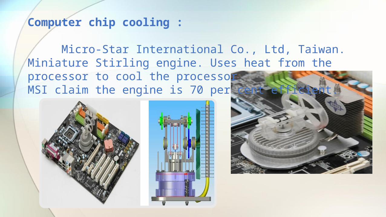
Computer chip cooling :
Micro-Star International Co., Ltd, Taiwan. Miniature Stirling engine. Uses heat from the processor to cool the processorMSI claim the engine is 70 per cent efficient.

Stirling engine powered submarines :
Remarkably quite – backup to primary modern diesel-electric engines when a silent approach is required Stirling engines are used to power a 75kW generator.
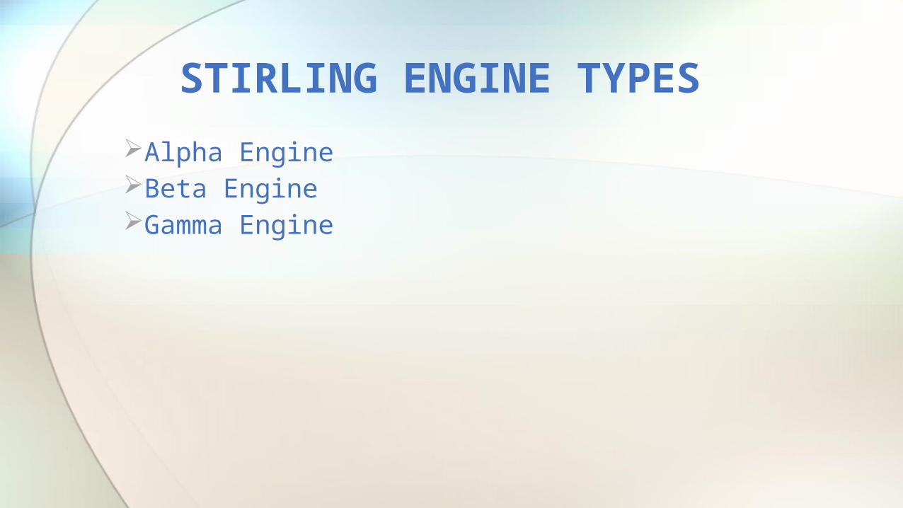
Alpha Engine Beta Engine Gamma Engine
STIRLING ENGINE TYPES
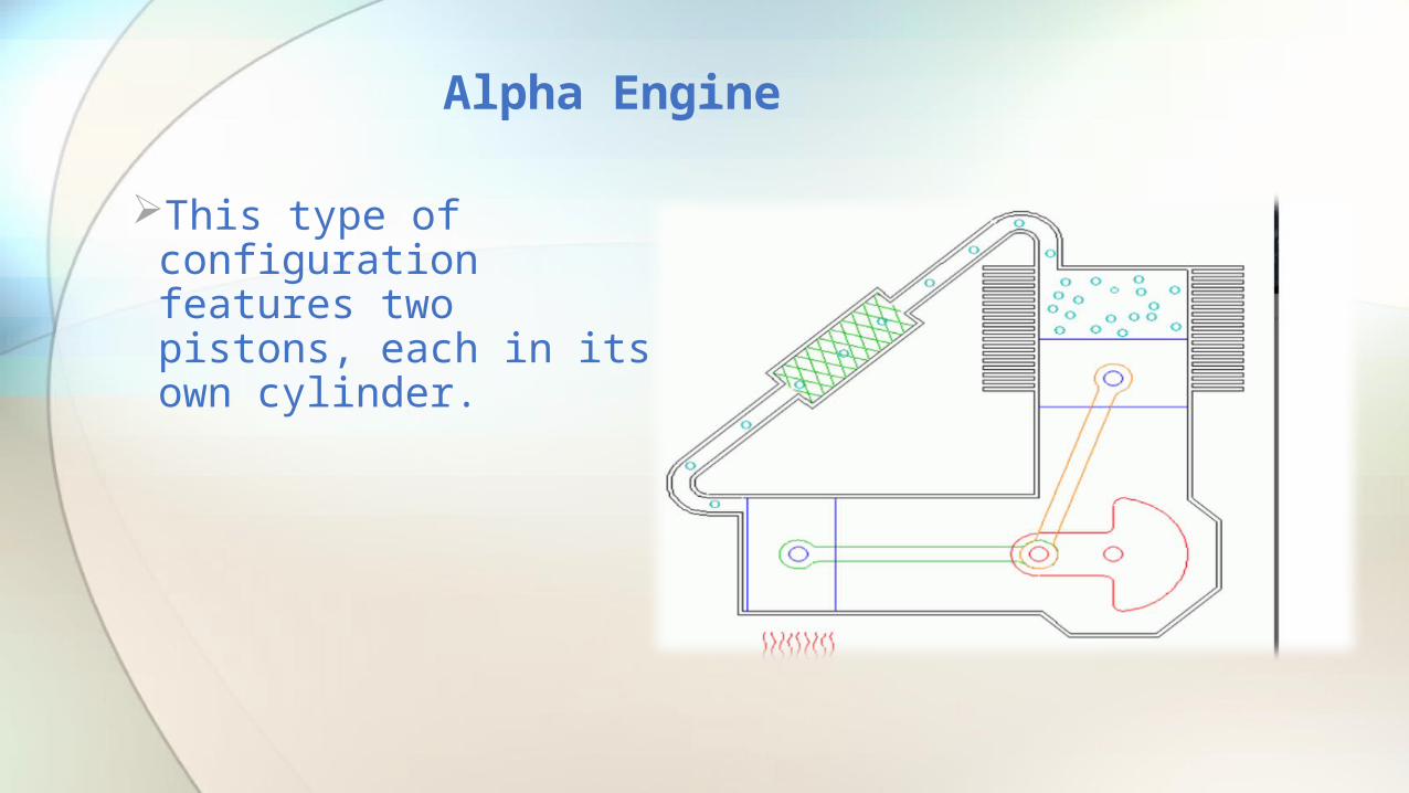
This type of configuration features two pistons, each in its own cylinder.
Alpha Engine
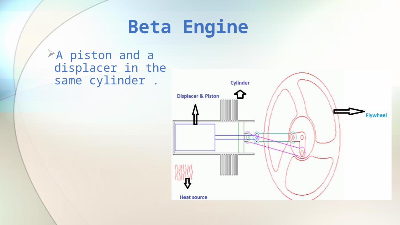
A piston and a displacer in the same cylinder .
Beta Engine
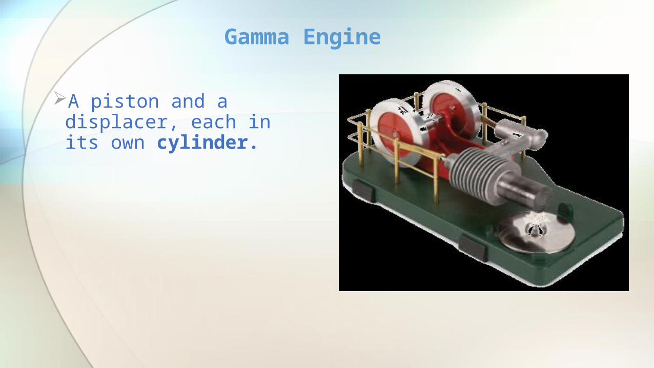
A piston and a displacer, each in its own cylinder.
Gamma Engine

NowWe Are Using The Gamma Type Engine

How does the Stirling engine work?
Piston linked to a circular disc known as a flywheel.
Flywheel converts linear movement to rotational movement.
Flywheel’s momentum needed for continuous operation.
Mechanical energy generated from temperature difference.
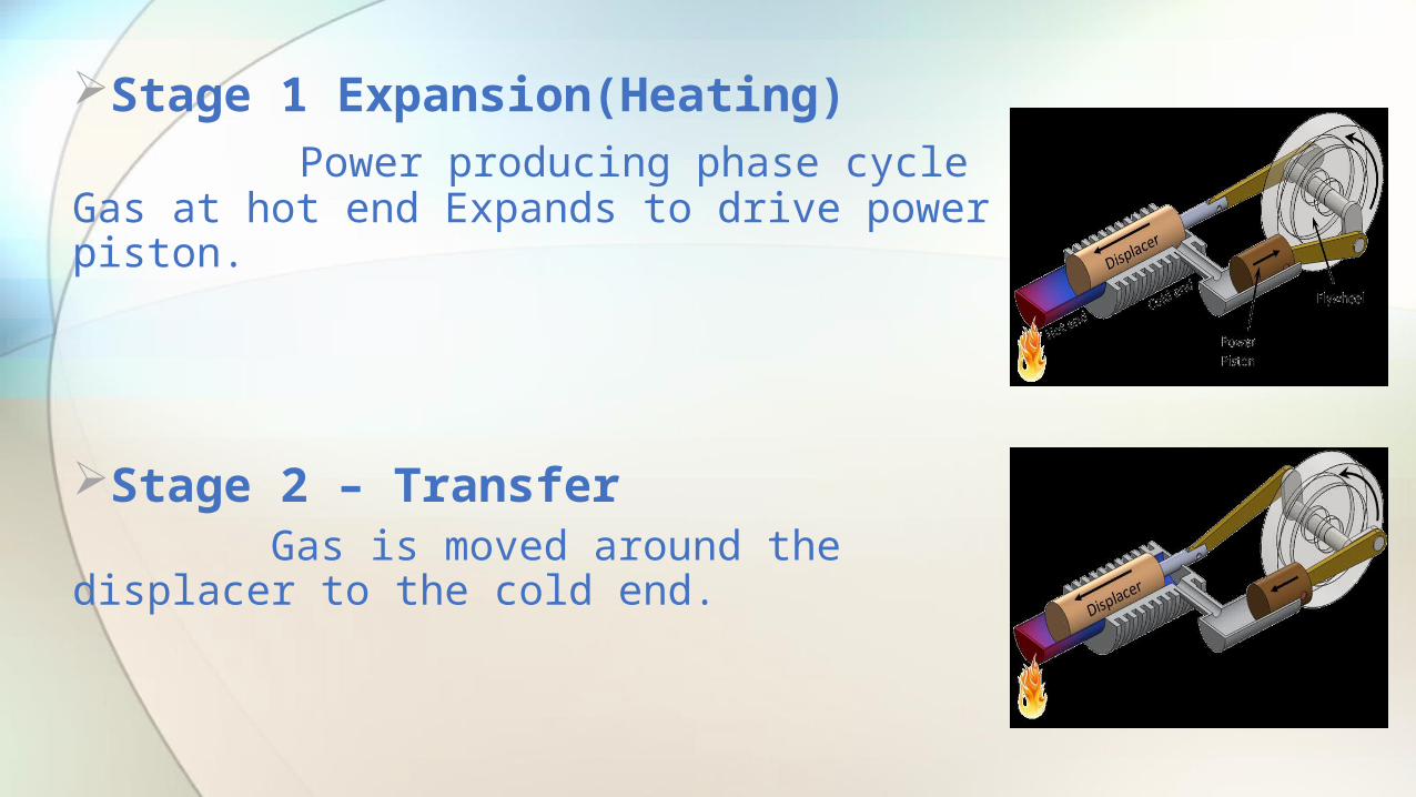
Stage 1 Expansion(Heating) Power producing phase cycle Gas at hot end Expands to drive power piston.
Stage 2 – Transfer Gas is moved around the displacer to the cold end.
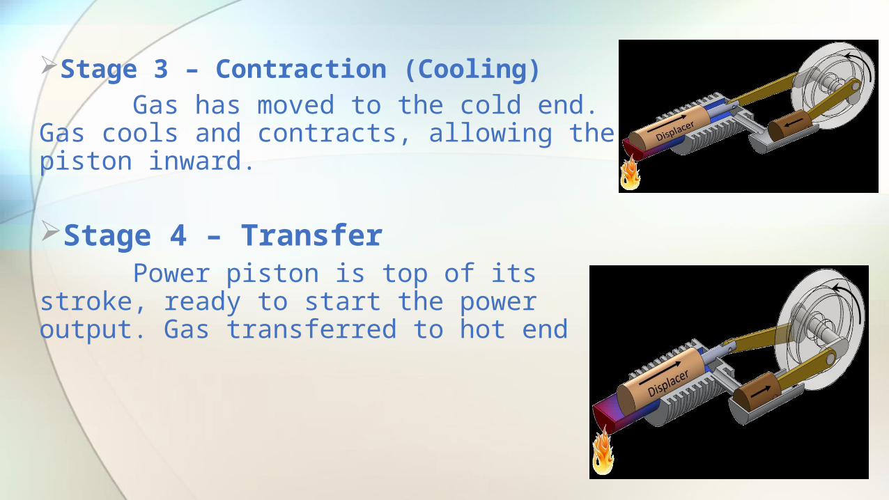
Stage 3 – Contraction (Cooling) Gas has moved to the cold end. Gas cools and contracts, allowing the piston inward.
Stage 4 – Transfer Power piston is top of its stroke, ready to start the power output. Gas transferred to hot end

Basic ComponentsA STIRLING engine consists of a number of basic
components, which may vary in design depending on the type and configuration. The most basic are outlined as follows….
FLYWHEEL CYLINDERPISTONCONNECTING RODDISPLACERPISTON RING OIL RING
STIRLING ENGINE MAIN COMPONENTS

DESIGNING OFSTIRLING ENGINE

FLYWHEEL

A flywheel is a rotating mechanical device that is used to store rotational energy. Flywheels have a significant moment of inertia and thus resist changes in rotational speed. The amount of energy stored in a flywheel is proportional to the square of its rotational speed. Energy is transferred to a flywheel by applying torque to it, thereby increasing its rotational speed, and hence its stored energy. Conversely, a flywheel releases stored energy by applying torque to a mechanical load, thereby decreasing the flywheel's rotational speed.
FLYWHEEL
Common uses of a flywheel include: Providing continuous energy when the
energy source is discontinuous. For example, flywheels are used in reciprocating engines because the energy source, torque from the engine, is intermittent.
Delivering energy at rates beyond the ability of a continuous energy source. This is achieved by collecting energy in the flywheel over time and then releasing the energy quickly, at rates that exceed the abilities of the energy source.
Controlling the orientation of a mechanical system. In such applications, the angular momentum of a flywheel is purposely transferred to a load when energy is transferred to or from the flywheel.

CYLINDER
A piston is seated inside each cylinder by several metal piston rings fitted around its outside surface in machined grooves; typically two for compressional sealing and one to seal the oil. The rings make near contact with the cylinder walls riding on a thin layer of lubricating oil; essential to keep the engine from seizing and necessitating a cylinder wall's durable surface.
During the earliest stage of an engine's life, its initial breaking-in or running-in period, small irregularities in the metals are encouraged to gradually form congruent grooves by avoiding extreme operating conditions. Later in its life, after mechanical wear has increased the spacing between the piston and the cylinder (with a consequent decrease in power output) the cylinders may be machined to a slightly larger diameter to receive new sleeves (where applicable) and piston rings, a process sometimes known as reboring .
CYLINDER
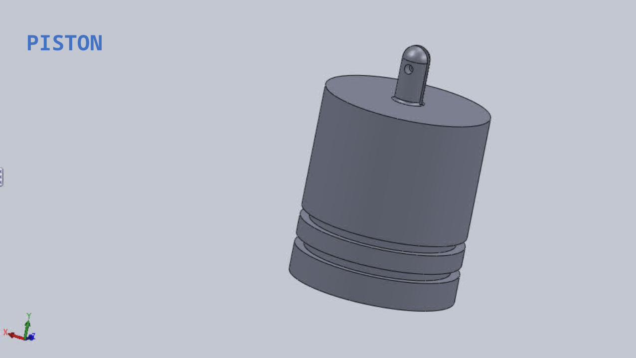
PISTON

A piston is a component of reciprocating engines, reciprocating pumps, gas compressors and pneumatic cylinders, among other similar mechanisms. It is the moving component that is contained by a cylinder and is made gas-tight by piston rings. In an engine, its purpose is to transfer force from expanding gas in the cylinder to the crankshaft via a piston rod and/or connecting rod. In a pump, the function is reversed and force is transferred from the crankshaft to the piston for the purpose of compressing or ejecting the fluid in the cylinder. In some engines, the piston also acts as a valve by covering and uncovering ports in the cylinder wall.
PISTON

PISTON RING

A piston ring is a split ring that fits into a groove on the outer diameter of a piston in a reciprocating engine such as an internal combustion engine or steam engine.
PISTON RING
The three main functions of piston rings in reciprocating engines are :
1.Sealing the combustion chamber so that there is no transfer of gases from the combustion chamber to the crank.2.Supporting heat transfer from the piston to the cylinder wall.3.Regulating engine gases consumption.
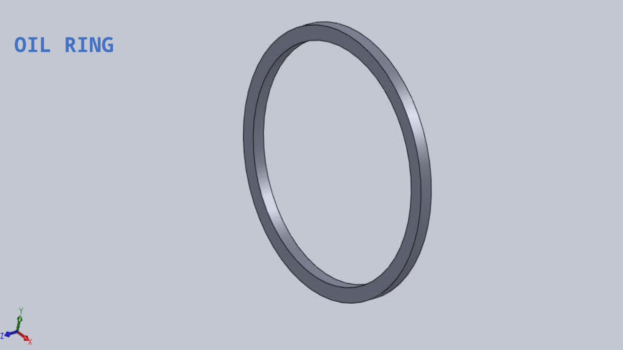
OIL RING

Oil ring is used for If the lubrication is passing through at top of the cylinder and that time the oil ring is stop the oil.
It is placed on bottom of the piston.
OIL RING
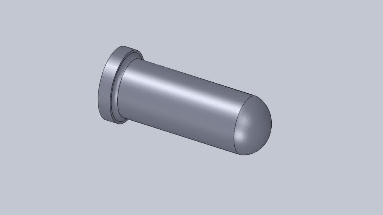
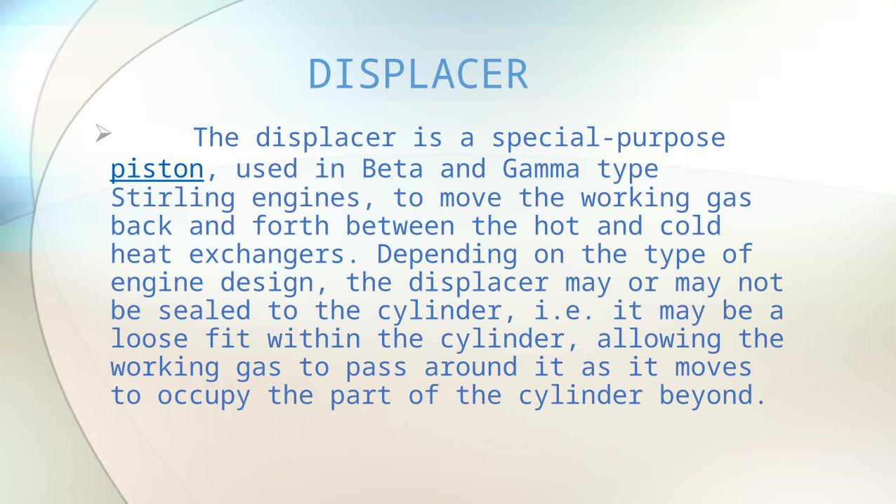
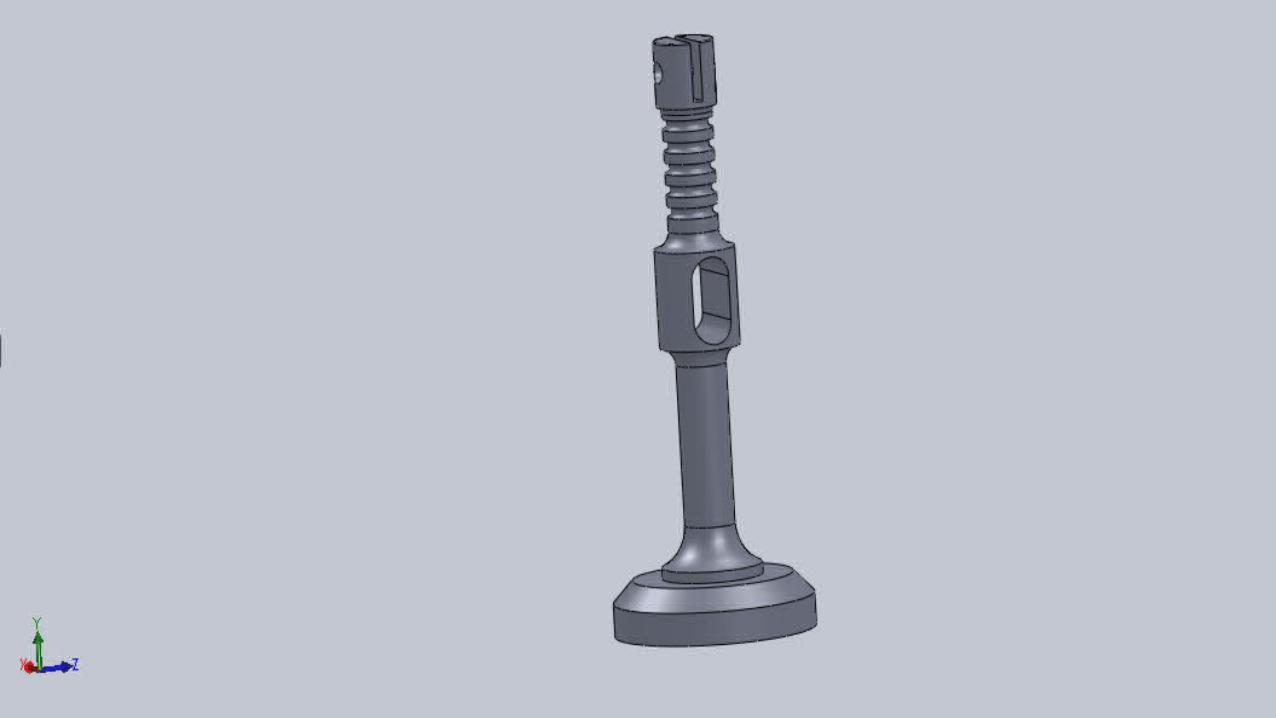
The displacer is a special-purpose piston, used in Beta and Gamma type Stirling engines, to move the working gas back and forth between the hot and cold heat exchangers. Depending on the type of engine design, the displacer may or may not be sealed to the cylinder, i.e. it may be a loose fit within the cylinder, allowing the working gas to pass around it as it moves to occupy the part of the cylinder beyond.
DISPLACER

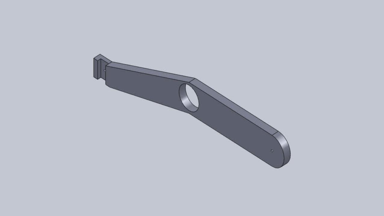
CONNECTING ROD
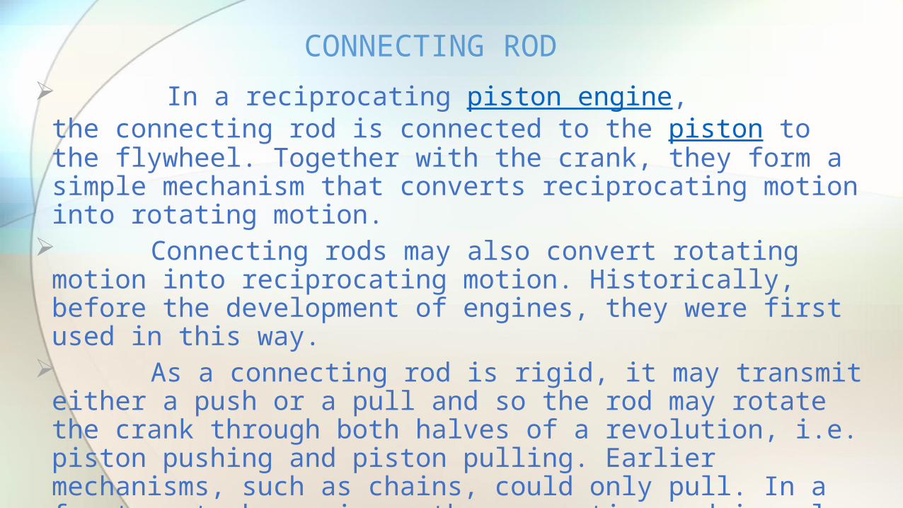
In a reciprocating piston engine, the connecting rod is connected to the piston to the flywheel. Together with the crank, they form a simple mechanism that converts reciprocating motion into rotating motion.
Connecting rods may also convert rotating motion into reciprocating motion. Historically, before the development of engines, they were first used in this way.
As a connecting rod is rigid, it may transmit either a push or a pull and so the rod may rotate the crank through both halves of a revolution, i.e. piston pushing and piston pulling. Earlier mechanisms, such as chains, could only pull. In a few two-stroke engines, the connecting rod is only required to push.
Today, connecting rods are best known through their use in internal combustion piston engines, such as automotive engines. These are of a distinctly different design from earlier forms of connecting rods, used in steam engines and steam locomotives.
CONNECTING ROD

FINALEY ASSEMBLE THIS PARTS AND RUNNING THE ENGINE

FINAL ASSEMBLING
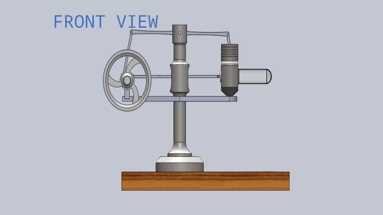
FRONT VIEW
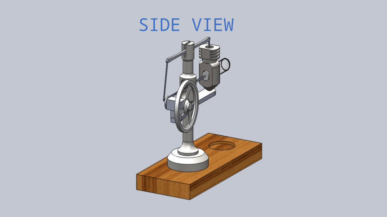
SIDE VIEW
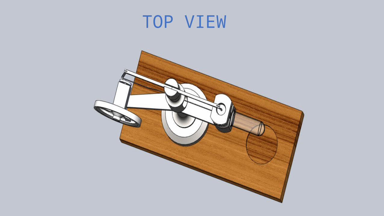
TOP VIEW

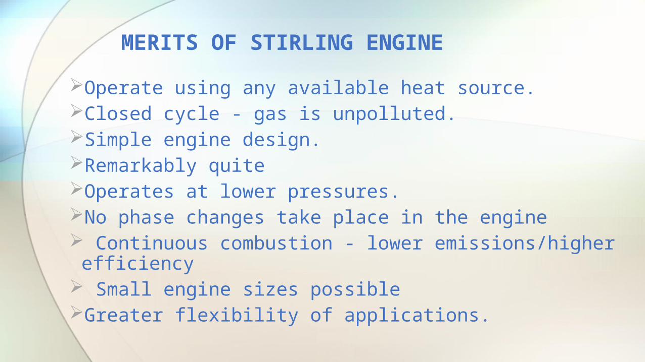
Operate using any available heat source.Closed cycle - gas is unpolluted.Simple engine design. Remarkably quite Operates at lower pressures. No phase changes take place in the engine Continuous combustion - lower emissions/higher
efficiency Small engine sizes possible Greater flexibility of applications.
MERITS OF STIRLING ENGINE

Low power to weight ratio More expensive than internal combustion engines for
same power output. Not self-starting. Require a longer warm up time Efficiency drops if the temperature difference between
the hot and cold ends decreases. Difficult to vary the power output Sealing of Stirling engines is extremely difficult.
DEMERITS OF STIRLING ENGINE

THANK YOU


