Page 1
Power production from a car exhaust heat recovery system
utilising thermoelectric generators and heat pipes
A thesis submitted in fulfilment of the requirements for the degree of
Doctor of Philosophy (Mechanical and Manufacturing engineering)
Bradley Glenn Orr
Bachelor of Engineering (Automotive)
School of Engineering (Aerospace Mechanical and Manufacturing Engineering)
College of Science Engineering and Health
RMIT University
October 2016
Page 2
i
Declaration
I certify that except where due acknowledgement has been made, the work is that of the
author alone; the work has not been submitted previously, in whole or in part, to qualify for
any other academic award; the content of the thesis/project is the result of work which has
been carried out since the official commencement date of the approved research program; any
editorial work, paid or unpaid, carried out by a third party is acknowledged; and, ethics
procedures and guidelines have been followed.
Bradley Glenn Orr
26th October 2016
Page 3
ii
Acknowledgements
I would like to thank RMIT University for the opportunity to do this exciting project. I would
not have been able to commence my PhD without being awarded an Australian Postgraduate
award (APA) scholarship from RMIT so for this I am very much grateful.
I would like to thank my primary supervisor, Professor Akbarzadeh. He first introduced me to
thermoelectric generators and heat pipes as a first year undergraduate engineering student. I
was so interested in these devices that it sparked my imagination on how they can be used for
automotive purposes. I would not have been doing this project if you did not do that demo
years ago. I hope you continue to inspire other students in the future as you did with me.
I would like to thank my secondary supervisor, Dr Petros Lappas for his help throughout my
candidature. His assistance on developing a theoretical model and his knowledge on car
engines is greatly appreciated.
Many thanks to my final year project students Julian Taglieri and Christopher Mazraany.
Their help testing the TEGs and testing the naphthalene heat pipe heat exchanger is much
appreciated.
Thank you to the workshop for making components for my project when required and their
assistance in setting up my lab.
Thank you to Fujikura Japan for supplying heat pipes at a reduced cost for my project.
Without this assistance my project might not have been possible. Thank you to Dr Mochizuki
san, Dr Saito san Dr Randeep san for the opportunity to undertake an internship at Fujikura
during my candidature. This experience was very helpful for my project.
To my friends in the EnergyCARE group, many thanks for your help throughout my
candidature. I hope you have found my help of some assistance too.
Finally, thank you to my parents for their years of support. Thanks Dad for your handyman
skills when required.
Page 4
iii
Abstract
The use of fossil fuels in a car internal combustion engine results in the release of CO2 gasses
to the atmosphere. These CO2 gasses are one of the main causes of global warming. Efforts
are being made to improve the efficiency of the internal combustion engine but as it is a
relatively mature technology, improvements will start to plateau. Alternative methods to
improve the overall efficiency of a car must be investigated. One possible area of
investigation is the use of an exhaust heat recovery system. These systems have yet to be
implemented in a mass produced car but they have the potential to reduce the fuel
consumption of a car. A majority of the energy in the fuel used for a car is converted into
heat. A large proportion of this heat is present in the exhaust gases. An exhaust heat recovery
system would recover some of this heat and convert it into electricity to charge the car
battery. This system could potentially reduce the load on a car alternator or completely
replace it. The alternator draws power from the engine so reducing the load on the engine will
result in a reduction in fuel consumption. CO2 emissions are directly proportional to fuel
consumption.
Two potential technologies identified for use in an exhaust heat recovery system were
thermoelectric generators (TEGs) and heat pipes. TEGs are small tile shaped devices that
create electricity when there is a temperature difference over the top and bottom surfaces.
Heat pipes are small cylindrical shaped devices which are used to transfer heat relatively long
distances with minimal thermal resistance. A design has been proposed which uses the heat
pipes to transfer heat from the exhaust gases to the TEGs and the TEGs convert some of this
heat into electricity. The novelty of this design is that the system is completely passive and
solid state.
Throughout the candidature, testing has been undertaken on TEGs, naphthalene heat pipes
and prototype exhaust heat recovery systems. The naphthalene heat pipes were shown to have
potential for high temperature heat transfer applications. An equation derived to predict TEG
power output as a function of temperature difference has been validated by testing the TEGs
and this equation was used for modelling of the second prototype exhaust heat recovery
system. This second prototype exhaust heat recovery system produced a maximum of 38W of
electricity at a thermal efficiency of 2.48%. The system consisted of eight 62mm by 62mm
TEGs. If a full size exhaust heat recovery system with the same TEG thermal efficiency and
heat exchanger effectiveness was fitted to a car, the predicted reduction in fuel consumption
and CO2 emissions would be 1.57%.
Page 5
iv
Contents
Declaration………………………………………………………………………….... i
Acknowledgments……………………………………………………………………. ii
Abstract………………………………………………………………………………. iii
Contents………………………………………………………………………………. iv
Introduction…………………………………………………....................................... 1
1.1 Background…………………………………………………………………. 1
1.2 Thermoelectric generators………………………………………………….. 2
1.3 Heat pipes……………………………………………………………........... 5
1.4 Thesis structure………………………………………………………........... 8
1.5 Publications and recognition………………………………………………... 9
Literature review………………………………………………………………........... 10
2.1 Exhaust gas temperature and mass flow rates……………………………… 10
2.2 TEGs and their materials…………………………………………………… 10
2.3 Predicting the power output of TEGs………………………………………. 12
2.4 Applications and types of heat pipes……………………………………….. 12
2.5 System designs………………………………………………………............ 13
2.5.1 Typical exhaust heat recovery designs using TEGs………………. 13
2.5.2 Alternative exhaust heat recovery designs…………………........... 14
2.6 Exhaust heat recovery systems from OEMs…………………………........... 15
Page 6
v
2.7 Issues with exhaust heat recovery systems…………………………………. 16
2.7.1 Controlling the TEG temperature…………………………………. 16
2.7.2 Other issues……………………………………………………….. 18
2.8 Use of heat pipes in power generating and heat recovery systems…………. 18
2.8.1 Car heat recovery systems utilising TEGs and heat pipes…............ 18
2.8.2 Other systems………………………………………………........... 22
2.9 Gaps in the literature………………………………………………………... 24
Research method, aims and questions………………………………………………... 25
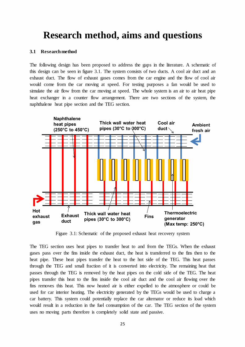
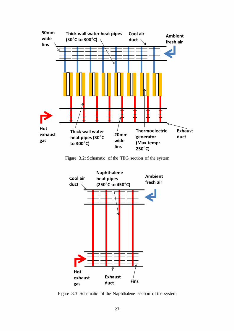
3.1 Research method……………………………………………………………. 25
3.2 Research aims………………………………………………………………. 28
3.3 Research questions………………………………………………………….. 28
A review of car waste heat recovery systems utilising thermoelectric generators and
heat pipes……………………………………………………………………………... 29
Electricity generation from an exhaust heat recovery system utilising thermoelectric
cells and heat pipes………………………………….................................................... 30
Validating an alternative method to predict thermoelectric generator
performance…………………………………………………………………………... 31
Experimental testing of a car exhaust heat recovery system utilising TEGs and heat
pipes…………………………………………………………………………………... 32
7.1 Journal paper……………………………………………………………… 32
7.2 Supplementary information…………………………………………………. 32
Page 7
vi
Operating characteristics of naphthalene heat pipes…………………………………. 37
8.1 Introduction………………………………………………………………...... 39
8.2 Testing an individual naphthalene heat pipe………………………………... 39
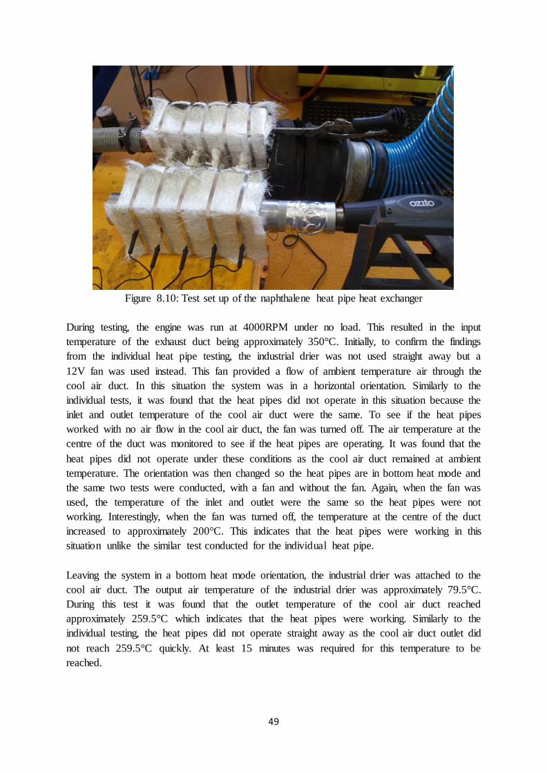
8.3 Testing a naphthalene heat pipe heat exchanger…………………………….. 48
8.4 Conclusion…………………………………………………………………... 53
8.5 Supplementary information…………………………………………………. 54
Conclusion and future work………………………………………………………….. 55
9.1 Conclusion…………………………………………………………….......... 55
9.2 Future work…………………………………………………………………. 56
Bibliography………………………………………………………………………….. 57
Page 8
1
Introduction
1.1 Background
Increasing the efficiency of energy use is becoming more and more important in today’s
society because of the linked issues of global warming and dwindling oil supplies. There is
still a heavy reliance on power production from fossil fuels. When this fuel is used, carbon
dioxide (CO2) is released to the atmosphere. Unfortunately CO2 is a greenhouse gas. When
light from the sun reaches the earth, some light is reflected but much of this energy is
absorbed by the atmosphere and the earth surface which generates heat. Heated objects
radiate infrared radiation back out to space but greenhouse gases such as CO2 block this
radiation and essentially trap this energy. With more greenhouse gases present, more energy
will be trapped and this creates the global warming effect.
Greenhouse gases have always been present as these gases are what keep the earth at
relatively comfortable temperatures but adding extra gases are known to cause issues such as
extreme weather events, melting of polar ice caps, etc. CO2 emissions are the main cause for
concern but there other greenhouse gases. Methane is one example and is known to have per
unit mass a higher global warming effect. Water vapour is another example. The sheer
amount of CO2 emissions from burning fossil fuels makes CO2 the main cause for concern.
Releasing of CO2 into the atmosphere is not the main issue but what is important is where the
CO2 emissions have come from. For example, the use of ethanol as a car fuel will release
CO2 when used but if the ethanol comes from a crop, the next crop will absorb the same
amount of CO2 from the atmosphere making the whole process carbon neutral. The same can
be said for burning wood in a fire as when a tree is cut down and used as fire wood, another
tree can grow in its place and absorb the CO2 emitted. When fossil fuels are used, this is not
the case. The source of carbon in fossil fuels is from bio matter and plant mass which is
millions of years old. This carbon is deep underground and has no interaction with the
atmosphere. When fossil fuels are used, the CO2 is released to the atmosphere adding to the
natural levels of CO2 in the atmosphere and causing an increased global warming effect. This
is why the use of fossil fuels needs to be reduced.
The automotive industry has been targeted to reduce the fuel consumption and CO2 emissions
of their manufactured cars. This is despite the fact that the carbon footprint of the automotive
industry is only 17% of the total greenhouse gas emissions as stated by Hertwich & Peters
(2009). This figure does change from country to country but in all cases the automotive
industry does not have the largest carbon footprint. One of the reasons why the automotive
industry is targeted is because the impact of change is quicker than for example the power
generating industry. When a power plant is commissioned, its life span is usually around 50
years therefore when it comes time for replacement, only then is newer more efficient
technology introduced. People typically replace cars every ten years therefore newer more
efficient technology is introduced relatively quickly and the impacts of the change are more
Page 9
2
immediate. The mandatory use of catalytic converters in cars is a highly visible example of
how emissions regulations can quickly make an impact as smog levels drastically reduced
after their introduction. CO2 emission regulations will have a similar effect.
Due to the issue of fossil fuels being a limited resource, as supply reduces and demand
increases, the price of oil will inevitably increase. Although automotive companies are forced
to reduce CO2 emissions and consequently fuel consumption through regulations, the rising
cost of fuels means it is in an automotive company’s interest to reduce the fuel consumption
of their cars. In the mid-1900s when energy was cheap, efficiency was not an important
factor when considering purchasing a car but now low fuel consumption is a big selling point.
To do this the car engine efficiency must improve. The internal combustion engine is a
relatively mature technology therefore it is getting more difficult to obtain efficiency gains.
Rather than attempting to develop more efficient engines, some automotive companies
developed hybrid systems to improve the overall efficiency of the drivetrain. These systems
allow the engine to work in optimal operating conditions and allow for use of kinetic energy
recovery systems. Reducing weight and aerodynamic drag has also become more of a focus.
To further reduce CO2 emissions and fuel consumption, other methods to improve the overall
efficiency of the car need to be developed.
A general rule of thumb is that a third of the energy input into an internal combustion engine
is converted into mechanical work with another third of the energy in the form of heat in the
engine coolant and the final third in the form of heat in the exhaust gases. This means there is
a lot of wasted energy in the form of heat which is dissipated to the atmosphere through the
exhaust gases and cooling system. It is possible to recover some of this heat and convert it
into electrical power using a heat recovery system and heat engine. The engine coolant must
be maintained to a temperature of approximately 90°C which means it is a low grade heat.
This limits the recovery potential from the coolant because the lower temperature will lead to
lower heat engine thermal efficiencies. Exhaust gas is a higher grade heat due to the higher
temperatures present allowing for a potentially more efficient heat recovery system. This is
why an exhaust heat recovery is more viable than an engine coolant heat recovery system
despite the energy input into the exhaust and coolant being approximately the same.
If a heat engine is used to recover heat from the exhaust gases, the electricity generated could
be used to charge the car battery. Typically an alternator connected to the engine is used to
charge the car battery. Implementing an exhaust heat recovery system could potentially
replace or reduce the load on the alternator. Reducing the load on the alternator will reduce
the load on the engine which consequently reduces the fuel consumption.
1.2 Thermoelectric generators
Thermoelectric generators make use of what is known as the Seebeck effect. When some
materials are subjected to a temperature difference from one side to the other, a voltage is
generated from one side to the other. Materials that create a higher voltage at the same
temperature difference have a higher Seebeck coefficient. For this reason, thermoelectric
Page 10
3
generators use materials with a high Seebeck coefficient. The Seebeck coefficient of a
material is proportional to the material electrical conductivity and inversely proportional to
the material thermal conductivity.
Typically a TEG consists of many N type and P type material elements connected electrically
in series but thermally in parallel as described by Han et al (2010). This is shown in figure
1.1. When there is a temperature difference over the TEG, a voltage is created and
consequently power can be generated. A higher temperature difference will result in a higher
power output. The difference between the N type and P type materials is with the same
temperature difference, the voltage generated will be opposite. As all the elements are
connected in series, the small voltage generated by each element adds up to generate usable
voltages. The amount of power produced by the TEG is proportional to the amount of
thermoelectric material used. TEGs can be designed to produce different voltages and
currents where needed. For example, two TEGs of the same surface area but differing
amounts of elements will produce different voltages and currents. The TEG with more
elements will produce a higher voltage but a lower current. When used in a system, a number
of TEGs can be connected electrically in different combinations of series and parallel to
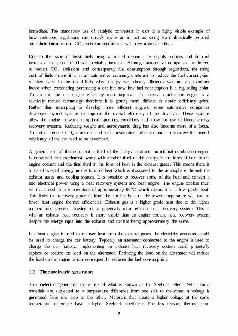
produce the desired voltage and current. An image of a TEG can be seen in figure 1.2.
Figure 1.1: Schematic of a thermoelectric generator
Page 11
4
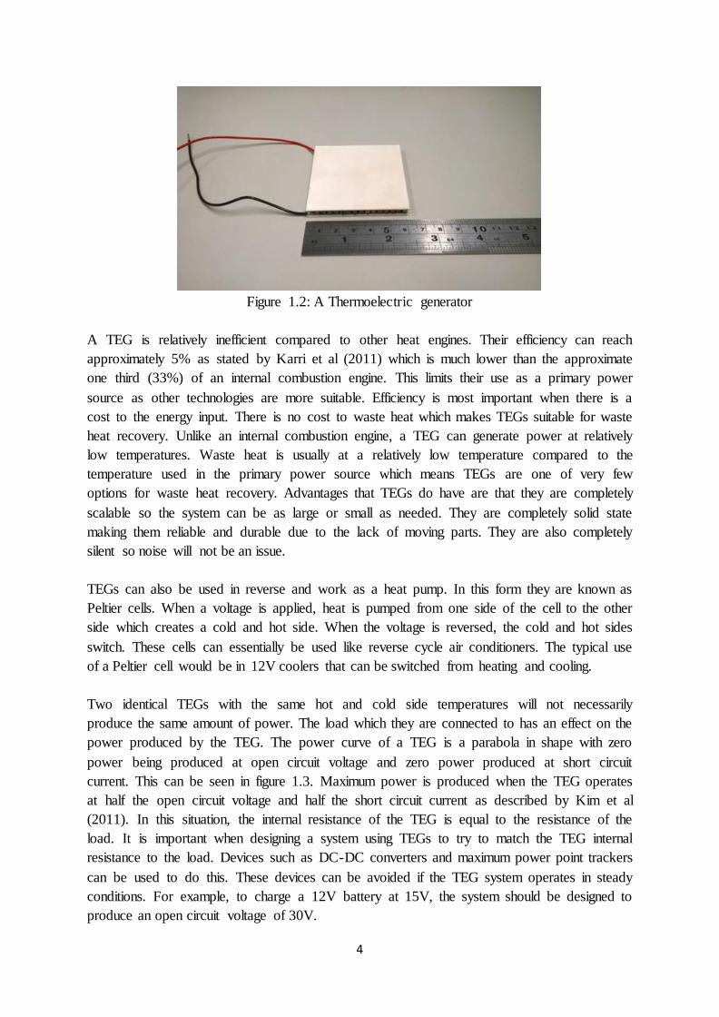
Figure 1.2: A Thermoelectric generator
A TEG is relatively inefficient compared to other heat engines. Their efficiency can reach
approximately 5% as stated by Karri et al (2011) which is much lower than the approximate
one third (33%) of an internal combustion engine. This limits their use as a primary power
source as other technologies are more suitable. Efficiency is most important when there is a
cost to the energy input. There is no cost to waste heat which makes TEGs suitable for waste
heat recovery. Unlike an internal combustion engine, a TEG can generate power at relatively
low temperatures. Waste heat is usually at a relatively low temperature compared to the
temperature used in the primary power source which means TEGs are one of very few
options for waste heat recovery. Advantages that TEGs do have are that they are completely
scalable so the system can be as large or small as needed. They are completely solid state
making them reliable and durable due to the lack of moving parts. They are also completely
silent so noise will not be an issue.
TEGs can also be used in reverse and work as a heat pump. In this form they are known as
Peltier cells. When a voltage is applied, heat is pumped from one side of the cell to the other
side which creates a cold and hot side. When the voltage is reversed, the cold and hot sides
switch. These cells can essentially be used like reverse cycle air conditioners. The typical use
of a Peltier cell would be in 12V coolers that can be switched from heating and cooling.
Two identical TEGs with the same hot and cold side temperatures will not necessarily
produce the same amount of power. The load which they are connected to has an effect on the
power produced by the TEG. The power curve of a TEG is a parabola in shape with zero
power being produced at open circuit voltage and zero power produced at short circuit
current. This can be seen in figure 1.3. Maximum power is produced when the TEG operates
at half the open circuit voltage and half the short circuit current as described by Kim et al
(2011). In this situation, the internal resistance of the TEG is equal to the resistance of the
load. It is important when designing a system using TEGs to try to match the TEG internal
resistance to the load. Devices such as DC-DC converters and maximum power point trackers
can be used to do this. These devices can be avoided if the TEG system operates in steady
conditions. For example, to charge a 12V battery at 15V, the system should be designed to
produce an open circuit voltage of 30V.
Page 12
5
Figure 1.3: The I-V curve and power curve of a TEG
1.3 Heat pipes
Heat pipes are devices that are used to transfer heat from point A to point B with minimal
thermal resistance. They have effective thermal conductivities which can be magnitudes
higher than copper. They don’t work using simple conduction but make use of latent heat
transfer. A typical use of heat pipes is in laptop computers where they are used to transfer
heat from the CPU to a finned heat sink exposed to cool air. Heat pipes can be used in many
heat transfer applications though.
A heat pipe is essentially a metallic pipe which is sealed at both ends. On the inner surface of
the pipe is a wick structure. This wick can be in the form of a mesh, powder or fibres. A
small amount of working fluid is added which completely saturates the wick. The pipe is
completely de-gassed so it has no air inside.
Heat pipes consist of three different sections: the evaporator section, the adiabatic section and
the condenser section. When heat is applied at the evaporator section, the working fluid in the
wick vaporises in this area. The liquid vaporises at relatively low temperatures because of the
lower than atmospheric pressure in the pipe (In the case of water at ambient temperature).
This vapour moves past the adiabatic section and up to the condenser section. No heat
transfer occurs in the adiabatic section which is why it is usually insulated. As the condenser
section is being cooled, the vapour condenses back into liquid phase which releases latent
heat. The liquid then moves through the wick back to the evaporator section and the cycle
continues. This process is described by Chaudhry et al (2012). A schematic of a heat pipe in
operation can be seen in figure 1.4. The working fluid inside the pipe is always at a saturated
pressure/temperature. Therefore as the average temperature of the heat pipe increases, the
corresponding saturation pressure inside the pipe increases.
Page 13
6
Figure 1.4: Schematic of a heat pipe
Due to their method of operation, heat pipes are completely solid state and completely
passive. No fans or pumps are required to operate. No power inputs are required. This makes
them very reliable and low maintenance. Heat pipes can be as large or as small as required
plus are silent.
Heat pipes do have operating limits. There are limits of the operating temperatures and limits
to the maximum rate of heat transfer. Four main limits of heat transfer are the boiling limit,
entrainment limit, wicking limit and the sonic limit. The boiling limit occurs when the
temperature difference over the wick is equal to the maximum possible degree of
superheating of the liquid. When this occurs, boiling starts inside the wick which lowers
performance. The entrainment limit occurs due to the effects of viscosity between the vapour
and liquid. At high rates of heat transfer, the velocity of vapour is high. The liquid and vapour
travel in opposite directions therefore the effect of viscosity on the liquid from the vapour
prevents the liquid returning to the evaporator. The wicking limit occurs when the wick can’t
deliver the required mass flow rate of liquid to the evaporator for the rate of heat transfer. The
wicking limit changes with orientation because gravity can either assist or resist the delivery
of liquid to the evaporator. The sonic limit occurs when the rate of heat transfer is high
enough to require the vapour to travel at the speed of sound. The vapour speed can’t surpass
the speed of sound.
Page 14
7
The operating temperature limits of a heat pipe are very much dependent of the working fluid
selected. For example, with water as the working fluid, the heat pipe will not work below 0°C
because the water will be frozen. At higher temperatures, the pressure inside the pipe may
cause it to rupture which limits the maximum operating temperature. Heat pipes rely on latent
heat transfer therefore they will not work past the working fluid critical point temperature.
For water, this would be 374°C. Different working fluids are selected depending on the
intended heat pipe operating temperature due to their different properties. Yang et al (2012)
stated that for operating temperatures in the low/cryogenic range (1-200K), helium, argon,
neon and nitrogen are possible working fluids. For room temperature applications (200-
550K), water, methanol, ethanol, ammonia and acetone are possible working fluids. For the
medium temperature range (550-700K), organic working fluids such as biphenyl and
naphthalene can possibly be used. In the high temperature range (>700K), potassium, sodium
and silver are possible working fluids.
There are two different types of heat pipes: wicked heat pipes and thermosiphons. Wicked
heat pipes are just commonly known as heat pipes. The difference between the two is that one
contains a wick and the other does not. As thermosiphons do not contain a wick, they will
only work if the evaporator is below the condenser section. They rely on gravity to return the
liquid to the evaporator.
There are two different methods to degas a heat pipe. One is called the purging method and
the other is called the vacuum method. The purging method involves heating the working
fluid until it starts to boil. The vapour generated from the boiling pushes out the air in the
pipe. While the heat is still applied, after a set period of time the pipe is sealed so no air can
return into the pipe. When the heat is removed, the heat pipe cools and the internal pressure
falls below atmospheric pressure. The vacuum method uses a vacuum pump to remove the air
inside the pipe. After the pipe has been vacuumed the working fluid is added and then then
pipe is sealed.
Page 15
8
1.4 Thesis structure
This thesis was submitted using the “thesis with publications” method. A number of journal
papers were published throughout the candidature containing research undertaken for this
PhD. These journal papers will form chapters 4 - 7 of this thesis. The information contained
in these journal papers are as follows:
Chapter 4:
This review paper discusses the use of thermoelectric generators and heat pipes for car waste
heat recovery systems. The advantages and limitations of TEGs and heat pipes are considered
as compared to other waste heat recovery systems. Many different designs are discussed
explaining why that approach was taken.
Chapter 5:
A bench type, proof of concept model was produced to demonstrate how TEGs and heat
pipes can be used to produce electricity from an engine’s exhaust gas. In this case a small
50CC petrol engine was used as the supply of exhaust gases. This system was used to charge
a 12V motorcycle battery. Investigations on the performance of the system were undertaken.
(Acknowledgement: This system was built and tested before the commencement of
candidature. Additional testing and analysis was undertaken during the candidature which
forms the information in this chapter / journal paper.)
Chapter 6:
A TEG testing rig was created which allowed the performance of a number of different TEGs
to be tested under a number of different operating conditions. An equation was derived which
enabled the power to be predicted as a function of temperature difference. This equation was
then validated using experimental results.
Chapter 7:
A second prototype exhaust heat recovery system using TEGs and heat pipes was produced.
This system was designed for higher temperatures, higher rates of heat transfer and higher
power outputs because it was to be connected to a car exhaust pipe. A theoretical model was
created predicting the performance of the system. Testing was undertaken to validate the
theoretical model and find the maximum power output of the system. Investigations on the
potential fuel, cost and CO2 savings were also undertaken.
Page 16
9
1.5 Publications and recognition
The bibliographic details of the journal papers and conference papers created during the
candidature can be seen below. Papers with the candidate as second author are not shown.
Journal papers:
Orr, B, Akbarzadeh, A, Mochizuki, M & Singh, R 2016, 'A review of car waste heat recovery
systems utilising thermoelectric generators and heat pipes', Applied Thermal Engineering,
vol. 101, pp. 490-5.
Orr, B, Singh, B, Tan, L & Akbarzadeh, A 2014, 'Electricity generation from an exhaust heat
recovery system utilising thermoelectric cells and heat pipes', Applied Thermal Engineering,
vol. 73, no. 1, pp. 586-95.
Orr, B, Taglieri, J, Ding, LC & Akbarzadeh, A 2016, 'Validating an alternative method to
predict thermoelectric generator performance', Energy Conversion and Management, vol.
116, pp. 134-41.
Orr, B & Akbarzadeh, A 2016, 'Experimental testing of a car exhaust heat recovery system
utilising TEGs and heat pipes', SAE-A Vehicle Technology Engineer, vol. 2, no. 1.
Conference papers
Orr, B, Akbarzadeh, A & Lappas, P 2014, 'Predicting the performance of a car exhaust heat
recovery system that utilises thermoelectric generators and heat pipes', paper presented to
SOLAR2014, Melbourne, Australia.
Orr, BG, Akbarzadeh, A & Lappas, P 2015, 'Reducing Automobile CO2 Emissions with an
Exhaust Heat Recovery System Utilising Thermoelectric Generators and Heat Pipes', paper
presented to APAC18, Melbourne, Australia, <http://dx.doi.org/10.4271/2015-01-0051>.
Orr, BG, Akbarzadeh, A & Lappas, P, 2016 ‘An exhaust heat recovery system utilising
thermoelectric generators and heat pipes’, paper presented to Joint 18th IHPC and 12th IHPS,
Jeju, Korea.
The journal paper published with SAE-A (Society of Automotive Engineers – Australasia)
was awarded the postgraduate project award at the 2015 annual SAE-A MEEA (Mobility
Engineering Excellence Awards) presentation night. The prototype exhaust heat recovery
system shown in chapter 5 was entered into the 2015/2016 Honda powered invention
competition. This system come runner up in the public category. The conference paper
presented at the joint 18th IHPC (International heat pipe conference) and 12th IHPS
(International heat pipe symposium) won the best student paper award.
Page 17
10
Literature review
2.1 Exhaust gas temperature and mass flow rates
Hassan (2012) discussed exhaust gas temperatures throughout the exhaust system. Both
petrol and diesel engines were investigated and it was found that petrol engines have higher
average exhaust gas temperatures. This is mainly because diesel engines always run lean
therefore the heat energy in the burnt gases is mixed and diluted in with the unused air.
Temperatures at part and full load were also investigated. Due to the temperature limitations
of an exhaust heat recovery system using TEGs, this information will affect the possible
locations of the system. Temperatures range from 790°C at the exhaust manifold in a petrol
engine at full load to 100°C at the exhaust outlet in a diesel engine at part load.
Arias et al (2006) made a comparison between petrol and diesel engines and their energy
balance. Petrol engines have a higher percentage of energy in the exhaust gases compared to
diesel engines. There is also a comparison of efficiency between a coolant waste heat
recovery system and an exhaust heat recovery system. The exhaust heat recovery system had
the higher potential efficiency because of the higher temperatures present. The exhaust gas
temperatures stated are similar to those stated by Hassan (2012).
2.2 TEGs and their materials
Karri et al (2011) has made a comparison between two different types of TEG materials:
Bismuth Telluride and Quantum Well. The former is a commercially available product but
the latter is very useful for car exhaust heat recovery because it can handle higher
temperatures. It was found that increasing coolant flow may increase the power produced by
the TEGs but parasitic power losses may cancel out the gains.
Stobart & Milner (2009) discussed different types of thermoelectric materials. The most
popular form of thermoelectric material is Bismuth Telluride. TECs using this material are
typically used as heat pumps because of their favourable properties at close to room
temperature. Their use as generators is limited because their maximum hot side operating
temperature is relatively low. As they are widely used and mass produced, their cost is low
compared to other thermoelectric materials. Other materials and techniques have been used to
improve the power generation and efficiency of TEGs. Lead Telluride has been used as a
material in TEGs designed for power generation. These TEGs are able to handle the higher
temperatures. This means a larger temperature difference can be present and potentially more
power and higher efficiency can be achieved. Some TEGs have been manufactured with
segmented material. A material with a high ZT at higher temperatures is used on the hot side
(i.e.: Lead Telluride) and a material with a high ZT at lower temperatures is used on the cold
side (i.e.: Bismuth Telluride). More power would be produced compared to a TEG made of
just the high temperature rated material. Other materials such as Skutterudites and other
Page 18
11
manufacturing techniques such as quantum well structures have been shown to improve TEG
power generation efficiency.
Goldsmid (2014) discussed the use of Bismuth Telluride in thermoelectric generators. Data is
shown on the ZT of different types of Bismuth Telluride and how ZT varies with
temperature. The data ranges between a ZT of 0.2 to 1.5. ZT seems to drop with the higher
temperatures. The P type material on average has a higher ZT. This data can be used to
choose an appropriate value of ZT when making power predictions for the designed system.
Koshigoe et al (1999) demonstrated a method to improve the efficiency of thermoelectric
generators that operate at high temperatures. Typically, one type of thermoelectric material is
used. At lower temperatures, Bismuth Telluride (BiTe) is used as the thermoelectric material.
At higher temperatures Lead Telluride (PbTe) is used as the thermoelectric material. A new
type of TEG was developed utilising both materials. The two materials are used inside a
thermo element in a layered format. BiTe was used on the bottom layer closer to the cold side
and PbTe was used on the top layer closer to the hot side. This type of TEG can handle the
same max hot side temperatures a normal PbTe TEG as PbTe is present on the hot side. The
reason these TEGs are more efficient is because the other half of the TEG is cooler due to the
temperature gradient and BiTe is more efficient at cooler temperatures.
Kakhramanov et al (1984) investigated the use of different types of solders for use in
thermoelectric cells. The solders previously used were low in strength and brittle. These
solders had different coefficients of expansion compared to the materials they are bonded to
which introduced stresses and led to cracking at the interface of the materials. This led to a
small life span of the cell. Bismuth Te, Sn, Cd and Pb eutectics were studied as alternative
solders. As these alternative solder are highly plastic, they do not crack as easily and
therefore increase the life span of the cell.
Hendricks et al (2013) focused on the build material of TEGs using nano composites such as
lead-antimony-silver-telluride (LAST) and lead-antimony-silver-tin-telluride (LASTT).
These materials proved to be effective and also verified practiced efficiency of above 7%.
A study was conducted by Zheng et al (2014) which was a comprehensive review on
thermoelectric research in the past years. The purpose of this was to focus on the areas which
have progressed and in which required improvement in the future to further benefit the field.
Specifics were targeted such as advancements to thermoelectric materials with higher figures-
of-merit which can be fabricated, constructed and commercialised as well as improving
economic feasibility. Aspects which have been already altered and had positive results
include changing material properties and improving module shape and structure (reducing
thermal conductivity / enhancing electrical conductivity.
Liang et al (2014) and Tian et al (2015) undertook research modeling TEGs that used 2
different materials in conjunction. Liang et al (2014) focused on a segmented TEG using
Skutterudites on the hot side and BiTe on the cold side and found that at higher temperatures,
Page 19
12
the segmented material is more effective than a standard BiTe TEG. Tian et al (2015) used a
similar concept but focused on a multilayer TEG. The whole TEG is essentially 2 TEGs
placed on top of each other. The 2 TEGs use different materials which were optimised for the
operating temperature. This method was also found to improve the performance compared to
a standard TEG.
2.3 Predicting the power output of TEGs
Chen & Gao (2014), Rowe & Min (1998), Suzuki & Tanaka (2003), Karami & Moubayed
(2014), Han et al (2010), Liang et al (2011), a thesis written by Bitschi (2009) and a book
chapter written by Lee (2011) all demonstrated the derivation of equations to predict the
power output of a TEG. None of the 5 equations derived are the same but could likely be
rearranged to form the same equation. All the equations derived use the Seebeck co-efficient
and electrical resistance as parameters. The equations allow the prediction of the power
output of the TEG without having to know the ZT of the TEG.
Zhang et al (2015) and Lee (2011) stated that when predicting the performance of TEGs, the
effect of temperature must be taken into account. Some TEG power prediction equations
assume that the electrical resistance and Seebeck coefficient are constant with varying
temperatures but this is not the case. This can lead to modelling errors if the equations are
used over wide temperature differences. These papers also discuss the effect of Peltier
heating, Joule heating and Thomson heating on the prediction of efficiency. For example, A
TEG maximum power is generated at half the short circuit current. The maximum efficiency
would be at slightly less than half the short circuit current because of the effect of joule
heating. The maximum efficiency and maximum power are not necessarily at the same point.
Hsiao et al (2010) used a mathematical model to predict the heat recovery potential of a TEG
system on an automobile. With 3 TEGs in the system, a power of approximately 1.24W was
produced; this occurred at 300oC temperature difference. It concluded that an array of TEGs
will have an increased generation of electricity when compared to a single module and that it
is practical to apply TEGs as waste heat recovery from an automobile. It was also stated that
the performance of the TEGs increase with an increase in engine speed.
2.4 Applications and types of heat pipes
Wallin (2012) described useful temperature ranges for different heat pipe working fluids.
Normal water heat pipes may not be able to be used to transfer heat from a car engine’s
exhaust gas as it is too hot. Wallin stated that water is useful up to 200°C. It is stated that
water is not compatible with aluminium and stainless steel as non-condensable gases will be
generated.
Chaudhry et al (2012) and Srimuang & Amatachaya (2012) discussed the use of heat pipes
with the former concentrating on the different types of heat pipes and the latter concentrating
on the applications of heat pipes. Chaudhry demonstrated different types of heat pipes such as
Page 20
13
conventional heat pipes, VCHPs, thermal diodes, pulsating heat pipes and loop heat pipes. A
standard dual phase thermosiphon can act as a thermal diode because when it is heated from
the top, it will not work therefore heat can only transfer upwards. Pulsating heat pipes are a
closed loop system with alternating sections of liquid and vapour. A loop heat pipe is a closed
loop system with half the loop containing vapour and the other half containing liquid.
Srimuang discussed applications of the heat pipes such as in bakeries, air pre heaters, exhaust
heat recovery systems, dryers and de-humidifiers.
2.5 System designs
2.5.1 Typical exhaust heat recovery designs using TEGs
Bass et al (2001) had interesting information on the design of the heat exchanger and the type
of thermoelectric generators used. The design of an exhaust heat recovery system utilising
TEGs connected to a diesel truck engine was considered. An octagonal shape was used for
the heat exchanger allowing for the placement of the TEGs. Internal radial finning and vanes
were used inside the heat exchanger. The TEGs used are unique because unlike many other
TEGs, these do not have a ceramic plate to electrically insulate the inside of the TEG. The
ceramic plates are separate.
Hsu et al (2011) proposed an alternative method of cooling the TEGs. The heat exchanger
design is familiar to many other designs but the method of removing heat is different. Rather
than using water cooling, this design used air cooling with finned copper heat sinks and
electric fans. The heat sink and fans were just standard computer CPU cooling equipment
therefore the design was quite simple.
Saqr et al (2008) discussed different designs of the entire TEG / heat exchanger system. The
two main designs shown are the flat thin box or a hexagonal prism. Different cooling
methods proposed are using engine coolant or ambient air flow. When engine coolant is used,
it is beneficial to pre cool the coolant as it is at 100°C before entering the heat exchanger.
Bass et al (1994) demonstrated the design of an exhaust heat recovery system that managed
to generate 1068W of electrical power when a diesel engine was operating at 300hp. The
system contained 72 of the Hi-Z 13 TEG modules. It was shown that the performance of the
system is sensitive to the heat transfer between the gases and fins. Deliberate attempts to
break the boundary layer and add turbulence resulted in the power doubling to the stated
power.
Kim et al (2012) demonstrated a design of an exhaust heat recovery system. This system is
multi layered therefore there is a combination of heat transfer in series and parallel. There are
2 thin channels for the exhaust gases to heat the TEGs. The TEGs were cooled using water
heat sinks. Approximately 200W can be generated with 24 TEGs. The TEGs used were
60mm by 60mm and are capable of generating 15W with a temperature difference of 100°C.
Page 21
14
2.5.2 Alternative exhaust heat recovery designs
Saidur et al (2012) discussed a unique method of exhaust heat recovery, the six stroke ICE
cycle. This cycle works similarly to a 4 stroke engine but with an extra power stroke and
exhaust/compression stroke. During the exhaust stroke, the exhaust valve closes earlier than
normal to keep some hot gasses in the cylinder. For the rest of the stroke, the hot gasses are
compressed. Water is then injected into the cylinder, which vapourises and increases the
pressure in the cylinder. Power is extracted when the vapor is expanded.
Segev et al (2013) demonstrated an alternative method of directly converting heat into
electricity. It is called a thermionic converter. These devices consist of an anode which is
heated to a high temperature and a cathode with vacuum in between. At the high
temperatures, the anode ‘boils’ off electrons through the vacuum and to the cathode. If there
is a circuit between the anode and cathode, current will flow. The problem with these devices
is at present their efficiency is relatively low and very high temperatures are required.
Temperatures over 1000°C are required before these devices start to operate. They are not
currently commercially available.
Ferrari et al (2014) demonstrated another alternative method of directly converting heat into
electricity. It is called a thermophotovoltaic cell (TPV). These devices make use of solar cell
technology but for a different purpose. A TPV cell consists of a solar cell and an emitter.
When an object is hot, it emits infrared radiation. A TPV cell takes advantage of this
phenomenon. When the emitter is heated, it emits infrared radiation. The solar cell absorbs
this infrared radiation and converts it into electricity. The solar cell is specifically designed to
be efficient at converting infrared radiation. A drawback of these cells is that high
temperatures are required to generate the significant amount of infrared radiation needed.
Efficiencies are still relatively low and they are not on the market at this stage.
A type of heat engine that works in a similar temperature range as a thermoelectric generator
is an organic Rankine cycle engine. Hung et al (1997) has proposed that this cycle could be
used for waste heat recovery. The organic Rankine cycle engine works similarly to a typical
Rankine cycle engine but with a different working fluid. The working fluids can be
refrigerants. The efficiencies range from 13% to 25% when using refrigerants which is higher
than thermoelectric generators but this cycle is not solid state and as scalable as
thermoelectric generators.
The exhaust heat recovery system designed by Bai et al (2014) aims to control the cold side
temperature of the TEGs. This is achieved by using the boiling of water to cool the TEGs. As
the water is in a saturated state, the temperature does not change from module to module. The
boiling of water also results in a higher heat transfer resulting in a lower TEG cold side
temperature.
Deng & Liu (2010) suggested that an alternative method of cooling LEDs would be to use
liquid metal cooling. The liquid metal used was a GaIn alloy. The advantage if liquid metal is
Page 22
15
that it has a relatively high thermal conductivity and a solid state pump can be used.
Experimental results show that the cooling capability of the liquid metal is better than water
cooling. Liquid metal cooling could possibly be used for TEG cooling also.
A company named Thorrn micro technologies developed a solid state fan as written by
Schlitz & Singhal (2008). This fan makes use of the electro-aerodynamic principle. It consists
of a wire and a flat plate with a very high voltage difference across them. Air ions are created
at the wire and these ions are attracted to the flat plate of a lower voltage. The ions are
neutralised when they touch the plate. The ions collide with other neutral air molecules which
creates a movement of air. These devices could possibly replace traditional fans allowing for
solid state forced convection cooling.
Dai et al (2011) demonstrated the use of liquid metal as a heat source and water as a cooling
source for power generation utilising TEGs. There were 40 modules used (50x50mm), 5 rows
connected in parallel and each row consisted of 8 modules connected in series. The liquid
metal waste heat source reached approximately 200°C but the heat plate which the TEGs
were in contact with was steady at 130-140°C. There were two individual cooling plates
which had slightly different temperatures but averaged to both be approximately 40°C. Power
generation was not found, although four 30W LEDs (120W total) were powered by the
system. Open circuit voltage was obtained and this reached a maximum of 35V.
2.6 Exhaust heat recovery systems from OEMs
Mori et al (2011) of Honda has designed and tested a TEG exhaust heat recovery system. The
design of the heat exchanger is in a rectangular flat plate style. The focus of the testing was
on fuel economy benefits and not power generation. It is stated that when the exhaust heat
recovery system is producing max power or is at max efficiency, this does not necessarily
mean there will be max fuel savings as there are many factors at play. A 3% reduction in fuel
consumption is claimed.
Ringler et al (2009) demonstrated another example of the interest of a major car company in
exhaust heat recovery. This research was undertaken by the BMW Group Research and
Technology and involved the development of a Rankine cycle heat engine which makes use
of the heat from a car exhaust. A Rankine cycle heat engine was used because it is currently
the technology which would utilise the most heat (i.e.: Most efficient). A downside to the
Rankine cycle is that it is fairly complex compared to other waste heat recovery systems. The
Rankine cycle uses the exhaust heat to produce steam which drives a turbine. The steam is
then condensed in a condenser and then process starts again. The system was simulated and
then tested using a 4 cylinder engine driving at highway speeds. Under these conditions the
system could generate between 0.7 to 2kW of power.
Mori et al (2009) of Honda conducted another experiment in exhaust heat recovery. The
design of the system was optimized to maximise power output while keeping the weight of
the system and exhaust backpressure to a minimum. It is shown that under standard driving
Page 23
16
cycles (LA4, SC03, HWY, US06, etc.), for the majority of the time the exhaust gases are
approximately 500°C and the mass flow rate is approximately 5-10g/s. This test was
conducted with a 2 litre petrol engine. The exhaust heat recovery system was therefore
optimised for these operating conditions.
LaGrandeur et al (2006) from BMW is another example of an international car company
showing interest in the development of a thermoelectric exhaust heat recovery system. A
segmented thermoelectric material is studied to optimize ZT at the required temperature. The
location of the heat exchanger is just upstream of the middle muffler because further
upstream the temperatures are too high. A shell and tube exchanger is proposed. The system
is predicted to produce 600W of electrical power under optimal conditions (i.e.: Highway
speed, high load).
A theoretical model was created by Hussain et al (2009) of Ford which looked at the use
TEGs to assist with power generation in a hybrid vehicle. The TEG hot side was to be heated
by waste exhaust heat and the cold side cooled by engine coolant. Three different
configurations were simulated which all had different masses, exhaust backpressures and
power outputs. The designs with higher mass and backpressure produced more power. As the
purpose of this system is to charge the hybrid system battery, losses in a DC-DC converter
need to be considered to bring the voltage up to the battery voltage.
2.7 Issues with exhaust heat recovery systems
2.7.1 Controlling the TEG temperature
Lee et al (2011) demonstrated a heat exchanger design that can vary the rate of heat transfer.
This is done by using a throttle. When max heat transfer is required, the throttle is closed and
all gases pass through the heat exchanger. When minimum heat transfer is required, the
throttle is open so most gases do not enter the heat exchanger.
Crane (2009) demonstrated a method to deal with the problem of varying temperature and
mass flow rates of a car engine’s exhaust gases. Systems usually have to be designed to either
be able to handle the maximum temperature or to remove heat to protect the TEGs from
overheating. This design offers an alternative. The design is very similar to standard water
cooled TEG exhaust heat recovery systems but there are 3 independent systems. The 3
systems were designed to work at different operating conditions. A valve directs the exhaust
gases into the individual system most appropriate for the operating conditions. This system
removes no heat beforehand but also ensures that the TEGs will not overheat.
A study by Espinosa et al (2010) focused on ‘Long-Haul Diesel Trucks’ for heat recovery.
Engineering Equation Solver (EES) software was used to develop the TEG model. It assists
in knowing fin geometry characteristics, gas heat transfer and pressure drop. The proportion
of the two thermoelectric materials was found to be dependent on the operating engine point
(temperature and gas mass flow rate) and the heat exchanger architecture. It was also found
Page 24
17
that a bypass is necessary to expel excess gas temperatures which will protect low
temperature materials on the module (gases should not exceed 250°C).
Gou (Article in press) introduced the idea of using a thermal switch to prevent the TEGs from
overheating. When the thermal switch is off, there is an air gap between the heat source and
the TEG. The large thermal resistance of the air gap stops the TEG from overheating. When
the thermal switch is on, the switch makes the heat source contact the TEG resulting in a low
thermal resistance.
Naphthalene heat pipes have the potential to be used as a temperature regulator of the car’s
exhaust gases which would prevent the TEGs from overheating. Literature on naphthalene
heat pipes is limited. TianLi (2009) demonstrated an example of a Chinese company using
naphthalene heat pipes. Anderson (2005), Kniess et al (2007), Vasil’ev et al (1998),
Anderson et al (2007) and Kimura et al (1994) explored the use of naphthalene heat pipes.
Naphthalene is the working fluid of the heat pipe. These heat pipes are used in medium
temperature range applications. Lower temperatures use water as a working fluid and higher
temperatures use liquid metals like sodium and potassium. Kniess states that naphthalene heat
pipes have an operating temperature range of 250°C to 450°C. Vasil’ev has successfully
tested naphthalene heat pipes from 320°C to 400°C. Kimura has successfully tested
naphthalene heat pipes from 250°C to 400°C. Kimura also states that these heat pipes can
operate for more than 20 years. Anderson et al (2007) stated that the peak figure of merit of
naphthalene is much lower than water so similar performance can’t be expected. Other
alternative working fluids are suggested for the medium temperature range. Fluids such as
Biphenyl, Dowtherm-A, Mercury, N-methyl pyrrolidone, phenol, toluene, aniline, e-
hydrazine are some examples. These fluids were not suitable due to issues such as toxicity,
smell, poor performance and incompatibility.
Mantelli et al (2010) studied naphthalene heat pipes and the effect of non-condensable gases
on their performance. Information on heat pipe thermal resistance verses the adiabatic
temperature is discussed and it is shown that the naphthalene heat pipes have a significant
drop in thermal resistance at approximately 250°C. This indicates that the heat pipes start to
operate at this temperature.
Vasiliev (2005) undertook a review of many different types of heat pipes and their many
applications. One suggested application was the combination of Peltier cells and heat pipes
for processor cooling and cooling of medical devices. The use of naphthalene heat pipes is
also stated for use in heat exchangers operating at relatively high temperatures.
Yang et al (2012) concentrated on the recent efforts to reduce the weight and size of heat
pipes. The weight and size of the heat pipes are very important for electronic devices and
aerospace applications. Optimising the wick inside the heat pipes is discussed allowing for
smaller heat pipes to be used. Different working fluids are stated and naphthalene was
suggested as a medium temperature range fluid (550-700K).
Page 25
18
Liu (Article in press) suggested that naphthalene heat pipes can be used in conjunction with a
phase change material for the purpose of thermal storage. Naphthalene heat pipes are used
because the melting point of the PCM is around 200-250°C which can be too hot for standard
heat pipes. The use of the naphthalene heat pipes allows for fast heat input and discharge.
Khalifa et al (2014), Khalifa et al (2015) and Robak et al (2011) have also studied the use of
naphthalene heat pipes for thermal storage applications.
A problem with naphthalene heat pipes is that they have a slow transient response when
starting from room temperature. One reason is because the naphthalene is solid at room
temperature and needs to melt first. This problem is not unique to naphthalene. It is known
that some heat pipes have to operate at a very high temperature just to trigger it into working.
After it has started to work it will operate at lower temperature differences. This is explained
by Li et al (1991). A thermal trigger/heater is used to initiate the boiling inside the heat pipe.
It is also stated that a mechanical shock can have the same effect. Bergman et al (2011) stated
that a liquid will need some excess temperature to initiate boiling. Different liquids may
require different magnitudes of excess temperature.
2.7.2 Other issues
Love et al (2012) discussed the effect of the heat exchanger material and fouling of the heat
exchanger. Two different heat exchanger materials were used: Stainless steel and aluminium.
The aluminium heat exchanger had better performance because of the higher thermal
conductivity. If the wall thickness was reduced in the heat exchanger the difference between
aluminium and stainless steel would be very small. It was found that fouling of the heat
exchanger with diesel exhaust soot reduced the performance by approximately 5-10% for
both the aluminium and stainless steel versions.
Rowe et al (2011) discussed the weight of a TEG recovery system in a vehicle. The test was
performed with a 1.5L Diesel car at a speed of 130km/h and 315W of power was generated.
It is estimated under the same conditions with a 3L engine, approximately 600W can be
produced. Rowe stated that a generation of 11.93W/kg must be achieved for the system to be
viable. In this system a calculated loss of 150W is incurred due to the weight penalty (13kg
for the system); this is said to be reduced considerably if materials such as magnesium
silicide are used to reduce weight.
2.8 Use of heat pipes in power generating and heat recovery systems
2.8.1 Car heat recovery systems utilising TEGs and heat pipes
A design created by Baatar & Kim (2011) involved the use of heat pipes and TEGs in a waste
heat recovery system. This design did not concentrate on extracting heat from the exhaust
gases but concentrated on extracting heat from the engine coolant. Baatar & Kim stated that
approximately 30% of the energy in the fuel is converted to mechanical power from the
engine. 40% of this energy is wasted through the exhaust gases as heat and the remaining
Page 26
19
30% is wasted through the engine coolant as heat. Therefore there is similar potential for
energy recovery from both the exhaust and the coolant.
Most car waste heat recovery systems extract heat from the exhaust because of the benefits of
a very high temperature. The higher temperatures increase the Carnot efficiency of the
system. Unfortunately, standard TEGs and standard water heat pipes can’t handle these high
temperatures therefore methods must be undertaken to lower the exhaust temperature to
usable levels. This cancels out the advantage of the higher temperatures. Engine coolant
temperatures average approximately 100°C whereas the TEGs and water heat pipes can
handle approximately 200°C. This means an exhaust heat recovery system would still have a
higher Carnot efficiency but the complications to lower the exhaust temperature could make
the system unviable. A waste heat recovery system using engine coolant could use standard
parts and no pre heat exchangers.
The waste heat recovery system proposed was used to replace a traditional car radiator. The
aim was to replace the radiator without introducing an extra moving component. Only
existing moving components like the water pump and fan were used. The use of heat pipes
and TEGs allowed for heat transfer and power production without introducing extra moving
parts. The system consisted of a hollow thin rectangular prism shaped box with partitions
inside for the coolant to flow through. This was known as the hot side block. The hot sides of
the TEGs were then placed on the hot side block. A rectangular prism shaped block of
aluminium with heat pipes inserted at regular intervals was known as the cold side block.
This was attached to the cold side of the TEGs. The heat pipes protruded a fair distance up
and down the outside of the cold side block. Fins were attached to the heat pipes.
This radiator / waste heat recovery system consisted of 72 TEGs of 40mm by 40mm size. 128
small diameter heat pipes were used. During idle conditions the hot side was approximate
90°C and the cold side was approximately 70°C. During these conditions 28W were
produced. When run in the driving mode of 80km/h, the hot side was approximately 90°C
and the cold side was approximately 45°C. During these conditions 75W were produced.
Kim et al (2011) has developed a system using heat pipes and TEGs for the purpose of car
exhaust heat recovery. A full scale working model has been produced. This design does not
have any troubles with controlling the heat pipe and TEG temperatures. An engine simulator
was used to supply hot gases at approximately between 400°C to 600°C. These are
temperatures typical of a spark ignition petrol engine. The design of the exhaust heat
recovery system indicates that there is a large difference in the length of the evaporator and
condenser sections of the heat pipes. The evaporator section is significantly smaller than the
condensing section. This is why the heat pipe, despite being exposed to 400°C to 600°C
temperatures reaches only 170°C. This method of having large differences between
condenser and evaporator length will stop the TEGs and heat pipes from overheating but
when these temperatures fall and the mass flow rate falls, only a small amount of heat will be
extracted and consequently a small amount of power generated.
Page 27
20
It is stated that diesel exhaust gas temperatures vary between 200°C to 300°C so it is possible
to design an exhaust heat recovery system for diesel engines without having to worry about
controlling the heat pipe and TEG temperatures. Diesel engines have their exhaust gases
diluted with air plus they are naturally more efficient which is why the exhaust temperatures
are lower.
The exhaust heat recovery system is directly connected to the exhaust pipe. Heat pipes
protrude into the exhaust pipe with no finning. These heat pipes are in an aluminium block
called the hot plate. The TEGs are placed on either side of the hot plate. A cold plate is
placed on the other side of the TEGs. The cold plate has cooling channels inside for the flow
of liquid coolant. The heat pipes are tilted to 30deg to improve heat transfer. There are two
identical heat recovery modules on either side of the exhaust pipe.
The system consisted of 112 standard Bismuth Telluride 40mm by 40mm TEGs. 10 heat
pipes were used with an internal diameter of 20mm. It generated a maximum of 350W when
the heat pipes and hot side of the TEGs were operating at approximately 170°C and the cold
sides were maintained at approximately 20°C.
Brito et al (2012) has also developed a system using both TEGs and heat pipes for the
purpose of exhaust heat recovery. The difference with this example is that variable
conductance heat pipes (VCHP) were used.
VCHPs allow for a constant heat pipe operating temperature to be maintained. They work in
exactly the same way as a normal heat pipe but there a few slight changes in design. VCHPs
have an additional gas reservoir and contain some non-condensable gas. When the heat pipe
is not operating, the non-condensable gas is present in the entire condenser section of the heat
pipe. When the heat pipe just reaches its designed operating temperature, the vapour from the
working fluid pushes some of the non-condensable gas into the gas reservoir and vapour just
reaches the condenser section. As the rate of heat input increases, more of the non-
condensable gas is pushed into the gas reservoir and consequently the vapour is exposed to
more of the condenser section. The ratio of the length between the evaporator section and
condenser section dictates the operating temperature of the heat pipe. The effect on
temperature due to the increase in the rate of heat input is cancelled out by changing ratio of
condenser and evaporator lengths. This allows the heat pipe to operate at a steady
temperature.
A VCHP can be used on the hot side of the TEG and its designed operating temperature can
be set at the TEG maximum operating temperature. This means that despite varying heat
loads, the TEG will not overheat. The problem with this design is that it is to be used in a
cross flow heat exchanger. Cross flow heat exchangers are less effective than counter flow
heat exchangers. The other problem is that due to the varying length of the condenser section,
the entire TEG will not be exposed to a uniform temperature which is not recommended. The
gas reservoir for this design is especially large which could make the design not viable for
fitment into a car. As the design is a prototype, the gas reservoir is not designed to fit into a
Page 28
21
car and can be redesigned but this will be an issue none the less. Despite these problems, the
large evaporator length and area means that under low heat load, a significant amount of
power can still be generated.
For this design, the heat is extracted from the exhaust from fins attached to the VCHP. The
VCHP transfers the heat to the hot side of the TEG. If excess heat is applied to the VCHP
then this heat is removed by a water cooled heat sink. This only occurs when the heat input is
at a high enough rate that the condenser reaches the water cooled heat sink. The rejected heat
from the TEGs is removed by other water cooled heat sinks.
Brito et al (2013) has conducted extra supplementary work in this field of study. A proof of
concept version of an exhaust heat recovery system that uses TEGs and VCHPs has been
developed. The VCHP used for this application was not designed for one particular
temperature. The internal pressure was able to be changed therefore the operating
temperature could be varied. When the pressure was changed, the operating temperature
changed to the saturation temperature of water at the corresponding pressure. Brito et al
(2015) has conducted work on a numerical simulation and validated it by testing a proof of
concept testing rig. Brito et al (2015) has developed a system that generated a maximum of
approximately 900W but on average generated between 320-550W.
Goncalves et al (2010) introduced the concept of using heat pipes in conjunction with
thermoelectric generators for the purpose of exhaust heat recovery. Standard heat pipes are
inserted into a square exhaust duct to extract the heat and transfer it to a rectangular prism
shaped metallic block that the TEGs are placed on. The TEGs are water cooled. The use of
VCHPs are also suggested. A prototype was not produced. The size and number of heat pipes
suggested is determined by knowing the required rate of heat transfer through the TEGs and
the maximum rate of heat transfer through an individual heat pipe of a particular size.
Remeli et al (2015) demonstrated the development of a waste heat recovery system using
both TEGs and heat pipes. In this case the system is for industrial purposes. The system
consists of 8 heat pipe / TEG modules in series. A counter flow heat exchanger arrangement
is used. Each module has six 40X40mm TEGs with four 8mm heat pipes on the hot and cold
side. The predicted rate of heat recovery is 1.345kW while generating 10.39W of electricity.
Remeli et al (2016) also manufactured and tested the system. It generated approximately 7W
of electricity.
Jang et al (2015) has proposed an alternative exhaust heat recovery design which utilises both
TEGs and heat pipes. Rather than using traditional heat pipes, this design makes use of loop
thermosiphons. The evaporator section of the loop thermosiphon runs along the length of the
exhaust pipe and the condenser section runs along the length of a metallic block for which the
TEGs are to be placed. Finned air cooled heat sinks were proposed for cooling of the TEGs.
Huang et al (2015) did a similar study of TEGs with loop heat pipes but used an electric
heater rather than exhaust gases. The loop heat pipe in this case was used to cool the TEG.
Page 29
22
Martins et al (2011) undertook research on the use of VCHPs and TEGs in exhaust heat
recovery systems. Experiments were undertaken to compare the performance of two different
working fluids, water and Dowtherm A. Water was found to have better performance but at
the same temperature, Dowtherm A would have a lower operating pressure. Therefore for
higher operating temperatures Dowtherm A may be a better option as water heat pipes would
require a special design.
Research conducted by Kim et al (2011) focused on utilising the engine coolant’s wasted heat
as the heat source for power generation using TEGs. A design was made to replace a
vehicle’s radiator in which flowing air at driving speeds would act as the cooling source. The
power was found by measuring the Open Circuit Voltage (VOC) and Short Circuit Current
(ISC), then plotting a linear V-I graph; the center of the line indicates maximum power (¼ *
VOC * ISC). It was reasoned that this system could practically replace a car’s radiator.
Fu et al (2015) designed a system that uses a shell and tube type heat exchanger where the
tubes are heat pipes. The heat pipes were used to transfer the heat to the TEGs. An air cooled
radiator was used for cooling of the TEGs. A small diesel engine was used as the source of
exhaust gases. The system generated a maximum of 75.6W of electricity when the cold side
temperature was 335K and the temperature difference was 380K. The heat exchanger had a
pressure drop of approximately 850Pa.
Wang et al (2016) has designed a counter flow heat exchanger incorporating TEGs and heat
pipes. The heat is transferred radially from the exhaust gases to the vertically aligned TEG
hot side using the heat pipes. There are no fins on the heat pipes. Heat pipes are also used to
cool the TEGs. Heat is again transferred radially to a surrounding chamber. In this chamber,
liquid coolant flowing over the cold side heat pipes (no fins) removes this heat.
2.8.2 Other systems
Yang et al (2003) developed a prototype exhaust heat recovery system that was implemented
into a bus for the purpose of interior heating. The system uses heat pipes to extract the heat
from the exhaust gases and transfers this heat to the fresh ambient air. This air is ducted into
the bus cabin. Typical automotive heaters use waste heat from the engine coolant but this
might not be sufficient for the large bus cabin. This system prevents the need for extra
supplementary heaters to be installed consequently saving fuel. The system was not designed
to produce electricity.
Date et al (2014) demonstrated how heat pipes have been used in conjunction with TEGs for
the purpose of power generation in solar power applications. One design uses heat pipes and
TEGs in a concentrated solar thermal power generation system. The concentrated sunlight
heats up the hot side of the cell and the finned heat pipes cool the cold side of the cell. The
temperature difference over the TEG allows for electricity to be generated. Another design
uses heat pipes and TEGs in a solar pond. A solar pond has a temperature gradient from the
top surface to the bottom surface. The hot side of the TEGs is heated by the hot water at the
Page 30
23
bottom surface. The cold side is cooled using heat pipes and the cooler water at the top
surface.
Djafar et al (2013) demonstrated the use of heat pipes to cool the cold side of the TEG. A
comparison was made between natural convection cooling of the bare TEG surface and
natural convection cooling with heat pipes. It was found that 4 times more power was
produced when heat pipes were used. A comparison was also made between a single TEG
and 2 TEGs connected thermally in series. Approximately double the power was produced
when 2 TEGs were used.
Han et al (2014) has developed a ventilator which makes use of both thermoelectric cells and
heat pipes. The TECs are used as heat pumps in this case with the voltage simply being
reversed for heating and cooling. Heat pipes are used on both sides of the TECs. The same
design could be used as a heat engine rather than a heat pump.
Jeong & Bang (2016) discusses the use of both TEGs and heat pipes to generate power from
decaying radioactive material. Typically this material is stored in remote locations without
being put to use. Using heat pipes to transfer heat from the decaying material and using TEGs
to convert some of the heat into electricity allows the spent material to be of some use while
being put in long term storage.
Liu & Li (2015) proposed a two stage thermoelectric generator system. Typically for a two
stage system, two thermoelectric generators are placed on top of each other so they are
connected thermally in series. This is not a new idea but Liu & Li demonstrated a new
approach where heat pipes are used to transfer the heat to the second TEG. It was found that
efficiency improved from 4.04% to 5.37% when the second stage was added.
Page 31
24
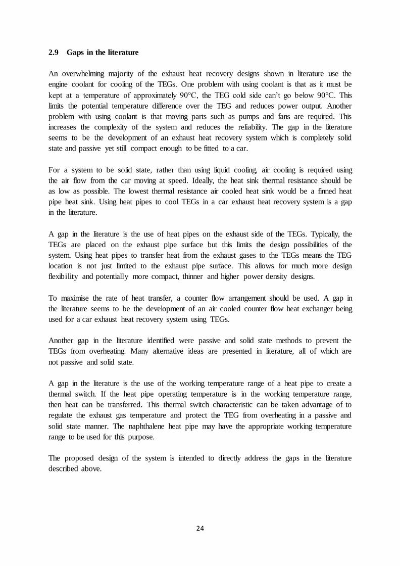
2.9 Gaps in the literature
An overwhelming majority of the exhaust heat recovery designs shown in literature use the
engine coolant for cooling of the TEGs. One problem with using coolant is that as it must be
kept at a temperature of approximately 90°C, the TEG cold side can’t go below 90°C. This
limits the potential temperature difference over the TEG and reduces power output. Another
problem with using coolant is that moving parts such as pumps and fans are required. This
increases the complexity of the system and reduces the reliability. The gap in the literature
seems to be the development of an exhaust heat recovery system which is completely solid
state and passive yet still compact enough to be fitted to a car.
For a system to be solid state, rather than using liquid cooling, air cooling is required using
the air flow from the car moving at speed. Ideally, the heat sink thermal resistance should be
as low as possible. The lowest thermal resistance air cooled heat sink would be a finned heat
pipe heat sink. Using heat pipes to cool TEGs in a car exhaust heat recovery system is a gap
in the literature.
A gap in the literature is the use of heat pipes on the exhaust side of the TEGs. Typically, the
TEGs are placed on the exhaust pipe surface but this limits the design possibilities of the
system. Using heat pipes to transfer heat from the exhaust gases to the TEGs means the TEG
location is not just limited to the exhaust pipe surface. This allows for much more design
flexibility and potentially more compact, thinner and higher power density designs.
To maximise the rate of heat transfer, a counter flow arrangement should be used. A gap in
the literature seems to be the development of an air cooled counter flow heat exchanger being
used for a car exhaust heat recovery system using TEGs.
Another gap in the literature identified were passive and solid state methods to prevent the
TEGs from overheating. Many alternative ideas are presented in literature, all of which are
not passive and solid state.
A gap in the literature is the use of the working temperature range of a heat pipe to create a
thermal switch. If the heat pipe operating temperature is in the working temperature range,
then heat can be transferred. This thermal switch characteristic can be taken advantage of to
regulate the exhaust gas temperature and protect the TEG from overheating in a passive and
solid state manner. The naphthalene heat pipe may have the appropriate working temperature
range to be used for this purpose.
The proposed design of the system is intended to directly address the gaps in the literature
described above.
Page 32
25
Research method, aims and questions
3.1 Research method
The following design has been proposed to address the gaps in the literature. A schematic of
this design can be seen in figure 3.1. The system consists of two ducts. A cool air duct and an
exhaust duct. The flow of exhaust gases comes from the car engine and the flow of cool air
would come from the car moving at speed. For testing purposes a fan would be used to
simulate the air flow from the car moving at speed. The whole system is an air to air heat pipe
heat exchanger in a counter flow arrangement. There are two sections of the system, the
naphthalene heat pipe section and the TEG section.
Figure 3.1: Schematic of the proposed exhaust heat recovery system
The TEG section uses heat pipes to transfer heat to and from the TEGs. When the exhaust
gases pass over the fins inside the exhaust duct, the heat is transferred to the fins then to the
heat pipe. These heat pipes transfer the heat to the hot side of the TEG. This heat passes
through the TEG and small fraction of it is converted into electricity. The remaining heat that
passes through the TEG is removed by the heat pipes on the cold side of the TEG. The heat
pipes transfer this heat to the fins inside the cool air duct and the cool air flowing over the
fins removes this heat. This now heated air is either expelled to the atmosphere or could be
used for car interior heating. The electricity generated by the TEGs would be used to charge a
car battery. This system could potentially replace the car alternator or reduce its load which
would result in a reduction in the fuel consumption of the car. The TEG section of the system
uses no moving parts therefore is completely solid state and passive.
Page 33
26
The purpose of the Naphthalene heat pipe section is to be a pre heat exchanger to prevent the
TEGs and water heat pipes downstream from overheating. Essentially they work as a spoiler /
thermal short circuit / thermal regulator when the exhaust gases are too hot. The TEGs are
designed for a maximum continuous operating temperature of 250°C and the thick walled
water heat pipes can handle 300°C. The Naphthalene heat pipes are designed to operate from
250°C - 450°C. This means that when the exhaust gases are not hot enough to get the heat
pipe into this operating temperature range, these heat pipes will not operate. When the
exhaust gases are very hot, the heat pipe operating temperature will be within this range and
will remove heat. This operating temperature range is convenient because it means that heat
will be removed from the exhaust gases only when required. This will improve the
performance of the system over a wide range of exhaust gas temperatures. Without this
temperature control method, the TEG section would have to be designed for the worst case
scenario which rarely occurs meaning that a majority of the time the system would not be
operating at peak performance. The cooling air for this section is downstream of the TEG
section therefore the air will be relatively warm and will not drag the Naphthalene heat pipes
below their operating temperature range. There are no moving parts or electrically powered
monitoring systems needed therefore this Naphthalene heat pipe pre heat exchanger is a
completely solid state and passive method to prevent the downstream TEGs and heat pipes
from overheating.
As literature on Naphthalene heat pipes are limited, testing the system as shown in figure 3.1
would be too risky because if the Naphthalene heat pipes don’t work as expected, there would
be a risk of damaging the TEG section of the system. Therefore it was decided to test the
Naphthalene section and TEG section separately. The schematics of the two separate systems
are shown in figures 3.2 and 3.3. As the Naphthalene section will not be cooled by the warm
downstream air from the TEG section, an industrial drier will be required to simulate this air
flow. For the TEG section, the fin surface area inside the exhaust duct will need to be reduced
to prevent the heat pipes and TEGs from overheating now that there is no preheat exchanger.
Page 34
27
Figure 3.2: Schematic of the TEG section of the system
Figure 3.3: Schematic of the Naphthalene section of the system
Page 35
28
3.2 Research aims
1) Develop a theoretical model of a car exhaust heat recovery system utilising TEGs and
heat pipes to calculate temperatures and power predictions.
2) Fabricate and test the prototype to validate the theoretical model.
3) Investigate the economic and environmental feasibility of the system.
3.3 Research questions
1) How much power can be generated from a full size system?
2) How much energy can be recovered from a full size system over the life of a car?
3) What are the potential fuel, cost and CO2 savings over the life of the car?
Page 36
29
A review of car waste heat recovery systems
utilising thermoelectric generators and heat
pipes
The work related to this chapter has been peer reviewed and published in Applied thermal
engineering.
The full paper can be obtained via http://dx.doi.org/10.1016/j.applthermaleng.2015.10.081
This work can be cited as: Orr, B, Akbarzadeh, A, Mochizuki, M & Singh, R 2016, 'A review
of car waste heat recovery systems utilising thermoelectric generators and heat pipes',
Applied Thermal Engineering, vol. 101, pp. 490-5.
Page 37
30
Electricity generation from an exhaust heat
recovery system utilising thermoelectric
cells and heat pipes
The work related to this chapter has been peer reviewed and published in Applied thermal
engineering.
The full paper can be obtained via http://dx.doi.org/10.1016/j.applthermaleng.2014.07.056
This work can be cited as: Orr, B, Singh, B, Tan, L & Akbarzadeh, A 2014, 'Electricity
generation from an exhaust heat recovery system utilising thermoelectric cells and heat
pipes', Applied Thermal Engineering, vol. 73, no. 1, pp. 586-95.
Page 38
31
Validating an alternative method to predict
thermoelectric generator performance
The work related to this chapter has been peer reviewed and published in Energy conversion
and management.
The full paper can be obtained via http://dx.doi.org/10.1016/j.enconman.2016.02.074
This work can be cited as: Orr, B, Taglieri, J, Ding, LC & Akbarzadeh, A 2016, 'Validating
an alternative method to predict thermoelectric generator performance', Energy Conversion
and Management, vol. 116, pp. 134-41.
Page 39
32
Experimental testing of a car exhaust heat
recovery system utilising TEGs and heat
pipes
7.1 Journal paper
The work related to this chapter has been peer reviewed and published in SAE-A Vehicle
Technology Engineer.
The full paper can be obtained via http://dx.doi.org/10.7790/vte-j.v2i1.18
This work can be cited as: Orr, B & Akbarzadeh, A 2016, 'Experimental testing of a car
exhaust heat recovery system utilising TEGs and heat pipes', SAE-A Vehicle Technology
Engineer, vol. 2, no. 1.
7.2 Supplementary information
In figure 7.1 below is the Maple code used to predict the temperatures throughout the exhaust
duct and cool air duct. Coloured in red are the input conditions / variables. The initial
temperatures of the ducts, the mass flow rates and specific heats need to be known. The
thermal resistance of a single module also needs to be known. For an 8 module system, there
are 14 unknown temperatures and 14 equations. This coding arranges the 14 equations into a
matrix format and then the matrix equation can be solved. Unknown temperatures Tb to To
are solved in this case.
Page 40
33
Figure 7.1: Maple coding to solve unknown duct temperatures
The potential fuel, fuel cost and CO2 saving can be derived using 2 methods, either the
energy method or power method. In equations 1-6b below, the power method is used to
derive the potential saving equation.
The total rate of energy input from the fuel is equal to the engine mechanical power output
divided by the engine efficiency as described in equation 1.
�̇�𝑡𝑜𝑡 =𝑃𝑒𝑛𝑔
𝜂𝑒𝑛𝑔 (1)
The rate of heat transfer to the exhaust gases is equal to the percentage of fuel energy in the
exhaust multiplied by the total rate of energy input from the fuel as described by equations 2a
and 2b.
�̇�𝑒𝑥ℎ = 𝜂𝑒𝑥ℎ�̇�𝑡𝑜𝑡 (2a)
Page 41
34
=𝜂𝑒𝑥ℎ𝑃𝑒𝑛𝑔
𝜂𝑒𝑛𝑔 (2b)
The heat recovery rate is equal to the heat exchanger effectiveness multiplied by the rate of
heat transfer to the exhaust gases as described by equations 3a and 3b.
�̇�𝑟𝑒𝑐 = 𝜂𝐻𝑋 �̇�𝑒𝑥ℎ (3a)
=𝜂𝐻𝑋𝜂𝑒𝑥ℎ𝑃𝑒𝑛𝑔
𝜂𝑒𝑛𝑔 (3b)
The power generated by the TEGs is equal to the TEG efficiency multiplied by the heat
recovery rate as described by equations 4a and 4b.
𝑃𝑇𝐸𝐺 = 𝜂𝑇𝐸𝐺 �̇�𝑟𝑒𝑐 (4a)
=𝜂𝑇𝐸𝐺 𝜂𝐻𝑋𝜂𝑒𝑥ℎ𝑃𝑒𝑛𝑔
𝜂𝑒𝑛𝑔 (4b)
The mechanical power input to an alternator to produce the same amount of electrical power
as the TEGs is equal to the power generated by the TEGs divided by the alternator efficiency
as described by equations 5a and 5b.
𝑃𝑎𝑙𝑡 =𝑃𝑇𝐸𝐺
𝜂𝑎𝑙𝑡 (5a)
=𝜂𝑇𝐸𝐺 𝜂𝐻𝑋𝜂𝑒𝑥ℎ𝑃𝑒𝑛𝑔
𝜂𝑒𝑛𝑔 𝜂𝑎𝑙𝑡 (5b)
The potential fuel savings is equal to the mechanical power input to an alternator to produce
the same amount of electrical power as the TEGs divided by the engine mechanical power
output as described by equations 6a and 6b.
𝑆𝑎𝑣𝑖𝑛𝑔% =𝑃𝑎𝑙𝑡
𝑃𝑒𝑛𝑔 (6a)
=𝜂𝑇𝐸𝐺 𝜂𝐻𝑋𝜂𝑒𝑥ℎ
𝜂𝑒𝑛𝑔 𝜂𝑎𝑙𝑡 (6b)
To simplify the predicted fuel savings equation, an assumption is made that the fuel
consumption is directly proportional to the power output of the engine. This assumption is
relatively accurate but in reality this is not the case because the engine efficiency changes
with operating conditions.
Page 42
35
To give a sense of how much power a full size system would produce, the previously derived
equation 4b can be used. Using the experimentally determined TEG efficiency and heat
exchanger effectiveness plus the percentage of fuel energy in the exhaust and engine
efficiency stated by Kim et al (2011), the power output of the TEGs can be determined as a
function of engine power output. Table 7.1 shows the potential power output of the TEG
system for a range of engine power outputs.
𝑃𝑇𝐸𝐺 =𝜂𝑇𝐸𝐺 𝜂𝐻𝑋𝜂𝑒𝑥ℎ𝑃𝑒𝑛𝑔
𝜂𝑒𝑛𝑔 (4b)
Table 7.1
Potential TEG system output versus engine power output
Peng (kW) PTEG (W)
20 189
40 378
60 568
80 756
100 945
120 1134
140 1322
160 1511
180 1700
200 1889
To give a sense of how much energy can be recovered from a full size system over the life of
a car and the potential fuel, cost and CO2 savings over the life of a car, equations 7-10 can be
used. Equation 7 can be used to determine the end of life fuel savings, equation 8 can be used
to determine the end of life energy savings, equation 9 can be used to determine the end of
life CO2 reduction and equation 10 can be used to determine the end of life cost savings. All
these equations are a function of the initial fuel economy. The same assumptions as the TEG
power predictions were made. Extra assumptions such as 34.2MJ energy per litre of gasoline,
2.392kg of CO2 per litre of gasoline, 300000km car life expectancy and a gasoline cost of
$1.40 per litre were made. Table 7.2 shows the potential energy, fuel, CO2 and cost
reductions for a range of different initial fuel economies.
𝑇𝑜𝑡𝑎𝑙 𝑓𝑢𝑒𝑙 𝑠𝑎𝑣𝑖𝑛𝑔 (𝐿) = 𝑆𝑎𝑣𝑖𝑛𝑔% × 𝐹𝑢𝑒𝑙 𝑒𝑐𝑜𝑛𝑜𝑚𝑦(𝐿
100𝑘𝑚) × 300000𝑘𝑚 (7)
𝐸𝑛𝑒𝑟𝑔𝑦 𝑠𝑎𝑣𝑖𝑛𝑔 (𝑀𝐽) = 𝑇𝑜𝑡𝑎𝑙 𝑓𝑢𝑒𝑙 𝑠𝑎𝑣𝑖𝑛𝑔(𝐿) × 34.2𝑀𝐽
𝐿 (8)
Page 43
36
𝐶𝑂2 𝑟𝑒𝑑𝑢𝑐𝑡𝑖𝑜𝑛 (𝑘𝑔 𝐶𝑂2) = 𝑇𝑜𝑡𝑎𝑙 𝑓𝑢𝑒𝑙 𝑠𝑎𝑣𝑖𝑛𝑔(𝐿) × 2.392𝑘𝑔 𝐶𝑂2
𝐿 (9)
𝐶𝑜𝑠𝑡 𝑠𝑎𝑣𝑖𝑛𝑔 ($) = 𝑇𝑜𝑡𝑎𝑙 𝑓𝑢𝑒𝑙 𝑠𝑎𝑣𝑖𝑛𝑔(𝐿) × $1.40
𝐿 (10)
Table 7.2
End of life energy, fuel, CO2 and cost savings
Initial fuel
economy
(L/100km)
End of life
energy saving
(MJ)
End of life
fuel savings
(L)
End of life
CO2 reduction
(kg CO2)
End of life
cost savings
($)
5
8071 236 565 331
6
9679 283 678 397
7
11320 331 791 463
8
12928 378 904 529
9
14535 425 1017 595
10
16142 472 1130 661
11
17784 520 1243 727
12
19391 567 1356 793
Page 44
37
Operating characteristics of naphthalene
heat pipes
Abstract
Heat pipes that operate in the medium temperature range (550-700K) are very rarely used in
industry despite the potential demand of use. There is no consensus about suitable working
fluids in this temperature range as research on possible working fluids is limited. One
proposed working fluid is naphthalene. In this chapter, a number of tests have been
undertaken on both an individual naphthalene heat pipe and a naphthalene heat pipe heat
exchanger. Unlike room temperature working fluids, medium temperature working fluids are
solid at ambient temperature therefore they have unusual start up characteristics. Testing has
indicated that these heat pipes start to operate when the temperature of the adiabatic section
reaches approximately 200°C. The tested heat pipes were 8mm in diameter and 278mm long.
The container and mesh material was stainless steel. They were found to have a thermal
resistance of approximately 1°C/W and a maximum rate of heat transfer of 40W. The
orientation was found to have a large effect on the performance of the heat pipes. Compared
to the bottom heat mode orientation, when in a horizontal orientation the heat exchanger
effectiveness more than halved and when in the top heat mode orientation heat exchanger
effectiveness was significantly further reduced.
Page 45
38
Nomenclature 𝐴𝑤
𝐴𝑒𝑣𝑎𝑝 Heat pipe evaporator section surface area [cm2]
𝐸 Heat exchanger effectiveness [%]
𝑔 Acceleration due to gravity [m/s2] ℎ𝑓𝑔 Enthalpy of latent heat [J/kg]
𝐿 𝑒𝑓𝑓 Heat pipe effective length [m]
𝑀 Working fluid figure of merit [W/m2] ∆𝑃𝑐 Capillary pressure [Pa]
∆𝑃𝑔 Gravitational pressure drop [Pa]
∆𝑃𝑙 Liquid pressure drop [Pa]
𝑃ℎ𝑒𝑎𝑡𝑒𝑟 Heater power [W] �̇� Surface heat flux [W/cm2]
�̇� Rate of heat transfer [W]
�̇�𝑐𝑎𝑝 Capillary limit [W]
𝑟𝑝 Wick pore radius [m]
𝑅𝑡ℎ Heat pipe thermal resistance [°C/W] 𝑇𝑐𝑜𝑛𝑑 Heat pipe condenser wall temperature [°C]
𝑇𝑐,𝑖 Heat exchanger cold gas inlet temperature [°C]
𝑇𝑐,𝑜 Heat exchanger cold gas outlet temperature [°C]
𝑇𝑒𝑣𝑎𝑝 Heat pipe evaporator wall temperature [°C]
𝑇ℎ,𝑖 Heat exchanger hot gas inlet temperature [°C]
𝑇ℎ,𝑜 Heat exchanger hot gas outlet temperature [°C]
Greek symbols 𝜅 Wick permeability [m2]
𝜇𝑙 Liquid viscosity [Pa.s]
𝜌𝑙 Liquid density [kg/m3]
𝜎 Surface tension [N/m] 𝜙 Orientation angle [°]
Page 46
39
8.1 Introduction
The typical working fluid used in heat pipes is water. Unfortunately water, like all working
fluids, has limitations of use. One of these limitations is the operating temperature of the heat
pipe. At operating temperatures that are too low, the working fluid will solidify and stop the
heat pipe from working. Therefore for water this will be at 0°C. At operating temperatures
that are too high, the pressure inside the pipe will increase to a level which may rupture the
pipe. Also, the operating temperature can’t exceed the critical point temperature of the
working fluid because phase change is required for the heat transfer. Therefore for water this
will be at 374°C. There are many heat transfer applications which fall outside this range. In
these situations, different working fluids are required. Yang et al (2012) suggested that at low
temperature / cryogenic temperatures (1-200K), working fluids such as helium, argon, neon
and nitrogen are used. In room temperature applications (200-550K), working fluids such as
water, methanol, ethanol, ammonia and acetone are used. In high temperature applications
(>700K), working fluids such as potassium, sodium and silver can be used. All these different
working fluids have varying degrees of performance due to different fluid parameters.
Working fluids for the medium temperature range (550-700K) are not as common. Organic
fluids such as biphenyl have been suggested. Naphthalene is another working fluid which is
suggested by both Yang et al (2012) and Vasiliev (2005).
The reason naphthalene can be used for a medium temperature range heat pipe is because of
the relatively high melting and boiling points. Under atmospheric pressure, naphthalene has a
melting point of 80.2°C and a boiling point of 218°C. Heat pipes using naphthalene will
therefore not work under an operating temperature of 80.2°C. The vapour pressure at high
temperatures is relatively low as compared to water which allows the operating temperature
to go beyond the maximum operating temperature of water. Testing has been undertaken on
naphthalene heat pipes for performance, container compatibilities and performance
degradation over time by Kniess et al (2007), Kimura et al (1994), Mantelli et al (2010),
Vasil’ev et al (1988) and Anderson et al (2007). Naphthalene heat pipes have been proposed
for use in high temperature heat storage applications by Robak et al (2011), Khalifa et al
(2014), Liu (Article in press) and Khalifa et al (2015). Some Chinese companies have
deployed heat exchangers using naphthalene heat pipes in conjunction with other heat pipes
of a different working fluid as shown by TianLi (2009). Liquid metals are used in the high
temperature section, naphthalene is used in the medium temperature section and water in the
low temperature section. The amount of literature on naphthalene heat pipes is quite limited
and very few papers have been published in recent times. Therefore the aim and novelty of
this chapter is to investigate the performance and characteristics of naphthalene heat pipes.
8.2 Testing an individual naphthalene heat pipe
A number of tests were conducted on an individual naphthalene heat pipe. The specifications
of this heat pipe can be seen in table 8.1. The test set up consisted of a high temperature
electrical heater to be placed on the evaporator section of the heat pipe. Fiberglass insulation
was placed over the evaporator section and the adiabatic section. The condenser section was
Page 47
40
exposed to allow for heat dissipation. K type thermocouples were placed on the surface of the
evaporator, adiabatic and condenser sections of the heat pipe. The power supply to the
electrical heater was controlled by a variable DC power source. The schematic of the set up
can be seen in figure 8.1 and the actual set up can be seen in figure 8.2.
Table 8.1
Heat pipe specifications
Diameter
8mm
Length
278mm
Working fluid
Naphthalene
Container material
Stainless steel, 0.5mm wall thickness
Wick
Stainless steel mesh #400 X 2 layers (Note: #400 = 400 square openings across one linear
inch of wick)
Fill ratio 20%
Figure 8.1: Schematic of the individual heat pipe test set up
Page 48
41
Figure 8.2: The test set up for testing an individual heat pipe
Plotted in figure 8.3 are the start-up characteristics of the tested naphthalene heat pipe. Unlike
typical water heat pipes, the naphthalene working fluid is solid when starting from room
temperature. This means that the naphthalene heat pipe will not start transferring heat straight
away whereas water heat pipes will. For this test, everything is initially at room temperature
and then the electric heater is switched on to produce 50W of heat. It can be seen that the
evaporator temperature starts rising straight away. The temperature of the adiabatic section is
constant for a period of time and then starts to rise. The condenser temperature starts to rise
shortly after. During this initial period, the temperature difference over the three sections of
the heat pipe is high, suggesting that the heat pipe is not fully operational. It was thought that
when the operating temperature / adiabatic section temperature of the heat pipe reached
80.2°C, the melting temperature of naphthalene, the heat pipe would start operating as normal
but this was not the case. It can be seen that the temperature of the adiabatic section reaches
more than 400°C before the three temperatures start to converge. Interestingly, it was found
that when the heat input was reduced, the temperature of the adiabatic section could drop as
low as 200°C before the three temperatures started to diverge and the heat pipe stopped
operating.
One possible reason for the heat pipe not working earlier is that the condenser may be
blocked by solid naphthalene. There is no evidence of this because the condenser temperature
surpassed the melting temperature of naphthalene and still did not work properly. A known
problem is caused by the changing density of the naphthalene when changing phase from
liquid to solid. After the heat pipe has stopped being used, the naphthalene will cool to room
temperature and solidify. When the naphthalene solidifies, it will shrink. During the shrinking
process the naphthalene may detach from the wall/wick. The gap between the wall/wick and
Page 49
42
the solid naphthalene will have a large thermal resistance. This may be why a large
temperature is required to initially melt the naphthalene. Fluid migration to the condenser
section is another problem. When the naphthalene reaches the condenser section, it solidifies
and does not return to the evaporator section resulting in dry out of the evaporator section. In
this case the evaporator section temperature would keep rising.
It is known that liquids need an excess temperature over the saturation temperature to initiate
boiling. For water, an excess temperature of 5°C has been observed by Bergman et al (2011).
For naphthalene, the excess temperature may be different. It is unlikely that the excess
temperature required for naphthalene could explain why the temperature of the adiabatic
section needs to reach 400°C before the heat pipe starts to operate. There have been instances
where a heat pipe requires a ‘shock’ to get it working. This can be done either thermally or
mechanically as discussed by Li et al (1991). To shock the heat pipe thermally, a heating
element is used to initiate the boiling. Once the boiling has started, the heater can be turned
off and the heat pipe can operate at lower temperatures and temperature differences.
Mechanical shocking involves vibrating the heat pipe to initiate boiling. Once boiling has
commenced the vibrating can stop. A similar process can be seen when cooling water. Water
in a bottle can be cooled below 0°C and still not freeze. As soon as the bottle is moved,
freezing starts to occur even if the temperature rises to 0°C. For this particular naphthalene
heat pipe test, thermal shock is the likely method which initiated the heat pipe operation. This
theory is supported by the fact that the heat pipe still operated well below the start-up
adiabatic section temperature of approximately 400°C after the start-up occurred.
Hysteresis could be another explanation as to why the heat pipe started to work at an
operating temperature of 400°C but could work as low as 200°C. Hysteresis is the separation
of the melting and boiling temperatures. Possibly in this case the high temperature was
required to initiate the boiling but due to hysteresis the naphthalene would continue boiling
until the operating temperature fell below 200°C.
Page 50
43
Figure 8.3: Start-up characteristics of the naphthalene heat pipe
Using the same set up for the start-up tests, the thermal resistance of the heat pipe was
measured and plotted against the temperature of the adiabatic section. This can be seen in
figure 8.4. The thermal resistance was calculated using equation 11. Due to the unique start-
up characteristics of the naphthalene heat pipe, the thermal resistance at high adiabatic
section temperatures was determined first, and then the power was reduced incrementally to
find the thermal resistance at the lower adiabatic section temperatures. Starting from low
power to high power would get completely different results because the heat pipe would not
be in operation. All tests were conducted within the heat pipe’s maximum rate of heat transfer
so the results would not be skewed at high power input. It can be seen that below an adiabatic
section temperature of approximately 200°C, the thermal resistance rises significantly. This
graph demonstrates that naphthalene heat pipes start to operate at a working temperature /
adiabatic section temperature of approximately 200°C. This compares well with minimum
operating temperatures stated in literature. For example Kniess et al (2007), Kimura et al
(1994) and Mantelli et al (2010) have stated that naphthalene heat pipes start to operate at
250°C.
𝑅𝑡ℎ =𝑇𝑒𝑣𝑎𝑝 −𝑇𝑐𝑜𝑛𝑑
𝑃ℎ𝑒𝑎𝑡𝑒𝑟 (11)
0
100
200
300
400
500
600
00:00 02:00 04:00 06:00 08:00 10:00 12:00 14:00 16:00 18:00
Tem
pe
ratu
re (°
C)
Time (mm:ss)
Condenser section Adiabatic section Evaporator section
Page 51
44
Figure 8.4: Determining the minimum operating temperature of the naphthalene heat pipe
An observation was made during testing that the naphthalene heat pipe does not operate when
an aluminium heat sink is attached to the condenser section and exposed to ambient air /
natural convection. Therefore it was decided to test the heat pipe with the heat sink exposed
to high temperature air. It was thought that having a higher condenser temperature could
possibly increase the operating temperature of the heat pipe into its working range. To do this
some hand held driers were used. The air from the driers was directed at the heat sink. The
hot air supply from these driers was at a constant temperature. These driers are not to be
confused with the heater. The heater is not temperature limited and will keep increasing its
temperature until steady state conditions are met whereas the output air temperature of the
driers is constant. The hot air from the driers was used for cooling, not heating. Two different
driers were tested. The first drier tested was a domestic hair drier. The output air temperature
of this drier was approximately 120°C and maintained the condenser section at the same
temperature. It was found that the heat pipe did not work under these conditions. The
operating temperature of the heat pipe was still not high enough. Therefore it was decided to
use a hand held industrial drier instead. The output air temperature of this drier was
approximately 250°C. It was found that the heat pipe did start working under these conditions
therefore further performance tests were conducted using the industrial drier.
0
5
10
15
20
25
0 100 200 300 400
The
rmal
re
sist
ance
(°C
/W)
Adiabatic section temperature (°C)
Page 52
45
The naphthalene heat pipe was then tested to find its maximum rate of heat transfer and its
thermal resistance. Equation 11 was used to determine the thermal resistance. The schematic
of the set up can be seen in figure 8.5 and the actual test set up can be seen in figure 8.6.
Attached to the heat pipe on the evaporator section was a high temperature rated heater. The
heater was attached to a variable voltage supply. The evaporator section and adiabatic section
of the heat pipe was wrapped in fibreglass wool for insulation. Attached to the condenser
section was the same aluminium heat sink used previously. In this case the heat sink was not
exposed to ambient air but was subjected to hot air from the industrial drier. This drier kept
the condenser section at a relatively constant temperature of approximately 250°C. Using the
variable voltage supply, the power inputs to the heater were made in increments of 10W.
Similarly to previous tests, the heat pipe did not start working until it was at a very high
temperature. If this test was undertaken in the traditional method of starting at a low heater
power input and increasing heater power input incrementally, the results would not be
reflective of the true performance of the heat pipe. Therefore testing started at 60W heater
power input with incremental reductions of 10W. The plotted curve shown in figure 8.7
suggests that this heat pipe has a maximum rate of heat transfer of approximately 40W and a
thermal resistance of approximately 1°C/W under these conditions. Equation 12 determines
the surface heat flux of the heat pipe. With an evaporator length of 50mm and a heat pipe
diameter of 8mm, the surface heat flux when transferring the maximum of 40W was
3.2W/cm2.
�̇� =�̇�
𝐴𝑒𝑣𝑎𝑝 (12)
Figure 8.5: Schematic of the test set up when using the industrial drier
Page 53
46
Figure 8.6: Test set up when using the industrial drier
Figure 8.7: Determining the thermal resistance and maximum rate of heat transfer
0
0.5
1
1.5
2
2.5
0 10 20 30 40 50 60 70
The
rmal
re
sist
ance
(°C
/W)
Rate of heat transfer (W)
Max rate of heat
Rated thermal resistance
Page 54
47
To put the performance of the naphthalene heat pipes into perspective, a copper/water heat
pipe of the same size would have a thermal resistance approaching 0.2°C/W and a maximum
rate of heat transfer closer to 80W (At a lower operating temperature). This is to be expected
because the properties of naphthalene are not as favourable as water for use in heat pipes.
One method to compare working fluids is to look at the figure of merit of the working fluids.
Equation 13 is used to calculate the figure of merit. Figure 8.8 shows the variation of the
figure of merit with changes in temperature as described by Anderson (2005). Despite being
able to handle higher temperatures than water, the peak figure of merit of water is much
higher than the peak figure of merit for naphthalene. The reason for this is over a wide
temperature range, Liu (Article in press) has shown that naphthalene has significantly lower
enthalpy of latent heat, lower surface tension and higher viscosity. The density of
naphthalene is higher but not enough to offset the other drawbacks.
𝑀 =ℎ𝑓𝑔𝜎𝜌𝑙
𝜇𝑙 (13)
Figure 8.8: Variation of the working fluid figure of merit with temperature described by
Anderson (2005)
Page 55
48
8.3 Testing a naphthalene heat pipe heat exchanger
After testing an individual heat pipe, a heat pipe heat exchanger was created using 8 identical
naphthalene heat pipes. A schematic of the system can be seen in figure 8.9. 4 rows of 2
parallel heat pipes were used. The system consists of two ducts, the cool air duct and the
exhaust duct. The high temperature gases were supplied from a car exhaust pipe. The car
used was a 2007 Holden Commodore with a 3.0L V6 gasoline engine. These hot exhaust
gases would go through the exhaust duct with some of the heat extracted by the finned
evaporator section of the heat pipes. This heat would transfer to the finned condenser section
of the heat pipes inside the cool air duct. The cooler air flowing over the fins inside the cool
air duct would extract the heat and this now warmer air is expelled to the atmosphere. The
system is designed to be a counter flow heat exchanger. The final lab set up can be seen in
figure 8.10. In this figure, the system is in a horizontal orientation. The system is entirely
wrapped in fibreglass for insulation. Fibreglass is used because other insulation materials
can’t handle the temperatures present. Attached to the exhaust duct is a flexible metal pipe
which is attached to the car exhaust pipe outlet. At the other end of the exhaust duct an
extractor is attached which directs the exhaust gases out of the building. Attached to the cool
air duct is an industrial drier. The previous tests conducted on the individual heat pipe show
that relatively warm air was required at the condenser section of the heat pipe. The industrial
drier would provide that relatively warm air. K type thermocouples were placed inside both
ducts to plot the temperature profile of the ducts from inlet to outlet.
Figure 8.9: Schematic of the naphthalene heat pipe heat exchanger
Page 56
49
Figure 8.10: Test set up of the naphthalene heat pipe heat exchanger
During testing, the engine was run at 4000RPM under no load. This resulted in the input
temperature of the exhaust duct being approximately 350°C. Initially, to confirm the findings
from the individual heat pipe testing, the industrial drier was not used straight away but a
12V fan was used instead. This fan provided a flow of ambient temperature air through the
cool air duct. In this situation the system was in a horizontal orientation. Similarly to the
individual tests, it was found that the heat pipes did not operate in this situation because the
inlet and outlet temperature of the cool air duct were the same. To see if the heat pipes
worked with no air flow in the cool air duct, the fan was turned off. The air temperature at the
centre of the duct was monitored to see if the heat pipes are operating. It was found that the
heat pipes did not operate under these conditions as the cool air duct remained at ambient
temperature. The orientation was then changed so the heat pipes are in bottom heat mode and
the same two tests were conducted, with a fan and without the fan. Again, when the fan was
used, the temperature of the inlet and outlet were the same so the heat pipes were not
working. Interestingly, when the fan was turned off, the temperature at the centre of the duct
increased to approximately 200°C. This indicates that the heat pipes were working in this
situation unlike the similar test conducted for the individual heat pipe.
Leaving the system in a bottom heat mode orientation, the industrial drier was attached to the
cool air duct. The output air temperature of the industrial drier was approximately 79.5°C.
During this test it was found that the outlet temperature of the cool air duct reached
approximately 259.5°C which indicates that the heat pipes were working. Similarly to the
individual testing, the heat pipes did not operate straight away as the cool air duct outlet did
not reach 259.5°C quickly. At least 15 minutes was required for this temperature to be
reached.
Page 57
50
An interesting observation about this test was that the cool air duct input temperature was
relatively low but the heat pipes still worked. During the individual testing, when a hair drier
with an output temperature of 120°C was used, the heat pipe did not work. The industrial
drier needed to reach 250°C for the heat pipes to start operating but in this case only 79.5°C
was required. One possible reason could be the very low air velocity of the industrial drier.
The hair drier used had a much higher air velocity therefore the thermal resistance and
consequently temperature difference between the air and the condenser section would be
quite low. This means the condenser temperature would be very close to the air temperature.
When the industrial drier is used in this case, the air velocity is very small therefore the
thermal resistance and consequently temperature difference between the air and the
condenser section would be quite high. This means the condenser temperature would be
higher than the air temperature and possibly high enough to operate. Evidence supporting this
theory would be the fact that the heat pipes did work when no fan was used and the duct was
exposed to even cooler ambient air. Another possible reason for the heat pipes working with a
lower than expected cool air duct input temperature would be the fact that vibration was
present during testing. As stated earlier, it is known that some heat pipes need to be triggered
into operation and one of these triggers was mechanical shock. The vibrations coming from
the car exhaust could have helped initiate the boiling inside the heat pipes and acted as the
mechanical shock trigger.
Repeat tests were conducted under these conditions to check the consistency of the results.
The average values and measured variation of the duct inlet and outlet temperature can be
seen in table 8.2. It can be seen that the parameters are relatively consistent. Unfortunately,
due to the much higher mass flow rate in the exhaust duct, the temperature difference over
the exhaust duct is quite small and the variation is a significant percentage of the temperature
difference.
Table 8.2
Repeatability of results
Average value Variation
Cool air duct inlet temperature (°C)
79.5 +/- 0.5
Cool air duct outlet temperature (°C)
259.5 +/- 9.5
Exhaust duct inlet temperature (°C)
346.5 +/- 9.5
Exhaust duct outlet temperature (°C)
326 +/- 12
Testing was undertaken to determine the effect of orientation on the performance of the heat
pipe heat exchanger. With the industrial drier attached, the heat exchanger was tested in a top
heat mode, horizontal heat mode and bottom heat mode orientation. The temperature
throughout the ducts was measured and compared. The plots for these three orientations can
be seen in figure 8.11. The duct locations in figure 8.11 refer to the thermocouple/duct
locations in figure 8.9. It can be seen that the temperature profiles follow what is expected for
Page 58
51
a counter flow heat exchanger. In all three cases the exhaust duct temperature does not drop
significantly because the mass flow rate in the exhaust duct is much higher than the cool air
duct. There is an obvious difference in the cool air duct temperature profiles from the three
different orientations. The temperature difference over the cool air duct in top heat mode is
16°C, in horizontal heat mode is 83°C and in bottom heat mode is 189°C. This indicates that
there is a large change in performance depending on the orientation. In this case, bottom heat
mode is the best, followed by the horizontal heat mode and top heat mode. This is to be
expected because the capillary limit of the heat pipes change with orientation. The capillary
limit occurs when the capillary pressure of the wick equals the total pressure drop inside the
heat pipe. The total pressure drop is the sum of the liquid pressure drop, the vapour pressure
drop and the gravitational pressure drop. The gravitational pressure drop is a function of the
cosine of orientation angle (φ) therefore can reduce the total pressure drop in bottom heat
mode or increase the total pressure drop in top heat mode. Reducing the total pressure drop
increases the capillary limit. The higher rate of heat transfer results in a higher outlet
temperature of the cool air duct in this case. Assuming the vapour pressure loss is negligible,
the capillary limit can be derived from the pressure drop equations as shown in equations
14a-14f where φ=0° for top heat mode, φ=90° for horizontal heat mode and φ=180° for
bottom heat mode.
∆𝑃𝑐 ≥ ∆𝑃𝑙 + ∆𝑃𝑔 (14a)
2𝜎
𝑟𝑝≥
𝑙𝑒𝑓𝑓 �̇�𝜇𝑙
𝐴𝑤 𝜅ℎ𝑓𝑔𝜌𝑙+ 𝜌𝑙𝑔𝑙𝑒𝑓𝑓 cos(𝜙) (14b)
2𝜎
𝑟𝑝− 𝜌𝑙𝑔𝑙𝑒𝑓𝑓 cos(𝜙) ≥
𝑙𝑒𝑓𝑓 �̇�𝜇𝑙
𝐴𝑤 𝜅ℎ𝑓𝑔𝜌𝑙 (14c)
�̇� ≤𝐴𝑤 𝜅ℎ𝑓𝑔𝜌𝑙
𝑙𝑒𝑓𝑓 𝜇𝑙(
2𝜎
𝑟𝑝− 𝜌𝑙𝑔𝑙𝑒𝑓𝑓 cos(𝜙)) (14d)
�̇� ≤𝐴𝑤 𝜅ℎ𝑓𝑔𝜌𝑙 𝜎
𝑙𝑒𝑓𝑓𝜇𝑙(
2
𝑟𝑝−
𝜌𝑙𝑔𝑙𝑒𝑓𝑓 cos(𝜙)
𝜎) (14e)
�̇�𝑐𝑎𝑝 ≤ 𝑀𝐴𝑤 𝜅
𝑙𝑒𝑓𝑓(
2
𝑟𝑝−
𝜌𝑙 𝑔𝑙𝑒𝑓𝑓 cos(𝜙)
𝜎) (14f)
The almost zero heat transfer in top heat mode can be explained by comparing the capillary
pressure in equations 15a-15c and the gravitational pressure loss as shown in equations 16a-
16c. In this case the gravitational pressure loss was higher than the capillary pressure
therefore the heat pipe will not work.
∆𝑃𝑐 =2𝜎
𝑟𝑝 (15a)
∆𝑃𝑐 =2×0.0187
19×10−6 (15b)
Page 59
52
∆𝑃𝑐 = 1968 𝑃𝑎 (15c)
∆𝑃𝑔 = 𝜌𝑙𝑔𝑙𝑒𝑓𝑓 cos(𝜙) (16a)
∆𝑃𝑔 = 1175 × 9.8 × (198 × 10−3) cos(0) (16b)
∆𝑃𝑔 = 2280 𝑃𝑎 (16c)
Figure 8.11: Exhaust and cool air duct temperature profiles in different orientations
The effectiveness of the naphthalene heat pipe heat exchanger can be compared for the three
different orientations. Due to the much smaller mass flow rate in the cool air duct, the
effectiveness in this case is a function of the temperature change in the cool air duct. The
effectiveness can be calculated using equation 17. This information is displayed in figure
8.12. It can be seen that when in bottom heat mode, the heat exchanger works at its best with
an effectiveness of 68%. The effectiveness is more than halved to 28% when changed to a
horizontal heat mode. The top heat mode has a very low effectiveness of 5%. This
information suggests that naphthalene heat pipe performance is sensitive to orientation as all
heat pipes are.
0
50
100
150
200
250
300
350
400
450
1 2 3 4 5
Tem
pe
ratu
re (°
C)
Duct location Top heat mode cool air duct Top heat mode exhaust duct
Horizontal heat mode cool air duct Horizontal heat mode exhaust duct
Bottom heat mode cool air duct Bottom heat mode exhaust duct
Page 60
53
𝐸 =𝑇𝑐,𝑜−𝑇𝑐 ,𝑖
𝑇ℎ ,𝑖−𝑇𝑐 ,𝑖 (17)
Figure 8.12: Comparison of the heat exchanger effectiveness for the three different
orientations
8.4 Conclusion
Testing of an individual naphthalene heat pipe and a naphthalene heat pipe heat exchanger
were undertaken to determine the characteristics and performance of this type of heat pipe.
During the individual heat pipe testing, it was found that these heat pipes have unusual start
up characteristics as they need to be heated up to a very high temperature to initiate operation
but once operating they will continue to do so at lower temperatures. It was determined that
the minimum operating temperature of these heat pipes is approximately 200°C. If ambient
temperature air is used on the heat sink for the condenser, the operating temperature of the
heat pipe will drop below its minimum operating temperature and will fail to operate.
Relatively warm air must be used for cooling of the heat sink. The 8mm diameter, 278mm
long naphthalene heat pipe tested was found to have a thermal resistance of approximately
1°C/W and a maximum rate of heat transfer of 40W. Tests of the naphthalene heat pipe heat
exchanger found that the performance of the heat pipes is very sensitive to their orientation.
The heat exchanger effectiveness for the bottom, horizontal and top heat modes was 68%,
28% and 5% respectively. Results from the heat exchanger test also show that a flow of
ambient temperature air can’t be used for cooling naphthalene heat pipes.
0%
10%
20%
30%
40%
50%
60%
70%
80%
90%
100%
Top heat mode Horizontal heat mode Bottom heat mode
He
at e
xch
ange
r e
ffec
tive
ne
ss
Page 61
54
8.5 Supplementary information
After testing of the individual naphthalene heat pipe and the naphthalene heat pipe heat
exchanger, the prospects of using them for the purpose of exhaust temperature regulation are
not high. There are too many problems which limit their application for this purpose. As
naphthalene is solid at room temperature, their transient response on start-up is poor which
could lead to overheating of the downstream water heat pipes and TEGs during this start-up
period. When the car exhaust temperatures are too high, the required rate of heat transfer of
the naphthalene heat pipes could be in the order of 10s to 100s of kilowatts which would not
be practical in a car. Adding to this problem is much lower maximum rate of heat transfer and
higher thermal resistance compared to a similarly sized water heat pipe. In this case the
required heat exchanger size would be too large. The concept of using the naphthalene heat
pipes as temperature regulators is plausible though but possibly only in situations where low
rates of heat transfer are required (i.e.: low exhaust mass flow rates, etc.).
Page 62
55
Conclusion and future work
9.1 Conclusion
This PhD project involves the study of car exhaust heat recovery systems. The purpose of
these systems is to reduce the fuel consumption of a car by converting some of the waste
exhaust heat into electricity and charging the car battery. Thermoelectric generators and heat
pipes have been identified as potential technology to be implemented for this purpose. The
use of this technology allows for the design of a completely passive and solid state system.
During the period of candidature, a number of testing rigs have been designed, built and then
tested. The first testing rig was an initial prototype exhaust heat recovery system. This system
was intended to be a bench type, proof of concept model. A 50cc Honda petrol engine was
used as the supply of the exhaust gases. This system consisted of eight 40 by 40mm TEGs
and generated a maximum of 6.03W of electricity. The average thermal efficiency of the
TEGs was 1.43% which is approximately 1/15 of the Carnot efficiency.
The second testing rig created was a TEG testing rig. This rig was used to test the validity of
an equation derived which predicts the power output of a TEG as a function of temperature
difference. The gradient of the TEG I-V curve and the gradient of the TEG Voc-ΔT curve
were required to be able to use the equation. The TEG testing rig was used to find these TEG
parameters. The equation was found to be valid except at extreme temperature differences
where the equation over predicts the power output.
The third testing rig created was a second prototype exhaust heat recovery system. This
system was designed to be tested using exhaust gases from a car engine. The design was very
similar to the first prototype but it was built to handle higher heat loads. Smaller fin surface
area in the exhaust duct, thick walled heat pipes, high temperature thermal paste and high
temperature rated TEGs were some of the provisions made to handle the higher temperatures.
A theoretical model of this system was created and the system was tested to validate the
model. The theoretical model was found to be valid but at higher exhaust temperatures, the
model over predicts the power output. The theoretical model assumes a constant thermal
resistance of the heat pipes but when the heat pipes exceed their maximum rate of heat
transfer, their thermal resistance rises significantly. This was the case in the high temperature
tests which is why the model deviated. The parasitic power losses due to the pressure drop in
the exhaust duct was in all cases a fraction of the electrical power generated. Orientation
testing has found that the system works best in bottom heat mode followed by horizontal heat
mode and top heat mode. The maximum electrical power produced during testing was 38W at
a thermal efficiency of 2.46%. Similarly to the first prototype, the system consisted of 8
TEGs but in this case a larger size of 62 by 62mm. If a full size system (more TEGs, heat
pipes, etc.) was fitted to a car with the same TEG efficiency and heat exchanger
effectiveness, the predicted fuel consumption, fuel cost and CO2 emission reduction would be
1.57%.
Page 63
56
The fourth testing rig created was a naphthalene heat pipe heat exchanger. Before testing on
heat exchanger started, testing on an individual heat pipe was undertaken. It was found that
the minimum operating temperature of this heat pipes was approximately 200°C. This
temperature is ideal for the proposed pre heat exchanger set up. It was found that these heat
pipes have unusual start up characteristics. During start-up, the operating temperature would
have to exceed the minimum operating temperature before it starts to operate. The heat pipes
did not operate when cooled by ambient temperature air. The heat pipe was 8mm in diameter
and 278.5mm long and was found to have a thermal resistance of approximately 1°C/W and a
maximum rate of heat transfer of 40W. The naphthalene heat pipe heat exchanger was tested
using car exhaust gas. The heat exchanger was found to be sensitive to orientation with the
heat exchanger effectiveness ranging from 68% in bottom heat mode to 5% in top heat mode.
A naphthalene heat pipe pre heat exchanger may not be viable for a full size car due to the
large heat exchanger size required. To protect the downstream TEGs and water heat pipes,
heat transfer rates in the order of 10s to 100s of kilowatts may be required which would make
the system too large for fitment to a car. This passive method of temperature regulation
proposed may be viable for situations with low rates of heat transfer.
All of these experiments conducted throughout the candidature have met the research aims of
this project and answered the research questions. Heat pipes and TEGs have been shown to
have a potential application in car exhaust heat recovery systems.
9.2 Future work
From the prototype 1 to prototype 2 exhaust heat recovery system, the power density
improved nearly 6-7 times but further power density improvements are required. To be
viable, the volume of the system can’t increase but the power output must be a sizable
percentage of the output of the car alternator. A typical maximum power output of a car
alternator is 1-2kW. Maximum power is rarely needed so if the exhaust heat recovery system
produces the car’s power requirements most of the time, then this may be viable. Different
thermoelectric materials that can handle higher temperatures than the standard bismuth
telluride could be tested with the TEG testing rig. The ability to use higher temperatures
could potentially improve the power density of the system in two ways. Firstly the power
output of the TEGs would increase and secondly the naphthalene pre heat exchanger may not
be required. Instead, the naphthalene heat pipes could be used to transfer the heat to the high
temperature TEGs. As the performance of the naphthalene heat pipes do not compare well
with water heat pipes (albeit in different temperature ranges), this may lead to other problems
which can be investigated such as “how to transfer heat to the TEGs at a high temperature”.
Although electrical power has been generated by the prototype systems, they were not
connected to the car electrical system. Further research into how to connect the power output
to the car electrical system should be conducted. Rather than doing laboratory tests on the
exhaust heat recovery system, the system should be fitted to a car and field tested to find the
real world power outputs and fuel economy benefits.
Page 64
57
Bibliography
Anderson, WG 2005, 'Evaluation of heat pipes in the temperature range of 450 to 700 K',
paper presented to AIP Conference Proceedings. Anderson, WG, Hartenstine, JR, Sarraf, DB & Tarau, C 2007, 'Intermediate temperature
fluids for heat pipes and loop heat pipes', paper presented to Proceedings of the international energy conversion engineering conference, St. Louis, MO.
Arias, DA, Shedd, TA & Jester, RK 2006, 'Theoretical Analysis of Waste Heat Recovery
from an Internal Combustion Engine in a Hybrid Vehicle', <http://dx.doi.org/10.4271/2006-01-1605>.
Baatar, N & Kim, S 2011, 'A Thermoelectric Generator Replacing Radiator for Internal Combustion Engine Vehicles', TELKOMNIKA, vol. 9, no. 3, pp. 523-30.
Bai, M, Tan, G, Deng, Y, Wang, W & Yan, H 2014, 'Cold-end Temperature Control Method
for the Engine Exhaust Heat Thermoelectric Module', <http://dx.doi.org/10.4271/2014-01-2343>.
Bass, JC, Elsner, NB & Leavitt, FA 1994, Performance of the 1kW Thermoelectric Generator for Diesel Engines, viewed 03/04/2013 <http://www.hi-z.com/papers/ICT%201994%20-
%20Performance%20of%201%20kW%20TE%20Gen.pdf>. Bass, JC, Kushch, AS & Elsner, NB 2001, Thermoelectric Generator (TEG) for Heavy Diesel
Trucks, viewed 03/04/2013 <http://www.hi-z.com/papers/ICT%202001%20Beijing(China).pdf>.
Bergman, TL, Incropera, FP & Lavine, AS 2011, Fundamentals of heat and mass transfer,
John Wiley & Sons. Bitschi, A 2009, 'Modelling of thermoelectric devices for electric power generation'.
Brito, F, Martins, J, Goncalves, LM & Sousa, R 2012, 'Temperature Controlled Exhaust Heat Thermoelectric Generation', SAE Int. J. Passeng. Cars - Electron. Electr. Syst., vol. 5, no. 2, pp. 561-71.
Brito, FP, Alves, A, Pires, JM, Martins, LB, Martins, J, Oliveira, J, Teixeira, J, Goncalves, LM & Hall, MJ 2015, 'Analysis of a Temperature-Controlled Exhaust Thermoelectric
Generator During a Driving Cycle', Journal of Electronic Materials, pp. 1-25. Brito, FP, Goncalves, LM, Martins, J, Antunes, N & Sousa, D 2013, 'Influence of Heat Pipe
Operating Temperature on Exhaust Heat Thermoelectric Generation', SAE Int. J.
Passeng. Cars - Mech. Syst., vol. 6, no. 2. Brito, FP, Martins, J, Hançer, E, Antunes, N & Gonçalves, LM 2015, 'Thermoelectric
Exhaust Heat Recovery with Heat Pipe-Based Thermal Control', Journal of Electronic Materials.
Chaudhry, HN, Hughes, BR & Ghani, SA 2012, 'A review of heat pipe systems for heat
recovery and renewable energy applications', Renewable and Sustainable Energy Reviews, vol. 16, no. 4, pp. 2249-59.
Chen, M & Gao, X 2014, 'Theoretical, experimental and numerical diagnose of critical power point of thermoelectric generators', Energy, vol. 78, pp. 364-72.
Crane, DT 2009, 'Design to maximize performance of a thermoelectric power generator with
a dynamic thermal power source', Journal of energy resources technology, vol. 131. Dai, D, Zhou, Y & Liu, J 2011, 'Liquid metal based thermoelectric generation system for
waste heat recovery', Renewable Energy, vol. 36, no. 12, pp. 3530-6. Date, A, Date, A, Dixon, C & Akbarzadeh, A 2014, 'Progress of thermoelectric power
generation systems: Prospect for small to medium scale power generation', Renewable
and Sustainable Energy Reviews, vol. 33, pp. 371-81.
Page 65
58
Deng, Y & Liu, J 2010, 'A liquid metal cooling system for the thermal management of high power LEDs', International Communications in Heat and Mass Transfer, vol. 37, no.
7, pp. 788-91. Djafar, Z, Putra, N & Koestoer, RA 2013, The utilization of heat pipe on cold surface of
thermoelectric with low-temperature waste heat, <http://www.scopus.com/inward/record.url?eid=2-s2.0-84874899901&partnerID=40&md5=088d99588963ee9c7edb0cd423458557>.
Espinosa, N, Lazard, M, Aixala, L & Scherrer, H 2010, 'Modeling a thermoelectric generator applied to diesel automotive heat recovery', Journal of Electronic Materials, vol. 39,
no. 9, pp. 1446-55. Ferrari, C, Melino, F, Pinelli, M, Spina, PR & Venturini, M 2014, 'Overview and status of
thermophotovoltaic systems'.
Fu, J, Tang, Y, Chen, W, Ma, Y & Zhu, Z 2015, 'Research on engine exhaust energy recovery by a heat pipe exchanger with a semiconductor thermoelectric generator',
Open Mechanical Engineering Journal, vol. 9, no. 1, pp. 130-40. Goldsmid, H 2014, 'Bismuth Telluride and Its Alloys as Materials for Thermoelectric
Generation', Materials, vol. 7, no. 4, pp. 2577-92.
Goncalves, LM, Martins, J, Antunes, J, Rocha, R & Brito, FP 2010, 'Heat-pipe assisted thermoelectric generators for exhaust gas applications', paper presented to ASME
2010 International Mechanical Engineering Congress & Exposition. Gou, X, Ping, H, Ou, Q, Xiao, H & Qing, S 'A novel thermoelectric generation system with
thermal switch', Applied Energy.
Han, HS, Kim, YH, Kim, SY, Um, S & Hyun, JM 2010, 'Performance measurement and analysis of a thermoelectric power generator', paper presented to 2010 12th IEEE
Intersociety Conference on Thermal and Thermomechanical Phenomena in Electronic Systems, ITherm 2010.
Han, T, Gong, G, Liu, Z & Zhang, L 2014, 'Optimum design and experimental study of a
thermoelectric ventilator', Applied Thermal Engineering, vol. 67, no. 1-2, pp. 529-39. Hassan, KS 2012, 'Heat exchanger design and development for automotive exhaust waste
heat recovery using thermoelectric devices', M.S. thesis, The University of Texas at El Paso.
Hendricks, TJ, Karri, NK, Hogan, TP & Cauchy, CJ 2013, 'New perspectives in
thermoelectric energy recovery system design optimization', Journal of Electronic Materials, vol. 42, no. 7, pp. 1725-36.
Hertwich, EG & Peters, GP 2009, 'Carbon Footprint of Nations: A Global, Trade-Linked Analysis', Environmental Science & Technology, vol. 43, no. 16, pp. 6414-20.
Hsiao, YY, Chang, WC & Chen, SL 2010, 'A mathematic model of thermoelectric module
with applications on waste heat recovery from automobile engine', Energy, vol. 35, no. 3, pp. 1447-54.
Hsu, CT, Huang, GY, Chu, HS, Yu, B & Yao, DJ 2011, 'Experiments and simulations on low-temperature waste heat harvesting system by thermoelectric power generators', Applied Energy, vol. 88, no. 4, pp. 1291-7.
Huang, BJ, Hsu, PC, Tsai, RJ & Hussain, MM 2015, 'A thermoelectric generator using loop heat pipe and design match for maximum-power generation', Applied Thermal
Engineering, vol. 91, pp. 1082-91. Hung, TC, Shai, TY & Wang, SK 1997, 'A review of organic rankine cycles (ORCs) for the
recovery of low-grade waste heat', Energy, vol. 22, no. 7, pp. 661-7.
Hussain, QE, Brigham, DR & Maranville, CW 2009, 'Thermoelectric Exhaust Heat Recovery for Hybrid Vehicles', SAE Int. J. Engines, vol. 2, no. 1, pp. 1132-42.
Jang, JC, Chi, RG, Rhi, SH, Lee, KB, Hwang, HC, Lee, JS & Lee, WH 2015, 'Heat Pipe-
Page 66
59
Assisted Thermoelectric Power Generation Technology for Waste Heat Recovery', Journal of Electronic Materials.
Jeong, YS & Bang, IC 2016, 'Hybrid heat pipe based passive cooling device for spent nuclear fuel dry storage cask', Applied Thermal Engineering, vol. 96, pp. 277-85.
Kakhramanov, KS, Mazur, VA, Alieva, AP & Akhmedli, GT 1984, 'NEW CONNECTOR MATERIALS FOR SOLAR THERMOELECTRIC CELLS BASED ON BISMUTH AND ANTIMONY CHALCOGENIDES', Applied Solar Energy (English translation
of Geliotekhnika), vol. 20, no. 3, pp. 9-11. Karami, N & Moubayed, N 2014, 'New modeling approach and validation of a thermoelectric
generator', paper presented to IEEE International Symposium on Industrial Electronics.
Karri, MA, Thacher, EF & Helenbrook, BT 2011, 'Exhaust energy conversion by
thermoelectric generator: Two case studies', Energy Conversion and Management, vol. 52, no. 3, pp. 1596-611.
Khalifa, A, Tan, L, Date, A & Akbarzadeh, A 2014, 'A numerical and experimental study of solidification around axially finned heat pipes for high temperature latent heat thermal energy storage units', Applied Thermal Engineering, vol. 70, no. 1, pp. 609-19.
Khalifa, A, Tan, L, Date, A & Akbarzadeh, A 2015, 'Performance of suspended finned heat pipes in high-temperature latent heat thermal energy storage', Applied Thermal
Engineering, vol. 81, pp. 242-52. Kim, S, Park, S, Kim, S & Rhi, SH 2011, 'A thermoelectric generator using engine coolant
for light-duty internal combustion Engine-Powered Vehicles', Journal of Electronic
Materials, vol. 40, no. 5, pp. 812-6. Kim, SH, Rhi, SH, Jang, JC & Cha, KI 2012, 'Multi-layer thermoelectric power generation
system using hot exhaust gas for future hybrid vehicles', Advanced Science Letters, vol. 6, pp. 150-8.
Kim, SK, Won, BC, Rhi, SH, Kim, SH, Yoo, JH & Jang, JC 2011, 'Thermoelectric power
generation system for future hybrid vehicles using hot exhaust gas', Journal of Electronic Materials, vol. 40, no. 5, pp. 778-83.
Kimura, Y, Kawabata, K & Sotani, J 1994, 'Life testing of carbon steel/naphthalene and carbon steel/biphenyl heat pipes', paper presented to 4th international heat pipe symposium, University of Tsukuba.
Kniess, CT, Mantelli, MBH, Cunha, A, Martins, GJM, Nuernberg, GV, Angelo, W, Nuernberg, C & Coelho, CE 2007, 'Experimental study of mercury and naphthalene
thermosyphons', paper presented to 14th International Heat pipe Conference, Florianopolis, Brazil.
Koshigoe, M, Shiota, I & Nishida, IA 1999, 'Expansion of utilizing temperature range of
Bi2Te3/PbTe by FGM forming', Materials Science Forum, vol. 308-311, pp. 693-8. LaGrandeur, J, Crane, D, Hung, S, Mazar, B & Eder, A 2006, 'Automotive waste heat
conversion to electric power using skutterudite, TAGS, PbTe and BiTe', paper presented to International Conference on Thermoelectrics.
Lee, H 2011, 'Thermoelectrics', Thermal Design: Heat Sinks, Thermoelectrics, Heat Pipes,
Compact Heat Exchangers, and Solar Cells, pp. 100-79. Lee, J, Ohn, H, Choi, J-Y, Kim, SJ & Min, B 2011, 'Development of Effective Exhaust Gas
Heat Recovery System for a Hybrid Electric Vehicle', <http://dx.doi.org/10.4271/2011-01-1171>.
Li, H, Akbarzadeh, A & Johnson, P 1991, 'The thermal characteristics of a closed two-phase
thermosyphon at low temperature difference', Heat Recovery Systems and CHP, vol. 11, no. 6, pp. 533-40.
Liang, G, Zhou, J & Huang, X 2011, 'Analytical model of parallel thermoelectric generator',
Page 67
60
Applied Energy, vol. 88, no. 12, pp. 5193-9. Liang, X, Sun, X, Tian, H, Shu, G, Wang, Y & Wang, X 2014, 'Comparison and parameter
optimization of a two-stage thermoelectric generator using high temperature exhaust of internal combustion engine', Applied Energy, vol. 130, pp. 190-9.
Liu, C & Li, WZ 2015, 'An Experimental Study of a Two-stage Thermoelectric Generator Using Heat Pipe in Vehicle Exhaust', Distributed Generation & Alternative Energy Journal, vol. 30, no. 1, pp. 15-37.
Liu, Z-h, Zheng, B-c, Wang, Q & Li, S-S 'Study on the thermal storage performance of a gravity-assisted heat-pipe thermal storage unit with granular high-temperature phase-
change materials', Energy, no. 0. Love, ND, Szybist, JP & Sluder, CS 2012, 'Effect of heat exchanger material and fouling on
thermoelectric exhaust heat recovery', Applied Energy, vol. 89, no. 1, pp. 322-8.
Mantelli, MBH, Ângelo, WB & Borges, T 2010, 'Performance of naphthalene thermosyphons with non-condensable gases - Theoretical study and comparison with data',
International Journal of Heat and Mass Transfer, vol. 53, no. 17-18, pp. 3414-28. Martins, J, Goncalves, LM, Antunes, J & Brito, FP 2011, 'Thermoelectric Exhaust Energy
Recovery with Temperature Control through Heat Pipes',
<http://dx.doi.org/10.4271/2011-01-0315>. Mori, M, Yamagami, T, Oda, N, Hattori, M, Sorazawa, M & Haraguchi, T 2009, 'Current
Possibilities of Thermoelectric Technology Relative to Fuel Economy', <http://dx.doi.org/10.4271/2009-01-0170>.
Mori, M, Yamagami, T, Sorazawa, M, Miyabe, T, Takahashi, S & Haraguchi, T 2011,
'Simulation of Fuel Economy Effectiveness of Exhaust Heat Recovery System Using Thermoelectric Generator in a Series Hybrid', SAE Int. J. Mater. Manuf., vol. 4, no. 1,
pp. 1268-76. Remeli, MF, Date, A, Orr, B, Ding, LC, Singh, B, Affandi, NDN & Akbarzadeh, A 2016,
'Experimental investigation of combined heat recovery and power generation using a
heat pipe assisted thermoelectric generator system', Energy Conversion and Management, vol. 111, pp. 147-57.
Remeli, MF, Tan, L, Date, A, Singh, B & Akbarzadeh, A 2015, 'Simultaneous power generation and heat recovery using a heat pipe assisted thermoelectric generator system', Energy Conversion and Management, vol. 91, no. 0, pp. 110-9.
Ringler, J, Seifert, M, Guyotot, V & Hübner, W 2009, 'Rankine Cycle for Waste Heat Recovery of IC Engines', SAE Int. J. Engines, vol. 2, no. 1, pp. 67-76.
Robak, CW, Bergman, TL & Faghri, A 2011, 'Economic evaluation of latent heat thermal energy storage using embedded thermosyphons for concentrating solar power applications', Solar Energy, vol. 85, no. 10, pp. 2461-73.
Rowe, DM & Min, G 1998, 'Evaluation of thermoelectric modules for power generation', Journal of Power Sources, vol. 73, no. 2, pp. 193-8.
Rowe, DM, Smith, J, Thomas, G & Min, G 2011, 'Weight penalty incurred in thermoelectric recovery of automobile exhaust heat', Journal of Electronic Materials, vol. 40, no. 5, pp. 784-8.
Saidur, R, Rezaei, M, Muzammil, WK, Hassan, MH, Paria, S & Hasanuzzaman, M 2012, 'Technologies to recover exhaust heat from internal combustion engines', Renewable
and Sustainable Energy Reviews, vol. 16, no. 8, pp. 5649-59. Saqr, KM, Mansour, MK & Musa, MN 2008, 'Thermal design of automobile exhaust based
thermoelectric generators: Objectives and challenges', International Journal of
Automotive Technology, vol. 9, no. 2, pp. 155-60. Schlitz, D & Singhal, V 2008, 'An electro-aerodynamic solid-state fan and cooling system',
paper presented to Annual IEEE Semiconductor Thermal Measurement and
Page 68
61
Management Symposium. Segev, G, Kribus, A & Rosenwaks, Y 2013, 'High performance isothermal photo-thermionic
solar converters', Solar Energy Materials and Solar Cells, vol. 113, pp. 114-23. Srimuang, W & Amatachaya, P 2012, 'A review of the applications of heat pipe heat
exchangers for heat recovery', Renewable and Sustainable Energy Reviews, vol. 16, no. 6, pp. 4303-15.
Stobart, R & Milner, D 2009, 'The Potential for Thermo-Electric Regeneration of Energy in
Vehicles', <http://dx.doi.org/10.4271/2009-01-1333>. Suzuki, RO & Tanaka, D 2003, 'Mathematical simulation of thermoelectric power generation
with the multi-panels', Journal of Power Sources, vol. 122, no. 2, pp. 201-9. Tian, H, Sun, X, Jia, Q, Liang, X, Shu, G & Wang, X 2015, 'Comparison and parameter
optimization of a segmented thermoelectric generator by using the high temperature
exhaust of a diesel engine', Energy, vol. 84, pp. 121-30. TianLi 2009, High-temperature Heat Pipe Exchanger, viewed 12/09/2016
<http://en.kytl.com/technology/tech.aspx?ID=6&>. Vasil'ev, LL, Volokhov, GM, Gigevich, AS & Rabetskii, MI 1988, 'Heat pipes based on
naphthalene', Journal of Engineering Physics, vol. 54, no. 6, pp. 623-6.
Vasiliev, LL 2005, 'Heat pipes in modern heat exchangers', Applied Thermal Engineering, vol. 25, no. 1, pp. 1-19.
Wallin, P 2012, Heat Pipe, selection of working fluid, viewed 03/04/2013 <http://www.ht.energy.lth.se/fileadmin/ht/Kurser/MVK160/2012/Per_Wallin.pdf>.
Wang, X, Li, B, Yan, Y, Liu, S & Li, J 2016, 'A study on heat transfer enhancement in the
radial direction of gas flow for thermoelectric power generation', Applied Thermal Engineering, vol. 102, pp. 176-83.
Yang, F, Yuan, X & Lin, G 2003, 'Waste heat recovery using heat pipe heat exchanger for heating automobile using exhaust gas', Applied Thermal Engineering, vol. 23, no. 3, pp. 367-72.
Yang, X, Yan, YY & Mullen, D 2012, 'Recent developments of lightweight, high performance heat pipes', Applied Thermal Engineering, vol. 33-34, no. 1, pp. 1-14.
Zhang, G, Fan, L, Niu, Z, Jiao, K, Diao, H, Du, Q & Shu, G 2015, 'A comprehensive design method for segmented thermoelectric generator', Energy Conversion and Management, vol. 106, pp. 510-9.
Zhang, G, Jiao, K, Niu, Z, Diao, H, Du, Q, Tian, H & Shu, G 2016, 'Power and efficiency factors for comprehensive evaluation of thermoelectric generator materials',
International Journal of Heat and Mass Transfer, vol. 93, pp. 1034-7. Zheng, XF, Liu, CX, Yan, YY & Wang, Q 2014, 'A review of thermoelectrics research -
Recent developments and potentials for sustainable and renewable energy
applications', Renewable and Sustainable Energy Reviews, vol. 32, pp. 486-503.