POWER QUALITY Energy Efficiency Reference VOLTAGE SAG CURRENT SWELL Time Voltage Current LINE-NEUT VOLTAGE SAG 200V 100A 30.0A AMPS 0A 125V 105V 0V 20.0v/div vertical 2 sec/div horizontal 10.0A/div vertical 2 sec/div horizontal LINE AMPS CURRENT SURGE Time
Transcript
POWERQUALITY
Energy Effi ciency Reference VOLTAGE SAG
CURRENT SWELL
Time
Volta
geCu
rren
t
LINE-NEUT VOLTAGE SAG
200V
100A
30.0A
AMPS
0A
125V
105V
0V20.0v/div vertical 2 sec/div horizontal
10.0A/div vertical 2 sec/div horizontalLINE AMPS CURRENT SURGE
Time
DISCLAIMER: Neither CEA Technologies Inc. (CEATI), the authors, nor any of the organizations providing funding support for this work (including any persons acting on the behalf of the aforementioned) assume any liability or responsibility for any damages arising or resulting from the use of any information, equipment, product, method or any other process whatsoever disclosed or contained in this guide.
Th e use of certifi ed practitioners for the application of the informa-tion contained herein is strongly recommended.
Th is guide was prepared by Energy @ Work for the CEA Tech-nologies Inc. (CEATI) Customer Energy Solutions Interest Group (CESIG) with the sponsorship of the following utility consortium participants:
Appreciation to Ontario Hydro, Ontario Power Generation and others who have contributed material that has been used in preparing this guide.
TABLE OF CONTENTS
Chapter Page
1 The Scope of Power Quality 9
1.1 Defi nition of Power Quality 9
1.2 Voltage 9
1.3 Why Knowledge of Power Quality is Important 13
1.4 Major Factors Contributing to Power Quality Issues 14
1.5 Supply vs. End Use Issues 15
1.6 Countering the Top 5 PQ Myths 16
1.7 Financial and Life Cycle Costs 18
2 Understanding Power Quality Concepts 23
2.1 The Electrical Distribution System 23
2.2 Basic Power Quality Concepts 28
3 Power Quality Problems 31
3.1 How Power Quality Problems Develop 31
3.2 Power Quality Disturbances 33
3.3 Load Sensitivity: Electrical Loads that are Affected by Poor Power Quality 34
3.4 Types and Sources of Power Quality Problems 37
Power Line Disturbances Summary 39
3.5 Relative Frequency of Occurrence 60
3.6 Related Topics 63
3.7 Three Power Quality Case Studies 64
4 Solving and Mitigating Electrical Power Problems 71
4.1 Identifying the Root Cause and Assessing Symptoms 71
4.2 Improving Site Conditions 72
4.3 Troubleshooting and Predictive Tips 92
5 Where to Go For Help 97
Web Resources 97
CSA Relevant Standards 98
CEATI Reference Documents 100
FORWARD
Power Quality Guide FormatPower quality has become the term used to describe a wide range of electrical power measurement and operational issues. Organizations have become concerned with the importance of power quality because of potential safety, operational and economic impacts.
Power quality is also a complex subject requiring specifi c terminology in order to properly describe situations and issues. Understanding and solving problems becomes possible with the correct information and interpretation.
Th is Power Quality Reference Guide is written to be a useful and practical guide to assist end-use customers and is structured in the following sections:
Section 1: Scope of Power Quality
Provides an understanding that will help to de-mystify power quality issues
Section 2: Understanding Power Quality Concepts
Defi nes power quality, and provides concepts and case study examples
Section 3: Power Quality Problems
Helps to understand how power quality problems develop
Section 4: Solving and Mitigating Electrical Power Problems
Suggestions and advice on potential power quality issues
Section 5: Where to go for Help
Power quality issues are often addressed reactively. Planned maintenance is more predictable and cost eff ective than unplanned, or reactive, maintenance if the right information is available. Power quality problems often go unnoticed, but can be avoided with regular planned maintenance and the right mitigating technologies.
Prevention is becoming more accepted as companies, particularly those with sensitive equipment, are recognizing that metering, monitoring and management is an eff ective strategy to avoid unpleasant surprises. Metering technology has also improved and become cost eff ective in understanding issues and avoiding problems.
Selecting the proper solution is best achieved by asking the right question up front. In the fi eld of power quality, that question might best be addressed as:
“What level of power quality is required for my electrical system to operate in a satisfactory manner, given proper care and maintenance?”
NOTE: It is strongly recommended that individuals or compa-nies undertaking comprehensive power quality projects secure the services of a professional specialist qualifi ed in power quality in order to understand and maximize the available benefi ts. Project managers on power quality projects often undervalue the importance of obtaining the cor-rect data, analysis and up-front engineering that is necessary to
thoroughly understand the root cause of the problems. Knowing the problem and reviewing options will help secure the best solution for the maximum return on investment (ROI).
9
1 The Scope of Power Quality
1 THE SCOPE OF POWER QUALITY
1.1 Defi nition of Power Quality Th e Institute of Electrical and Electronic Engineers (IEEE) defi nes power quality as:
“Th e concept of powering and grounding electronic equipment in a manner that is suitable to the operation of that equipment and compatible with the premise wiring system and other connected equipment.” 1
Making sure that power and equipment are suitable for each other also means that there must be compatibility between the electrical system and the equipment it powers. Th ere should also be compatibility between devices that share the electrical distribution space. Th is concept is called Electromagnetic Compatibility (“EMC”) and is defi ned as:
“the ability of an equipment or system to function satisfactorily in its electromagnetic environment without introducing intolerable electromagnetic disturbances to anything in that environment.” 2
Th e best measure of power quality is the ability of electrical equipment to operate in a satisfactory manner, given proper care and maintenance and without adversely aff ecting the operation of other electrical equipment connected to the system.
1.2 VoltageTh e voltage produced by utility electricity generators has a sinu-soidal waveform with a frequency of 60 Hz in North America
1 - IEEE-Std 1100-1999, IEEE Recommended Practice for Powering and Grounding Electronic Equipment, New York, IEEE 1999.2 - A defi nition from the IEC at http://www.iec.ch/zone/emc/whatis.htm.
10
1 The Scope of Power Quality
and 50 Hz in many other parts of the world. Th is frequency is called the fundamental frequency.
Any variation to the voltage waveform, in magnitude or in frequency, is called a power line deviation. However, not all power line deviations result in disturbances that can cause problems with the operation of electrical equipment.
1.2.1 Voltage LimitsExcessive or reduced voltage can cause wear or damage to an electrical device. In order to provide standardization, recom-mended voltage variation limits at service entrance points are specifi ed by the electrical distributor or local utility. An example of typical voltage limits is shown in the table below.
11
1 The Scope of Power Quality
Rated voltage (V)* Voltage limits at point of delivery
In addition to system limits, Electrical Codes specify voltage drop constraints; for instance:
(1) Th e voltage drop in an installation shall:
Be based upon the calculated demand load of the • feeder or branch circuit.
Not exceed 5% from the supply side of the consumer’s • service (or equivalent) to the point of utilization.
Not exceed 3% in a feeder or branch circuit.•
(2) Th e demand load on a branch circuit shall be the conected load, if known, otherwise 80% of the rating of the overload or over-current devices protecting the branch circuit, whichever is smaller.3
3 - Check with your local Authority Having Jurisdiction for rules in your area.
12
1 The Scope of Power Quality
For voltages between 1000 V and 50 000 V, the maximum al-lowable variation is typically ±6% at the service entrance. Th ere are no comparable limits for the utilization point. Th ese voltage ranges exclude fault and temporary heavy load conditions. An example of a temporary heavy load condition is the startup of a motor. Since motors draw more current when they start than when they are running at their operating speed, a voltage sag may be produced during the initial startup.
VOLTAGE SAG
CURRENT SWELL
Time
Volta
geCu
rren
t
LINE-NEUT VOLTAGE SAG
200V
100A
30.0A
AMPS
0A
125V
105V
0V20.0v/div vertical 2 sec/div horizontal
10.0A/div vertical 2 sec/div horizontalLINE AMPS CURRENT SURGE
Time
Figure 2: RMS Voltage and Current Produced when Starting a Motor
(Reproduced with Permission of Basic Measuring Instruments, from “Handbook of Power Signatures”, A. McEachern, 1988)
13
1 The Scope of Power Quality
It is not technically feasible for a utility to deliver power that is free of disturbances at all times. If a disturbance-free voltage waveform is required for the proper operation of an electrical product, mitigation techniques should be employed at the point of utilization.
1.3 Why Knowledge of Power Quality is Important
Owning or managing a concentration of electronic, control or life-safety devices requires a familiarity with the importance of electrical power quality.
Power quality diffi culties can produce signifi cant problems in situations that include:
Important business applications (banking, inventory • control, process control)
Essential public services (paramedics, hospitals, police, • air traffi c control)
Power quality problems in an electrical system can also quite frequently be indicative of safety issues that may need immedi-ate corrective action. Th is is especially true in the case of wiring, grounding and bonding errors.
Your electrical load should be designed to be compatible with your electrical system. Performance measures and operating guidelines for electrical equipment compatibility are available from professional standards, regulatory agency policies and utility procedures.
14
1 The Scope of Power Quality
1.4 Major Factors Contributing to Power Quality Issues
Th e three major factors contributing to the problems associated with power quality are:
Use of Sensitive Electronic Loads
Th e electric utility system is designed to provide reliable, effi cient, bulk power that is suitable for the very large majority of electrical equipment. However, devices like computers and digital controllers have been widely adopted by electrical end-users. Some of these devices can be susceptible to power line disturbances or interactions with other nearby equipment
Th e Proximity of Disturbance-Producing Equipment
Higher power loads that produce disturbances – equipment using solid state switching semiconductors, arc furnaces, welders and electric variable speed drives – may cause local power quality problems for sensitive loads.
Source of Supply
Increasing energy costs, price volatility and electricity related reliability issues are expected to continue for the foreseeable future. Businesses, institutions and consumers are becoming more demanding and expect a more reliable and robust electri-cal supply, particularly with the installation of diverse electrical devices. Compatibility issues may become more complex as new energy sources and programs, which may be sources of power quality problems, become part of the supply solution. Th ese include distributed generation, renewable energy solutions, and demand response programs
Utilities are regulated and responsible for the delivery of energy to the service entrance, i.e., the utility meter. Th e supply must be within published and approved tolerances as approved
15
1 The Scope of Power Quality
by the regulator. Power quality issues on the “customer side of the meter” are the responsibility of the customer. It is important therefore, to understand the source of power quality problems, and then address viable solutions.
1.5 Supply vs. End Use Issues Many studies and surveys have attempted to defi ne the percentage of power quality problems that occur as a result of anomalies inside a facility and how many are due to problems that arise on the utility grid. While the numbers do not always agree, the preponderance of data suggests that most power quality issues originate within a facility; however, there can be an interactive eff ect between facilities on the system.
Does this matter? After all, 100% of the issues that can cause power quality problems in your facility will cause problems no matter where they originate. If the majority of power quality issues can be controlled in your own facility, then most issues can be addressed at lower cost and with greater certainty. Understanding how your key operational processes can be protected will lead to cost savings.
Utilities base their operational quality on the number of minutes of uninterrupted service that are delivered to a customer. Th e requirements are specifi c, public and approved by the regulator as part of their rate application (often referred to as the ‘Distributors Handbook’).
While some issues aff ecting the reliability of the utility grid – such as lightning or animal caused outages – do lead to power quality problems at a customer’s facilities, the utility cannot control these problems with 100% certainty. Utilities can provide guidance to end users with power quality problems but ultimately these key principles apply:
16
1 The Scope of Power Quality
Most PQ issues are end-user issues•
Most supply issues are related to utility reliability •
1.6 Countering the Top 5 PQ Myths1) Old Guidelines are NOT the Best Guidelines
Guidelines like the Computer Business Equipment Manufacturers Association Curve (CBEMA, now called the ITIC Curve) and the Federal Information Processing Standards Pub94 (FIPS Pub94) are still frequently cited as being modern power quality guidelines.
Th e ITIC curve is a generic guideline for characterizing how electronic loads typically respond to power disturbances, while FIPS Pub94 was a standard for powering large main-frame computers.
Contrary to popular belief, the ITIC curve is not used by equipment or power supply designers, and was actually never intended for design purposes. As for the FIPS Pub94, it was last released in 1983, was never revised, and ultimately was with-drawn as a U.S. government standards publication in November 1997. While some of the information in FIPS Pub94 is still relevant, most of it is not and should therefore not be referenced
without expert assistance.
2) Power Factor Correction DOES NOT Solve All Power Quality ProblemsPower factor correction reduces utility demand charges for apparent power (measured as kVA, when it is metered) and lowers magnetizing current to the service entrance. It is not directly related to the solution of power quality problems. Th ere are however many cases where improperly maintained capacitor banks, old PF correction schemes or poorly
16
17
1 The Scope of Power Quality
designed units have caused signifi cant power quality interactions in buildings.
Th e best advice for power factor correction is the same as the advice for solving power quality issues; properly understand your problem fi rst. A common solution to power factor problems is to install capacitors; however, the optimum solution can only be found when the root causes for the power factor problems are properly diagnosed. Simply installing capacitors can often magnify problems or introduce new power quality problems to a facility.
Power factor correction is an important part of reducing electri-cal costs and assisting the utility in providing a more effi cient electrical system. If power factor correction is not well designed and maintained, other power quality problems may occur. Th e electrical system of any facility is not static. Proper monitoring and compatible design will lead to peak effi ciency and good
power quality.
3) Small Neutral to Ground Voltages DO NOT Indicate a
Power Quality Porblem
Some people confuse the term “common mode noise” with the measurement of a voltage between the neutral and ground wires of their power plug. A small voltage between neutral to ground on a working circuit indicates normal impedance in the wire carrying the neutral current back to the source. In most situations, passive “line isolation” devices and “line conditioners” are not necessary to deal with Neutral to Ground voltages.
18
1 The Scope of Power Quality
4) Low Earth Resistance is NOT MANDATORY for
Electronic Devices
Many control and measurement device manufacturers recom-mend independent or isolated grounding rods or systems in order to provide a “low reference earth resistance”. Such recom-mendations are often contrary to Electrical Codes and do not make operational sense. Bear in mind that a solid connection to
earth is not needed for advanced avionics or nautical electronics!
5) Uninterruptible Power Supplies (UPS) DO NOT Provide
Complete Power Quality Protection
Not all UPS technologies are the same and not all UPS tech-nologies provide the same level of power quality protection. In fact, many lower priced UPS systems do not provide any power quality improvement or conditioning at all; they are merely back-up power devices. If you require power quality protection like voltage regulation or surge protection from your UPS, then make sure that the technology is built in to the device.
1.7 Financial and Life Cycle CostsTh e fi nancial and life cycle costs of power quality issues are two fold;
1. Th e “hidden cost” of poor power quality. Th e fi nancial impact of power quality problems is often underes-timated or poorly understood because the issues are often reported as maintenance issues or equipment failures. Th e true economic impact is often not evalu-ated.
2. Th e mitigation cost or cost of corrective action to fi x the power quality issue. Th e costs associated with solving or reducing power quality problems can vary from the inexpensive (i.e., checking for loose wiring
19
1 The Scope of Power Quality
connections), to the expensive, such as purchasing and installing a large uninterruptible power supply (UPS).
Evaluation of both costs should be included in the decision process to properly assess the value, risk and liquidity of the investment equally with other investments. Organizations use basic fi nancial analysis tools to examine the costs and benefi ts of their investments. Power quality improvement projects should not be an exception; however, energy problems are often evaluated using only one method, the ‘Simple Payback’. Th e evaluation methods that can properly include the impact of tax and cost of money are not used, e.g., Life Cycle Costing.
Monetary savings resulting from decreased maintenance, increased reliability, improved effi ciency, and lower repair bills reduce overall operating costs. A decrease in costs translates to an increase in profi t, which increases the value of the organiza-tion.
Regrettably, the energy industry has adopted the Simple Payback as the most common fi nancial method used. Simple Payback is admittedly the easiest, but does not consider impor-tant issues. To properly assess a capital improvement project, such as a solution to power quality, Life Cycle Costing can be used. Both methods are described below.
1.7.1 Simple PaybackSimple Payback is calculated by dividing the initial, upfront cost of the project (the ‘fi rst cost’), by the annual savings realized. Th e result is the number of years it takes for the savings to payback the initial capital cost. For example, if the fi rst cost of a power quality improvement project was $100,000, and the improvements saved $25,000 annually, the project would have a four year payback.
20
1 The Scope of Power Quality
As the name implies, the advantage of the Simple Payback method is that it is simple to use. It is also used as an indicator of both liquidity and risk. Th e cash spent for a project reduces the amount of money available to the rest of the organization (a decrease in liquidity), but that cash is returned in the form of reduced costs and higher net profi t (an increase in liquidity). Th us the speed at which the cash can be ‘replaced’ is important in evaluating the investment.
Short payback also implies a project of lesser risk. As a general rule, events in the short-term are more predictable than events in the distant future. When evaluating an investment, cash fl ow in the distant future carries a higher risk, so shorter payback periods are preferable and more attractive.
A very simple payback analysis may ignore important secondary benefi ts that result from the investment. Direct savings that may occur outside the immediate payback period, such as utility incentive programs or tax relief, can often be overlooked.
1.7.2 Life Cycle CostingProper fi nancial analysis of a project must address more than just ‘fi rst cost’ issues. By taking a very short-term perspective, the Simple Payback method undervalues the total fi nancial benefi t to the organization. Cost savings are ongoing, and continue to positively impact the bottom line of the company long after the project has been ‘repaid’.
A full Life Cycle Costing fi nancial analysis is both more realistic, and more powerful. Life Cycle Costing looks at the fi nancial benefi ts of a project over its entire lifetime. Electrical equipment may not need replacing for 10 years or more, so Life Cycle Costing would consider such things as the longer life of the equipment, maintenance cost savings, and the potential increased cost of replacement parts. In these cases, the time
21
1 The Scope of Power Quality
value of money is an important part of the investment analysis. Simply stated, money received in the future is less ‘valuable’ than money received today. When evaluating long-term projects, cash gained in the future must therefore be discounted to refl ect its lower value than cash that could be gained today.
1.7.3 The Cost of Power Quality Problem PreventionTh e costs associated with power quality prevention need to be included with the acquisition cost of sensitive equipment so that the equipment can be protected from disturbances. Installation costs must also be factored into the purchase of a major electri-cal product. Th e design and commissioning of data centres is a specifi c example. Th e costs that should be considered include:
Site preparation (space requirements, air conditioning, etc.)•
Installation•
Maintenance•
Operating costs, considering effi ciency for actual operating • conditions
Parts replacement•
Availability of service on equipment•
Consulting advice (if applicable)•
Mitigating equipment requirements•
Th e cost of purchasing any mitigating equipment must be weighed with the degree of protection required. In a non-critical application, for instance, it would not be necessary to install a UPS system to protect against power interruptions.
Power supply agreements with customers specify the respon-sibilities of both the supplier and the customers with regard to costs.
22
1 The Scope of Power Quality
For very large electrical devices, even if no power quality problems are experienced within the facility, steps should be taken to minimize the propagation of disturbances which may originate and refl ect back into the utility distribution system. Many jurisdictions regulate the compatibility of electrical loads in order to limit power quality interactions.Section 4.0, “Solving and Mitigating Electrical Power Problems,” provides suggestions.
23
2 Understanding Power Quality Concepts
2 UNDERSTANDING POWER QUALITY CONCEPTS
2.1 The Electrical Distribution SystemOne of the keys to understanding power quality is to understand how electrical power arrives at the socket, and why distribution is such a critical issue.
Electrical power is derived from generation stations that convert another form of energy (coal, nuclear, oil, gas, water motion, wind power, etc.) to electricity. From the generator, the electricity is transmitted over long distances at high voltage through the bulk transmission system.
Power is taken from the bulk transmission system and is transmitted regionally via the regional supply system. Power is distributed locally through the distribution system and local utilities. Th e voltage of the distribution system is reduced to the appropriate level and supplied to the customer’s service entrance.
24
2 Understanding Power Quality Concepts
TransformerStation
GeneratingStation
Bulk TransmissionSystem
Regional SupplySystem
TransferStation
Electrical System
DistributionSystem
Customer
Figure 3: Electrical Transmission and Distribution
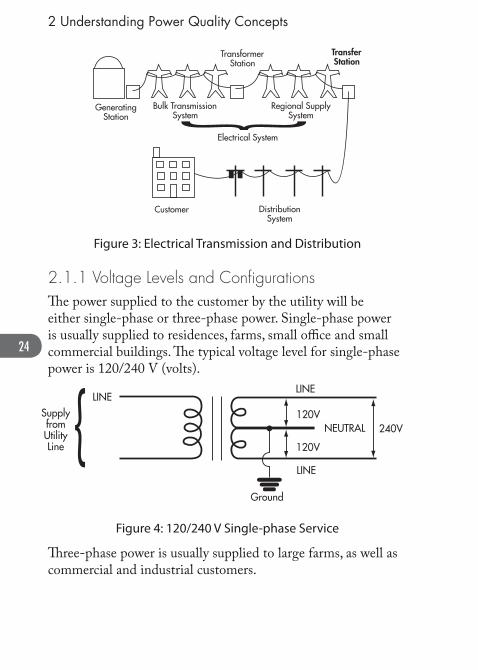
2.1.1 Voltage Levels and Confi gurationsTh e power supplied to the customer by the utility will be either single-phase or three-phase power. Single-phase power is usually supplied to residences, farms, small offi ce and small commercial buildings. Th e typical voltage level for single-phase power is 120/240 V (volts).
LINESupplyfromUtilityLine
LINE
120V
120V
LINE
Ground
NEUTRAL 240V
Figure 4: 120/240 V Single-phase Service
Th ree-phase power is usually supplied to large farms, as well as commercial and industrial customers.
25
2 Understanding Power Quality Concepts
LINE
SupplyfromUtility
LINE
LINE
LINE
LINE
LINE
NEUTRAL
GroundLine to Neutral Voltage – 120VLine to Line Voltage – 208V
NEUTRAL
Figure 5: Typical 208 V Three-phase Wye Connected Service
Typical voltage levels for three phase power supply are 120 V/208 V, 277 V/480 V (in the United States and Canada) or
347 V/600 V (in Canada).
Rotating equipment such as large motors and other large equip-ment require three-phase power to operate, but many loads require only single-phase power. Single-phase power is obtained from a three-phase system by connecting the load between two phases or from one phase to a neutral conductor.
Diff erent connection schemes result in diff erent voltage levels being obtained.
26
2 Understanding Power Quality Concepts
NG
208V480V600V
120V277V347V
Ø to N VoltageØ to Ø Voltage
ØØ
Ø
Figure 6: Grounded Wye Connection
2.1.2 Site DistributionElectrical power enters the customer’s premises via the service entrance and then passes through the billing meter to the panel board (also referred to as the “fuse box”, “breaker panel”, etc.). In most residential or commercial installations electrical circuits will be run from this panel board.
ServiceEntrance
BillingMeter
Panel Board
Circuits
Figure 7: Typical Residential Service
In larger distribution systems this power panel board will supply other panel boards which, in turn, supply circuits.
27
2 Understanding Power Quality Concepts
BillingMeter
Panel Board
Panel Board
Panel Board
Circuits
Circuits
Circuits
Figure 8: Service with Branch Panel Boards
A transformer is used if a diff erent voltage or isolation from the rest of the distribution system is required. Th e transformer eff ectively creates a new power supply system (called a sepa-rately derived power source) and a new grounding point on the neutral.
Panel Board
Transformer
208VPanel Board
208V480V
Figure 9: Typical Transformer Installation
28
2 Understanding Power Quality Concepts
2.2 Basic Power Quality Concepts
2.2.1 Grounding and BondingGrounding
Grounding is one of the most important aspects of an electrical distribution system but often the least understood. Your Electrical Code sets out the legal requirements in your jurisdiction for safety standards in electrical installations.
For instance, the Code may specify requirements in the following areas:
(a) Th e protection of life from the danger of electric shock, and property from damage by bonding to ground non-current-carrying metal systems;
(b) Th e limiting of voltage on a circuit when exposed to higher voltages than that for which it is designed;
(c) Th e limiting of ac circuit voltage-to-ground to a fi xed level on interior wiring systems;
(d) Instructions for facilitating the operation of electrical apparatus
(e) Limits to the voltage on a circuit that is exposed to light-ning.
In order to serve Code requirements, eff ective grounding that systematically connects the electrical system and its loads to earth is required.
Connecting to earth provides protection to the electrical system and equipment from superimposed voltages from lightning and contact with higher voltage systems. Limiting over voltage with respect to the earth during system faults and upsets provides for a more predictable and safer electrical system. Th e earth ground
29
2 Understanding Power Quality Concepts
also helps prevent the build-up of potentially dangerous static charge in a facility.
Th e grounding electrode is most commonly a continuous electrically conductive underground water pipe running from the premises. Where this is not available the Electrical Codes describe other acceptable grounding electrodes.
Grounding resistances as low as reasonably achievable will reduce voltage rise during system upsets and therefore provide improved protection to personnel that may be in the vicinity.
Connection of the electrical distribution system to the ground-ing electrode occurs at the service entrance. Th e neutral of the distribution system is connected to ground at the service entrance. Th e neutral and ground are also connected together at the secondary of transformers in the distribution system. Connection of the neutral and ground wires at any other points in the system, either intentionally or unintention-ally, is both unsafe (i.e., it is an Electrical Code violation) and a power quality problem.
Equipment Bonding
Equipment bonding eff ectively interconnects all non-current carrying conductive surfaces such as equipment enclosures, raceways and conduits to the system ground.
Th e purpose of equipment bonding is:
1) To minimize voltages on electrical equipment, thus providing protection from shock and electrocution to personnel that may contact the equipment. 2) To provide a low impedance path of ample current-carrying capability to ensure the rapid operation of over-current devices under fault conditions.
30
2 Understanding Power Quality Concepts
120V appears on enclosure presentinga hazard to personnel
LOAD
Short to Enclosure Enclosure
Ground
15A Breaker
120V
Figure 10: Equipment without Proper Equipment Bonding
Fault current flowsthrough safety groundand breaker opens.No voltage appears onenclosure. No safetyhazard.
LOAD
Short to Enclosure Enclosure
Ground
15A Breaker Opens
Fault Current
Safety Ground
120V
Figure 11: Equipment with Proper Equipment Bonding
If the equipment were properly bonded and grounded the equipment enclosure would present no shock hazard and the ground fault current would eff ectively operate the over-current device.
31
3 Power Quality Problems
3 POWER QUALITY PROBLEMS
3.1 How Power Quality Problems DevelopTh ree elements are needed to produce a problematic power line disturbance:
A source•
A coupling channel•
A receptor •
If a receptor that is adversely aff ected by a power line deviation is not present, no power quality problem is experienced.
DisturbanceSource
CouplingChannel
Receptor
Figure 12: Elements of a Power Quality Problem
Th e primary coupling methods are:
1. Conductive coupling A disturbance is conducted through the power lines into the equipment.
2. Coupling through common impedance Occurs when currents from two diff erent circuits fl ow through common impedance such as a common ground. Th e voltage drop across the impedance for each circuit is infl uenced by the other.
3. Inductive and Capacitive Coupling Radiated electromagnetic fi elds (EMF) occur during the
32
3 Power Quality Problems
operation of arc welders, intermittent switching of contacts, lightning and/or by intentional radiation from broadcast antennas and radar transmitters. When the EMF couples through the air it does so either capacitively or inductively. If it leads to the improper operation of equipment it is known as Electromagnetic Interference (EMI) or Radio Frequency Interference (RFI). Unshielded power cables can act like receiving antennas.
Once a disturbance is coupled into a system as a voltage deviation it can be transported to a receptor in two basic ways:
1) A normal or transverse mode disturbance is an unwanted potential diff erence between two current-carrying circuit conductors. In a single-phase circuit it occurs between the phase or “hot” conductor and the neutral conductor.
2) A common mode disturbance is an unwanted potential diff erence between all of the current-carrying conduc-tors and the grounding conductor. Common mode disturbances include impulses and EMI/RFI noise with respect to ground.
Th e switch mode power supplies in computers and ancillary equipment can also be a source of power quality problems.
Th e severity of any power line disturbance depends on the relative change in magnitude of the voltage, the duration and the repetition rate of the disturbance, as well as the nature of the electrical load it is impacting.
33
3 Power Quality Problems
3.2 Power Quality DisturbancesCategory Typical Spectral Cintent Typical Duration Typical Voltage
Magnitude
1 .0 Transients
1.1 Impulsive Transient 1.1.1 Nanosecond 5 ns rise <50 ns 1.1.2 Microsecond 1us rise 50 ns -1 ms 1.1.3 Millisecond 0.1 ms rise >1 ms 1.2 Oscillatory Transient 1.2.1 Low Frequency <5 kHz 0.3-50 ms 0-4 per unit 1.2.2 Medium Frequency 5-5000 kHz 20 us 0-8 per unit 1.2.3 High Frequency 0.5-5 mHz 5 us 0-4 per unit2.0 Short Duration Variations 2.1 Instantaneous 2.1.1 Sag 0.5-30 cycles 0.1-0.9 per unit 2.1.2 Swell 0.5-30 cycles 1.1-1.8 per unit 2.2 Momentary 2.2.1 Interruption 0.5-30 cycles <0.1 per unit 2.2.2 Sag 30 cycles-3 s 0.1-0.9 per unit 2.2.3 Swell 30 cycles-3 s 1.1-1.4 per unit 2.3 Temporary 2.3.1 Interruption 3 s-1 min <0.1 per unit 2.3.2 Sag 3 s-1 min 0.1-0.9 per unit 2.3.3 Swell 3 s-1 min 1.1-1.2 per unit3.0 Long Duration Variations 3.1 Sustained Interruption >1 min 0.0 per unit 3.2 Under-voltages >1 min 0.8-0.9 per unit 3.3 Over voltages >1 min 1.1-1.2 per unit4.0 Voltage Imbalance Steady State 0.5-2%5.0 Waveform Distortion 5.1 DC Offset 0-100th Harmonic Steady State 0-0.1% 5.2 Harmonics 0-6 KHz Steady State 0-20% 5.3 Inter-harmonics Steady State 0-2% 5.4 Notching Steady State 5.5 Noise Broadband Steady State 0-1%6.0 Voltage Fluctuations <25 Hz Intermittent 0.1-7%
7.0 Frequency Variations <10 s
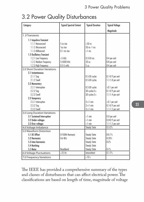
Th e IEEE has provided a comprehensive summary of the types and classes of disturbances that can aff ect electrical power. Th e classifi cations are based on length of time, magnitude of voltage
34
3 Power Quality Problems
disturbance and the frequency of occurrence. Th ese classifi ca-tions are shown in the previous table.
3.3 Load Sensitivity: Electrical Loads that are Affected by Poor Power Quality
3.3.1 Digital ElectronicsDigital electronics, computers and other microprocessor based equipment may be more sensitive to power line disturbances than other electrical equipment depending on the quality of their power supply and how they are interconnected. Th e circuits in this equipment operate on direct current (DC) power. Th e source is an internal DC power supply which converts, or rectifi es, the AC power supplied by the utility to the various DC voltage levels required. A computer power supply is a static converter of power. Variations in the AC power supply can therefore cause power quality anomalies in comput-ers.
Th e Computer Business Equipment Manufacturers Association Curve (CBEMA, now called the ITIC Curve) published in the IEEE Orange Book is intended to illustrate a suggested computer susceptibility profi le to line voltage variations. Th e ITIC curve is based on generalized assumptions, is not an industry standard and is not intended for system design purposes. No ITIC member company is known to have made any claim for product performance or disclaimer for non-performance for their products when operated within or outside the curve. Th e ITIC curve should not be mistakenly used as a utility power supply performance curve.
35
3 Power Quality Problems
ITI (CBEMA) Curve(Revised 2000)
Prohibited Region
No Interruption In Function Region
No Damage Region
Perc
ent o
f Nom
inal
Vol
tage
(RM
S or
Pea
k Eq
uiva
lent
)
Voltage Tolerance EnvelopeApplicable to Single-Phase120-Volt Equipment
500
400
300
200
140
120
100
8070
40
110
90
0
1us.001 c 0.01 c
1 ms 3 ms 20 ms 0.5 s 10 s SteadyState
Duration in Cycles (c) and Seconds (s)
1 c 10 c 100 c
Figure 13: Computer Susceptibility Profi le to Line Voltage Variations and Disturbances – The ITIC Curve
36
3 Power Quality Problems
Th e susceptibility profi le implies that computers can tolerate slow variations from -13% to + 5.8%, and greater amplitude disturbances can be tolerated as their durations become shorter. In fact, many computers can run indefi nitely at 80% of their nominal supply voltage; however, such operation does lead to premature wear of the power supply.
While the operating characteristics of computer peripherals may at one time have been more dependent on the types of power supply designs and components used, generalizations that infer that computers are highly sensitive to small deviations in power quality are no longer true.
Th ere is also no validity in the contention that, as the operating speed of a computer increases, so does its sensitivity to voltage variations. IT equipment sensitivity is due to the manner in which its power supply components interact with the supplied AC power.
3.3.2 LightingTh ere are three major eff ects of voltage deviations on lighting: 1. Reduced lifespan 2. Change of intensity or output (voltage fl icker) 3. Short deviations leading to lighting shutdown and long
turn-on times
For incandescent lights the product life varies inversely with applied voltage, and light output increases with applied voltage. In High Intensity Discharge (HID) lighting systems, product life varies inversely with number of starts, light output increases with applied voltage and restart may take considerable time. Fluorescent lighting systems are more forgiving of voltage deviations due to the nature of electronic ballasts. Ballasts may overheat with high applied voltage and these lights are usually less susceptible to fl icker.
37
3 Power Quality Problems
Information on lighting is available from the companion “lighting reference guide” that can be easily found through the various internet web search engines.
3.3.3 MotorsVoltages above the motor’s rated value, as well as voltage phase imbalance, can cause increased starting current and motor heat-ing. Reduced voltages cause increased full-load temperatures and reduced starting torques.
3.4 Types and Sources of Power Quality Problems
3.4.1 Transients, Short Duration and Long Duration Variations
A general class of power quality variations (summarized in the following charts) are instantaneous variations. Th ese are subdivided as:
Transients (Impulsive and Oscillatory; up to 50 ms)•
Short-Duration (0.5 cycles to 1 minute)•
Long-Duration (>1 minute but not a steady state phenom-• enon)
Generally, instantaneous variations are unplanned, short-term eff ects that may originate on the utility line or from within a facility. Due to the nature and number of events that are covered by this class of power quality problem, a summary chart has been provided to highlight the key types of variation.
38
3 Power Quality Problems
39
3 Power Quality Problems
Power Line Disturbances Summary
40
3 Power Quality Problems
Power Line Disturbances Summary (1 of 4)
DISTURBANCES SYMPTOMS POSSIBLE CAUSES POSSIBLE RESULTS COMMENTS AND SOLUTIONS
41
Power Line Disturbances Summary
• high amptitude, short duration voltage disturbances
• can occur in common and normal mode
• switching inductive loads on or off (motors, relays, transformers, x-ray equipment, lighting ballasts)
• operation of older UPS/SPS systems may cause notching
• electronic interference• microprocessor based equipment
errors• hardware damage of electronic
equipment• current limiting fuse operation
• Transient problems are mainly due to the increased use of electronic equipment without regard for the realities of normal power system operation and the operation of the customers’ facility
• It is sometimes very difficult to trace the source of a transient.
• Transients usually have less energy than momentary disturbances.
• Transient suppressors rarely protect against equipment generated transients.
• There is a general consensus that most transients get into computer logic and memory circuits through poor wiring or EMI, not by conduction.
• Normal mode impulses are typi-cally the result of the switching of heavy loads, or of power factor connection capacitors.
• Common mode impulses are often caused by lightning.
High frequency oscillations (from a few hundred Hz to 500 kHz) that decay to zero within a few milliseconds
Impulsive Non-Periodic
Impulsive Periodic
Oscillatory
Non-periodic impulses which increase instantaneous voltage
Periodic impulses which increase or decrease the instantaneous voltage
DISTURBANCES SYMPTOMS POSSIBLE CAUSES POSSIBLE RESULTS COMMENTS AND SOLUTIONS
SH
OR
T
DU
RA
TIO
N
DIS
TU
RB
AN
CE
S
• When starting large loads, such as motors, high inrush currents are produced which drop the voltage for short periods. This is a relatively common problem and can be prevented by using reduced voltage motor starters, by reducing the number of large loads operating simul-taneously, by restricting the number of motor starts at any given time, by transferring the large load to its own circuit, by upgrading feeder voltage, and by using cable of proper rating.
• Although lightning may initially cause voltage spikes or surges near its point of impact, surge arrestors momentarily shorten the power line, producing sags that may be conducted for a consider-able distance through the system.
• Electrical equipment may respond to a sag as it would to a power interruption.
Low voltage in one or more phases
• starting large loads (motors, air conditioners, electric furnaces, etc)
• overloaded wiring and incorrect fuse rating
• fuse and breaker clearing• lightning (indirect cause due to
Undervoltage Any long-term change above (overvoltages) or below (undervoltages) the prescribed input voltage range for a given piece of equipment. (undervoltages) the prescribed input voltage range for a given piece of equipment.
• overloaded customer wiring loose or corroded connections
• unbalanced phase loading conditions
• faulty connections or wiring overloaded distribution system
• incorrect tap setting• reclosing activity
• errors of sensitive equipment• low efficiency and reduced life
of electrical equipment, such as some motors, heaters
• lengthens process time of infrared and resistance heating processes
• hardware damage• dimming of incandescent lights,
and problems in turning on fluorescent lightsBrownouts A type of voltage fluctua-
tion. Usually a 3-5% voltage reduction.
• poor wiring or connections• high power demand within building
or local area• intentional utility voltage reduction
to reduce load under emergency system conditions
• planned utility testing
• Some municipal utilities have a list of overloaded distribution transformers, which can indicate areas prone to undervoltage conditions.
• Undervoltages can be reduced by practicing regular mainte-nance of appliance cable and connections, checking for proper fuse ratings, transferring loads to separate circuits, selecting a higher transformer tap setting, replacing an overloaded transformer or providing an additional feeder.
Overvoltage • improper application of power factor correction capacitors
• incorrect tap setting
• overheating and reduced life of electrical equipment and lighting
• blistering of infrared processes
• Ensuring that any power factor correction capacitors are properly applied
• Changing the transformers tap setting
44
Power Line Disturbances Summary
Power Line Disturbances Summary (4 of 4)
DISTURBANCES SYMPTOMS POSSIBLE CAUSES POSSIBLE RESULTS COMMENTS AND SOLUTIONS
LO
NG
D
UR
AT
ION
D
IST
UR
BA
NC
ES
Power Interruptions Duration: • momentary interruptions: , 3 s • sustained interruptions: . 1 minCoupling Mechanism: • conductive
Power Interruptions Total loss of input voltage. Often referred to as a “blackout” or “failure” for events of a few cycles or more, or “dropout” or “glitch” for failures of shorter duration.
• operation of protective devices in response to faults that occur due to acts of nature or accidents
• malfunction of customer equip-ment
• fault at main fuse box tripping supply
• loss of computer/controller memory
• equipment shutdown/failure• hardware damage• product loss
• employing UPS systems, • allowing for redundancy, • installing generation facilities in
the customer’s facility
45
3 Power Quality Problems
3.4.2 Steady State Disturbances
3.4.2.1 Waveform Distortion and Harmonics
Harmonics are currents and voltages with frequencies that are whole-number multiples of the fundamental power line fre-quency (which is 60 Hz in North America). Harmonics distort the supplied 60 Hz voltage and current waveforms from their normal sinusoidal shapes.
Each harmonic is expressed in terms of its order. For example, the second, third, and fourth order harmonics have frequencies of 120 Hz, 180 Hz, and 240 Hz, respectively. As order, and therefore frequency, of the harmonics increases, the magnitude normally decreases. Th erefore, lower order harmonics, usually the fi fth and seventh, have the most eff ect on the power system. Due to the nature of power conversion techniques, odd num-bered harmonics are usually the only frequencies of concern when dealing with harmonic problems. Th e presence of low levels of even harmonics in a system requires expert mitigation advice from a power quality professional.
Th e eff ect of a given harmonic on the power system can be seen by superimposing the harmonic on the fundamental waveform, to obtain a composite:
46
3 Power Quality Problems
Initially In-Phase
0
0
Time
sin (x)
sin (x) + .33 sin(3x)
.33 sin(3x)
Time
Volta
geVo
ltage
Figure 14: Superposition of Harmonic on Fundamental: Initially In-Phase
In this example, the two waveforms begin in-phase with each other, and produce a distorted waveform with a fl attened top. Th e composite waveform can be changed by adding the same harmonic, initially out-of-phase with the fundamental, to obtain a peaked eff ect:
47
3 Power Quality Problems
Initially Out-Of-Phase
0
0
Time
sin (x)
sin (x) – .33 sin(3x)
–.33 sin(3x)
Time
Volta
geVo
ltage
Figure 15: Superposition of Harmonic on Fundamental: Initially Out-of-Phase
Harmonics can be diff erentiated from transients on the basis that transients are not periodic and are not steady state phe-nomena.
Production and Transmission
Most harmonics result from the operation of customer loads, at residential, commercial and industrial facilities.
48
3 Power Quality Problems
Common Sources of Harmonics
Sector Sources Common Problems
Industrial Variable speed drives welders, large UPS systems, lighting system
• Overheating and fuse blowing of power factor correction capacitors
• Overheating of supply transformers
• Tripping of overcurrent protection
Commercial Computers, electronic offi ce equipment, lighting
• Overheating of neutral conductors and transformers
• Interference
Residential Personal computers, lighting, electronic devices
• Generally not a problem
• However, high density of electronic loads could cause overheating of utility transformers
Figure 16: Main Sources of Harmonics
Harmonics are caused by any device or equipment which has nonlinear voltage-current characteristics. For example, they are produced in electrical systems by solid state power converters such as rectifi ers that conduct the current in only a portion of each cycle. Silicon Controlled Rectifi ers (SCRs) or thyristors are examples of this type of power conversion device.
Th e levels of harmonic current fl owing across the system im-pedance (which varies with frequency) determine the harmonic voltage distortion levels.
49
3 Power Quality Problems
200 V/div vertical
1000 V
–1000 V
0 V
5.0 ms/div horizontalPH B–NEUT INITIAL WAVE SHP
Time
Volta
ge
Figure 17: Harmonics Produced by Three-Phase Controlled Loads
(Reproduced with Permission of Basic Measuring Instruments, from “Handbook of Power Signatures”, A. McEachern,1988)
Aside from solid state power converters, loads may also produce harmonics if they have nonlinear characteristics, meaning that the impedance of the device changes with the applied voltage. Examples include saturated transformers and gaseous discharge lighting, such as fl uorescent, mercury arc and high pressure sodium lights.
As harmonic currents fl ow through the electrical system, they may distort the voltage seen by other electrical equipment. Since the system impedances are usually low (except during resonance), the magnitudes of the voltage harmonics, and the extent of voltage distortion are usually lower than that for the corresponding current distortion. Harmonics represent a steady state problem, since they are present as long as the harmonic generating equipment is in operation.
50
3 Power Quality Problems
Th ird harmonic currents are usually most apparent in the neutral line. Th ese occur due to the operation of single-phase nonlinear loads, such as power supplies for electronic equip-ment, computers and lighting equipment.
As lighting equipment has been a cause of many neutral problems adequate precaution must be taken to mitigate the harmonic emission of lighting equipment, in particular in case of re-lamping. Th ese harmonic currents occur due to the opera-tion of single-phase nonlinear loads, such as power supplies for electronic equipment and computers. Th e third harmonic produced on each phase by these loads adds in the neutral. In some cases, the neutral current can be larger than the phase currents due to these third harmonics.
Eff ects of Harmonics
In many cases, harmonics will not have detrimental eff ects on equipment operation. If the harmonics are very severe, however, or if loads are highly sensitive, a number of problems may arise. Th e addition of power factor correction capacitors to harmonic producing loads can worsen the situa-tion, if they have parallel resonance with the inductance of the power system. Th is results in amplifying the harmonic currents producing high harmonic voltages.
Harmonics may show up at distant points from their source, thus causing problems for neighbouring electrical end-users, as well as for the utility. In fl owing through the utility supply source impedance, harmonic currents produce distortion in the utility feeder voltage.
51
3 Power Quality Problems
EQUIPMENT HARMONIC EFFECTS RESULTS
Capacitors (all; not just those for power factor correction)
– capacitor impedance decreases with increasing frequency, so capacitors act as sinks where harmonics converge; capacitors do not, however, generate harmonics
– supply system inductance can resonate with capacitors at some harmonic frequency causing large currents and voltages to develop
– dry capacitors cannot dissipate heat very well, and are therefore more susceptible to damage from harmonics
– breakdown of dielectric material
– capacitors used in computers are particularly susceptible, since they are often unprotected by fuses or relays
– heating of capacitors due to increased dielectric losses
– short circuits
– fuse failure
– capacitor failure
Transformers – current harmonics cause higher transformer losses
– transformer heating
– reduced life
– increased copper and iron losses
– insulation stress
– noise
Figure 18: Harmonic Eff ects on Equipment
52
3 Power Quality Problems
In addition to electrical conduction, harmonics can be coupled inductively or capacitively, thus causing interference on analog telecommunication systems. For example, humming on tele-phones can be caused by induced harmonic distortion.
A power harmonic analysis can be used to compare distortion levels against limits of acceptable distortion. In addition, the operation of some solid state devices will produce a notched eff ect on the voltage waveform.
Harmonic Prevention and Reduction
It is very important when designing an electrical system, or retrofi tting an existing one, to take as many precautions as necessary to minimize possible harmonic problems. Th is requires advanced planning and, potentially, additional capital. Th e complete electrical environment must be considered.
Filters
Harmonic fi lters can be used to reduce the amplitude of one or more harmonic currents or voltages. Filters may either be used to protect specifi c pieces of equipment, or to eliminate harmon-ics at the source. Since harmonic fi lters are relatively large, space requirements may have to be budgeted for.
In some situations, improperly tuned fi lters may shift the resonant frequencies close to the characteristic harmonics of the source. Th e current of the high harmonics could excite the resonant circuit and produce excessive voltages and attract high oscillating harmonic currents from elsewhere in the system.
Capacitors
Harmonic amplifi cation due to resonance associated with capacitor banks can be prevented by using converters with high pulse numbers, such as twelve pulse units, thereby reducing
53
3 Power Quality Problems
high-amplitude low order harmonics. A similar eff ect occurs with pulse width modulated converters.
Method Advantages Disadvantages
Change the size of the capacitor bank to shift the resonant point away from the major harmonic
• vulnerable to power system changes
• relatively low incremental cost
• ease of tuning
Place an inductor in series with the capacitor bank, and tune their series resonance below the major harmonics
• better ability to minimize harmonics
• fl exibility for changing load conditions
• series inductor increases the fundamental frequency voltage of the capacitor; therefore, a higher rated capacitor may be required
Telephone Line Interference
Telephone interference can be reduced by the aforementioned prevention and reduction methods, by rerouting the telephone lines, improved shielding and balance of telephone cables, compatible grounding of telephone cables, or by reducing the harmonic levels on the power line. Th e degree of telephone interference can be expressed in terms of the Telephone Inter-ference Factor (TIF).
Harmonic Study
Single calculation of resonant frequencies, transient network analysis, and digital simulation are among the techniques available today to perform harmonic studies. Th ese tools could be used to accurately model the power network, the harmonic sources, and perform the harmonic analysis in the same manner as traditional load fl ow, short circuit and transient stability stud-ies are conducted. Experienced consultants may be approached to conduct or assist in a harmonic study.
54
3 Power Quality Problems
Equipment Specifi cations
Consider the eff ect on your power system when ordering harmonic producing equipment. Large projects may require a pre-installation harmonic study. Be prepared for fi ltering requirements if necessary to ensure compatibility with the power system. If a harmonic fi lter is required, a description of the power system should be considered in its design, including:
Fault level at the service entrance •
Rating and impedance of transformers between the service • entrance and the input to the power conditioning equip-ment
Details of all capacitor banks in the facility.•
Where a choice is available, consider using equipment with low harmonic emission characteristics. Th is should be explicitly stated in the manufacturer’s literature. Where Variable Speed Drives (VSDs) will be deployed, active front end designs generate lower harmonic levels and have a power factor close to unity. Variable Speed Drives are also the same equipment as Adjustable Speed Drives (ASDs); Variable Frequency Drives (VFDs); Adjustable Frequency Drives (AFDs), etc.
3.4.2.2 Flicker
Flicker is the impact a voltage fl uctuation has on the luminous intensity of lamps and fl uorescent tubes such that they are perceived to ‘fl icker’ when viewed by the human eye. Th e level at which it becomes irritating is a function of both the magnitude of the voltage change and how often it occurs. A voltage fl icker curve indicates the acceptable magnitude and frequency of voltage fl uctuations on a distribution sys tem. Flicker is caused by rapidly changing loads such as arc furnaces, electrical welders, and the starting and stopping of motors.
55
3 Power Quality Problems
5
4
3
2
1
1 12 2 2 3 4 6 10 153 4 610 1020 2030 30 60
0
Border Linesof Visibility
Border Linesof Irritation
Solid Lines composite curves of voltage flicker studies byGeneral Electric company. General Electric Review August 1925:Kansas City Power & Light Company, Electrical World, May 19,1934: T&D Committee, EEI, October 24, 1934. Chicago: Detroit Edison Company: West Pennsylvania Power Company: Public Service Company of Northern Illinois.
Dotted Lines voltage flicker allowed by two utilities,referencesElectrical World November 3, 1958 and June 26, 1961.
% Vo
ltage
Fluc
tuat
ion
Fluctuations Per Hour
House PumpsSump Pumps
A/C EquipmentTheatrical Lighting
Domestic RefrigeratorsOil Burners
Single ElevatorHoistsCranes
Y-Delta Changes on Elevator-Motor-Generator Sets
X-Ray Equipment
Arc FurnacesFlashing SignsArc-Welders
Drop HammersSaws
Group Elevators
Reciprocating PumpsCompressors
Automatic Spot Welders
Fluctuations Per Minute Fluctuations Per Second
Figure 19: Flicker Curve IEEE 519-1992
3.4.3 Distribution and Wiring Problems Many power quality problems are due to improper or ineff ective electrical distribution wiring and/or grounding within the customer’s site.
Grounding and distribution problems can result from the following:
Improper application of grounding electrodes or mistakenly • devising alternate “grounds” or grounding systems
High impedances in the neutral current return path or fault • current return path
Excessive levels of current in the grounding system, due to • wiring errors or equipment malfunction
It must be realized that although mitigating equipment when properly applied will resolve voltage quality problems, it will do nothing to resolve wiring or grounding problems. It is essential that the site distribution and grounding system be designed and installed properly and in accordance with the applicable
56
3 Power Quality Problems
Electrical Safety Code to ensure the safety of personnel and proper equipment operation. All electrical equipment used must be approved by the applicable authority, such as the CSA or UL, or inspected by the local authority in order to ensure that regulatory minimum safety standards have been achieved.
3.4.3.1 Fault Protection in Utility Distribution Systems
Faults resulting in overvoltages and over-currents may occur in the utility system, typically due to lightning, construction, accidents, high winds, icing, tree contact or animal intervention with wires.4 Th ese faults are normally detected by over-current relays which initiate the operation of fault clearing by equipment.
Faults may be classifi ed as temporary or permanent. Temporary faults may be caused by momentary contact with tree limbs, lightning fl ashover, and animal contact. Permanent faults are those which result in repairs, maintenance or equipment replacement before voltage can be restored. Protection and control equipment automatically disconnects the faulted portion of a system to minimize the number of customers aff ected.
Th e utility distribution system includes a number of devices such as circuit breakers, automatic circuit re-closers and fused cutouts which clear faults. Automatic re-closers and re-closing breakers restore power immediately after temporary faults. Fused cutouts that have operated must have their fuse replaced before power can be restored. Th ese protective devices can reduce the number of customers aff ected by a fault, reduce the duration of power interruptions resulting from temporary faults
4 - A worst case event of tree contact with utility lines contributing to power problems took place on August 15, 2003. See “U.S.- Canada Power System Outage Task Force Final Report on the August 14, 2003 Blackout in the United States and Canada: Causes and Recommendations,” April 2004.
57
3 Power Quality Problems
and assist in locating a fault, thereby decreasing the length of interruptions.
Automatic reclosers and reclosing breakers open a circuit on over-current to prevent any further current fl ow, and reclose it after a short period of time. If a fault does not disappear after one reclosure operation, additional opening/reclosing cycles can occur.
FaultPersists
CircuitOpen
CircuitClosed
FaultStart
Time
t t t
CircuitRecloses
CircuitOpens;
First ReclosureInitiated
CircuitReopens;
Second ReclosureInitiated
CircuitReopens;
Third ReclosureInitiated
FaultPersists
Figure 20: Example of a Repetitive Reclosure Operation
Normally a few seconds are required to clear a fault and energize the appropriate circuitry for a reclosure. Th e reclosing interval for a recloser is the open circuit time between an automatic opening and the succeeding automatic reclosure. In the above diagram, three intervals of duration ‘t’ are indicated.
Some hydraulic reclosers may be able to provide instantaneous (0.5 seconds) or four second reclosing intervals. In addition to these reclosers, circuit breakers at substations, on the secondary or distribution side, are equipped with timers which allow a range of reclosing times to be selected. A commonly available range is 0.2 to 2 seconds.
58
3 Power Quality Problems
125 V
105 V
0 V
200 V
20.0 V/div vertical 2 sec./div horizontalLINE–NEUT VOLTAGE SAG
Volta
ge
Time
Figure 21: Eff ect of Multiple Reclosure Operation on Voltage
(Reproduced with Permission of Basic Measuring Instruments, from “Handbook of Power Signatures”, A. McEachern,1988)
Reclosing Interval (Seconds)
Type of Control t1 t2 t3
Hydraulic 2 2 2
Electronic <0.5 2 5-10
Figure 22: Reclosing Interval for Hydraulic and Electrical Control Types (“t1” 1st reclosing operation etc.)
When a solid fault on a feeder is cleared, the voltage at the fault point declines to near zero instantaneously. However, the time
59
3 Power Quality Problems
constant in the detection circuitry results in the graph above. In this fi gure, small voltage rises indicate when reclosure was attempted unsuccessfully due to the persistence of the fault.
If a fault persists, the recloser or breaker may lock open, or a fuse or sectionalizer will operate. An autoreclosure on one feeder that is faulted can produce a disturbance that travels on neighbouring feeders.
Customers frequently mistake the eff ects of a temporary (0.5s - 2s) interruption, such as the loss of time-keeping abilities of digital clocks, as evidence of a sustained power interruption. Th e fact that most High Intensity Discharge (HID) lighting, which is frequently used in industrial settings, can take 10-20 minutes to come back on after a fault has cleared is a further example of an apparent power supply problem that actually represents normal operation of the utility distribution network. Th e lengthy period of time before light is restored results from the characteristics of the lighting system. Although special HID systems are available that eliminate this problem, they do not represent the majority that are currently used.
3.4.4 Voltage UnbalanceA voltage unbalance is a condition in a three-phase system in which the measured r.m.s. values of the phase voltages or the phase angles between consecutive phases are not all equal. Volt-age unbalance is a signifi cant concern for users that have poorly distributed loads and impedance mismatches. An excessive level of voltage unbalance can have serious impacts on induction motors, leading to large ineffi ciencies causing over-heating and winding failure. Excessive losses in the motor may cause over-current protection systems to operate. Although induction motors are designed to accept a small level of unbalance they have to be derated if the voltage unbalance is 2% or higher. If an induction motor is oversized, then some protection is built into
60
3 Power Quality Problems
its operation although the motor does not operate at the best effi ciency and power factor. Voltage unbalance may also have an impact on AC variable speed drive systems unless the DC output of the drive rectifi er is well fi ltered.
Th ere are two major sources of voltage unbalance:
1) the unbalance of load currents, which can be controlled by making sure load currents are balanced to within 10%
2) high impedance or open neutrals, which represent a major wiring fault that needs to be corrected by your electrician.
3.5 Relative Frequency of OccurrenceFrequently, the source of a disturbance originates within a customer’s plant or building. Some pre-existing data studies conducted in the United States indicate that as many as 90% of the origins of power quality problems originate within a customer’s or a neighbour’s facility. Many of these disturbances are due to the use of disturbance producing equipment, improper wiring and grounding, or the misapplica-tion of mitigating equipment.
Some disturbances are caused by normal utility operations such as fault clearing, capacitor switching, and line switching. Although fewer in number than those generated within a facility, these events can cause great diffi culty for customers that have equip-ment incompatible with these normal operations.
61
3 Power Quality Problems
RelativePercent ofOccurrence(%)
100
80
60
40
20
0Sags
Voltage Disturbance
Impulses OvervoltagesPowerInterruptions
Figure 23: Relative Occurrence of Disturbances to Power Systems Supplying Computers
Source: Goldstein and Speranza, “The Quality of U.S. Commercial AC Power”; Proceedings of INTELEC Conference, 1982.
In 1991 and 2000, the Canadian Electrical Association under-took major studies of power quality in Canada – the National Power Quality Survey . Utilities from across the country performed monitoring at hundreds of sites. By comparing primary and secondary metered sites, the survey concluded that the average power quality provided by Canadian utilities is very good, and the average quality experienced by customers is good.
Th ere are considerable diff erences in the state of power quality between sites or locations. Th is is because of the large number of factors involved, such as customer equipment and wiring practices, the eff ects of neighbouring customers, geography and weather conditions. Sites that have a small independent power source, or one utility transformer that supplies a number of users, such as strip malls and large buildings, are particularly prone to power quality problems. Th is is because both disturb-ing and sensitive loads share the same power supply. In addition, the individual loads can represent a very large proportion of the total amount of electricity supplied to the building, so
62
3 Power Quality Problems
that changes in voltage can be very signifi cant when one of these loads is turned on or off . Frequently, customers unknow-ingly cause their own power quality problems by operating disturbance-producing process equipment in the same vicinity as electronic control devices.
From 1992 to 1995, the Electrical Power Research Institute (EPRI) collected data at 300 sites in the U.S. to assess utility power quality at the distribution level. A report* indicated that sites experienced an average of 9 voltage sag or inter-ruption events per year. In addition, the data indicated that voltage THD (Total Harmonic Distortion) peaked during late afternoon and evening periods. For residential feeders this data is consistent with past experience, since this is where harmonic sources such as television sets are the predominant load on the system.
63
3 Power Quality Problems
5th PercentileMean Average95th Percentile
Individual Voltage Harmonic Statistics for All SitesEach column represents a mean average of a given statistic for all DPQ sites
2.5
2.0
1.5
1.0
.5
0.0THD 2 3 4 5 6 7 8 9 10 11 12
% o
f Fun
dam
enta
l
Figure 24: Individual Voltage Harmonic Statistics 222 EPRI DPQ Sites from 6/1/93 to 6/1/94
(Reproduced with Permission of EPRI, from * “Preliminary Results For Eighteen Months of Monitoring from the EPRI Distribution Power Quality Project”, D. Sabin, T. Grebe, A. Sundaram, 1994)
3.6 Related Topics
3.6.1 Electromagnetic Compatibility (EMC)Electromagnetic compatibility is the term given to the measure and creation of electrical equipment that has both its suscepti-bility and transmission of electromagnetic noise reduced. Th e amount of reduction may be regulated by government rule or may be required to meet a certain operational requirement. Areas of EMC that may overlap with power quality are:
1) Extremely Low Frequency (ELF) magnetic fi eld interference from power lines (solved by distance, fi eld cancellation or shielding techniques)
2) Radiated noise from electronic devices (usually solved with fi ltering or shielding)
64
3 Power Quality Problems
3) Radiated noise from power wires (solved with re-routing, shielding or fi ltering)
4) Generation of harmonics by electrical loads (solved with fi ltering or re-design of the circuitry).
Electromagnetic Compatibility is a more involved and complex subject than can be adequately addressed in this guide. Th e international technical community has provided standard-ization activity under the IEC EMC committees (see http://www.iec.ch/zone/emc for more information).
3.7 Three Power Quality Case Studies
3.7.1 Case Study: Meter, Monitor & Manage: A proactive response to power quality
Th e site in question is located in a multi-story offi ce tower. Th e top four fl oors of the building have been designated as a “Business Recovery Center” (BRC) of a large fi nancial institu-tion. Th e function of the center is to provide backup, mirror and support services for the company’s business units. If a natural or operational disaster occurred, many of the business functions could be temporarily routed to this center. As a result, the BRC contains a signifi cant concentration of computing resources that need to be available at any time. Workstation computing requirements are based on the actual working systems used by line personnel.
Disaster and recovery planning must allow for unforeseen events. Even the best disaster planner will realize that some events contain the seeds for others; some problems are cascad-ing in nature and this requires adaptability on the part of the recovery center. At this location, electrical capacity has been designed to allow for increased loading from extra worksta-
65
3 Power Quality Problems
tions and servers that may be brought to the site subsequent to the on-set of a recovery situation and added to the existing complement of business equipment. Th is could result in system over-loading at some points in the distribution network. In the modern context of loading, harmonic currents need special attention, thus a real time monitoring system was requested to provide harmonic and true loading of the center’s distribution grid.
As was pointed out to the BRC personnel and engineering staff , for only a small additional cost, a total power quality monitoring system could be installed that would provide building envelope information along with distribution point data within the envelope. Th e BRC utilizes a 600 V base building distribution system. BRC business equipment transformers are fed from one of two bus risers, while mechanical equipment is fed from a separate 600 V bus duct. In the event of a total loss of utility power these bus ducts can be fed by two diesel generators that have an extended operating capability.
Th e following requirements were developed both from BRC requests and expert input from the various stakeholders:
Each dry-type transformer in the BRC was to be monitored • in order to provide current and harmonic loading, current and voltage distortion, voltage unbalance, and neutral current readings in real time
Power quality meters to provide transient, sag/swell and • waveform deviation graphs and statistics
Power quality thresholds must be programmable and • accessible
Energy monitoring must provide an aggregated table of • consumption criteria with graphs on a monthly basis
66
3 Power Quality Problems
All meters must be fully networked utilizing open standards • networking architectures and protocols
One of the key decisions that was made at this site on the basis of data viewed from the power quality component of the meters was with regard to Uninterruptible Power Supplies (UPS). Two issues arose that lead to cost savings. Th e fi rst of these concerned the need for a large on-site UPS system which was advocated by some. While servers require the ride-through of the UPS, management determined that the impact of transfer switching, while annoying for some is acceptable and that most workstations did not need the protection of 0.5 – 2 s of ride through aff orded by the UPS. Data from monthly generator tests revealed however that transfer switch wave shape anomalies were impacting the servers, leading to some network anomalies. Th e UPSs in use at the site were of a hybrid type that allowed transient and switching noise to pass through the UPS. UPSs were also subjected to excessive battery wear. Based on waveform data captured during testing, a decision was made to switch to an on-line UPS design and to institute a networked UPS management system.
Within 8 months of operation, an increased voltage unbalance was noted on a non-K-rated dry-type transformer. Normally this would indicate a high impedance neutral to ground bond which, if left undetected, would lead to overheating and equipment failure. A check of the meter revealed however that the neutral to ground bond on the meter was loose. Upon tightening this connection the voltage unbalance indication was corrected on the operator display.
Th is site’s experience with the monitoring system has been benefi cial in the following ways:
Data is presented to management that allows new insight • into equipment utilization
67
3 Power Quality Problems
Information is available at all times that can defi ne load • factors for key processes
Reporting is available that shows the size, shape and dura-• tion of building envelope power quality anomalies.
Th e money invested in the monitoring system has generated great returns in terms of the impact power quality data has had on equipment purchase and utilization since installation.
3.7.2 Case Study: High Demand Load in an Aircraft Assembly Facility
A pulsed laser system used by an aircraft manufacturer was used to number and identify wires on each and every plane manufac-tured. Th e unit was malfunctioning and would stop operating for short durations. Th e cost to the operation involved down-time of staff and equipment but, more importantly, inconsistent wire marking presented a massive safety liability.
Th e machine operated at 20 Hz supplied from a standard 120 V, 60 Hz single phase branch circuit. Th e system relied on an eff ective transfer of peak power from the power supply to the laser. Anything less than the peak power during pulse opera-tions resulted in reduced laser intensity with a consequent lack of quality in the process. Further investigation revealed that the quality of voltage at the site was distorted by 4.5%, and that the peaks of the voltage waveform were fl attening out.
A second point of concern occurred when the laser unit was powered up. Th ere was a large current inrush that led to a voltage notch and a drop in peak voltage. Th is is an impedance interaction: essentially the source is unable to provide the kind of current the load is asking for.
Moving beyond the start-up phase to a period when the laser was being “fi red”, the voltage fl at-topping was more obvious and the loss of peak voltage was chronic and severe. Th e peak power
68
3 Power Quality Problems
delivered to the laser was over 25% less than what was required. Product marking during this cycle was substandard.
Facility electricians were instructed to wire up a temporary source close to the laser load which had a lower impedance and higher capacity. Th is solution provided a healthier situation for the internal workings of the power supply, since capacitors reach full charge and more power was available for the laser.
Why was the capacity of the source increased? Nominally the unit operated on a 20 A breaker at 120 V giving us a rough capacity rating of 2400 VA. Th e system required large charging currents to power its laser, and therefore a source of 50 A at 120V, 6000 VA, was needed. It is not unusual to have to up-size source requirements considerably for loads of this type.
3.7.3 Case Study C: Motor Drive and Transformer Incompatibility in a Commercial BuildingTh is case study looks at a commercial offi ce building which utilizes two banks of AC motors with variable speed drives (VSDs) to control Heating, Ventilating and Air Conditioning (HVAC) functions. Each of the banks is serviced by its own 45 kVA transformer; the only loads on these transformers are the AC drives. Th e fi gure below shows a rather innocuous looking snapshot. Th e variable speed drives are rather like large switch-mode power supplies which demand peak current after reaching peak voltage.
Power quality experience tells one that a concentration of electronic, single phase loads leads to a 3rd harmonic neutral current. Th e neutral current in this case is shown in the second fi gure and can be seen to be primarily composed of 180 Hz. current, peaking above 150 Amps.
69
3 Power Quality Problems
Site 4 - Phase B-Neut. Snapshot 10:25:45 AM
200150100500
–50–100–150–200
200150100500
–50–100–150–200
Volts Am
ps
VoltageCurrent
Site 4 - Neut-Gnd Snapshot 10:25:45 AM
5
3
1
–1
–3
–5
200150100500
–50–100–150–200
Volts
Am
ps
VoltageCurrent
Th e major problem at this site was the intense heating in the service transformers. Th e problem became especially acute when tenants on the second fl oor complained about the smell of smoke from the transformers below them. Th e transformers were doing a fi ne job of providing isolation from the third harmonic; the problem was that they were not the right size for the electronic load. In order to provide a complete analysis of a transformer with regard to IEEE 519 harmonics guidelines, some calculations from the name-plate of the transformer needed to be performed.
70
3 Power Quality Problems
What was discovered was that the load on the transformers was at least 5 kVA over their nominal de-rated capacity which accounted for the severe heating. Both transformers were operating just above their maximum designed temperatures which will lead to premature insulation failure. What is not shown here, and was required to obtain the results is the raw data analysis from the power quality instrument that obtained the RMS and peak currents.
Th e solution for this site was new K-rated transformers for each drive bank. Given the isolated nature of the drives and the low neutral to ground voltage, there was no need for phase shifting transformers or special neutral current limiting devices.
71
4 Solving and Mitigating Electrical Power Problems
4 SOLVING AND MITIGATING ELECTRICAL POWER PROBLEMS
4.1 Identifying the Root Cause and Assessing Symptoms
Power quality technologists employ technical instrumentation. Th is instrumentation can range from simple digital multi-me-tering through to sophisticated waveform analysis instruments. True power quality monitoring requires full-time monitoring so that steady state eff ects can be trended and infrequent events can be captured as they occur. A variety of electronic meters are now available for permanent monitoring that off er numerous features at moderate prices.
A trained PQ specialist can also employ a portable instrument, or groups of instruments, to diagnose power quality for fi xed periods of time. It should be emphasized that power quality monitoring is a highly technical and potentially dangerous skill; even many trained electricians are completely unfamiliar with the details of how power quality measurement is properly carried out.
Do not attempt to undertake a power quality measurement exercise without the help of a professional practitioner in the fi eld.
One of the fi rst things that should be carried out before monitoring begins is a check of the eff ectiveness, safety and operational characteristics of the wiring in the facility. Th is will ensure that problems like bad grounding, poor terminations and improperly connected loads are not masking other problems or are, in fact, not mistaken for other types of issues.
72
4 Solving and Mitigating Electrical Power Problems
Some of the elements that might be tracked by a PQ profes-sional are:
RMS (Root - Mean - Square) Measurements•
Average Measurements•
Peak Measurements•
Harmonic Analysis•
Power Line Event Logging•
4.2 Improving Site ConditionsConsideration of disturbance sources external to the facility should only be considered after the internal electrical environ-ment has been thoroughly checked.
4.2.1 Mitigating EffectsTh e key elements to mitigate power quality problems are:
Proper grounding and wiring•
Eff ective mitigating equipment (if required)•
4.2.2 Mitigating EquipmentA wide variety of products are available that can help to miti-gate power line disturbances. Care should be taken to properly select eff ective mitigating equipment. Improper application of these products may cause new power quality problems due to unforeseen incompatibilities. Before selecting a product, the customer should have a good understanding of the cause of the problem, as well as the characteristics of the available equip-ment.
A properly functioning system may be adversely aff ected by change in the electrical environment, as in a change of load in the facility. Th erefore, mitigating equipment that was once
73
4 Solving and Mitigating Electrical Power Problems
eff ective may fail to protect sensitive equipment after such a change has occurred.
When selecting equipment that has an operational heat loss, as indicated by an effi ciency rating, provision should be made for adequate cooling of the equipment, especially if it is to be located in a computer room.
4.2.1.1 Dedicated Circuits
A dedicated circuit is a single circuit with one load. It is a relatively inexpensive distribution technique that can reduce load interaction. Th e ability of a dedicated circuit to solve power quality problems depends on its location, impedance, and other factors. To achieve the lowest possible impedance, theoretically, the load of the circuit should be as close as possible to the building service entrance. However, this could aggravate the situation if transients are a problem, since they could travel more freely through the system. For improved operation of the circuit, the neutral and the ground wires should be the same size as the current-carrying conductor.
Tips and Cautions
Dedicated circuits will solve local problems only. Properly installed dedicated circuits obviate the need for isolated ground-ing circuits.
4.2.1.2 Surge Protective Devices (SPDs; also known as Transient Voltage Surge Suppressors, TVSS)
SPDs are energy diverters that pass the energy contained in a transient to the ground. Th ere are a variety of designs available including gas discharge tubes, line clamps made of semicon-ducting material, and hybrid designs which may contain linear inductive or capacitive components. It is impor-
74
4 Solving and Mitigating Electrical Power Problems
tant to note that transient suppressors do not provide voltage regulation or isolation.
4.2.1.3 Lightning Arresters
Th e lightning arrester is designed to remove large overvoltages and associated high energy levels. Th is is accomplished during an overvoltage by short-circuiting the line to ground in what is referred to as a crowbar eff ect of energy diversion. Th e conduc-tion of energy to ground will cease when the current drops to zero. Th e response time for this technology is relatively slow. Th ese products are used as primary arresters on main power feeders.
4.2.1.4 End-User SPDs
Faster-acting SPDs that use Metal Oxide Varistors (MOVs), or silicon avalanche diodes (SADs) can be used for lower-voltage transient attenuation. Th ey act by clamping line voltage to a specifi c value and conducting any excess impulse energy to ground, regardless of frequency. Th e energy shunting capability of a line clamp is expressed by its joule rating, which determines the amount of energy the device can handle. It is important to realize that these units are only as good as the ground wiring that they are connected to; routing transient energy to ground may result in the mis-operation of some devices. In addition, they are quite susceptible to longer duration overvoltages, which can lead to catastrophic compo-nent failure. Silicon avalanche diodes operate on lower voltages, handle less power, but tend to act faster than MOVs, and are often used in communication systems for these reasons. Due to the clamping nature of a surge suppressor, it cannot remove voltage irregularities that occur within the sine wave envelope but do not exceed the limiting threshold.
75
4 Solving and Mitigating Electrical Power Problems
Time0V
183V
– 170V
– 183V
Volta
ge
transient clamped at 183 V peak
MOVthreshold
MOVthreshold
transient clamped at 183V peak
transient: +400V peak
transient: –250V peak
170V
Figure 25: Eff ect of Line Clamp on Transient Voltages, 120 Volt System
Time0V
183V
– 170V
– 183V
Volta
ge
MOVthreshold
MOVthreshold
transient:50V peak
transient: 250V peak
170V
Figure 26: Example of Impulses Not Clamped
76
4 Solving and Mitigating Electrical Power Problems
4.2.1.5 Power Line Filters
Filter design is a complex topic and needs to be properly addressed by a qualifi ed power quality practitioner.
Linear Passive Filter
Design and OperationA linear fi lter is composed of linear components, such as inductors and capacitors. It passes the basic power frequency (60 Hz) and attenuates other frequencies which are in the form of electrical noise and harmonics.
Some fi lters are tuned circuits, which means they address a small range of frequencies. Examples of fi lters that are not tuned are the simple low pass fi lter, and the simple high pass fi lter (next page).
UsesSimple low pass fi lters attenuate high frequencies, and have the general characteristics most desired in fi lters for improved power quality and noise attenuation.
Simple high pass fi lters attenuate low frequencies.
Tuned shunt fi lters are not used for general power quality applications.
Special designs are used to attenuate harmonics. A shunt connected tuned fi lter, which consists of an inductor, a capacitor and a resistor, is tuned to eliminate a specifi c harmonic order by providing a low impedance to the harmonic frequency and shunting the harmonic energy to ground. A number of these fi lters may be arranged in stages, with each stage selectively fi ltering a given harmonic frequency.
77
4 Solving and Mitigating Electrical Power Problems
L
COutput
Produces
Produces
Produces
Produces
Output
CutoffFrequency
CutoffFrequency
C
R
C
C
L
R
Output
CutoffFrequency
Output
High Pass Filter Design and Characteristics
CutoffFrequency
Low Pass Filter Design and Characteristics
Figure 27: Examples of Untuned Filters
78
4 Solving and Mitigating Electrical Power Problems
Examples of Harmonic FiltersEquipment which is either sensitive to electrical noise, or which creates it, is often designed with linear fi lters for protection of equipment. For instance, all power supplies contain electrical fi lters. For harmonics, multi-staged shunt fi lters are most eff ective for mitigation of lower order harmonics.
Disadvantages Common mode noise is not necessarily eliminated by the • use of linear fi lters.
Low pass series fi lters are seldom used for harmonic attenu-• ation since they must be rated for full line current making them relatively expensive.
Shunt fi lters applied at individual loads can often be • overloaded by harmonics produced by nearby loads or even at other customer sites.
4.2.1.6 Isolation Transformers
Design and Operation
Isolation transformers consist of two coils (primary and second-ary) intentionally coupled together, on a magnetic core.
Th ey have two primary functions:
a) Th ey provide isolation between two circuits, by convert-ing electrical energy to magnetic energy and back to electrical energy, thus acting as a new power source.
b) Th ey provide a level of common mode shielding between two circuits.
Since the ability of a transformer to pass high frequency noise varies directly with capacitance, isolation transformers should be designed to minimize the coupling capacitance between
79
4 Solving and Mitigating Electrical Power Problems
primary and secondary sides, while increasing the coupling to ground. Isolation transformers have no direct current path between primary and secondary windings. Th is feature is not characteristic of an auto-transformer, and therefore an auto-transformer cannot be used as an isolation transformer.
Unshielded isolation transformers can only attenuate low frequency common mode noise.
High frequency normal mode noise can be attenuated by specially designed and shielded isolation transformers, although it is not frequently required (consult with your electrical system expert).
AdvantagesIsolation transformers are used to attenuate common mode • noise.
Th ey provide a new neutral to ground reference point.•
Th ey can be used to break ground loops.•
Isolation transformers can reduce higher order harmonics, • but will not eliminate harmonic distortion or prevent notching.
Isolation transformers may be combined with other equip-• ment such as transient suppressors and circuit breakers to form complex circuits known as Power Distribution Units (PDUs).
Only high quality shielded isolation transformers should be • used in critical applications.
DisadvantagesNo voltage regulation or ride-through capabilities are • available.
Poorly designed isolation transformers may produce • harmonics.
80
4 Solving and Mitigating Electrical Power Problems
Th e ability of an enhanced isolation transformer to attenu-• ate normal mode noise varies, depending on the load.
4.2.1.7 Line Voltage Regulators
Design and Operation
A line voltage regulator is a device that maintains a relatively constant voltage output within a specifi ed range, regardless of input voltage variations. Some kinds of line voltage regulators can regulate, but not “condition”, the power. Th ey are less frequently used, and include the ferroresonant transformer, the tap switching transformer, the variable ratio transformer, the magnetically coupled voltage regulator, the induction regulator and the saturable reactor. Th e ferroresonant transformer and tap switcher are discussed in more detail within this section.
Auto-transformers are frequently used in voltage regulation devices. If an auto-transformer is used as the variable circuit element, it develops a variable voltage which is added to the incoming AC line voltage. A sample of the input voltage is rectifi ed, fi ltered and compared to a DC reference voltage. Th e diff erence is then used to off set the input voltage change. Auto-transformers are also used in Silicon Controlled Rectifi er regulators. In this case, the primary voltage of the autotransformer is varied by phase control.
UsesTh ese products regulate voltage to protect against momentary and transient disturbances, within a certain range. Th eir response time is typically one cycle.
Regulators are already built into some sensitive equipment. Most regulators that are built into equipment, however, are DC regulators.
81
4 Solving and Mitigating Electrical Power Problems
DisadvantagesVoltage regulators do not have noise suppression capabili-• ties.
Th ose with switching power supplies actually create• noise in the input line.
4.2.1.8 Ferroresonant Transformers
In contrast to a typical isolation transformer, the ferroresonant transformer is designed to operate at saturation. Th e ferroreso-nant transformer provides the same functions as the shielded isolation transformer, but also provides instantaneous, continual voltage regulation, as well as ride-through capabilities.
A ferroresonant transformer has a relatively simple design, and no moving parts; however this mitigation device was designed for older, linear electrical loads. A ferroresonant transformer is often incompatible with modern electronic loads and should be used with caution on high demand loads. Ferroresonant transformers usually have higher operating temperatures that can lead to very warm equipment enclosure temperatures. It is therefore recommended that these transformers be safely guarded from accidental contact by personnel.
4.2.1.9 Tap Switching Transformers
Design and Operation
An electronic tap switching transformer, or tap switcher, regulates output voltage by changing the ratio of primary windings to secondary windings in response to fl uctuations in input voltage or load. Th is is accomplished with solid state switches (SCRs or TRIACS) which select the appropriate taps to compensate for the fl uctuations. Voltage is regulated not
82
4 Solving and Mitigating Electrical Power Problems
continuously, but in steps. Switching occurs when line voltage passes through zero, so transients are not created.
Th e tap switcher can react in one or two cycles.•
Either peak or RMS voltage detectors may be used.•
Taps may either be on the primary or secondary side.•
UsesWhere voltage fl uctuation is the primary concern.
DisadvantagesVoltage output changes are not continuous. Better voltage continuity is achieved by using more taps.
If auto-transformers are used, no isolation is provided.
4.2.1.10 Power Conditioners
Devices marketed as power conditioners are often combinations of the above-mentioned mitigation devices. Th ey often contain transient voltage surge suppression, noise fi lters, and isolation transformers or voltage regulators. Careful consideration of product specifi cations and the intended use are required in order to determine if they will be eff ective.
4.2.1.11 UPS Systems
“UPS” means uninterruptible power supply. A UPS system contains a component that stores energy which can be used during power interruptions. UPSs are available in a wide range, from basic battery backup to units that can supply power for days.
UPS systems can be on-line or off -line (standby). Typically, the on-line systems provide greater protection and cost more. Th ese systems may be either rotary or static. Rotary systems employ rotating machines; static systems use solid state components.
83
4 Solving and Mitigating Electrical Power Problems
A UPS does not necessarily provide protection against high energy impulses.
A properly selected UPS system is the only product, other than a generating unit, that can protect critical loads against power interruptions exceeding 0.5 seconds and which can provide active regulated power.
Some inexpensive UPS systems with low power ratings produce a square wave output, causing some loads to malfunction. Th is characteristic is particularly true for standby UPS systems. Th e problem can be avoided by selecting a UPS system with a synthesized sine wave.
Disagreement often arises as to the preferred type of system, rotary or static. Rotary systems are often criticized for the regular maintenance they require, whereas static systems are criticized for the frequency of failed components. It should be pointed out that regular maintenance and parts replacement of rotary systems helps to prevent component failures, whereas static systems can run for a signifi cant period of time without maintenance before failure with minimal downtime. No matter what system is selected, the user should expect that some type of maintenance or replacement will eventually be required. Multiple UPS systems can be used for redundancy in critical applications. Th ey can be arranged in parallel, in which case they normally share loads, or in isolation, so that each UPS supplies a specifi c load under normal operation.
Large UPS systems (>100 kVA) typically employ inverters and wet-cell batteries, which require ventilation. Care should be taken to locate these items in protected, ventilated areas. Regardless of where the system is situated, the room should be relatively free of dust, and the temperature maintained near 25°C for optimum battery life and performance. More recently
84
4 Solving and Mitigating Electrical Power Problems
designed small UPS systems (<100 kVA) employ sealed batter-ies, which emit no hydrogen gas, and transistorized inverters, which are very quiet. Th e batteries are mounted in a cabinet, and the whole system can be placed in a computer room. Care should be taken to ensure that adequate battery life is available for these systems.
Battery Design and Selection
A battery is an electrochemical device that converts stored chemical energy into electrical energy.
Recharge time is typically 8-10 times the discharge time. When selecting a UPS battery, the cell size, cell life, required voltage, reliability, weight/space and manufacturer’s warranty should be considered. It is also important to note that battery discharge time as a function of load is not a linear relationship. Two basic types of batteries that are used for UPS systems are lead acid and Valve Regulated Lead Acid (VRLA). Carefully consider the minimum amount of battery time that is necessary in order to reduce capital and maintenance costs in the system.
Rotary UPS
A state-of-the-art, on-line rotary UPS is one of the most eff ective but more costly types of UPS systems. Although a number of designs are available, they include motor-generators with battery backups and fl y-wheel systems.
4.2.1.12 Isolated Grounding Outlets
An isolated ground (IG) outlet as recognized by Electrical Codes is a receptacle, orange in colour or with an orange triangle and marked “Isolated Ground”, that is wired as an individual branch circuit outlet. Th is outlet has a separate green or green/yellow wire along with the normal uninsulated ground wire that runs continuously from the ground conductor termi-
85
4 Solving and Mitigating Electrical Power Problems
nal to the fi rst panelboard where it is connected to the ground bus. Bonding of the conduit, boxes, etc. of the circuit is accom-plished by ordinary means, i.e., conduit or a separate ground wire. Th e two grounds are connected only at the panelboard.
Many years ago, this arrangement was implemented to reduce common-mode noise problems. Common-mode noise is better attenuated at each device in the system and is in fact eff ectively fi ltered at the input of modern electronic devices.
Th e IEEE Emerald Book states that: “Th is type of equipment grounding confi guration is only
intended to be used for reducing common-mode electrical noise on the electronic load equipment circuit as described in the NEC. It has no other purpose and its eff ects are variable and controversial.”
Isolated grounding receptacles are no longer recommended for installation in any situation. Th e eff ects they are supposed to solve can be more easily and cheaply mitigated with robust electrical system design.
4.2.3 Preventative Measures
4.2.3.1 Distribution System Considerations for Sensitive Loads
Th e quality of the power supplying sensitive loads is very heavily infl uenced by other loads within a customer’s facility. If there are “heavy” loads such as motors or heating, ventilating and air conditioning systems being supplied, voltage drops and electri-cal noise can be generated causing power quality problems for sensitive loads such as computer loads.
As an illustration, consider the following distribution system supplying both motor loads and sensitive electronic loads. In this case the sensitive loads are fed from phase to neutral, and motors are fed phase to phase.
86
4 Solving and Mitigating Electrical Power Problems
600V 208Y/120V
108V
187V
Motors
ComputerUnits12V drop
along feed
SupplyTransformer
Figure 28: Motor and Sensitive Loads Supplied from the Same Feeder
If the feeder has a resistance of 0.075 ohms, during a motor start the voltage drop along the feeder is:V = IR= 160A x 0.075 Ω= 12VVoltage at the sensitive loads is 120 -12 =108VVoltage at the motors is 208 - (√ 3 x 12) =187V
If the motor is a 10 HP motor, it will draw an inrush current in the order of 160 A for a short period of time when starting.
Th e impedance of the feeders to the distribution panel supplying the motor and sensitive loads will cause a voltage drop of 12 volts or more while the motor is starting. Because of this voltage drop the sensitive loads will be supplied with only 108 volts for a short period of time. Unless the sensitive loads have an adequate amount of stored energy to ride-through the voltage sag, they may malfunction. In addition, the current drawn for the fi rst one or two cycles of the motor start, while the stator is magnetizing, is 2 to 3 times
87
4 Solving and Mitigating Electrical Power Problems
higher than the normal starting current. Th is will lead to only 84 V feeding the sensitive loads during this time.
If the motor load and the sensitive loads are supplied from separate feeders then the voltage drop does not occur in the feeder supplying the sensitive loads.
Motors
ComputerUnitsNegligible drop
12V drop
208Y/120V
600V
120V
187V
Figure 29: Motor and Computer Loads Supplied from Separate Feeder
An even better approach is to eff ectively create a new supply system for the sensitive loads by using a transformer in addition to a separate feeder
88
4 Solving and Mitigating Electrical Power Problems
Computer Units
Motors208Y/120V600V
120V
187V
Figure 30: Isolation Transformer Added to Computer Feeder Supply
A transformer establishes a separately derived power source. Th e transformer can be of the step-down type to reduce the supply voltage to the utilization voltage of the equipment or an isolation transformer if the supply voltage is already at the appropriate voltage.
Typical voltages for computer equipment are 120 volts single phase and 120/208 volts three-phase wye. If the sensitive loads are susceptible to some form of RFI (radio frequency interference), the transformer may utilize a shield that isolates electrical and magnetic noise coupling from the primary to the secondary of the transformer. Th is shield is connected to ground. Th e neutral on the secondary of the transformer must be connected to ground per the applicable Code in your jurisdic-tion.
4.2.4 High Frequency Grounding ConsiderationsEquipment grounding and the grounding of the electrical distribution system provide a low impedance path to ground for low frequencies (mainly 60 Hz and up to the 11th
89
4 Solving and Mitigating Electrical Power Problems
harmonic). Computers and microprocessor controlled equip-ment operate at high frequencies (in the 100s of MHz for control devices and well into the GHz region for IT and communications equipment).
IT equipment transfers data between various pieces of equip-ment at very high frequencies utilizing low signal levels. In the past, where these signal levels were referenced to the local ground system, they were susceptible to electrical noise and interference. Examples of the types of interfaces that suff ered from noise coupling problems were the RS-232 interface and the Centronics printer interface. Grounded interconnection standards like these have been largely superceded by isolated and higher speed connections like Ethernet, fi bre optics and USB. Where older analog communications systems and digital interface standards are still used, these types of equipment need an eff ective means of grounding for both low and high frequencies. A more eff ective approach is to eliminate all ground-referenced communi-cation interfaces in a facility with newer, higher speed and noise immune interfaces.Eff ects of Frequency on Conductors
Wiring systems used within a building generally have low impedance at low frequency, but as the frequency increases the impedance increases. “Real” wiring can be modeled by a wire with resistance and inductance and stray capacitance to ground distributed along its length.
For a grounding conductor to be eff ective at high frequencies it must be short to minimize the eff ects of stray capacitance and distributed inductance along its length. A rule of thumb is that the conductor should be shorter than 1/20th of the wavelength at that frequency. Th is means a length shorter than 1.4 m at 10 MHz. Th e single point, parallel path ground, which makes for a
90
4 Solving and Mitigating Electrical Power Problems
good equipment ground, is a less reliable high frequency signal ground.
In order to satisfy both equipment grounding and signal grounding requirements, a hybrid system should be employed. Th is system is a combination of the parallel path ground combined with a multipoint ground for good high frequency performance.
One such method, described in IEEE 1100-1999, Th e Emerald Book, is a signal reference structure.
Typical Conductor
EquivalentCircuit
Resistanceof Wire Inductance
of Wire
Stray Capacitanceof Wire
Figure 31: Equivalent Circuit of a Wire
Signal Reference Structure
A ground plane is a conducting surface that has low impedance over a range of frequencies. Th e ideal situation would be to have all communications equipment located on a ground plane so that short connections could be made from the equipment to the plane.
While it is usually not practical to have a true ground plane, an eff ective alternative is a grid of conductors spaced on regular intervals, bonded at their intersections on the subfl oor of a room’s raised fl oor, where it exists. Th is is called a Signal Reference Grid (SRG). In the absence of a raised fl oor, the
91
4 Solving and Mitigating Electrical Power Problems
bonded interconnection of equipment racks and trays at regular intervals also creates a SRG eff ect.
Computer Room
Common grounding point at point ofpenetration of the electrical conductorsto computer room.
Zero signalreference gridgrounded toelectricalsystem at the commongroundingpoint.
Figure 32: Signal Reference Structure or “Grid
Th e grid is grounded to the electrical system ground at the point where the supply enters the room. All powered equipment is also grounded at this point making the equipment grounding a single point system.
Equipment is bonded to the reference grid via short conductors creating a low impedance path to ground for high frequencies. Th is hybrid system satisfi es both equipment and high frequency grounding requirements and complies with the Electrical Safety Code. It creates a more stable and robust environment for all equipment connected to it in the event of a voltage transient or system fault impacting the electrical system.
92
4 Solving and Mitigating Electrical Power Problems
4.3 Troubleshooting and Predictive Tips
4.3.1 Tips
Distribution Wiring and Grounding
Check that the electrical contractor is reputable, and prac-• tices proper grounding and wiring techniques. Th e electrical installation should be tested with instruments to determine compliance to Codes and equipment requirements. Have all wiring inspected.
Electrically separate highly sensitive loads from other loads. • Th is may involve using separate buses, or separate distribu-tion transformers. Th e Code generally does not allow separate AC services to be used in a facility.
Ensure that all equipment is CSA certifi ed for safety • reasons. Before purchasing mitigating equipment, ensure that all distribution and grounding problems have been identifi ed and corrected. Th en identify any problems that require mitigating equipment.
Ensure that all components of interconnected IT equipment • are bonded to the same grounding system.
For the purposes of signal grounding, never assume that • two physically separated points of a ground system will be at the same potential. Use isolation techniques or current transmitters for physically separated equipment.
If signifi cant changes have been made in an electrical • system, and a low voltage condition exists, notify the utility.
Mitigating Equipment
Ensure that overvoltage protection exists at the powerline • entrance to the building and at other susceptible points
93
4 Solving and Mitigating Electrical Power Problems
When purchasing electrical products, ensure that they will • eff ectively perform the functions that are required, and cause minimal degradation of the power system. It is a good idea to request a demonstration of the equipment within the plant, when possible, especially for mitigating equipment.
Following installation of mitigating equipment, verify that • the problem is solved.
Always identify any equipment sensitivity requirements, • such as sensitivity to voltage fl uctuations, in specifi cations.
Consider the interaction between mitigating equipment and • the load. For instance, if the mitigating equipment has a high impedance, and the load has high inrush current (due, perhaps, to the starting of large motors), a voltage sag could result
Th e noise suppression capabilities of some products may be • specifi ed in terms of peak attenuation, which may not be ap-propriate for some applications. In addition, it is important to know the conditions under which the attenuation was measured.
Proper installation of electrical equipment is very important • and yet often overlooked. For example, many ferroresonant transformers and power conditioners are improperly installed due to incorrectly sized primary conductors or breakers.
Equipment Ratings
Th e purchaser should check if quoted equipment capabili-• ties apply to units operating at no load, partial load or full load.
All electrical equipment should be properly sized. Products • may be sized by power, in volt amps (VA), or by maximum current rating in amps. To determine proper sizing, the following steps should be taken:
94
4 Solving and Mitigating Electrical Power Problems
Determine the load operating voltage, current, and/or • VA from the nameplate rating.
Sum all individual VA ratings of the loads. To obtain • an estimate of the power consumed by the load, which is the real power in watts, calculate:Real Power = VA x Power Factor.
Many nameplate ratings assume a power factor of • unity. If this is not a good assumption, factor this in. Some units are rated in Primary Power ratings. If this is the case then the sum of all secondary loads will have to be divided by the effi ciency of the unit in order to obtain the Primary Power rating. It is especially important to obtain the power requirements for sensitive loads from the manufacturer.
Best Practices
Reduce the number of disturbance sources.•
Maintain a malfunction log.•
Customers should be aware of the level of harmonics they • are producing. If a customer is exceeding the acceptable limits of the distribution system, they may be required to shut down their facility.
To minimize problems related to voltage sags use reduced • voltage starters on motors
If installing an isolation transformer, ensure that the ground • on the secondary side is properly connected.
Above all, know and understand the technology of mitigat-• ing equipment before applying it.
4.3.2 TroubleshootingIf an electrical end-user suspects that a power quality problem exists in his facility, there are a number of steps that may be
95
4 Solving and Mitigating Electrical Power Problems
taken to troubleshoot the problem. Th e key is a process of elimination. Reputable consultants may be contacted by the customer to assist the process:
Defi ne the type of disturbance, frequency of occurrence 1 - and magnitude of the problem.
Determine which power conductors -- hot, neutral or 2 - ground -- have problems; this is critical, since some mitiga-tion techniques only address problems with a specifi c conduc-tor. For grounding problems, the source of the problem must be fi xed; no mitigating equipment will provide a solution.
Check wiring for loose connections.3 -
4. Check that proposed solutions actually work and 4 - follow-up.
96
4 Solving and Mitigating Electrical Power Problems
97
5 WHERE TO GO FOR HELP
Web Resources
IEEE Standards Information Home of the IEEE standards; in particular 446; 519; 1100
(“Th e Emerald Book”, considered the key IEEE reference on power quality); 1159; 1250 and 1346.
Copper.org A site by the Copper Development Organization
responsible for promoting the use of copper; check out the reference primer on power quality.
Power Standards Laboratory A web site from principal, Alex McEachern, about
voltage sags.
Underwriters Laboratories, Inc. A good power quality reference is UL Standard 1449,
second edition that describes performance specifi cations for surge protection devices.
Power Quality Guidelines for Energy Effi cient Device Application Th is guidebook has three primary objectives:
1) To improve guidelines for minimizing any undesirable power quality impacts of energy saving technologies;
5 Where to Go For Help
98
2) To provide an understanding of the energy savings potential of power quality related technologies; and, 3) To provide guidelines for evaluating “black box” technologies.
Semiconductor Equipment Materials International SEMI F47, Specifi cation for Semiconductor Processing
Equipment Voltage Sag Immunity, is available from SEMI.
International SEMATECH Technology Transfers Th is web site is by Sematech, a consortium of semiconduc-
tor manufacturers and tool manufacturers. It contains the report, “Guide for the Design of Semiconductor Equip-ment to Meet Voltage Sag Immunity Standards.”
IEC Standards Information Information about types of disturbance, emission and
immunity, etc., as well as the diff erent IEC Standards can be found at: http://www.iec.ch/zone/emc/whatis.htm
National Fire Protection Association Information about electrical safety can be found at: http://
www.nfpa.org
CSA Relevant StandardsStandards are available at: http://www.csa-intl.org/onlinestore/GetCatalogDrillDown.
asp?Parent=183
5 Where to Go For Help
99
CAN/CSA-C61000-2-2-04• Electromagnetic Compatibility (EMC) - Part 2-2:Environ-ment - Compatibility Levels for Low-Frequency Con-ducted Disturbances and Signaling in Public Low-Voltage Power Supply Systems.”
CAN/CSA-CEI/IEC 61000-2-8-04• Electromagnetic Compatibility (EMC) - Part 2-8: Envi-ronment - Voltage Dips and Short Interruptions on Public Electric Power Supply Systems with Statistical Measure-ment Results.
CAN/CSA-C61000-3-3-06 • Electromagnetic Compatibility (EMC) - Part 3-3: Limits - Limitation of Voltage Changes, Voltage Fluctuations and Flicker in Public Low-Voltage Supply Systems, for Equipment with Rated Current <= 16 A per Phase and Not Subject to Conditional Connection.
CAN/CSA C61000-3-6-04 • Electromagnetic Compatibility (EMC) - Part 3: Limits - Section 6: Assessment of Emission Limits for Distort-ing Loads in MV and HV Power Systems - Basic EMC Publication.
CAN/CSA-C61000-3-7-04• Electromagnetic Compatibility (EMC) - Part 3: Limits - Section 7: Assessment of Emission Limits for Fluctuat-ing Loads in MV and HV Power Systems - Basic EMC Publication.
CAN/CSA-CEI/IEC 61000-4-11-05 • Electromagnetic Compatibility (EMC) - Part 4-11: Testing and Measurement Techniques - Voltage Dips, Short Inter-ruptions and Voltage Variations Immunity Tests.
5 Where to Go For Help
100
CAN/CSA-CEI/IEC 61000-4-34-06• Electromagnetic Compatibility (EMC) - Part 4-34: Testing and Measurement Techniques - Voltage Dips, Short Interruptions and Voltage Variations Immunity Tests for Equipment with Input Current More Th an 16 A per Phase.
CAN/CSA-C61000-3-11-06• Electromagnetic Compatibility (EMC) - Part 3-11:Limits - Limitation of Voltage Changes, Voltage Fluctuations and Flicker in Public Low-Voltage Supply Systems - Equip-ment with Rated Current <= 75 A and Subject to Condi-tional Connection.
CEATI Reference DocumentsT984700 5103• Canadian Power Quality Survey 2000
T034700 5120• Review of Flicker Measurement of the CEA DPQ Survey 2000
T014700 5113• Sag, Swell and Short Interruption Evaluation from the Canada PQ Survey 2000
T044700 5123• Power Quality Impact Assessment of Distributed Wind Generation
T044700 5126• Customer Power Factor Correction Capacitor Application Guide
T014700 5110• An Automated Method for Assessment of Harmonics From Non-Linear Loads and Distributed Generators
T004700 5108• Techniques to Assess Harmonic Distortions for Systems with Distributed Harmonic Sources
5 Where to Go For Help
101
T984700 5102• Th e Impact of the Electromagnetic Compatibility (EMC) Concept of Power Quality in Th e North American Electric-ity Industry
T024700 5115• Solutions to PQ Disturbance Problems of Sensitive Equip-ment
T024700 5114• Establishing Power Quality Guidelines
5 Where to Go For Help
Your feedback and comments are appreciated. Please provide suggestions to: