228 | Page POWER QUALITY ENHANCEMENT IN WIND & PV SOURCE BY MEANS OF STATIC COMPENSATOR (STATCOM) B.Anjibabu Department of Electrical & Electronics Engineering, Newton’s Institute of Engineering, Guntur, A.P, (India) ABSTRACT Power quality is one of major concerns in the present era. It has become important, especially, with the introduction of sophisticated devices, whose performance is very sensitive to the quality of power supply. Power quality problem is an occurrence manifested as a nonstandard voltage, current or frequency that results in a failure of end use equipments. One of the major problems deal here is the harmonics reactive power compensation and power factor. The influence of the wind turbine in the grid system concerning the power quality measurements are-the active power, reactive power, variation of voltage, flicker, harmonics, and electrical behavior of switching operation and these are measured according to national/international guidelines. As a promising renewable alternative, the wind power is one of the significant source of generation. Reactive power compensation and harmonic reduction in a low voltage distribution networks for integration of wind power to the grid are the main issues addressed in this paper. The paper study demonstrates the power quality problem due to installation of wind turbine with the grid. In this proposed scheme STATIC COMPENSATOR (STATCOM) is connected at a point of common coupling with a PV energy system to mitigate the power quality issues. The PV energy system is integrated to sustain the real power source under fluctuating wind power. The STATCOM control scheme for the grid connected wind energy generation system for power quality improvement is simulated using MATLAB/SIMULINK. Keywords— Photo Voltaic (PV) System, power quality, wind generating system (WGS), Statcom (Static Synchronous Compensator). I. INTRODUCTION The integration of wind power to grid introduces power quality issues, which mainly consist of voltage regulation and reactive power compensation. Induction machines are mostly used as generators in wind power based generations. Induction generators draw reactive power from the grid to which they are connected. Therefore, the integration of wind power to power system networks is one of the main concerns of the power system engineers. The addition of wind power into the electric grid affect's the power quality [I].During the last few years, power electronic technology plays an important role in distributed generation and integration of wind energy generation
Transcript
228 | P a g e
POWER QUALITY ENHANCEMENT IN WIND & PV
SOURCE BY MEANS OF STATIC COMPENSATOR
(STATCOM)
B.Anjibabu
Department of Electrical & Electronics Engineering, Newton’s Institute of Engineering,
Guntur, A.P, (India)
ABSTRACT
Power quality is one of major concerns in the present era. It has become important, especially, with the introduction
of sophisticated devices, whose performance is very sensitive to the quality of power supply. Power quality problem
is an occurrence manifested as a nonstandard voltage, current or frequency that results in a failure of end use
equipments. One of the major problems deal here is the harmonics reactive power compensation and power factor.
The influence of the wind turbine in the grid system concerning the power quality measurements are-the active
power, reactive power, variation of voltage, flicker, harmonics, and electrical behavior of switching operation and
these are measured according to national/international guidelines. As a promising renewable alternative, the wind
power is one of the significant source of generation. Reactive power compensation and harmonic reduction in a low
voltage distribution networks for integration of wind power to the grid are the main issues addressed in this paper.
The paper study demonstrates the power quality problem due to installation of wind turbine with the grid. In this
proposed scheme STATIC COMPENSATOR (STATCOM) is connected at a point of common coupling with a PV
energy system to mitigate the power quality issues. The PV energy system is integrated to sustain the real power
source under fluctuating wind power. The STATCOM control scheme for the grid connected wind energy generation
system for power quality improvement is simulated using MATLAB/SIMULINK.
Keywords— Photo Voltaic (PV) System, power quality, wind generating system (WGS), Statcom (Static
Synchronous Compensator).
I. INTRODUCTION
The integration of wind power to grid introduces power quality issues, which mainly consist of voltage regulation
and reactive power compensation. Induction machines are mostly used as generators in wind power based
generations. Induction generators draw reactive power from the grid to which they are connected. Therefore, the
integration of wind power to power system networks is one of the main concerns of the power system engineers.
The addition of wind power into the electric grid affect's the power quality [I].During the last few years, power
electronic technology plays an important role in distributed generation and integration of wind energy generation
229 | P a g e
into the electric grid [2]. A non-linear load on a power system is typically a rectifier (such as used in a power
supply), or some kind of arc discharge device such as a fluorescent lamp, electric welding machine, or arc furnace.
Because current in these systems is interrupted by a switching action, the current contains frequency components
that are multiples of the power system frequency. It changes the shape of the current waveform from a sine wave to
some other form and also create harmonic currents in addition to the original (fundamental frequency) AC current.
The most used unit tocompensate for reactive power in the power systems are either synchronous condensers or
shunt capacitors, the latter either with mechanical switches or with thyristor switch, as in Static VAR Compensator
(SVC). The disadvantage of using shunt capacitor is that the reactive power supplied is proportional to the square of
the voltage. Consequently, the reactive power supplied from the capacitors decreases rapidly when the voltage
decreases [3] .To overcomes the above disadvantages; STATCOM is best suited for reactive power compensation
and harmonic reduction. It is based on a controllable voltage source converter (VSC). By control of the voltage
source converter output voltage in relation to the grid voltage, the voltage source converter will appear as a
generator or absorber of reactive power [6].Fig I shows the block diagram of grid connected system. In this 3-phase
separately excited induction generator feeding non linear load has been presented. A STATCOM is connected at the
point of common coupling with this system in order to compensate the reactive power requirements of induction
generator as well as load and also to reduce the harmonics produced by the non linear load.
Voltage sags or dip is caused by a fault in the utility system, a fault within the customer‟s facility or a large increase
of the load current, like starting a motor or transformer energizing [2,3].Voltage sags are one of the most occurring
power quality problems. For an industry voltage sags occur more often and cause severe problems and economical
losses. Utilities often focus on disturbances from end-user equipment as the main power quality problems [5]
Voltage dips are one of the most occurring power quality problems. Off course, for an industry an outage is worse,
than a voltage dip, but voltage dips occur more often and cause severe problems and economical losses. Utilities
often focus on disturbances from end-user equipment as the main power quality problems. This is correct for many
disturbances, flicker, harmonics, etc., but voltage dips mainly have their origin in the higher voltage levels. Faults
due to lightning, is one of the most common causes to voltage dips on overhead lines. If the economical losses due
to voltage dips are significant, mitigation actions can be profitable for the customer and even in some cases for the
utility. Since there is no standard solution which will work for every site, each mitigation action must be carefully
planned and evaluated
Fig.1 Schematic diagram of grid connected wind energy system
230 | P a g e
STATCOM is often used in transmission system. When it is used in distribution system, it is called D-
STATCOM( STATCOM in Distribution system). D-STATCOM is a key FACTS controller and it utilizes power
electronics to solve many power quality problems commonly faced by distribution systems. Potential applications of
STATCOM include power factor correction, voltage regulation, load balancing and harmonic reduction. Comparing
with the SVC, the STATCOM has quicker response time and compact structure. It is expected that the STATCOM
will replace the roles of SVC in nearly future D-STATCOM and STATCOM are different in both structure and
function, while the choice of control strategy is related to the main-circuit structure and main function of
compensators [8], so D-STATCOM and STATCOM adopt different control strategy.
At present, the use of STATCOM is wide and its strategy is mature, while the introduction is seldom reported. Many
control techniques are reported such as instantaneous reactive power theory (Akagi et al., 1984), power balance
theory, etc. In this paper, an indirect current control technique (Singh et al., 2000a,b) is employed to obtain gating
signals for the Insulated Gate Bipolar Transistor (IGBT) devices used in current controlled voltage source inverter
(CC-VSI) working as a STATCOM. A model of STATCOM is developed using MATLAB for investigating the
transient analysis of distribution system under balanced/unbalanced linear and non-linear three-phase and single-
phase loads (diode rectifier with R and R-C load). Simulation results during steady-state and transient operating
conditions of the STATCOM are presented and discussed to demonstrate power factor correction, harmonic
elimination and load balancing capabilities of the STATCOM system [5-10].
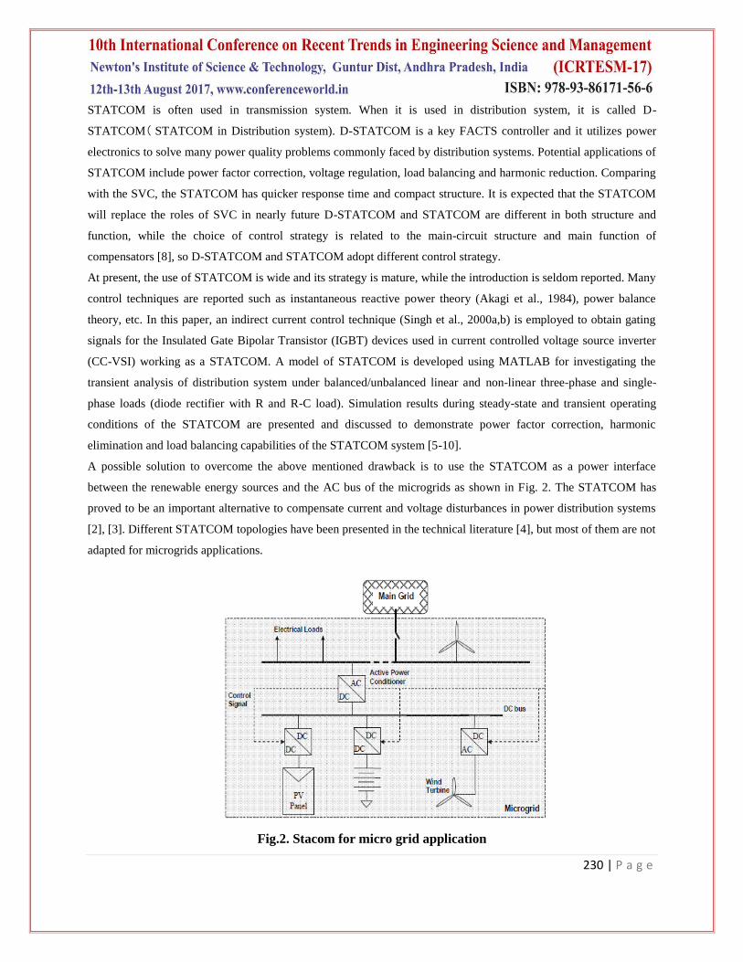
A possible solution to overcome the above mentioned drawback is to use the STATCOM as a power interface
between the renewable energy sources and the AC bus of the microgrids as shown in Fig. 2. The STATCOM has
proved to be an important alternative to compensate current and voltage disturbances in power distribution systems
[2], [3]. Different STATCOM topologies have been presented in the technical literature [4], but most of them are not
adapted for microgrids applications.
Fig.2. Stacom for micro grid application
231 | P a g e
II. STATIC COMPENSATOR (DSTATCOM)
A. Principle of STATCOM
Generally, four-wire APCs have been conceived using fourleg converters [5]. This topology has proved better
controllability [6] than the classical three-leg four-wire converter but the latter is preferred because of its lower
number of power semiconductor devices. In this paper, it is shown that using an adequate control strategy, even with
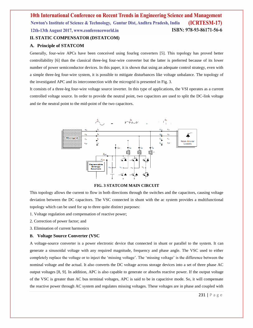
a simple three-leg four-wire system, it is possible to mitigate disturbances like voltage unbalance. The topology of
the investigated APC and its interconnection with the microgrid is presented in Fig. 3.
It consists of a three-leg four-wire voltage source inverter. In this type of applications, the VSI operates as a current
controlled voltage source. In order to provide the neutral point, two capacitors are used to split the DC-link voltage
and tie the neutral point to the mid-point of the two capacitors.
FIG. 3 STATCOM MAIN CIRCUIT
This topology allows the current to flow in both directions through the switches and the capacitors, causing voltage
deviation between the DC capacitors. The VSC connected in shunt with the ac system provides a multifunctional
topology which can be used for up to three quite distinct purposes:
1. Voltage regulation and compensation of reactive power;
2. Correction of power factor; and
3. Elimination of current harmonics
B. Voltage Source Converter (VSC
A voltage-source converter is a power electronic device that connected in shunt or parallel to the system. It can
generate a sinusoidal voltage with any required magnitude, frequency and phase angle. The VSC used to either
completely replace the voltage or to inject the „missing voltage‟. The „missing voltage‟ is the difference between the
nominal voltage and the actual. It also converts the DC voltage across storage devices into a set of three phase AC
output voltages [8, 9]. In addition, APC is also capable to generate or absorbs reactive power. If the output voltage
of the VSC is greater than AC bus terminal voltages, APC is said to be in capacitive mode. So, it will compensate
the reactive power through AC system and regulates missing voltages. These voltages are in phase and coupled with
232 | P a g e
the AC system through the reactance of coupling transformers. Suitable adjustment of the phase and magnitude of
the APC output voltages allows effectives control of active and reactive power exchanges between APC and AC
system. In addition, the converter is normally based on some kind of energy storage, which will supply the converter
with a DC voltage [10].
C. Controller for STATCOM
The three-phase reference source currents are computed using three-phase AC voltages (vta, vtb and vtc) and DC bus
voltage (Vdc) of STATCOM. These reference supply currents consist of two components, one in-phase (Ispdr) and
another in quadrature (Ispqr) with the supply voltages. The control scheme is represented in Fig. 4. The basic
equations of control algorithm of STATCOM are as follows.
D. Computation of In-Phase Components of Reference Supply Current
The instantaneous values of in-phase component of reference supply currents (Ispdr) is computed using one PI
controller over the average value of DC bus voltage of the DSTATCOM (vdc) and reference DC voltage (vdcr) as
where Vde(n) Vdcc-Vdcn) denotes the error in Vdcc and average value of Vdc Kpd and Kid are proportional and
integral gains of the DC bus voltage PI controller. The output of this PI controller (Ispdr) is taken as amplitude of in-
phase component of the reference supply currents. Three-phase in-phase components of the reference supply
currents (isadr, isbdr and iscdr) are computed using the in-phase unit current vectors (ua, ub and uc) derived from
the AC terminal voltages (vtan, vtbn and vtcn), respectively.
where Vtm is amplitude of the supply voltage and it is computed as
The instantaneous values of in-phase component of reference supply currents (isadr, isbdr and iscdr) are computed
as
E. Computation of quadrature components of reference supply current
The amplitude of quadrature component of reference supply currents is computed using a second PI controller over
the amplitude of supply voltage (vtm) and its reference value (vtmr)
Where Vac = Vtmc Vmc(n) denotes the error in Vtmc and computed value Vtmn from Equation (3) and Kpq and
Kiq are the proportional and integral gains of the second PI controller.
233 | P a g e
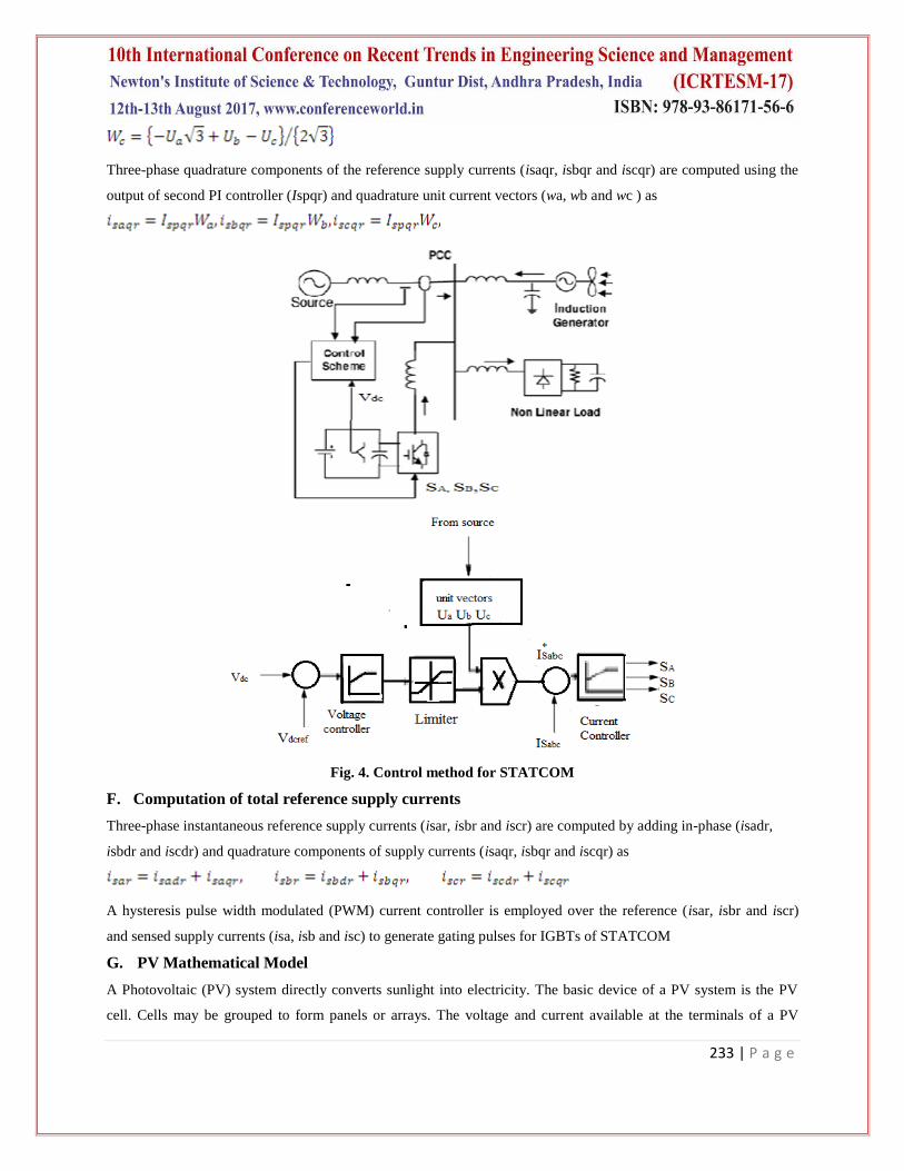
Three-phase quadrature components of the reference supply currents (isaqr, isbqr and iscqr) are computed using the
output of second PI controller (Ispqr) and quadrature unit current vectors (wa, wb and wc ) as
Fig. 4. Control method for STATCOM
F. Computation of total reference supply currents
Three-phase instantaneous reference supply currents (isar, isbr and iscr) are computed by adding in-phase (isadr,
isbdr and iscdr) and quadrature components of supply currents (isaqr, isbqr and iscqr) as
A hysteresis pulse width modulated (PWM) current controller is employed over the reference (isar, isbr and iscr)
and sensed supply currents (isa, isb and isc) to generate gating pulses for IGBTs of STATCOM
G. PV Mathematical Model
A Photovoltaic (PV) system directly converts sunlight into electricity. The basic device of a PV system is the PV
cell. Cells may be grouped to form panels or arrays. The voltage and current available at the terminals of a PV
234 | P a g e
device may directly feed small loads such as lighting systems and DC motors. [7] A photovoltaic cell is basically a
semiconductor diode whose p–n junction is exposed to light. Photovoltaic cells are made of several types of
semiconductors using different manufacturing processes. The incidence of light on the cell generates charge carriers
that originate an electric current if the cell is short circuited.
Fig. 5 Equivalent Circuit of a PV Device including theResistances
The equivalent circuit of PV cell is shown in above diagram the PV cell is represented by a parallel with diode. Rs
and Rp represent se resistance respectively. The output current and cell are represented by I and V.
The net cell current I is composed of the light- generated current Ipv and the diode current Id
(1)
Where
A. Id =Io expqV⁄akT
B. Io = leakage current of the diode
C. q= electron charge
D. k = Boltzmann constant
E. T= temperature of pn junction
F. a= diode ideality constant
The basic equation (1) of the pv cell does not represent the I-V characteristic of a practical PV array. Practical arrays
are composed of several connected PV cells and the observation of the characteristic at the terminals of the PV array
requires the inclusion of additional parameters to the basic equation.
(2)
Where
Is the thermal voltage of the array with Ns cells connected in series. Cells connected in series provide greater output
voltages. The I-V characteristic of a practical PV cell with maximum power point (MPP), Short circuit current (Isc)
and Open circuit voltage (Voc) is shown in fig. 6. The MPP represents the point at which maximum power is
obtained.
235 | P a g e
Vmp and Imp are voltage and current at MPP respectively. The output from PV cell is not the same throughout the
day; it varies with varying temperature and insolation (amount of radiation). Hence with varying temperature and
insolation maximum power should be tracked so as to achieve the efficient operation of PV system.
III. MATAB/SIMULINK MODELING OF STATCOM
3.1 Modeling of Power Circuit
Fig.7. Matlab/Simulink Model of STATCOM Power Circuit with RES
Fig. 7. Shows the complete MATLAB model of STATCOM along with control circuit and Distributed generation
system. The power circuit as well as control system are modelled using Power System Blockset and Simulink. The
grid source is represented by three-phase AC source. Three-phase AC loads are connected at the load end.
STATCOM is connected in shunt and it consists of PWM voltage source inverter circuit and a DC capacitor
connected at its DC bus. An IGBT-based PWM inverter is implemented using Universal bridge block from Power
Electronics subset of PSB. Snubber circuits are connected in parallel with each IGBT for protection. Simulation of
STATCOM system is carried out for linear and non-linear loads. The non-linear load on the system is modelled
using R and R-C circuits connected at output of the diode rectifier. Provision is made to connect loads in parallel so
236 | P a g e
that the effect of sudden load addition and removal is studied. The feeder connected from the three-phase source to
load is modelled using appropriate values of resistive and inductive components.
3.1 Modeling of Control Circuit
Fig. 8 shows the control algorithm of STATCOM with two PI controllers. One PI controller regulates the DC link
voltage while the second PI controller regulates the terminal voltage at PCC. The in-phase components of
STATCOM reference currents are responsible for power factor correction of load and the quadrature components of
supply reference currents are to regulate the AC system voltage at PCC.
Fig. 8. Control Circuit
The output of PI controller over the DC bus voltage (Ispdr) is considered as the amplitude of the in-phase
component of supply reference currents and the output of PI controller over AC terminal voltage (Ispqr) is
considered as the amplitude of the quadrature component of supply reference currents. The instantaneous reference
currents (isar, isbr and iscr) are obtained by adding the in-phase supply reference currents (isadr, isbdr and iscdr) and
quadrature supply reference currents (isaqr, isbqr and iscqr). Once the reference supply currents are generated, a
carrierless hysteresis PWM controller is employed over the sensed supply currents (isa, isb and isc) and
instantaneous reference currents (isar, isbr and iscr) to generate gating pulses to the IGBTs of STATCOM. The
controller controls the STATCOM currents to maintain supply currents in a band around the desired reference
current values. The hysteresis controller generates appropriate switching pulses sixIGBTs of the VSI working as
STATCOM.
IV . SIMULATION RESULTS
Here Simulation results are presented for two cases. In case one load is balanced non linear with Battery Energy
Storage System (BESS) case two load is balanced non linear with PV energy system for regulating the voltage.
237 | P a g e
Case 1: Balanced non linear with Battery Energy Storage System (BESS):
Performance of STATCOM connected to a weak supply system for power factor correction and load balancing. The
variation of performance variables such as supply voltages (vsa, vsb and vsc), terminal voltages at PCC (vta, vtb
and vtc), supply currents (isa, isb and isc), load currents (ila, ilb and ilc), STATCOM currents (ica, icb and icc) and
DC link voltage (Vdc) are shown below.
Fig.9. Simulation results for Balanced Non Linear Load with BESS ( a) Source current. (b) Load current. (c)
Inverter injected current. (d) grid voltage.
Fig. 9 shows the source current, load current and compensator current and grid voltage plots respectively. Here
compensator is turned on at 0.1 seconds.
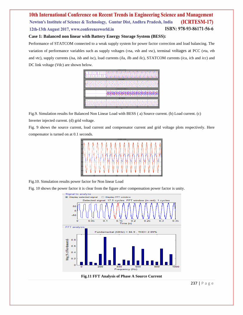
Fig.10. Simulation results power factor for Non linear Load
Fig. 10 shows the power factor it is clear from the figure after compensation power factor is unity.
Fig.11 FFT Analysis of Phase A Source Current
238 | P a g e
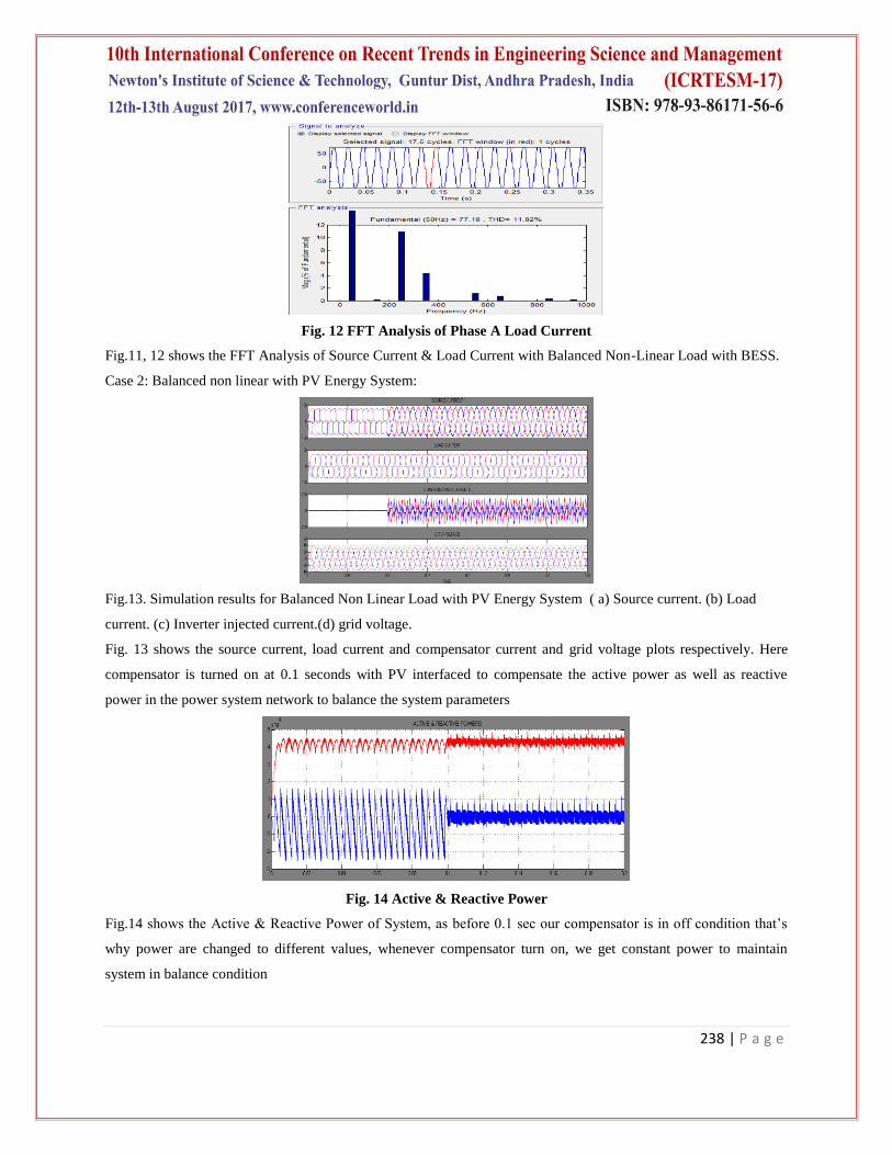
Fig. 12 FFT Analysis of Phase A Load Current
Fig.11, 12 shows the FFT Analysis of Source Current & Load Current with Balanced Non-Linear Load with BESS.
Case 2: Balanced non linear with PV Energy System:
Fig.13. Simulation results for Balanced Non Linear Load with PV Energy System ( a) Source current. (b) Load